1
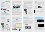
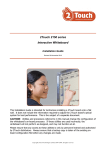
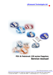
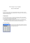
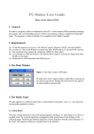
E-Series
Quick Start Guide
ER450 Data Radio
Related Products and Documentation
2.0 Mounting and Environmental Considerations
•
Base Station EB450
•
Hot Standby Base Station EH450
•
Duplexers
•
TVIEW+ Management Suite
•
E Series User Manual
The ER450 radio comes complete with a mounting
cradle and is attached to a panel or tray by means of
screws or bolts, using the hole slots provided.
Note: In high power or high temperature applications,
it is desirable to mount the radio with the heatsink
uppermost to allow ventalation for the heatsink.
The radio should be mounted in a clean and dry
location, protected from water, excessive dust,
corrosive fumes, extremes of temperature and direct
sunlight. Please allow sufficient passive or active
ventilation to allow the radio modem’s heatsink to
operate efficiently.
Step-by-Step Point to Point Setup
1.0 Introduction
Welcome to the Quick Start Guide for the ER450 Data
Radio. This guide provides step-by-step instructions, with
simple explanations to get you up-and-running. For further
information, please refer to the E Series User Manual.
2.1 Typical Radio Setup
Contents
1.0
Introduction.............................................................................1
2.0
Mounting and Environmental Considerations.....3
3.0
Connecting Antennas and RF Feeders....................4
4.0
Communications Ports.....................................................5
5.0
Power Supply and Protection........................................9
6.0
TVIEW+ Management Suite...........................................11
7.0
Optimising the Antenna for VSWR............................13
8.0
LED Indicators and Test Outputs..............................13
9.0
Verifying Operational Health.........................................14
10.0
Support Options...................................................................16
2.2 ER450 Connections Layout
Lightning
Arrestor
E-Series Remote
Omni-Directional
or Direction Yagi
Antenna
3.0 Connecting Antennas and RF Feeders
Mains Supply
RS232 Serial
Device (RTU/PLC)
Connected to port
A and/or port B
Laptop/PC running TView+
Diagnostics Connected to
System Port
1
2
System
Port
Pin 1
Pin 2
Pin 3
Pin 4
Pin 5
Pin 6
Pin 7
Pin 8
Description
System port data out (RS232)
System port data in (RS232)
Factory Use Only - Do not connect
Shutdown
Programming Use Only (Grounded)
Factory Use Only - Do not connect
Ground
External PTT
DB9 Female
Pin 2
Pin 3
No Connection
No Connection
Pin 5
No Connection
Pin 5
No Connection
Fig 4
Regulated Power Supply
(110/220VAC to 13.8
VDC Nominal)
Fig 3
3
The RF antenna system should be installed in
accordance with the manufacturers notes.
The RF connector used on the ER450 radio is an N
Type female connector. Always use good quality low
loss feeder cable, selected according to the length
of the cable run. Ensure all external connections are
waterproofed using amalgamating tape.
Preset directional antennas in the required direction
using a compass, GPS, or visual alignment and ensure
correct polarisation (vertical or horizontal).
4.2 User Interfaces - Ports A & B
10.0 Support Options
Each user port (A & B) is wired as a RS232 DCE,
configurable for no handshaking (3-wire) interface, or for
hardware or software (X-on/X-off) flow control. In most
systems flow control is not required, in which case only 3
wires need to be connected between the radio and the
application device.
E-mail Technical Support
4
When e-mailing questions to our support staff, make sure
you tell us the exact model number (and serial number
if possible) of the Schneider Electric equipment you are
working with. Include as much detail as possible about the
situation, and any tests that you have done which may
help us to better understand the issue. If possible, please
include your telephone contact information should we
wish to further clarify any issues.
4.3 Typical pins used:
• Pin 2 (RxD) - data output from the radio modem,
• Pin 3 (TxD) - data input to the radio modem,
• Pin 5 (SG) - signal ground.
Fig 6
Fig 5
Contact Details
4.0 Communications Ports
Refer to User Manual for further details of other cable configurations.
Technical Support: The Americas
Available: Monday to Friday 8:00am - 6:30pm
Eastern Standard Time
Toll free within North America: 1-888-226-6876
Direct Worldwide: +1 (613) 591-1943
Email: [email protected]
4.1 System Port - RJ45
The System Port is a multi-function interface used for:
• Programming / Configuration of the radio
• Remote Diagnostics connections
Technical Support: Asia Pacific
To access these functions use the standard ER450
System Cable assembly (RJ45 Cable and RJ45 to DB9
Adaptor).
Special user pinouts:
Available: Monday to Friday 8:30am - 5:30pm
Australian Eastern Standard Time
Direct Worldwide: +61 3 8773 0100
Email: [email protected]
Technical Support: Europe, Africa,
Middle East
• Shutdown (Pin 4) - Active low for power save function
•
External PTT (Pin 8) - Provides a manual PTT override
facility for enabling the transmitter. For testing this can be
activated by connecting PTT (Pin 8 ) to Gnd (Pin 7).
Available: Monday to Friday 8:30am - 5:30pm
Central Europe Standard Time
Direct Worldwide: +31 (71) 579 1655
Email: [email protected]
Fig 7
Fig 8
5
6
7
Issue : 06-11
Printed in Australia
16
6.0 TVIEW+ Management Suite - Radio Configuration
4.4 Activating the Transmitter
In most systems, the transmitter by default is controlled
automatically by the radio when it has data to transmit.In
some systems, such as full duplex point-to-point links or full
duplex point-to-multipoint base stations, it is desirable to run
the transmitter all the time (hot keyed).Two mechanisms are
provided to do this:
This TVIEW+ Management Suite allows a number of features
including: Configuration (Local - serial, or Remote - over-the-air),
Remote DiagnosticsFacilities and Firmware Upgrades.
• Refer to section 4.1 for detail on how to activate the
units transmitter via the system port.
The configuration wizard can be used to provide Quick Start
generic templates for the types of systems architecture you wish
to employ.
• The radio modem can be configured to transmit
continuously whenever powered To operate in
this mode, the radio must be configured via the
programming software. or.
CAUTION
Example: Local configuration session 1 Attach the programming cable from the PC to the System Port of the radio (see fig 6 & 7 )
When the radio is configured to transmit continuously,
ensure an RF load is present BEFORE applying power
to the unit.
RS232 Connector Pin outs (DCE)
Port A and B, Female DB9
2 Launch TVIEW & Select “Programmer”
3 Select “Read” the radio
5.0 Power Supply and Protection (fusing)
5 Select “Write” the parameters back to the radio
The ER450 radio modem is designed and calibrated to
operate from a 13.8Vdc regulated supply, but will operate
from 10-16 volts (filtered) DC.
The current requirement is typically 120mA in receive
mode, and will vary in transmit mode according to RF output
power level (typically 0.5-1.5 amps).
CAUTION
There is NO readily serviceable internal fuse, and therefore
the radio modem MUST be externally fused with a fuse and
fuse holder (ER450: 3 amp fast-blow fuse).
8
Fig 9
7.0 Optimising the Antenna for VSWR and best RX
signal
Once the unit is operational, it is important to optimise the
antenna tuning.
9
This can be done by using the (0-5Vdc) output on Pin 9 (see fig
11) of Port B to indicate signal strength (RSSI). This voltage can
be converted to dBm using the chart below.
8.1 Radio is Powered
The “RX/SYNC” LED is used to indicate the state of the receiver. If the LED is off, no signal is being received.
A RED indication shows that an RF carrier is being received, but no
data stream can be decoded. This may indicate the presence of
interference, another user on the channel or incorrect configuration.
Successful power-up is indicated by the “PWR” LED indicating
a continuous (healthy) GREEN state. Note that this LED is
turned RED when the transmitter is active.
A continuous GREEN indication shows that the modem is locked
and synchronised to the incoming signal, and has excellent Bit
Error Rate (BER). Any losses of synchronisation (BER errors) are
shown as a visible RED flicker of the LED.
Note: This may only be apparent on a PTMP slave when receiving.
Internal radio management software monitors many aspects
of the radio hardware. Under certain circumstances radio
faults may prevent normal operation. In the event that these
fault conditions occur, the radio will enter an ERROR state and
this will be indicated by flashing ALL LEDs RED, then flashing a
pattern of GREEN LEDs. The pattern of GREEN LEDs represent
a specific type of error that has occured. See Table below.
Analog RSSI Output Characteristics - E Series Data Radio
Port A Port B Synch/ Pwr/TX Error Diagnosis
RXSig
5
4.5
RSSI (DC Volts)
4
3.5
OFF
OFF
OFF
ON
External Supply Voltage
out of spec.
ON
ON
OFF
OFF
ON
OFF
OFF
ON
RX VCO Out of Lock.
TX VCO Out of Lock.
3
2.5
2
ER Fatal Error
ER Receviing and decoding
ER Receviing un-decodable packets
9.0 Verifying Operational Health
It is possible to verify the operation of the radio modem using the
indicators provided by the unit. The state of the transmitter and receiver,
and data flow can be interpreted by the indicator LEDs (see below).
Note: Port A & B’s RxD & TxD will be Active on Data Flow
Full Duplex - PTP Master or Slave
Full Duplex - PTMP Master Tx
1
0
-120
8.4 Data Flow “breakout” LEDs
-110
-100
-90
-80
-70
-60
-50
VSWR testing is achieved by activating the radio’s transmitter
using:
Input data to be transmitted is shown as a RED flash, and received
data to be output to the port is shown as a GREEN flash.
a) An RTS loop as described in Section 4.4, or
Refer to the User Manual for further details of VSWR testing.
Half Duplex - Master or Slave (Tx)
There are also two LEDs to indicate data flow into and out of the
two user ports.
-40
RF Level (dBm)
b) A system port PTT plug as described in Section 4.1
Half Duplex - PTMP Slave Rx
12
If data is alternately flowing in and out quickly, then the indicator
appears orange.
13
11
Important Notices for Class 1,
Division 2, Groups A,B,C&D
Hazardous Locations
Important Notices for Class I, Division 2, Groups A, B, C & D
Hazardous Locations
Applies to models ER450-xxxxx-xHx(CSA Marked)
This product is available for use in Class I, Division 2, Groups A, B, C & D
Hazardous Locations. Such locations are defined in Article 500 of the US
National Fire Protection Association (NFPA) publication NFPA 70, otherwise
known as the National Electrical Code and in Section 18 of the Canadian
Standards Association C22.1 (Canadian Electrical Code).
The transceiver has been recognised for use in these hazardous locations by
the Canadian Standards Association (CSA) International. CSA certification is
in accordance with CSA Standard C22.2 No. 213-M1987 and UL Standard
1604 subject to the following conditions of approval:
1. The radio modem must be mounted in a suitable enclosure so that a
tool is required to gain access for disconnection of antenna, power and
communication cables.
2. The antenna, DC power and interface cables must be routed through
conduit in accordance with the National Electrical Codes.
3. Installation, operation and maintenance of the radio modem should be in
accordance with the radio modem’s user manual and the National Electrical Codes.
4. Tampering or replacement with non-factory components may adversely
affect the safe use of the radio modem in hazardous locations and may void
the approval.
1.5
0.5
Refer to User Manual for detailed operation of advanced features.
10
8.5 Received Signal Indicator
8.2 Radio Errors
Fig 11
The radio is designed to self protect from permanent
damage if the voltage exceeds 16Vdc or if reverse polarity
is applied. The radio may need to be returned for service if
this occurs.
The radio modem can also be damaged if there is any
potential difference between the chassis-ground, RS232
signal ground, power (-) input, or antenna coaxial shield.
Before connecting any wiring, ensure all components are
earthed to a common ground point (please pay particular
attention to 24V PLC power systems where converters are
used).
Connect the antenna and RS 232 plugs BEFORE applying
power to the unit. Lastly, before inserting the power plug,
please re-check that the polarity and voltage on the DC
power plug is correct using a multimeter.
8.0 LED Indicators & Test outputs
If all the LEDs are off, no power is reaching the radio modem.
In the case of a directional antenna, it will be necessary to align
the antenna for the best received signal.
4 Change the configuration as required
Fig 10
5. A power connector retainer with thumbwheel screw as supplied by Trio
Datacom MUST be used.
WARNING EXPLOSION HAZARD
Half Duplex - Master or Slave (Rx)
14
Do not disconnect equipment unless power has been switched off or the
area is known to be non-hazardous. Substitution of components may impair
suitability for Class I, Division 2. Refer to Articles 500 through 502 of the
National Electrical Code (NFPA 70) and Section 18 of CSA C22.1 for further
information on hazardous locations and approved Division 2 wiring methods.
15