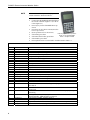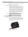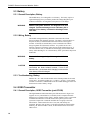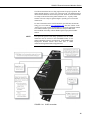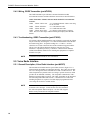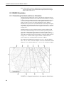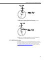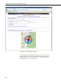
1
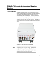
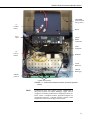
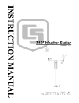
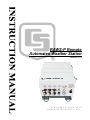
RAWS-P Remote
Automated Weather Station
Revision: 4/12
C o p y r i g h t © 2 0 0 6 - 2 0 1 2
C a m p b e l l S c i e n t i f i c , I n c .
Warranty
“PRODUCTS MANUFACTURED BY CAMPBELL SCIENTIFIC, INC. are
warranted by Campbell Scientific, Inc. (“Campbell”) to be free from defects in
materials and workmanship under normal use and service for twelve (12)
months from date of shipment unless otherwise specified in the corresponding
Campbell pricelist or product manual. Products not manufactured, but that are
re-sold by Campbell, are warranted only to the limits extended by the original
manufacturer. Batteries, fine-wire thermocouples, desiccant, and other
consumables have no warranty. Campbell's obligation under this warranty is
limited to repairing or replacing (at Campbell's option) defective products,
which shall be the sole and exclusive remedy under this warranty. The
customer shall assume all costs of removing, reinstalling, and shipping
defective products to Campbell. Campbell will return such products by surface
carrier prepaid within the continental United States of America. To all other
locations, Campbell will return such products best way CIP (Port of Entry)
INCOTERM® 2010, prepaid. This warranty shall not apply to any products
which have been subjected to modification, misuse, neglect, improper service,
accidents of nature, or shipping damage. This warranty is in lieu of all other
warranties, expressed or implied. The warranty for installation services
performed by Campbell such as programming to customer specifications,
electrical connections to products manufactured by Campbell, and product
specific training, is part of Campbell’s product warranty. CAMPBELL
EXPRESSLY DISCLAIMS AND EXCLUDES ANY IMPLIED
WARRANTIES OF MERCHANTABILITY OR FITNESS FOR A
PARTICULAR PURPOSE. Campbell is not liable for any special, indirect,
incidental, and/or consequential damages.”
Assistance
Products may not be returned without prior authorization. The following
contact information is for US and international customers residing in countries
served by Campbell Scientific, Inc. directly. Affiliate companies handle
repairs for customers within their territories. Please visit
www.campbellsci.com to determine which Campbell Scientific company serves
your country.
To obtain a Returned Materials Authorization (RMA), contact CAMPBELL
SCIENTIFIC, INC., phone (435) 227-9000. After an applications engineer
determines the nature of the problem, an RMA number will be issued. Please
write this number clearly on the outside of the shipping container. Campbell
Scientific's shipping address is:
CAMPBELL SCIENTIFIC, INC.
RMA#_____
815 West 1800 North
Logan, Utah 84321-1784
For all returns, the customer must fill out a "Statement of Product Cleanliness
and Decontamination" form and comply with the requirements specified in it.
The form is available from our web site at www.campbellsci.com/repair. A
completed form must be either emailed to [email protected] or faxed to
(435) 227-9106. Campbell Scientific is unable to process any returns until we
receive this form. If the form is not received within three days of product
receipt or is incomplete, the product will be returned to the customer at the
customer's expense. Campbell Scientific reserves the right to refuse service on
products that were exposed to contaminants that may cause health or safety
concerns for our employees.
RAWS-P Table of Contents
PDF viewers: These page numbers refer to the printed version of this document. Use the
PDF reader bookmarks tab for links to specific sections.
1. Introduction..................................................................1
2. Getting Started.............................................................2
3. Station Siting and Orientation ....................................5
3.1
3.2
3.3
3.4
3.5
3.6
3.7
General Description ..................................................................................5
Air Temperature and Relative Humidity ..................................................5
Precipitation..............................................................................................5
Solar Radiation .........................................................................................5
Wind Speed and Direction........................................................................5
Barometric Pressure..................................................................................6
Fuel Moisture and Fuel Temperature........................................................6
4. Sensor Wiring and Troubleshooting..........................6
4.1 Air Temperature and Relative Humidity ..................................................6
4.1.1 General Description, Air Temperature and Relative Humidity
(part #HC2S3-LQ) .................................................................................6
4.1.2 Wiring, Air Temperature and Relative Humidity (part
#HC2S3-LQ)..........................................................................................6
4.1.3 Troubleshooting, Air Temperature and Relative Humidity (part
#HC2S3-LQ)..........................................................................................6
4.2 Rain Gage .................................................................................................7
4.2.1 General Description, Rain Gage (part #TE525-LQ) .......................7
4.2.2 Wiring, Rain Gage (part #TE525-LQ)............................................7
4.2.3 Troubleshooting, Rain Gage (part #TE525-LQ).............................7
4.3 Solar Radiation .........................................................................................7
4.3.1 General Description, Pyranometer (part #CS300-LQ)....................7
4.3.2 Wiring, Pyranometer (part #CS300-LQ) ........................................7
4.3.3 Troubleshooting, Pyranometer (part #CS300-LQ) .........................8
4.4 Wind Speed and Direction........................................................................8
4.4.1 Windset (part #034B-LQ) ..............................................................8
4.4.1.1 General Description, Windset (part #034B-LQ) ...................8
4.4.1.2 Wiring, Windset (part #034B-LQ) ........................................8
4.4.1.3 Troubleshooting, Windset (part #034B-LQ) .........................8
4.4.2 2-D WindSonic ...............................................................................9
4.4.2.1 General Description, 2-D WindSonic (part
#WindSonic-LQ) ............................................................................9
4.4.2.2 Wiring, 2-D WindSonic (part #WindSonic-LQ)...................9
4.4.2.3 Troubleshooting, 2-D WindSonic (part #WindSonic-LQ)....9
4.5 Barometric Pressure..................................................................................9
4.5.1 General Description, Barometric Pressure (part #CS100-QD) .......9
4.5.2 Wiring, Barometric Pressure (part #CS100) ...................................9
4.5.3 Troubleshooting, Barometric Pressure (part #CS100) ..................10
i
RAWS-P Table of Contents
4.6 Fuel Moisture and Fuel Temperature..................................................... 10
4.6.1 General Description, Fuel Moisture/Fuel Temperature (part
#CS516-LQ)........................................................................................ 10
4.6.2 Wiring, Fuel Moisture/Fuel Temperature (part #CS516-LQ) ...... 10
4.6.3 Troubleshooting, Fuel Moisture/Fuel Temperature (part
#CS516-LQ)........................................................................................ 11
5. Equipment Wiring and Troubleshooting..................11
5.1 Solar Panels............................................................................................ 11
5.1.1 General Description, Solar Panel (part #SP10/20-LQ) ................ 11
5.1.2 Wiring, Solar Panel (part #SP10/20-LQ) ..................................... 11
5.1.3 Troubleshooting, Solar Panel (part #SP10/20-LQ) ...................... 12
5.2 Charger/Regulator.................................................................................. 12
5.2.1 General Description, 12 V Charger/Regulator (part #CH100)..... 12
5.2.2 Wiring, 12 V Charger/Regulator (part #CH100) ......................... 13
5.2.3 Troubleshooting, 12 V Charger/Regulator (part #CH100) .......... 13
5.3 Battery.................................................................................................... 14
5.3.1 General Description, Battery........................................................ 14
5.3.2 Wiring, Battery............................................................................. 14
5.3.3 Troubleshooting, Battery.............................................................. 14
5.4 GOES Transmitter ................................................................................. 14
5.4.1 General Description, GOES Transmitter (part #TX320) ............. 14
5.4.2 Wiring, GOES Transmitter (part #TX320) .................................. 16
5.4.3 Troubleshooting, GOES Transmitter (part #TX320) ................... 16
5.5 Voice Radio Interface ............................................................................ 16
5.5.1 General Description, Voice Radio Interface (part #VSP3) .......... 16
5.5.2 Wiring, Voice Radio Interface (part #VSP3) ............................... 17
5.5.3 Troubleshooting, Voice Radio Interface (part #VSP3) ................ 17
5.6 CR1000 Keyboard/Display .................................................................... 18
5.6.1 General Description, CR1000 Keyboard/Display (part
#CR1000KD) ...................................................................................... 18
5.6.2 Wiring, CR1000 Keyboard/Display (part #CR1000KD) ............. 18
5.6.3 Troubleshooting, CR1000 Keyboard/Display (part
#CR1000KD) ...................................................................................... 18
5.7 CR1000 Datalogger (part #CR1000) ..................................................... 19
5.7.1 General Description, CR1000 Datalogger (part #CR1000) ......... 19
5.7.2 Wiring, CR1000 Datalogger (part #CR1000) .............................. 20
5.7.3 Troubleshooting, CR1000 Datalogger (part #CR1000) ............... 20
6. Desiccant ....................................................................20
6.1 When to Replace Desiccant ................................................................... 20
6.2 Reusing Desiccant.................................................................................. 20
7. Sensor and Equipment Maintenance .......................21
7.1 Sensor and Equipment Maintenance...................................................... 21
8. References..................................................................21
8.1 Specifications, Equipment and Sensor................................................... 21
8.2 Siting References ................................................................................... 21
ii
RAWS-P Table of Contents
8.3 RAWS Orientation .................................................................................22
8.3.1 Determining True North and Sensor Orientation..........................22
8.3.2 USGS Web Calculator ..................................................................23
Figures
1-1. Color coded, keyed connector panel .......................................................1
2-1. Inside environmental enclosure (optional equipment shown) .................3
5.2-1. 12 volt charger/regulator ....................................................................12
5.4-1. GOES transmitter ...............................................................................15
5.5-1. Voice radio interface ..........................................................................17
5.6-1. CR1000 Keyboard/Display ................................................................18
5.7-1. CR1000 and printed circuit wiring panel ...........................................19
5.7-2. Printed circuit board wiring panel connector ID ................................19
8.3-1. Magnetic declination for the contiguous United States......................22
8.3-2. A declination angle East of True North (positive) is subtracted
from 360 (0) degrees to find True North...................................................23
8.3-3. A declination angle West of True North (negative) is subtracted
from 0 (360) degrees to find True North...................................................23
8.3-4. USGS Web Calculator .......................................................................24
Table
2-1. Public Variables ......................................................................................4
iii
RAWS-P Table of Contents
iv
RAWS-P Remote Automated Weather
Station
1. Introduction
The RAWS environmental enclosure can be used for configuring a custom
Remote Automated Weather Station (RAWS) that matches the requirements of
your application. The aluminum environmental enclosure houses a 12 V
rechargeable battery and a CR1000 datalogger. The outside of the enclosure
has color-coded, keyed connectors (Figure 1-1) for attaching the sensors.
Besides the connectors, a wiring panel is included that allows the measurement
of additional sensors. Communication options include satellite transmitter and
voice radio interface module. Additional communication equipment
(telephone, cellular phone, radio) can be added to the station. The RAWS data
collection platform is ideal for configuring a custom remote automated weather
station.
FIGURE 1-1. Color coded, keyed connector panel
NOTE
The RAWS-P comes with a generic program. Modifications to
this generic program will require datalogger support software
(LoggerNet or PC400) purchased from Campbell Scientific, Inc.
Please contact a Campbell Scientific Application Engineer for
programming assistance. Campbell Scientific company contact
information is listed on the last page of this manual.
1
RAWS-P Remote Automated Weather Station
2. Getting Started
2
NOTE
Set up and test your station before field deployment.
NOTE
Keep this manual and the CR1000KD Keyboard Display
with the RAWS. Review the station siting and orientation
section before field deployment. If a problem is encountered,
review the equipment wiring and troubleshooting sections in this
manual.
NOTE
After siting and leveling the RAWS station, open the enclosure and
(1) connect the battery cable and (2) verify the CH100 switch is in
the ‘on’ position. When this equipment is not in use (i.e.,
transport or storage), disconnect battery cable to the CH100.
RAWS-P Remote Automated Weather Station
CR1000KD
packed in foam
(may go here)
(1)
Connect
battery
Battery
SC12
Cable
TX320
GOES
Transmitter
VSP3
Vosponder
(2)
Turn on
CH100
RF Radio
CS100
Barometer
CR1000
Datalogger
CR1000
power in
CR1000 Wiring Panel
FIGURE 2-1. Inside environmental enclosure (optional equipment
shown)
NOTE
The RAWS-P comes with a generic program. Modifications to
this generic program will require datalogger support software
(LoggerNet or PC400) purchased from Campbell Scientific, Inc.
Please contact a Campbell Scientific Application Engineer for
programming assistance. Campbell Scientific company contact
information is listed on the last page of this manual.
3
RAWS-P Remote Automated Weather Station
NOTE
Use the CR1000KD Keyboard Display to see the
“Public Variables” shown in Table 2-1.
•
•
•
•
•
•
•
•
Connect the CR1000KD Keyboard Display to
the CS I/O connector (Figure 5.7-2) or SC12
Cable (Figure 2-1)
Press any key for the CR1000KD Power up
Screen
Press Enter to move down a menu (Press Esc
to move up a menu)
(Press up/down arrow to select item)
Press any key for Power up Screen
Select Data, press Enter
Press ^ to turn on/off backlight
Select Real Time Tables, press Enter
Press <> to adjust contrast
Select Public, press Enter
Press up/down arrow to see the Public Variables listed in Table 2-1
TABLE 2-1. Public Variables
Number
18
Name
Sensor Variables
Batt_Volt
AirTempF
RH
TdewF
SlrW
Rain_in
RainTot
WS_mph
WindDir
WSDiag
MaxWS
MaxWD
SlrMJ
BP_inHg
BPelev_ft
FuelT_F
FuelM
GOES Variables
CountDwn
19
Clockgood
20
TimeToXmit
21
SWR
22
23
24
25
FwdPower
RefPower
RC_Data
Setup_RC
1
2
3
4
5
6
7
8
9
10
11
12
13
14
15
16
17
4
Function
System power supply voltage
HC2S3 Air Temperature in Degrees F
HC2S3 Relative Humidity in Percent
Dew point in Deg F, calculated from HC2S3 data
Solar Radiation in Watts, pyranometer
Temporary rain, cleared every scan
TE525 Cumulative rain fall in inches
Wind Speed in MPH
Wind Direction
Only for Wind Sonic data, zero otherwise
MaxWS, reset 2 minutes before transmit
Direction of wind during Max wind speed
Solar Radiation in MJoules
Hourly - Barometric pressure, inHg
Elevation, to correct Barometric pressure
Hourly - Fuel temperature in degrees F
Hourly - Fuel Moisture, % moisture by weight
True or False: True indicates GPS fix good and program is collection data. False
until GPS fix
True or False: True after GPS fix and CR1000 clock has been set to match
TX320 clock
Seconds until transmit time. Indicates CR1000 and TX320 are properly setup
and running
Standing Wave Ratio (SWR), only after a transmission. Indicates condition of
antenna and cable. SWR should be less than 2.0
Forward Power in dBm, should be about 37
Reflected power in dBm, should be about 25 or less
Only valid after first transmission. Anything other than zero is a problem
Indicates if CR1000 could setup TX320. Zero is success or has not run
RAWS-P Remote Automated Weather Station
3. Station Siting and Orientation
3.1 General Description
Selecting an appropriate site for the RAWS is critical in order to obtain
accurate meteorological data. In general, the site should be representative of
the general area of interest and away from the influence of obstructions such as
buildings and trees.
NOTE
WARNING
See Section 8 for siting references.
If any part of the weather station comes in contact with
power lines, you could be killed. Contact local utilities
for the location of buried utility lines before digging or
driving ground rods.
3.2 Air Temperature and Relative Humidity
A temperature and relative humidity sensor should be located over an open
level area at least 9 m in diameter (EPA). The surface should be covered by
short grass, or where grass does not grow, the natural earth surface. The sensor
must be housed inside a radiation shield and adequately ventilated.
Situations to avoid include: 1) large industrial heat sources, 2) rooftops, 3)
steep slopes, 4) sheltered hollow, 5) high vegetation, 6) shaded areas,
7) swamps, 8) areas where snow drifts occur, and 9) low places holding
standing water after rains.
3.3 Precipitation
A rain gauge should be located over an open level area covered by short grass,
or where grass does not grow, the natural earth surface. Level the rain gage.
NOTE
Take off the funnel and remove the rubber band securing the
tipping bucket mechanism during transport.
3.4 Solar Radiation
A solar radiation sensor should be located to avoid shadows on the sensor at
any time. Orient the solar radiation sensor where the solar radiation sensor
faces south (northern hemisphere) minimizing the chance of shading from
other weather station structures. Reflective surfaces and sources of artificial
radiation should be avoided. Level the solar radiation sensor.
3.5 Wind Speed and Direction
A wind sensor should be located over open level terrain and at a distance of at
least ten times (EPA) the height of any nearby building, tree, or other
obstruction.
5
RAWS-P Remote Automated Weather Station
3.6 Barometric Pressure
The barometric pressure sensor is mounted to the back plate inside the RAWS
environmental enclosure.
3.7 Fuel Moisture and Fuel Temperature
The fuel moisture and fuel temperature sensor should be left outside at the field
site continually exposed to the same conditions as forest fuels. The fuel
moisture and fuel temperature dowel rods absorb and desorb moisture from its
surroundings. Install the probes horizontally on the mounting stake and face
the sensors south (northern hemisphere) above a representative forest floor duff
layer. Place the sensor away from foot traffic areas.
4. Sensor Wiring and Troubleshooting
4.1 Air Temperature and Relative Humidity
4.1.1 General Description, Air Temperature and Relative Humidity (part
#HC2S3-L-RQ)
The HC2S3 Rotronic’s HydroClip2 Air Temperature and Relative Humidity
Probe has a -RQ cable termination option that allows it to connect to the
RAWS-P. This probe contains a Platinum Resistance Thermometer (PRT) and
a Rontronic’s IN1 capacitive relative humidity sensor. Voltage is output for
each of the probe’s sensors.
4.1.2 Wiring, Air Temperature and Relative Humidity (part #HC2S3-L-RQ)
The temp/RH sensor is connected to the RAWS connector panel “TEMP/RH”
connector COLOR CODED ORANGE. This sensor is internally wired from
the RAWS connector panel to the CR1000 datalogger.
Connector Panel “TEMP/RH” connector COLOR CODED ORANGE
Connector Pin A Temp Hi
to CR1000 1L
Connector Pin B Sensor excitation
to CR1000 EX1
Connector Pin C Sensor signal Lo/AG to CR1000 AG
Connector Pin D Power ground
to CR1000 Ground
Connector Pin E RH signal
to CR1000 1H
Connector Pin F SW_12V
to CR1000 SW_12V
4.1.3 Troubleshooting, Air Temperature and Relative Humidity (part
#HC2S3-L-RQ)
Check the sensor cable. Disconnect the connector and look for damaged pins.
Verify that the sensor body is connected to the sensor head. Under the filter
assembly, verify the sensors are connected but not touching. Try connecting a
substitute sensor. Obtain a Return Material Authorization (RMA) number
before returning this sensor to Campbell Scientific for repair.
NOTE
6
Consult the HC2S3-L manual for more information.
RAWS-P Remote Automated Weather Station
4.2 Rain Gage
4.2.1 General Description, Rain Gage (part #TE525-LQ)
The Texas Electronics Rain Gage (part #TE525-LQ) is an adaptation of a
Weather Bureau tipping bucket rain gage. The rain gage has a 6 inch collector.
The rain gage sensor output has a switch closure for each bucket tip. Level the
rain gage.
4.2.2 Wiring, Rain Gage (part #TE525-LQ)
The rain gage is connected to the RAWS connector panel “PRECIP” connector
COLOR CODED BLUE. This sensor is internally wired from the RAWS
connector panel to the CR1000 datalogger.
Connector Panel “PRECIP” connector COLOR CODED BLUE
Connector Pin A Tipping Bucket
to CR1000 C6
Connector Pin B 5V
to CR1000 5V
Connector Pin C Ground
to CR1000 Ground
4.2.3 Troubleshooting, Rain Gage (part #TE525-LQ)
Check the sensor cable. Disconnect the connector and use a DVM to check the
resistance between Pin A (sensor signal) and Pin C (sensor ground). The
resistance should read as an open circuit until you move the rain gage tipping
mechanism where the magnet swings past the reed relay. Try connecting a
substitute sensor. Obtain a Return Material Authorization (RMA) number
before returning this sensor to Campbell Scientific for repair.
NOTE
Consult the TE525-L manual for more information.
4.3 Solar Radiation
4.3.1 General Description, Pyranometer (part #CS300-LQ)
The Apogee Pyranometer (part #CS300-LQ) measures incoming solar radiation
with a silicon photovoltaic detector mounted in a cosine-corrected head. The
detector outputs current; a shunt resistor in the sensor converts the signal from
current to voltage. During the night the CS300-LQ may read slightly negative
incoming solar radiation. The negative signal is caused by RF noise.
4.3.2 Wiring, Pyranometer (part #CS300-LQ)
The pyranometer sensor is connected to the RAWS connector panel “SOLAR
RAD SDI-12” connector COLOR CODED GREEN. The pyranometer sensor
is internally wired from the RAWS connector panel to the CR1000 datalogger.
Connector Panel “SOLAR RAD SDI-12” connector COLOR CODED GREEN
Connector Pin A Solar Sensor +
to CR1000 3H
Connector Pin B Solar Sensor to CR1000 3L/AG (3L shorted to AG)
Connector Pin C Solar Sensor Gnd
to CR1000 AG
Connector Pin D SDI-12 Ground
to CR1000 Ground*
Connector Pin E SDI-12 Signal
to CR1000 C5* (*Note: 2nd SDI-12
sensor)
Connector Pin F SDI-12 12V
to CR1000 12V*
7
RAWS-P Remote Automated Weather Station
4.3.3 Troubleshooting, Pyranometer (part #CS300-LQ)
Check the sensor cable. Disconnect the connector and use a DVM to check the
voltage between Pin A Solar Sensor (+) and Pin B Solar Sensor (-). The
voltage should be 0 to 200 mV for 0 to 1000 Wm -2 radiation. No voltage
indicates a problem with either the photodiode or the shunt resistor, both of
which are potted in the sensor head and cannot be serviced. Try connecting a
substitute sensor. Obtain a Return Material Authorization (RMA) number
before returning this sensor to Campbell Scientific for repair.
NOTE
Consult the CS300-L manual for more information.
4.4 Wind Speed and Direction
4.4.1 Windset (part #034B-LQ)
4.4.1.1 General Description, Windset (part #034B-LQ)
The Met One Windset (part #034B-LQ) is an integrated cup anemometer and
wind vane. The anemometer consists of three cups that sense the wind speed.
These cups rotate on a vertical shaft that magnetically activates a sealed reed
switch. The reed switch opens and closes at a rate proportional to wind speed.
The wind direction is sensed by a vane. The vane drives a 10 K Ohm
potentiometer. The wind speed sensor outputs a pulse. The wind direction
sensor outputs a voltage.
4.4.1.2 Wiring, Windset (part #034B-LQ)
The windset sensor is connected to the RAWS connector panel “WS/WD”
connector COLOR CODED RED. The wind speed probe is internally wired
from the RAWS connector panel to the CR1000 datalogger.
Connector Panel “WS/WD” connector COLOR CODED RED
Connector Pin A Sensor ground
to CR1000 AG
Connector Pin B Wind dir. Excitation to CR1000 Ex2
Connector Pin C Wind dir. Signal
to CR1000 2H
Connector Pin D Power ground
to CR1000 Ground
Connector Pin E +12V power
to CR1000 +12V
Connector Pin F Wind speed signal
to CR1000 P1
4.4.1.3 Troubleshooting, Windset (part #034B-LQ)
Check the sensor cable. Disconnect the connector and look for damaged pins.
Verify free movement of the cup anemometer and wind vane. Try connecting
a substitute sensor. Obtain a Return Material Authorization (RMA) number
before returning this sensor to Campbell Scientific for repair.
NOTE
8
Consult the 034B-L manual for more information.
RAWS-P Remote Automated Weather Station
4.4.2 2-D WindSonic
4.4.2.1 General Description, 2-D WindSonic (part #WindSonic-LQ)
The Gill Instruments 2-D Sonic Wind Sensor (part #WindSonic-LQ) is an
ultrasonic anemometer for measuring wind direction and wind speed. It uses
two pairs of orthogonally oriented transducers to sense the horizontal wind.
The transducers bounce the ultrasonic signal from a hood, thus minimizing the
effects of transducer shadowing and flow distortion. The 2-D Sonic Wind
Sensor makes wind measurements at a frequency of 1 Hz and outputs a SDI-12
signal to the datalogger.
4.4.2.2 Wiring, 2-D WindSonic (part #WindSonic-LQ)
The 2-D Sonic Wind Sensor is connected to the RAWS connector panel “SDI12” connector COLOR CODED YELLOW. The wind sensor is internally
wired from the RAWS connector panel to the CR1000 datalogger.
Connector Panel “SDI-12” connector COLOR CODED YELLOW
Connector Pin A Signal +
to CR1000 C7
Connector Pin B 12V
to CR1000 12V
Connector Pin C Power ground
to CR1000 Ground
Connector Pin D Open
to CR1000
4.4.2.3 Troubleshooting, 2-D WindSonic (part #WindSonic-LQ)
Check the sensor cable. Disconnect the connector and look for damaged pins.
Try connecting a substitute sensor. Should the 2-D sonic sensor be damaged,
fails to output data, or sends a nonzero diagnostic, obtain a Return Material
Authorization (RMA) number before returning this sensor to Campbell
Scientific for repair.
NOTE
Consult the WINDSONIC4-L manual for more information.
4.5 Barometric Pressure
4.5.1 General Description, Barometric Pressure (part #CS100-QD)
The Setra Barometric Pressure Sensor (part #CS100-QD) is a capacitive
pressure transducer that uses Setra’s electrical capacitor technology for
barometric pressure measurements over the 600 to 1100 milibar range. The
CS100 is supplied in the triggered mode, in which the datalogger switches 12
VDC power to the barometer before the measurement. The datalogger then
powers down the barometer after the measurement to conserve power.
4.5.2 Wiring, Barometric Pressure (part #CS100)
The barometric pressure sensor (part #CS100-QD) is mounted inside the
RAWS environmental enclosure and the sensor wires are attached to the
CR1000 printed circuit board wiring panel.
9
RAWS-P Remote Automated Weather Station
CS100 Barometric Pressure Sensor wires attached to CR1000 Wiring
Panel
CS100 Blue wire
to CR1000 wiring panel 5H
CS100 Yellow wire
to CR1000 wiring panel AG
CS100 Red wire
to CR1000 wiring panel 12V
CS100 Clear wire
to CR1000 wiring panel Ground
CS100 Black wire
to CR1000 wiring panel Ground
CS100 Green wire
to CR1000 wiring panel C4
CAUTION
The CS100 is sensitive to static when the back plate is
removed. To avoid damage, take adequate anti-static
measures when handling this sensor.
4.5.3 Troubleshooting, Barometric Pressure (part #CS100)
Verify the sensor wires are securely fastened to the CS100 Barometric Pressure
Sensor connector and the CR1000 printed circuit board wiring panel. Use a
DVM to check the sensor output voltage on the CR1000 printed circuit board
wiring panel (0 to 2.5 VDC) between terminals 5H and AG.
NOTE
For the DVM test, “temporarily” move the green wire from “C4”
to “5V” terminal. No voltage indicates a problem with the sensor
or a bad sensor cable connection. Try connecting a substitute
sensor.
Obtain a Return Material Authorization (RMA) number before returning this
sensor to Campbell Scientific for repair.
NOTE
Consult the CS100 manual for more information.
4.6 Fuel Moisture and Fuel Temperature
4.6.1 General Description, Fuel Moisture/Fuel Temperature
(part #CS516-LQ)
The Campbell Scientific Fuel Moisture/Fuel Temperature Sensor (part
#CS516-LQ) consists of a CS506 Fuel Moisture Probe, 26601 Fuel Moisture
Stick, CS205 Fuel Temperature Stick, and 107-LQ thermistor mounted on a
10974 fuel moisture/temperature mounting stake. The fuel moisture probe
provides the moisture content of a standard 10-hour fuel moisture dowel. This
moisture represents the moisture content of small-diameter (10-hour time lag)
forest fuels. The fuel temperature probe consists of a Ponderosa pine dowel
with a bored hole and a Model 107 Temperature Probe inserted into the dowel.
The CS205 mounts on the mounting stake with the CS506.
4.6.2 Wiring, Fuel Moisture/Fuel Temperature (part #CS516-LQ)
The Campbell Scientific CS506 and CS205 sensors are combined into one
connector (part#CS516-LQ). This sensor is internally wired from the RAWS
connector panel to the CR1000 datalogger. This sensor is connected to the
RAWS connector panel “FM/FT” connector COLOR CODED BROWN.
10
RAWS-P Remote Automated Weather Station
Connector Panel “FM/FT” connector COLOR CODED BROWN
Connector Pin A 107-LQ Temp. Signal
to CR1000 4L
Connector Pin B Sensor Ground
to CR1000 Ground
Connector Pin C 107-LQ Temp.
to CR1000 EX1
Excitation
Connector Pin D CS506 FM Enable
to CR1000 C8
Connector Pin E CS506 FM Signal
to CR1000 4H
Connector Pin F CS506 FM +12V power to CR1000 +12V
4.6.3 Troubleshooting, Fuel Moisture/Fuel Temperature (part #CS516-LQ)
Check the sensor cable. Disconnect the connector and look for damaged pins.
Verify the CS506 sensor element is securely fastened. Try connecting a
substitute sensor. Obtain a Return Material Authorization (RMA) number
before returning the CS516-LQ sensor to Campbell Scientific for repair.
NOTE
Consult the CS506-L, CS205 and 107-L manuals for more
information.
5. Equipment Wiring and Troubleshooting
5.1 Solar Panels
5.1.1 General Description, Solar Panel (part #SP10/20-LQ)
The RAWS Solar Panel is a photovoltaic power source used for charging lead
acid batteries. The SP20-LQ 20 watt solar panel is used for system
configurations that have higher-than-average power requirements. It is also
recommended for use at higher elevations and latitudes. The solar panel
should be mounted facing south if located in the northern hemisphere, or facing
north in the southern hemisphere.
The SP10-LQ 10 watt solar panel is recommended for a RAWS where NO
communication equipment is used. The SP20-LQ 20 watt solar panel is
recommended for a RAWS where communication equipment is used (i.e.,
GOES, voice, cell phone, or radio).
NOTE
The solar panel selected for the RAWS depends on the station
power requirements, specifically the communication equipment
selected for the station.
The SP10-LQ solar panel outputs 0.59 Amps, 8.9 Watts typical peak power.
The SP20-LQ solar panel outputs 1.17 Amps, 18 Watts typical peak power.
5.1.2 Wiring, Solar Panel (part #SP10/20-LQ)
The RAWS-Solar Panel (part # SP20-LQ or SP10-LQ) attaches to the
connector panel labeled “BATT CHARGER/SOLAR PANEL”. Inside the
RAWS environmental enclosure the “BATT CHARGER/SOLAR PANEL”
connector pin A and pin B are wired to the CH100 charger/regulator “CHG”
and “CHG” ports. Polarity does not matter; either lead can be connected to
either terminal. The CH100 charger/regulator has two functions: 1) blocks any
11
RAWS-P Remote Automated Weather Station
current flow from the battery to the solar panel, and 2) limits the source current
to the battery.
5.1.3 Troubleshooting, Solar Panel (part #SP10/20-LQ)
If a problem with the solar panel is suspected, the solar panel may be checked
by measuring the voltage output from the solar panel. Check the voltage with a
voltmeter connected between the two leads going to the CH100
charger/regulator “CHG” “CHG” terminals located inside the environmental
enclosure (15 VDC to 28 VDC). There must be solar radiation incident on the
panel and there must be a load connected to the solar panel. The load can be
the datalogger, other equipment, or a 75 ohm resistor capable of dissipating
solar panel power between the two leads. No voltage output implies a bad
solar panel, regulator, or cable. The magnitude of the voltage output depends
on the incident solar radiation. Check the sensor cable. Disconnect the
connector and look for damaged pins. Try connecting a substitute panel.
Obtain a Return Material Authorization (RMA) number before returning the
SP10/20-LQ to Campbell Scientific for repair.
NOTE
Consult the SP10_SP20 Solar Panels manual for more
information.
5.2 Charger/Regulator
5.2.1 General Description, 12 V Charger/Regulator (part #CH100)
The 12 volt charger/regulator (part #CH100) is a charging regulator for 12 V
rechargeable batteries. The CH100 is connected to an external charging source
such as an unregulated solar panel (part # SP20-LQ or SP10-LQ) or a wall
charger (part #9591-QD). The CH100 charger/regulator has two functions: 1)
blocks any current flow from the battery to the solar panel, and 2) limits the
source current to the battery.
FIGURE 5.2-1. 12 volt charger/regulator
12
RAWS-P Remote Automated Weather Station
5.2.2 Wiring, 12 V Charger/Regulator (part #CH100)
The leads from the RAWS connector panel “BATT CHARGER/SOLAR
PANEL” connector COLOR CODED PURPLE are wired to the CH100
“CHG” terminals. Polarity does not matter; either lead can be connected to
either terminal. The charge indicating diode should be “ON” when voltage to
the charging circuitry (CHG Terminals) is present.
An internal and/or external battery can be connected to the CH100
Charger/Regulator by means of the INT (Internal) or EXT (External)
connectors. The battery red lead connects to the positive battery terminal and
the black lead connects to the negative terminal.
NOTE
An “external battery cable” (part #6186) ships with the RAWS
Quick Deployment Weather Station.
Connect 12 V power to the datalogger and/or peripherals using the “+12
and Ground” terminals. The ON-OFF switch applies power to these 12 V
terminals.
WARNING
Reversal of battery polarity will damage the CH100 or
battery.
CAUTION
A battery must be attached for the CH100 to function
correctly as a power supply.
CAUTION
It is possible to leave two batteries connected. The battery
connections are diode isolated; however, if one of the
batteries fails, it could draw all the charging current and the
other battery will be discharged.
5.2.3 Troubleshooting, 12 V Charger/Regulator (part #CH100)
If a problem with the charger/regulator (part #CH100) is suspected, the CH100
may be checked by measuring: 1) input voltage (CHG terminals) from the solar
panel (15 VDC to 28 VDC) or input voltage from the AC adapter (part #9591QD) about 18 VAC RMS, 2) charging output voltage (BATT INT or EXT
terminal) with battery disconnected about 13.5 VDC to 14 VDC, and 3) power
out (+12 terminals) about 11 VDC to 14 VDC. No voltage output implies a
bad solar panel, regulator, or battery. Power out (+12 terminals) is controlled
by the CH100 ON-OFF switch position. If problems persist, try a substitute.
Obtain a Return Material Authorization (RMA) number before returning this
equipment to Campbell Scientific for repair.
NOTE
Power out (+12 terminals) is controlled by the CH100 ON-OFF
switch position.
NOTE
Consult the CH100 manual for more information.
13
RAWS-P Remote Automated Weather Station
5.3 Battery
5.3.1 General Description, Battery
The RAWS battery is a rechargeable 12 volt battery. The battery requires a
regulated charging source provided by the RAWS Charger/Regulator (part
#CH100) connected to an unregulated solar panel or a wall charger.
WARNING
RAWS rechargeable batteries are designed to be float
charged. Permanent damage occurs and battery life is
shortened if the battery is allowed to discharge below
10.5 volts.
5.3.2 Wiring, Battery
The RAWS rechargeable battery should be connected to the CH100
charger/regulator INT (Internal) connector. The battery red lead connects to
the positive battery terminal and the black lead connects to the negative
terminal. If desired, an external battery can be connected to the CH100
charger/regulator EXT (External) connector. It is possible to leave two
batteries connected. The battery connections are diode isolated; however, if
one of the batteries fails, it could draw all the charging current and the other
battery will be discharged. An “external battery cable” (part #6186) ships with
the RAWS.
WARNING
Reversal of battery polarity will damage the CH100 or
battery.
CAUTION
It is possible to leave two batteries connected. The battery
connections are diode isolated; however, if one of the
batteries fails, it could draw all the charging current and the
other battery will be discharged.
5.3.3 Troubleshooting, Battery
Measure the +12 V and Ground terminal on the CR1000 printed circuit board
wiring panel. Acceptable readings are +11 VDC to +14 VDC. Use PC200W
software to collect the 1-HR data table from the CR1000 datalogger and review
the historical record of battery voltage.
5.4 GOES Transmitter
5.4.1 General Description, GOES Transmitter (part #TX320)
The High Data Rate GOES transmitter (part #TX320) shown in Figure 5.4-1
supports one-way communication, via satellite, from a Campbell Scientific
datalogger to a ground receiving station. Satellite telemetry offers a convenient
communication alternative for field stations where phone systems or RF
systems are impractical or rendered unreliable after a tragedy to the local
infrastructure. Data transmission rates of 100, 300, and 1200 bps are
supported. Because clock accuracy is critically important for GOES satellite
telemetry, the TX320 includes a robust, TCXO-based real-time clock and a
GPS receiver.
14
RAWS-P Remote Automated Weather Station
The TX320 transmitter has two siting requirements for proper operation. The
GOES antenna must have a clear view of the spacecraft. The GOES antenna is
directional and should be aimed at the spacecraft. Both elevation and azimuth
are unique to the location of the planet and must be set. A poorly aimed
antenna will cause a drop in signal strength or possibly prevent successful
transmission.
For more information on the GOES transmitter (part #TX320) and antenna
siting, go to our website at www.campbellsci.com, enter the “TX320” in the
“Search” box on the website mentioned above, and go the equipment manual.
The GOES transmitter (part #TX320) manual is also provided on the
ResourceDVD which ships with the RAWS Quick Deployment Weather
Station.
NOTE
The spacecraft specific DCP-Setup parameters for the GOES
transmitter must be entered in the CR1000KD menus for the
GOES transmitter TX320 to work properly. If the RAWS Quick
Deployment Weather Station does NOT have a GOES
transmitter disregard the DCP-Setup parameters.
FIGURE 5.4-1. GOES transmitter
15
RAWS-P Remote Automated Weather Station
5.4.2 Wiring, GOES Transmitter (part #TX320)
The GOES transmitter (part #TX320) is mounted inside the RAWS
environmental enclosure and the transmitter connections are described below;
GOES Transmitter TX320 Connection inside the RAWS environmental
enclosure
GOES TX320 “CSI/O” Port --to-- CR1000 PC Board “CSI/O” Port using
an *SC12 Cable
GOES TX320 “GPS Port”
--to-- GPS Antenna Cable
GOES TX320 “RF Out”
--to-- GOES Antenna Cable
GOES TX320 “Power Port” --to-- Battery Cable Junction Connector
*Note: The SC12 Cable ships with the RAWS Quick Deployment Weather
Station.
5.4.3 Troubleshooting, GOES Transmitter (part #TX320)
If a problem with the GOES transmitter (part #TX320) is suspected, the TX320
may be checked by measuring the +12 V and Ground terminal on the CR1000
PC-board wiring panel. Acceptable readings are +11 VDC to +14 VDC.
Check the SC12 cable connection between the CR1000 wiring panel and the
TX320. Press the TX320 diagnostic button to query the state of the
transmitter. If problems persist, try a substitute. Obtain a Return Material
Authorization (RMA) number before returning this equipment to Campbell
Scientific for repair.
NOTE
Consult the TX320 manual for more information.
5.5 Voice Radio Interface
5.5.1 General Description, Voice Radio Interface (part #VSP3)
The DACOM Voice Radio Interface (part #VSP3) shown in Figure 5.5-1 is
mounted inside the RAWS environmental enclosure. The VSP3 converts data
into voice messages that can be transmitted via UHF or VHF transceiver. The
VSP3 Vosponder uses phonetic native text string to speech conversion, which
provides for an unlimited vocabulary. The Vosponder communicates with a
datalogger using the SDI-12 protocol. The VSP3 Vosponder can be integrated
into an existing UHF/VHF radio network. A minimum of two radios with
matching frequencies is required. The VSP3 ships preprogrammed with a
voice image file for the fire weather market.
NOTE
16
A minimum of two radios with matching frequencies is required
to transmit voice messages. To activate the voice file, hold down
the radio microphone button and press 9 on the radio keypad.
Radios can be purchased from Campbell Scientific.
RAWS-P Remote Automated Weather Station
FIGURE 5.5-1. Voice radio interface
5.5.2 Wiring, Voice Radio Interface (part #VSP3)
The Voice Radio Interface (part #VSP3) is mounted inside the RAWS
environmental enclosure and the VSP3 connections are described below.
Voice Radio Interface (part #VSP3) inside the RAWS environmental
enclosure
VSP3 “Ground” terminal contact
--to-- CR1000 PC Board “G”
VSP3 “+12V” terminal contact
--to-- CR1000 PC Board “+12V”
VSP3 “DATA” terminal contact
--to-- CR1000 PC Board “C1”
VSP3 “RADIO” RJ45 Connector
--to-- UHF/VHF Radio*
*Note: Maxon and Bendix King Radio cables are available from Campbell
Scientific.
5.5.3 Troubleshooting, Voice Radio Interface (part #VSP3)
If a problem with the voice radio interface (part #VSP3) is suspected, the VSP3
may be checked by measuring the +12 V and Ground terminal on the VSP3.
Acceptable readings are +11 VDC to +14 VDC. Verify the sensor wires are
securely fastened to the VSP3 connector and the CR1000 printed circuit board
wiring panel. If problems persist, try a substitute. Obtain a Return Material
Authorization (RMA) number before returning this equipment to Campbell
Scientific for repair.
NOTE
Consult the VSP3 manual for more information.
17
RAWS-P Remote Automated Weather Station
5.6 CR1000 Keyboard/Display
5.6.1 General Description, CR1000 Keyboard/Display (part #CR1000KD)
The CR1000 Keyboard/Display (part #CR1000KD) shown in Figure 5.6-1 is
used to check datalogger status, display or plot sensor readings and stored
values, and to enter numeric data or change port/flag state. The CR1000KD is
powered from the CR1000 printed circuit board “CS I/O” connector via a
standard 9-pin serial cable (part #10873) that ships with the RAWS station.
NOTE
Use the CR1000KD menus to enter GOES DCP-Setup
Parameters and to select the wind speed/direction sensor on the
RAWS station. If the RAWS does NOT have a GOES
transmitter, disregard the DCP-Setup parameters.
FIGURE 5.6-1. CR1000 Keyboard/Display
5.6.2 Wiring, CR1000 Keyboard/Display (part #CR1000KD)
The CR1000 Keyboard/Display (part #CR1000KD) connects to the CR1000
PC board “CSI/O” 9-Pin connector using a standard serial cable (part #10873)
that ships with the RAWS station.
5.6.3 Troubleshooting, CR1000 Keyboard/Display (part #CR1000KD)
If a problem with the CR1000 Keyboard/Display is suspected, the CR1000KD
may be checked by connecting the CR1000KD to the CR1000 PC board 9-Pin
“CS I/O” connector using our 9-pin serial cable (part #10873). The
CR1000KD display should be visible. Check the CH100 on/off switch. If the
display is not visible, check the CR1000 wiring panel for 12 volt power. If the
CR1000 is unresponsive to CR1000KD key strokes, then there might be a
problem with the CR1000 datalogger. If problems persist, try a substitute.
Obtain a Return Material Authorization (RMA) number before returning this
equipment to Campbell Scientific for repair.
18
RAWS-P Remote Automated Weather Station
NOTE
Consult the CR1000 manual for more information.
5.7 CR1000 Datalogger (part #CR1000)
5.7.1 General Description, CR1000 Datalogger (part #CR1000)
The CR1000 shown in Figure 5.7-1 provides sensor measurement,
timekeeping, data reduction, data/program storage and control
functions. The RAWS CR1000 datalogger includes 2 Mbytes of
memory for data and program storage. A lithium battery backs up the
RAM and real-time clock. The CR1000 also suspends execution
when primary power drops below 9.6 V, reducing the possibility of
inaccurate measurements.
FIGURE 5.7-1. CR1000 and printed circuit wiring panel
FIGURE 5.7-2. Printed circuit board wiring panel connector ID
19
RAWS-P Remote Automated Weather Station
5.7.2 Wiring, CR1000 Datalogger (part #CR1000)
The CR1000 datalogger is mounted inside the RAWS environmental enclosure
and fastened to the CR1000 printed circuit board wiring panel. Connect 12 V
power to the CR1000 printed circuit board wiring panel green power
connector. The CH100 ON-OFF switch applies power to the 12 V terminals.
5.7.3 Troubleshooting, CR1000 Datalogger (part #CR1000)
If a problem with the CR1000 datalogger is suspected, the CR1000 may be
checked by connecting the CR1000KD to the CR1000 printed circuit board 9Pin “CSI/O” connector using our 9-pin serial cable (part #10873). The
CR1000KD display should be visible. If the display is not visible, check the
CR1000 printed circuit board for 12 volt power. If the CR1000 is unresponsive
to CR1000KD key strokes, then there might be a problem with the CR1000
datalogger. If problems persist, try a substitute. Contact a Campbell Scientific
applications engineer for assistance. Obtain a Return Material Authorization
(RMA) number before returning this equipment to Campbell Scientific for
repair.
NOTE
Consult the CR1000 manual for more information.
6. Desiccant
6.1 When to Replace Desiccant
A humidity indicator card and desiccant packs are provided with the weather
station. Place the humidity indicator card and 2 ea. desiccant packs inside the
enclosure. Desiccant packets inside the enclosure should be replaced with
fresh packets when the upper dot on the indicator begins to turn pink. The
indicator tab does not need to be replaced unless the colored circles overrun. A
humidity indicator card (part #6571) and desiccant pack (part # 4905) may be
ordered through Campbell Scientific. Desiccant packs inside of the datalogger
do not require replacement under normal conditions.
6.2 Reusing Desiccant
Customers can reactivate saturated desiccant packets. Care must be taken. If
the heating process is too rapid, water vapor is released too quickly causing too
much pressure to build up inside the packets so that the packets burst.
Standard Oven Method:
1.
Bake at an oven temperature of 125ºF for 2 hours.
2.
Increase the oven temperature to 175ºF and bake for 2 hours.
3.
Increase the oven temperature from 245ºF to 250ºF and bake for 12 hours.
The optimum situation for reactivation is to use a recalculating oven that has a
ramping temperature. The desiccant should bake for 16 hours, and the final
temperature should be 245ºF to 250ºF.
20
RAWS-P Remote Automated Weather Station
7. Sensor and Equipment Maintenance
7.1 Sensor and Equipment Maintenance
Proper maintenance of weather station components is essential to obtain
accurate data. Equipment must be in good operating condition, which requires
a program of regular inspection and maintenance. Routine and simple
maintenance can be accomplished by the person in charge of the weather
station. More difficult maintenance, such as sensor calibration, sensor
performance testing (i.e., bearing torque), and sensor component replacement,
generally requires a skilled technician, or send the instrument to Campbell
Scientific. A station log should be maintained for each weather station that
includes equipment model and serial numbers and maintenance that was
performed.
NOTE
Consult the equipment manual for routine maintenance
procedures.
NOTE
Contact Campbell Scientific, Inc., phone (435) 227-9000, for a
RMA number before returning sensor or equipment for service.
8. References
8.1 Specifications, Equipment and Sensor
Specifications are available from our web site at
http://www.campbellsci.com/index.cfm.
For “sensors specifications,” click on “Products”, select “Sensors” and go to
the sensor manual for specifications. For “equipment specifications”, enter the
part # in the “Search” box on the website mentioned above and go to the
equipment manual for specifications.
NOTE
Equipment and sensor specifications are provided on the
ResourceDVD which ships with the RAWS
8.2 Siting References
General guidelines for site selection are listed below.
EPA, (1987): On-Site Meteorological Program Guidance for Regulatory
Modeling Applications, EPA-450/4-87-013, Office of Air Quality
Planning and Standards, Research Triangle Park, NC, 27711.
WMO, (1983): Guide to Meteorological Instruments and Methods of
Observation, World Meteorological Organization, No. 8, 5th edition,
Geneva, Switzerland.
The State Climatologist, (1985): Publication of the American Association of
State Climatologists: Height and Exposure Standards, for Sensors on
Automated Weather Stations, vol. 9, No. 4.
21
RAWS-P Remote Automated Weather Station
EPA, (1989): Quality Assurance Handbook for Air Pollution Measurement
Systems, EPA Office of Research and Development, Research Triangle
Park, North Carolina 27711.
8.3 RAWS Orientation
8.3.1 Determining True North and Sensor Orientation
Orientation of the wind direction sensor is done after the datalogger has been
programmed and the location of True North has been determined. True North
is usually found by reading a magnetic compass and applying the site-specific
correction for magnetic declination; where the magnetic declination is the
number of degrees between True North and Magnetic North. Magnetic
declination for a specific site can be obtained from a USGS map, local airport,
or through the web calculator offered by the USGS (Section 8.3.2). A general
map showing magnetic declination for the contiguous United States is shown
in Figure 8.3-1.
Declination angles are always subtracted from the compass reading to find
True North. A declination angle East of True North is reported as positive a
value and is subtracted from 360 (0) degrees to find True North as shown
Figure 8.3-2. A declination angle West of True North is reported as a negative
value and is also subtracted from 0 (360) degrees to find True North as shown
in Figure 8.3-3. Note that when a negative number is subtracted from a
positive number, the resulting arithmetic operation is addition.
For example, the declination for Longmont, CO is 10.1°, thus True North is
360° - 10.1°, or 349.9° as read on a compass. Likewise, the declination for Mc
Henry, IL is -2.6°, and True North is 0° - (-2.6°), or 2.6° as read on a compass.
FIGURE 8.3-1. Magnetic declination for the contiguous United States
22
RAWS-P Remote Automated Weather Station
FIGURE 8.3-2. A declination angle East of True North (positive) is
subtracted from 360 (0) degrees to find True North
FIGURE 8.3-3. A declination angle West of True North (negative) is
subtracted from 0 (360) degrees to find True North
8.3.2 USGS Web Calculator
The USGS provides an easy way of determining declination of a specific site.
Since magnetic declination fluctuates with time, it should be adjusted each time
the wind sensor orientation is adjusted. The calculator can be accessed at:
www.ngdc.noaa.gov/geomagmodels/Declination.jsp. Figure 8.3-4 shows an
example for Logan, UT.
23
RAWS-P Remote Automated Weather Station
FIGURE 8.3-4. USGS Web Calculator
In the example above the declination for Logan, UT is 12º 24′ or 12.4º. As
shown in Figure 8.3-4, the declination for Utah is East (positive), so True
North for this site is 360 – 12.4 = 347.6 degrees. The annual change is 7
minutes West per year or -7 minutes/year.
24
Campbell Scientific Companies
Campbell Scientific, Inc. (CSI)
815 West 1800 North
Logan, Utah 84321
UNITED STATES
www.campbellsci.com • [email protected]
Campbell Scientific Africa Pty. Ltd. (CSAf)
PO Box 2450
Somerset West 7129
SOUTH AFRICA
www.csafrica.co.za • [email protected]
Campbell Scientific Australia Pty. Ltd. (CSA)
PO Box 8108
Garbutt Post Shop QLD 4814
AUSTRALIA
www.campbellsci.com.au • [email protected]
Campbell Scientific do Brazil Ltda. (CSB)
Rua Luisa Crapsi Orsi, 15 Butantã
CEP: 005543-000 São Paulo SP BRAZIL
www.campbellsci.com.br • [email protected]
Campbell Scientific Canada Corp. (CSC)
11564 - 149th Street NW
Edmonton, Alberta T5M 1W7
CANADA
www.campbellsci.ca • [email protected]
Campbell Scientific Centro Caribe S.A. (CSCC)
300 N Cementerio, Edificio Breller
Santo Domingo, Heredia 40305
COSTA RICA
www.campbellsci.cc • [email protected]
Campbell Scientific Ltd. (CSL)
Campbell Park
80 Hathern Road
Shepshed, Loughborough LE12 9GX
UNITED KINGDOM
www.campbellsci.co.uk • [email protected]
Campbell Scientific Ltd. (France)
3 Avenue de la Division Leclerc
92160 ANTONY
FRANCE
www.campbellsci.fr • [email protected]
Campbell Scientific Spain, S. L.
Avda. Pompeu Fabra 7-9, local 1
08024 Barcelona
SPAIN
www.campbellsci.es • [email protected]
Please visit www.campbellsci.com to obtain contact information for your local US or International representative.