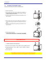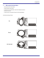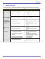
1
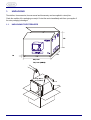
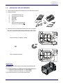
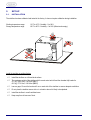
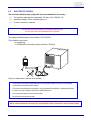
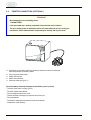
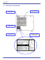
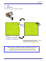
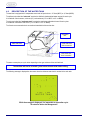
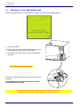
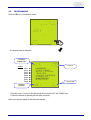
User Manual
Water Steam Sterilizer
LISA MB17/22 201 10 AEN REV. 9
SUMMARY
1.
UNPACKING
1.1.
1.2.
2.
SET-UP
2.1.
2.2.
2.3.
3.
4.6.
4.7.
4.8.
4.9.
Main menu
Description of the water tank
Filling of the main water tank
Draining of the used water tank
Programming
4.5.1. Selecting a language
4.5.2. Programming the name of the doctor / surgery
4.5.3. Programming the date and time
4.5.4. Programming the printer
4.5.5. Adjusting the brightness of the touch screen
4.5.6. Programming the stand-by mode
4.5.7. Maintenance program
4.5.8. Service program
CYCLE SELECTION
4.6.1. Cycle table
4.6.2. Selection – start of the cycle
4.6.3. Cycle procedure
4.6.4. Copies of cycle printouts
Manual stop
Cycle data information
Cycle data summary (end of cycle)
MESSAGES
ALARMS
6.1.
7.
Front view of the sterilizer
Rear view of the sterilizer
USE
4.1.
4.2.
4.3.
4.4.
4.5.
5.
6.
Installation
Electricity supply
Printer connection (optional)
DESCRIPTION
3.1.
3.2.
4.
Unpacking the sterilizer
Unpacking the accessories
Description of the alarms
USER MAINTENANCE
7.1.
7.2.
7.3.
7.4.
7.5.
7.6.
7.7.
Maintenance program
Cleaning the door seal
Cleaning the chamber, trays and tray holder
Cleaning the external parts
Replacing the bacteriological filter
Cleaning the water tanks
Replacing the door seal
8.
SERVICING CONDUCTED BY THE APPROVED TECHNICIAN
9.
BREAK-DOWN GUIDE
ANNEX 1
ANNEX 2
ANNEX 3
ANNEX 4
ANNEX 5
ANNEX 6
ANNEX 7
ANNEX 8
TECHNICAL CHARACTERISTICS
PREPARATION OF THE LOAD
MAINTENANCE OF DYNAMIC INSTRUMENTATION
BOWIE & DICK TEST
HELIX TEST
VACUUM TEST
WATER QUALITY
ACCESSORIES
1
User manual
RECOMMENDATIONS – SAFETY
The purpose of this user manual is to provide you with all the information you need in order to ensure:
ព A proper installation and set-up.
ព Optimal use.
ព A safe and reliable operation.
ព A regular and correct servicing requirements.
DECLARATION OF CONFORMITY
The Lisa sterilizer MB 17/22 is a Medical device class IIb, in accordance with rule 15 - Appendix IX of the
European Directive 93/42/CEE.
The sterilizer has been developed, produced and tested in accordance with the new European Norm relative to
small water steam sterilizers : EN 13060, and with the applicable safety norms (see appendix 1).
You will find enclosed a declaration of conformity and a warranty card specific to your sterilizer.
CONFORM USE:
The sterilizer must be used only for the purpose for which it was intended: the steam sterilization of solids, textiles
and hollow items unwrapped, single or double wrapped.
This symbol draws attention to the user manual.
To disregard the instruction given in this manual, the incorrect use and the
unauthorised disassembly of the sterilizer clears the manufacturer,
W&H l STERILIZATION of responsibility for warranty and any other claim.
This symbol is visible on the front of the device under the door handle.
It recommends attention be paid to the high temperatures associated
with the chamber, the door and the area around the door handle.
The documentation and diagrams used in this manual are the property of W&H l STERILIZATION, all rights
reserved. The photocopying, even in part, of the text or illustrations is forbidden.
We reserve the right to modify the sterilizer in pursuit of our aim to improve our equipment and keep
abreast of technology.
User manual
2
GENERAL RECOMMENDATIONS – SAFETY
The user is responsible for operating and servicing the sterilizer in accordance with the instructions
listed in this manual.
The sterilizer has not been designed for the sterilisation of liquids.
The sterilizer has not been designed to operate in the presence of gas or explosive vapours.
The chamber is automatically heated to 110°C as soon as the sterilizer is switched on.
The trays and the load will still be hot at the end of each cycle. Use the tray holder to remove each tray
from the chamber.
Comply with the maximum weight specified, having been tested and validated for each load type (see §
4.6.1.) by W&H l STERILIZATION in order to ensure smooth operation and effective sterilization.
Do not remove the instruction plate or any label from the sterilizer.
Do not pour water or any other liquid over the sterilizer.
Unplug the mains lead before inspecting or servicing the machine.
Repairs and maintenance must only be carried out by an approved technician using only original spare
parts.
In case of transport, drain both water tanks completely (§ 4.3 and 4.4), allow the sterilization chamber
to cool down and preferably use the original packaging.
Compliance with the instructions in this manual ensures safe operation.
3
User manual
1.
UNPACKING
The sterilizer, the accessories, the user manual and the warranty card are supplied in a sturdy box.
Check the condition of the packaging on receipt. Contact the carrier immediately and inform your supplier if
the outer packaging is damaged.
1.1.
UNPACKING THE STERILIZER
48
m
0
9
2
5
,
54
10
m
5
,0
9
6
64,5 cm
74,5 cm (MB22)
49Kg (MB17)
56 kg (MB22)
User manual
4
4,25 cm
1.2.
UNPACKING THE ACCESSORIES
Open the door and remove the accessories from the sterilization chamber.
Check the contents:
5 anodised aluminium trays
Reversible rack for 3/5 trays
Tray holder
Drain tube
Mains cable
Funnel
User manual and warranty card
Declaration of conformity
1
2
4
6
3
5
7
Insert the rack into the sterilization chamber and click it into position.
The rack is reversible and can be positioned to take either:
5 trays horizontally / 3 cassettes vertically
CLICK
90°
or
3 trays / cassettes horizontally.
Usable space:
This equates to the usable volume of the chamber accommodating the
sterilizable load.
This volume is equivalent to a parallel pipe with the following dimensions:
L: 195 mm, H: 205 mm, W: 300 mm, i.e. 12 litres (MB17)
L: 195 mm, H: 205 mm, W: 400 mm, i.e. 16 litres (MB22).
This volume is identical for all cycles and all types of load.
5
User manual
2.
SET-UP
2.1.
INSTALLATION
The sterilizer has been calibrated and tested in the factory. It does not require calibration during installation.
Working temperature range:
Storage temperature range :
10°C to 40°C / Humidity : 0 to 90%.
-20°C to 60°C / Humidity : 0 to 90% (Water tanks empty).
Install the sterilizer as outlined below:
ព
ព
Install the sterilizer on a flat and level surface.
ព
ព
ព
ព
Leave a gap of 5 cm at the back and 2 cm on each side of the sterilizer to ensure adequate ventilation.
The maximum weight of the sterilizer with the main water tank full and the chamber fully loaded is:
57,0 kg, 129.4 N/m², 140 N/foot (MB17)
66.5 kg, 177.3 N/m², 160 N/foot (MB22)
Do not place the sterilizer near a sink or in a location where it is likely to be splashed.
Install the sterilizer in a well ventilated room.
Keep away from all sources of heat.
User manual
6
2.2.
ELECTRICITY SUPPLY
The electrical installation must comply with the current standards in the country.
ព The electricity supply must be single phase 230 volts ±10%, 50/60Hz, 10A.
ព
ព
Installation category / Mains overload category = II
An earth connection is essential.
The sterilizer must be connected to an electrically earthed plug.
Use only the mains cable delivered with the sterilizer.
The maximum absorbed power of the sterilizer is 2100 W (9,2A).
The installation must include:
- an earthed plug.
- a 10A differential circuit breaker with a sensitivity of 30mA (2).
2
+
Plug in the mains cable to the back of the sterilizer.
Check that the serviceable voltage specified on the name plate located on the back of the sterilizer
corresponds to the supplied mains voltage.
The overall electrical safety of the sterilizer is only guaranteed if the sterilizer is appropriately earthed.
If unclear, have the installation checked by a qualified electrician.
Do not plug other equipment into the same socket.
Do not bend or twist the mains cable.
W&H l STERILIZATION does not accept any responsibility if these instructions are not complied with.
7
User manual
2.3.
PRINTER CONNECTION (OPTIONAL)
Attention !
We recommend to use the following printer:
- Custom DP40H.
It has been tested and is perfectly compatible with the sterilizer and its software.
The use of another printer is undertaken with the full responsability of the user, clearing the
manufacturer, W&H l STERILIZATION of responsability for warranty and any other claim.
Connect the printer cable to the 25 pin parallel port socket at the back of the sterilizer.
Cable length should not exceed 2 metres.
Plug in the printer mains cable.
Switch ON the printer.
Switch ON the sterilizer.
Select the printer type (§ 4.5.4.).
All the information needed to document the sterilization cycles is printed:
- The name of the Doctor / surgery (§ 4.5.2.).
- The serial number of the sterilizer.
- The chronological number of the cycle.
- The date and time at the beginning and at the end of the cycle.
- The cycle selected.
- The duration, temperature and pressure of the various phases.
- Comments on cycle efficiency.
User manual
8
3.
DESCRIPTION
3.1.
FRONT VIEW OF THE STERILIZER
Touch screen
Door
Service door
Main switch / circuit breaker *
Switch ON/OFF of the sterilizer.
Use this switch to interrupt a cycle
only in the case of a noted defect.
9 pin serial port
For technical department only.
* Replaces the fuses.
Used water tank
drain connection
Main water tank
drain connection
Bacteriological filter
9
User manual
3.2.
REAR VIEW OF THE STERILIZER
Condenser ventilation
25 pin printer port
Compliance plate
Mains plug socket
User manual
Connection for external
used water drainage
10
4.
USE
4.1.
MAIN MENU
Activate the mains switch, the selection screen appears.
Manual
stand-by
Cycle selection
(§ 4.6.2.)
Access to sub
menus (§ 4.5.)
If the sterilizer is not used for a certain period of time, it
will automatically go into stand-by mode.
Stand-by mode time is programmable (§ 4.5.6.).
When the sterilizer is switched ON, the chamber is automatically heated to 110°C.
Pre-heating starts from room temperature and takes approximately 10 minutes.
It is nevertheless possible to select and start a cycle before the end of pre-heating.
11
User manual
4.2.
DESCRIPTION OF THE WATER TANK
The sterilizer is equipped with 2 independent water tanks of equal volume - 3.5 litres (MB17) or 4,5 litres (MB22).
The left tank also called the "main tank" contains the distilled or demineralized water required for each cycle.
It is fitted with 2 level sensors, minimum (0.5 l) and maximum (3.5 l on MB17 or 4.5 l on MB22).
The right tank called the "used water tank" contains the used water collected at the end of each cycles.
It is fitted with a maximum level sensor (3.5 l on MB17 or 4.5 l on MB22).
The 2 tanks are connected to drain connections located behind the service door.
Used water
tank
Main water tank
Used water tank
drain connection
Main water tank
drain connection
The water consumption per cycle varies depending on the type and mass of the sterilized load.
The sterilizer will run for at least 8 cycles before the main tank needs refilling.
The following message is displayed on the screen when the minimum water level is reached in the main tank:
FILL THE
WATE R TAN K
While the message is displayed, it is impossible to run another cycle.
The selection button has disappeared !
User manual
12
4.3.
FILLING OF THE MAIN WATER TANK
Attention !
Use only high quality distilled or demineralized water (see Annex 7).
Remove the main water tank cap located on the top of the sterilizer …
…Fill the tank with approx. 3 litres on MB17 (or 4 litres on MB22) of water...
…Once the tank is almost full, an audible tone will be heard.
When you hear the tone proceed carefully. You must stop
filling as soon as the water level reaches the lower edge of the
opening to the water tank.
The water from the main tank (3 litres on MB17 or 4 litres on MB22) has been used for a series of
cycles.
This water has been drained off and stored in the used water tank which will be full.
While the main tank is re-filled, the used water tank must be drained in the meantime (see § 4.4.).
If the sterilizer is not used for more than 3 days, both water tanks must be
completely drained in order to avoid alga growth or any other deposits.
13
User manual
4.4.
DRAINING OF THE USED WATER TANK
When the used water tank is full, it is impossible to run another cycle. The following message appears:
DRAIN THE
U S E D W AT E R TA N K
♦ Open the service door.
♦ Insert the drain tube into the quick coupling drain connection of
the used water tank (right) as shown in the diagram.
♦ Allow the entire contents of the tank to empty and discard the
used water.
NEVER RE-USE THE USED WATER !
Disconnect the drain tube by pressing the push button on the drain
connection.
In the meantime, while the used water tank is drained,
the main tank can be re-filled.
If the sterilizer is not used for more than 3 days, both water tanks must be
completely drained in order to avoid alga growth or any other deposits.
User manual
14
4.5.
PROGRAMMING
Press the "M" key on the selection screen…
…The program menu is displayed…
To exit the
program menu
Cursor UP
Consult:
§ 4.5.1.
§ 4.5.2.
§ 4.5.3.
§ 4.5.4.
§ 4.5.5.
§ 4.5.6.
§ 4.5.7.
§ 4.5.8.
➔
➔
➔
➔
➔
➔
➔
➔
LANGUAGE
USER NAME
D AT E / C L O C K
PR I N T E R
TOUCH SCREEN
S TA N D - B Y
MAINTENANCE
SERVICE
Cursor DOWN
Access to
sub-menu
… Place the cursor ">" in front of the desired sub-menu using the "UP" and "DOWN" keys.
Confirm the selection by pressing the sub-menu access key.
Refer to the relevant chapter for the sub-menu selected.
15
User manual
4.5.1. SELECTING THE LANGUAGE
To exit the
sub-menu
Cursor UP
Cursor DOWN
Selection
confirmation
4.5.2. PROGRAMMING THE NAME OF THE DOCTOR / SURGERY
Confirmation, exit
of the sub-menu
Alphabet
scrolling +
Alphabet
scrolling -
Letter selection
cursor to the right
Letter selection
cursor to the left
User manual
16
4.5.3. PROGRAMMING THE DATE AND TIME
It is essential to adjust the date and time especially if the sterilizer is connected to a printer. These parameters are
systematically printed at the beginning and at the end of the cycle report.
Place the selection cursors under the data that is to be adjusted. Increase or decrease its value, move the cursors
under the next value and repeat operation. Confirm the adjustment by pressing the "Ok" key.
Confirmation, exit of
the sub-menu
Increase
Cursors
Decrease
Control of selection
cursors
4.5.4. PROGRAMMING THE PRINTER
To exit the
sub-menu
Cursor UP
Cursor DOWN
Confirmation
of the selection
17
User manual
4.5.5. PROGRAMMING THE BRIGHTNESS OF THE TOUCH SCREEN
Darker
Lighter
Confirmation, exit
from the sub-menu
4.5.6. PROGRAMMING THE STAND-BY MODE
Exit from
the sub-menu
Cursor UP
Cursor DOWN
Confirmation
of the selection
User manual
18
4.5.7. MAINTENANCE PROGRAM
This screen shows the number of cycles remaining before replacement of the bacteriological filter (400), the door seal (1000)
as well as when general servicing (4000) is required. The three counters are decreased in value after each cycle.
When one of the counters reaches 0 a corresponding message appears at the bottom of the selection screen.
It is not possible to run a new cycle (the selection button will disappear) unless the reading of the message has been
confirmed by pushing the Ok icon. The counter is then automatically reset.
If one of the three operations is completed before the respective counter has reached 0 it is necessary to reset the counter
manually. Place the cursor in front of the operation with the icons UP and DOWN and reset it by pushing the Ok icon.
Exit from the sub-menu
Cursor UP
Cursor DOWN
Reset of the
selected counter
4.5.8. SERVICE PROGRAM
In this sub-menu it is possible to select and run the Bowie & Dick, Helix and air leakage/vacuum test cycles.
The diagnostic function is reserved for technical service personnel and requires an access code.
Exit from the
sub-menu
Cursor UP
Cursor DOWN
Confirmation of
the selection
19
User manual
4.6.
CYCLE SELECTION
4.6.1. CYCLE TABLE
STERILIZATION CYCLES
B CYCLE
B CYCLE
B CYCLE
B-STANDARD
B-PRION
B-STANDARD
134
134
121
TYPE OF CYCLE
TEST CYCLES
B&D/
HELIX TEST
VACUUM
TEST
Temperature
135.5°C
135.5°C
122.5°C
135.5°C
--
Pressure
2.16 bar
2.16 bar
1.16 bar
2.16 bar
-0.85 bar
4'
18'
15'
3'20
16'
Duration of the plateau
Duration of the drying phase
15'
15'
20'
4'
--
30' - 40’ (MB17)
32' - 52’ (MB22)
44' – 54' (MB17)
46' - 66’ (MB22)
50' – 60' (MB17)
48' - 68’ (MB22)
23' (MB17)
26' (MB22)
24' (MB17)
25' (MB22)
Full solid (Probes, tweezers, burs,…)
YES
YES
YES
Small porous items (gauze, cotton,…)
YES
YES
YES
Full porous : 80% of the usable space.
YES
YES
YES
TYPE OF LOAD
Total duration empty – full load
Hollow A (handpieces, forceps, scissors,)
YES
YES
YES
Hollow B (vacuum tips,…)
YES
YES
YES
Unwr., bagged, single/double wrapped
YES
YES
YES
Max mass of the load : Solid / Porous
4.5 / 1.5 kg (MB17)
6.0 / 2.0 kg (MB22)
4.5 / 1.5 kg
(MB17)
6.0 / 2.0 kg
(MB22)
4.5 / 1.5 kg (MB17)
6.0 / 2.0 kg (MB22)
Empty
Load: The 3 Class B cycles can sterilize and dry all type of loads: full solid, porous, hollow A, hollow B,
plastics, rubber, etc. unwrapped, bagged, single and double wrapped, but :
Instructions given by the respective manufacturers must be followed in each case.
For guaranteed sterilization, never exceed the maximum load weight validated by
the manufacturer.
Test cycles
See annex 4, 5 & 6
All the cycles have the same profile:
Only the duration of the plateau time, the drying time and the temperature (121°) vary.
Pressure (bar)
Duration
D2
D1
PV1
PV2
PV3 PV4
PP1 PP2
PP3 PP4
PV5
PV6
User manual
PR
PP5
Fractionated pre-vacuum
Legend:
PV1..6 : Vacuum pulse
PR : Process
PPh
D4
D3
D6
D5
D8
D7
D9
DVs
Plateau time
End
D10
VEN
LEV
DVe
Pulsed vacuum drying
PP1..5 : Pressure pulse
DV : Vacuum drying
20
PPh : Pressure pulse and heating
VEN : Ventilation
LEV : Levelling
4.6.2. SELECTION – START OF THE CYCLE
Exit, if necessary, from the stand-by mode…
…Enter cycle select menu…
Exit and return to
selection screen
Cursor UP
Cursor DOWN
Confirmation of
the selection
Position the cursor in front of the required cycle.
Confirm your selection by pressing the "OK" key.
Start the selected cycle.
21
User manual
4.6.3. CYCLE PROCEDURE
The following information is displayed during the cycle:
Date
Time
Access to technical
data ➫ § 4.8
Selected cycle
N° of the cycle
Temperature
Pressure
Manual stop ➫ § 4.7
Current phase
Total duration
You can access the technical parameters at
any time by pressing the "Info" icon (see §
4.8.).
If needed, the cycle can be interrupted by
pressing the "STOP" icon for 2 seconds.
An audible tone will confirm your request.
This is followed by a 2-minute interval
necessary to reinitialise the system and
revert to atmospheric pressure in the
chamber (see § 4.7.).
END OF THE CYCLE
Reference to
cycle data ➫ § 4.9
Date
Time
Selected cycle
N° of the cycle
"Load sterile"
Temperature
Pressure
Opening of
the door
End of the cycle
Total duration
Comment:
At the end of the cycle, the micro-processor
analyses the temperature, pressure and
duration of all the phases in order to confirm
whether or not sterilization has occurred.
After reading the comment, you can open the
door by pressing the corresponding key.
If the door remains locked at the end of the cycle, the vacuum pump remains in operation. Every
10 minutes the pump will run for 40 seconds in order to ventilate the chamber and load preventing
the build up of moisture. This operation continues until the temperature of the chamber falls below
60°C.
Before the door is opened, it is possible to access the cycle data by simply pressing the "Info" icon
(see § 4.9.).
4.6.4. COPIES OF CYCLE PRINTOUTS
It is possible to get copies of the last cycle printout prior to door opening.
Back to previous
screen without
printing
Increase the
quantity (1-9)
COPIES OF LAST
CYCLE PRINTOUT
Decrease the
quantity (1-9)
PRINTING
Press
….Select the quantity needed: 1 to 9,
…
Print by pressing
User manual
22
4.7.
MANUAL STOP
If needed, the cycle can be interrupted at any moment by pressing the "STOP" key for 2 seconds. An audible tone will
confirm the request…
2”
MANUAL STOP
PLEASE WAIT
LOAD NOT
STERILE
…This is followed by a phase of approximately 2 minutes, required to reinitialise the system and return the chamber to
atmospheric pressure.
The door can be opened when the "Exit" key appears on the display at the end of this phase.
The load is not sterile and the cycle must be repeated !
If the cycle is interrupted after the PR phase (plateau period), following message will be
displayed and printed :
!! LOAD STERILIZED, BUT NOT DRIED !!
!!
FOR IMMEDIATE USE ONLY
23
!!
User manual
4.8.
CYCLE DATA INFORMATION
You can access the technical data at any time during the cycle by pressing the "Info" icon.
..The following data will be displayed…
Date
Time
Chamber pressure
T° calculated/Pressure
T° of the steam
T° chamber heater
T° steam generator
Phase in progress
Duration of the phase
Exit and return to the current cycle screen.
User manual
24
4.9.
CYCLE DATA SUMMARY (end of cycle)
At the end of the cycle, before opening the door, the "Info" icon gives access to the technical data summary of the
completed cycle.
The first screen lists the pressure and duration
of each phase until the process...
( PV- vacuum pulse / PP- pressure pulse )
Exit and return to
"cycle end" screen
…The second screen indicates the temperature
and pressure relating to the sterilization phase:
Measured pressures : begin. / end / min. / max.
Measured temperatures: begin. / end / min. / max.
25
User manual
5.
MESSAGES
A certain number of messages can appear at the beginning or at the end of the cycle.
This is merely information and not an alarm. The user can continue to operate the sterilizer with complete confidence.
During a cycle, the micro-processor continuously analyses all the parameters. The cycle would be interrupted immediately
and an alarm displayed, if there was a concern with the sterilization quality (see § 6).
Message display
FILL THE
WATE R TAN K
Messages list:
Message
FILL THE
WATER TANK
DRAIN THE
USED WATER TANK
CLOSE
THE DOOR
DOOR LOCKING
PROBLEM
Ttheo/Tsen DIFF
IN STERL. PHASE
Temp FLUCTUATION
IN STERIL. PHASE
User manual
Description
Action
The minimum water level has been reached in the
main tank.
Fill the main tank using distilled or demineralised
water as described in § 4.3.
The maximum level of the used water tank has been
Drain the tank described in § 4.4.
reached.
The door is not closed properly.
Close the door.
The door could not be locked properly
Control (clean) the door seal.
Monitor. ☎ Service if the message persists.
During sterilization phase: 2°C difference between
measured and theoretical temperatures (deducted
from the pressure).
The sterilization grade is satisfactory because, at
the beginning of the cycle, the micro-processor
evaluates the vacuum level and stops the cycle if it
is inadequate.
Monitor. ☎ Service if the message persists.
The sterilization grade is satisfactory because, at
During sterilization phase: fluctuation by +/- 1,5°C of the beginning of the cycle, the micro-processor
the measured and/or the theoretical temperatures
evaluates the vacuum level and stops the cycle if it
(deducted from the pressure).
is inadequate.
Monitor. ☎ Service if the message persists.
26
6.
ALARMS
The micro-processor continuously analyses all the cycle parameters.
If there is any doubt regarding sterilization efficiency, the cycle is immediately interrupted and an alarm displayed.
This is followed by a phase of approximately 2 minutes required to reinitialise the sterilization system and to return the
chamber to atmospheric pressure. The load is not sterile and the cycle must be repeated !
The alarm screen appears…
Press the "OK" icon at the end of the re-initialisation
phase to confirm the reading of the alarm.
PLEASE WAIT
Code of the alarm /
interrupted phase
see table §6.1.
LOAD NOT
STERILE
Opening of the door…
…and return to stand-by mode.
If the cycle is interrupted after the PR phase (plateau period), following message will be
displayed and printed :
!! LOAD STERILIZED, BUT NOT DRIED !!
!!
FOR IMMEDIATE USE ONLY
!!
27
User manual
6.1.
DESCRIPTION OF THE ALARMS
N°
Description
Action
Mains
Mains failure or significant fall in voltage occurred
A01 during the cycle.
The load cannot be considered sterile.
The cycle must be repeated.
Sterilization chamber
The time spent to reach the sterilization plateau is
Clean the door seal, repeat the cycle.
If the problem persists ℡ service.
The temperature of the chamber heating element
Repeat the cycle.
If the problem persists ℡ service.
The temperature of the chamber heating element
Repeat the cycle.
If the problem persists ℡ service.
A10 too long (overload, leaks, etc.).
A11 is above the nominal value.
A12 is below the nominal value.
During the sterilization process, the pressure
A13 measured in the chamber is above the maximum
threshold.
During the sterilization process, the pressure
A14 measured in the chamber is below the minimum
threshold.
Repeat the cycle.
If the problem persists ℡ service.
Repeat the cycle.
If the problem persists ℡ service.
During the sterilization phase, the temperature of
Repeat the cycle.
If the problem persists ℡ service.
During the sterilization phase, the temperature of
Repeat the cycle.
If the problem persists ℡ service.
A15 the steam is below the minimum threshold.
A16 the steam is above the maximum threshold.
The temperature sensor of the chamber heating
A17 element is broken or disconnected.
The internal temperature sensor (steam) of the
A18 chamber is broken or disconnected.
A19 Air Detection system – Leak found in PPH phase
A20 Air Detection system – A.D. problem
℡ service
℡ service
Repeat the cycle.
If the problem persists ℡ service.
Repeat the cycle.
If the problem persists ℡ service.
Steam generator
The temperature of the steam generator is above
Repeat the cycle.
If the problem persists ℡ service.
The temperature of the steam generator is below
Repeat the cycle.
If the problem persists ℡ service.
A21 the maximum threshold.
A22 the minimum threshold.
The temperature sensor of the steam generator is
A23 broken or disconnected.
User manual
℡ service
28
DESCRIPTION OF THE ALARMS (continue)
N°
Description
Action
Vacuum pump
During a vacuum phase, the maximum achieved
Clean and check the door seal (§ 7.2.), repeat the
cycle. If the problem persists ℡ service.
During a vacuum phase, the maximum achieved
Clean and check the door seal (§ 7.2.), repeat the
cycle. If the problem persists ℡ service.
A31 vacuum is not lower than – 0.20 bar.
A32 vacuum is not lower than – 0.50 bar.
The global vacuum level obtained after 5 pulses is
Clean and check the door seal (§ 7.2.), repeat the
A33 not sufficient. The calculated additional 6th pulse is cycle. If the problem persists
℡ service.
impossible to obtain (outside limits).
The last 10 cycles have required a 6th additional
A34 vacuum pulse.
Sterilization is guaranteed because the additional
6th pulse ensures the global vacuum level has been
obtained, ℡ service for control.
Door locking
A52
1) The door locking system is blocked during
opening and closing phases.
2) The door locking switch is open during the
cycle.
℡ service
Electro-valves
The pressure does not exceed – 0.70 bar,
℡ service
A63 2 minutes after the end of a vacuum phase.
29
User manual
7.
USER MAINTENANCE
A distinction must be made between two levels of maintenance, that performed regularly by the user and preventive
maintenance carried out by an approved technician (§ 8).
Remove the mains cable before examining the sterilizer.
7.1.
MAINTENANCE PROGRAM
Frequency /
Weekly
N° of
cycles
50
Spare
number
Description
Cleaning the door seal.
-
§ 7.2.
Cleaning the chamber, the trays and the rack.
-
§ 7.3.
Cleaning the external surfaces.
-
§ 7.4.
W322400X
§ 7.5.
-
§ 7.6.
F460503X
§ 7.7.
-
§ 8.
Operation
Every 3 months
400
Replacing the bacteriological filter.
Every 6 months
1000
Cleaning both water tanks.
Every year
1000
Replacing the door seal.
* Every 3 years.
4000
Servicing by an approved technician.
*Refer to the legislation and instructions for each individual country.
The maintenance sub-menu (§ 4.5.7.) indicates the number of cycles remaining before replacement of the
bacteriological filter, the door seal and when general servicing is required. The three counters are decreased in value
after each cycle.
When one of the counters reaches 0 a corresponding message appears at the bottom of the selection screen.
It is not possible to run a new cycle (the selection button will disappear) unless the reading of the message has been
confirmed by pushing the "OK" icon. The counter is then automatically reset.
If one of the three operations is completed before the respective counter has reached 0 it is necessary to reset the
counter manually. Place the cursor in front of the operation with the icons UP and DOWN and reset it by pushing the
"OK" icon.
Exit of the sub-menu
Cursor UP
Cursor DOWN
Reset of the
selected counter
User manual
30
7.2.
CLEANING THE DOOR SEAL
Clean the door seal and the porthole with a lint free cloth saturated with alcohol.
The porthole can also be cleaned with a non-abrasive detergent.
7.3.
CLEANING THE CHAMBER, TRAYS AND TRAY HOLDER
Remove the trays from the chamber.
Disconnect and remove the rack.
Clean the chamber with a damp sponge moistened with a detergent or scouring agent if necessary.
Rinse with a damp sponge to remove all traces of the cleaning agent.
Apply the same procedure for the rack, trays (cassettes).
Ensure that you clean all around the sterilizer chamber.
Do not bend or damage the temperature sensor at the bottom of the chamber.
Never use disinfectants to clean the chamber.
7.4.
CLEANING THE EXTERNAL PARTS
Clean the external parts with a damp cloth and mild detergent.
Never use scouring agents or highly abrasive products.
Do not use copious amounts of water to wash the sterilizer as this may damage the
electrical components and safety mechanisms.
Take care not to scratch the plastic film in front of the touch-screen.
7.5.
REPLACEMENT OF THE BACTERIOLOGICAL FILTER
Open the service door.
Unscrew the bacteriological filter by hand (anti-clockwise).
Insert and manually screw the new filter into position
31
User manual
7.6.
CLEANING THE WATER TANKS
Completely drain both water tanks (main and used water tank).
Open the service door.
Insert the drain tube into the quick coupling drain connection of
the used water tank (right). Allow the entire contents of the tank
to empty and discard the used water.
Disconnect the drainage hose by pressing the push-button on the
drain connection.
+
Insert the drain tube into the quick coupling drain connection of
the main water tank (left). Allow the entire contents of the tank to
empty.
Disconnect the drainage hose by pressing the push-button on the
drain connection.
Fill both reservoirs each with:
2.8 litres of demineralised water + 0.2 litres of 90% alcohol (MB17)
3.7 litres of demineralised water + 0.3 litres of 90% alcohol (MB22)
DO NOT RUN A CYCLE !
Allow the solution to sit for 30 minutes.
Drain both tanks and discard the 3 litres on MB17 (4 litres on MB22) of solution.
Fill the main tank with 3 litres on MB17 (4 litres on MB22) of distilled or
demineralised water.
Run an empty cycle.
If the sterilizer is not used for more than 3 days, both water tanks must be
completely drained in order to avoid alga growth or any other deposits.
User manual
32
7.7.
REPLACING THE DOOR SEAL
Fully open the door of the sterilizer.
Remove the door seal by hand.
Carefully clean the seal seat with a cotton bud moistened with alcohol.
Moisten the new seal.
Insert the seal in the sequence illustrated in the following diagrams:
Insert the seal starting as follows:
Up
Down
Left and right.
33
User manual
8.
SERVICING CONDUCTED BY THE APPROVED TECHNICIAN
Service is essential to continued effective sterilization.
We recommend servicing by an approved technician every 3 years or 4000 cycles.
Check list:
Replacement of the 5 Solenoid valves.
Replacement of the vacuum pump membrane kit.
Replacement of the water filter.
Replacement of the steam generator heating element.
Cleaning the sterilization chamber.
Cleaning the sterilization chamber filter.
Cleaning the steam generator filter (EV5).
Check of the pneumatic connections.
Check the electrical connections.
Check the door locking system.
Check the 2 pressure safety valves.
Check the safety systems.
User manual
34
9.
BREAK-DOWN GUIDE
The list below of problems is limited because most defects and incidents are covered in messages (§5) and alarms (§6).
PROBLEMS
POTENTIAL CAUSES
The main switch or network circuit
breaker is open (OFF).
No voltage at the socket.
The mains cable is not properly
connected.
Activate the main switch or network circuit
breaker (ON).
Check the electrical circuit.
Plug in the cable.
Water leaking at the front of the sterilizer. Leaks via the door seal.
Punctured or disconnected hose.
Clean the door seal (§ 7.2.)
℡ service for control.
At the end of the
cycle, water remains
within the chamber and the load is not
perfectly dry.
Poorly levelled machine.
The sterilizer must be installed on a level
surface.
Comply with the maximum mass for each
type of load (§ 4.6.1.).
Follow the recommendations listed in
Annex 2.
The sterilizer
remains switched
OFF.
Humidity in the
packaging or in the
load.
Oxidation or spots
on instruments.
Instruments turning
brown or black.
SOLUTIONS
Overloaded chamber.
Load incorrectly positioned.
Overloaded chamber.
Comply with the maximum load
(§ 4.6.1.).
Follow the recommendations listed in
Annex 2.
Load incorrectly positioned.
Use of poor quality water or water
containing chemical substances.
Organic or chemical residues on the
instruments.
Contact between various materials.
Calciferous deposits on the chamber.
Drain both water tanks (§ 4.2. / 4.3. / 4.4.).
Use good quality water (described in
Annex 9).
Clean and rinse all instruments with
demineralised water (Annex 2).Remove
all traces of disinfectants.
Interleave with tissues.
Clean the chamber.
Incorrect temperature selected.
35
Consult the table in § 4.6.1.
Follow the instrument manufacturer’s
instructions.
User manual
Annex 1
TECHNICAL CHARACTERISTICS
Electricity supply
Single phase 230 VAC ±10% – 50/60Hz – 10A
Sterilizer:
Name plate situated on the back side:
Working temperature / Humidity
Storage temperature / Humidity
Min. atmospheric pressure
Nominal voltage :
Max. absorbed power :
Max. current :
Dimensions overall :
Max. space required :
Clutter of the door movement :
Weight empty :
Max. mass in working condition fully loaded :
Max. heat output :
Max. noise level :
10°- 40°C / 0-90%.
-20°- 60°C / 0-90% (empty)
0,5 bar
230 V
2100 W
9,2 A
W : 445mm / H : 410mm / D : 520mm (MB17) – 620mm (MB22)
W : 485mm / H : 460mm / D : 570mm (MB17) – 670mm (MB22)
W : 360mm / H : 400mm / D : 360mm
49 kg (MB17) or 56 kg (MB22)
129.4 N/m² (140 N/ foot) for MB17 or 177.3 N/m² (160 N/ foot) for MB22)
3000 KJ/hr
< 50dB
Name plate on the steam generator:
Steam generator
Steam generator
Jahr/Year
Power / Voltage :
Max. pressure / Max. temperature :
Safety overpressure valve :
1700 W / 230 VAC
4 bar / 150°C
5 bar
Name plate on the chamber:
Sterilization chamber
Power / Voltage :
Max. pressure / Max. temperature :
Safety overpressure valve :
Total volume :
Usable space (identical for all cycles) :
Bacteriological filter :
1000 W / 230 VAC
2,4 bar / 138°C
2,4 bar
17 l. Ø:250mm / Depth:350mm (MB17)
21 l. Ø:250mm / Depth:450mm (MB22)
12 l. W:195mm / H:205mm / D:300mm (MB17)
16 l. W:195mm / H:205mm / D:400mm (MB22)
0.3 µm
1999
Zul. Warmeleistung / Max.Power
Zul. Betriebsüberdruck / Max. Pressure
Wasserinhalt / Water volume
Double tank / Autonomy :
Sterilizer chamber
Kammer inhalt / Chamber volume
LISA
991230000
1 KW
2,4 Bar
17 L
Zul. Betriebstemperature / Max. T°
138°C
Jahr/Year
1999
Zul. Betriebsüberdruck / Max. Pressure
Conform to EN 13060 annex C
0,2 l / 0,35 l (full porous load) on MB17
0,3 l / 0,50 l (full porous load) on MB22
Min 8 cycles (full porous load)
Parallel printer port
Miscellaneous
Fully micro-processor driven and controlled / touch screen
Mains filter / 2KV over tension filter.
Programmable stand-by mode.
STERILIZER CLASS B conform with following directives and norms :
User manual
Medical Device Directive (MDD)
Pressure Equipment Directive (PED)
Small steam sterilizer.
Laboratory equipment – Safety requirements.
Laboratory equipment – Specific instructions for steam sterilizer
Electrical equipment for measurement, control and laboratory use - EMC requirements
36
Model
SN
Zul. Warmeleistung / Max.Power
Connections
93/42/EEC
97/23/EEC
EN 13060
EN 61010-1
EN 61010-2-040
EN 61326
LISA
991240000
1,7 KW
4 Bar
0,05 L
Prüfüberdruck und Ausführung entsprechen der
Dampfkesselverordnung. / Overpressure tests and
development are conform to vessel standards.
Distilled water (or demineralized ) :
Water quality :
Min. / Max. consumption :
Model
SN
Annex 2. PREPARATION OF THE LOAD
1.
Cleaning of the instrument
The instruments to be sterilized must be clean and free from all types of residue such as fragments, dentine and
blood, etc. These substances can damage the objects placed in the trays and even the sterilizer itself.
♦ Clean the instruments immediately after use. Follow the manufacturer’s instructions when using an ultrasonic
cleaner.
♦ Remove all traces of disinfectant from the product as this may cause corrosion on heating. Rinse thoroughly,
then dry.
♦ Lubricate in accordance with the manufacturer’s instructions.
2.
Preparation of the trays
♦ For each program, do not exceed the maximum load which has been set, tested and validated by the
manufacturer and for which a perfect sterilization is guaranteed.
♦ Always use the rack to allow adequate steam circulation between the trays.
♦ Do not overload the trays in order to improve sterilization and drying.
♦ Place the cassettes in the vertical position (if possible) to ensure thorough drying.
♦ Place the items in such a way so as to allow the steam to circulate properly.
♦ Empty containers or non perforated trays must be placed upside down to prevent accumulation of water.
♦ Items made from different materials (stainless steel, carbon, etc.) must be placed on separate trays.
♦ Where instruments are manufactured from carbon steel, paper should be placed between them and the sterilizer
tray.
♦ Sterilize instruments in the open position, eg. forceps.
♦ In the case of wrapped items, use porous packaging to facilitate good steam penetration and drying (e.g.
nylon/paper sachet for autoclave).
Tubes
♦ Rinse, drain and dry after washing.
♦ Place the tubes on a tray allowing the ends to remain open. Do not bend.
Packets
♦ Place the packets in the vertical position, leaving a space between each one. Do not allow them to come into
contact with the walls of the sterilization chamber.
Wrapped material
♦ Sachets should be placed on trays, leaving a space between each one. Position with paper side upwards.
The sterilizer detects and amplifies errors which occur upstream from sterilization
37
User manual
Annex 3
1.
MAINTENANCE OF DYNAMIC INSTRUMENTATION
External disinfecting
This procedure prevents the risk of infection during cleaning and maintenance.
♦ Wear gloves.
♦ Dampen the instrument with a non-corrosive disinfectant (pH from 2.5 to 9) or with 70-80% ethyl alcohol.
♦ Comply with the disinfection reaction times recommended by the manufacturer.
Immerse or vaporise the instruments. Do not allow the disinfectant to come
into contact with the instrument, poor rinsing, etc.
Do not use cloths containing chlorhexidine or aldehydes.
DO NOT :
If any traces of disinfectant are left on the instruments, the latter will become corrosive when heated. This may cause
extensive damage during sterilization: oxidation, modification to the technical characteristics of seals, rubber, fibre
optics, etc.
2.
External cleaning
This procedure involves the removal of residues (blood, dentine, etc.) which adhere to critical areas such as spray
outlets, fibre optics, etc.
♦ Use a soft, damp brush and take care not to scratch the surface of the fibre optics.
♦ Remove from the item all traces of the disinfectant used prior to this cleaning phase. This product must only act
over a given time after which it may become aggressive for both instrument and sterilizer.
3.
Maintenance
Once the instrument has been disinfected, cleaned and is dry, free from residues, it must be lubricated before, not
after sterilization..
a) Manual lubrication with oil spray
♦ Check the condition of the O-ring on the spray insert. Replace if necessary.
♦ Purge the spray tubes by blowing air into the instrument.
♦ Lubricate using an oil aerosol in accordance with the manufacturer’s recommendations.
b) Automatic lubrication with Assistina: a more economical and more effective solution
♦ Assistina can clean and lubricate dynamic rotating instruments.
♦ The advantage of this equipment: simplified and effective cleaning and lubricating of the mechanical components.
♦ Automatic, optimal injected quantity of oil.
♦ Assistina also cleans and dries the spray tubes, preventing them from clogging.
4.
Packaging
In order to preserve sterility, rotating instruments should ideally be wrapped prior to sterilization.
The sterilizer detects and amplifies errors which occur upstream from sterilization
User manual
38
Annex 4: BOWIE & DICK TEST
The Bowie & Dick Test, also called the Brown Test, is representative of the small porous type load.
It comprises several sheets of paper and foam wrapped in a small packet in the middle of which there is a chemical
heat-sensitive indicator strip (physic-chemical test).
This test is used to validate the equipment performance in terms of textile load sterilization, i.e.:
Pre-vacuum efficiency and thus steam penetration.
Temperature and pressure parameters of the saturated steam during the holding time.
Pressure (bar)
2.16
The cycle profile is identical to that of other cycles with:
a temperature of 135,5°C .
a pressure of 2,16 bar.
a sterilization plateau of 3min 20 sec
guaranteeing a security margin.
a drying time cut to 4 min not to falsify the result.
Duration
End
D2
D1
PV1
PV2 PV3 PV4 PV5
PP1 PP2 PP3 PP4
PPh
PR
VEN
DVs
DVe
LEV
Carry out the test as follows:
♦ Place the Bowie & Dick Test (complete packet) on the lower tray of the chamber, with the label facing upwards.
♦ Select and start the Helix / B&D cycle from the "service" sub-menu.
LANGUAGE
USER NAME
D AT E / C L O C K
PR I N T E R
TOUCH SCREEN
S TA N D - B Y
MAINTENANCE
SERVICE
♦ Once the cycle is completed, open the door and remove the test. Caution: the packet will be very hot!
♦ Remove the indicator strip from the centre of the packet.
Correct result:
Incorrect result:
The radial strips have turned black
The central part is not the same colour as the edges.
The result is also incorrect, if the indicator is grey or silver (over-exposure, i.e. excessive temperature).
You can enter your name, the date, cycle number and sterilizer number on each test for filing purposes.
39
User manual
Annex 5
HELIX TEST
The Helix Test is the most complex representation of a hollow instrument load ( type A ).
Characteristics:
Length: 150 cm
Strip test
Internal diameter: 2 mm
Material : PTFE
This test is used to validate the equipment performance in terms of hollow instruments sterilization, namely:
Pre-vacuum efficiency, rapid and uniform steam penetration.
Temperature and pressure parameters of saturated steam during the holding time.
Pressure (bar)
2.16
The cycle profile is identical to that of other cycles with:
a temperature of 135,5°C
a pressure of 2,16 bar.
a sterilization plateau of 3 min 20 sec. guaranteeing a
security margin.
a drying time cut to 4 min not to falsify the result.
Duration
End
D2
D1
PV2 PV3 PV4 PV5
PP1 PP2 PP3 PP4
PV1
PPh
PR
Carry out the test as follows:
♦ Place a test strip inside the capsule.
♦ Close the capsule.
♦ Place the test on the lower tray in the chamber.
♦ Select and start the Helix / B&D cycle from the "service" under-menu.
VEN
DVs
LANGUAGE
USER NAME
D AT E / C L O C K
PR I N T E R
TOUCH SCREEN
S TA N D - B Y
MAINTENANCE
SERVICE
♦
♦
Once the cycle is competed, open the door and remove the test.
Caution the Helix Test will be very hot !
Open the capsule and remove the test strip.
Correct result:
Incorrect result:
The 4 spots on the strip have turned black.
User manual
Not all the spots have turned black.
40
DVe
LEV
Annex 6
VACUUM TEST
This test is used to validate the performance of the sterilizer in terms of leakage:
The efficiency of the vacuum pump.
The tightness of the pneumatic circuit.
Pressure
Duration
T1
T2
T3
P1
P2
P3
-0.65
-0.85
The profile of the cycle, specific for this test includes:
A vacuum phase up to P1 = - 0.85 bar.
A stabilisation period of 5' => T2. Reading of P2.
A testing period of 16'
=> T3. Reading of P3.
Carry out the test as follows:
♦ Select and start the Vacuum Test cycle from the "service" sub-menu.
LANGUAGE
USER NAME
D AT E / C L O C K
PR I N T E R
TOUCH SCREEN
S TA N D - B Y
MAINTENANCE
SERVICE
♦ The micro-processor makes the following calculation: P3 - P2. The result must be less than 0.02 bar *.
♦ Comments, positive or negative are displayed at the end of the test.
* IMPORTANT :
According EN13060 norm, the "AIR LEAKAGE / VACUUM TEST" requires a 13mbar (0,013bar) leak test
within a period of 10min. that is to say 1,3 mbar/min. The sterilizer pressure sensor is not 1mbar
(0.001bar) but 10mbar (0.01bar) accurate. A leak of 13mbar is therefore not measurable but only a
20mbar (0,02bar) one. The test period has proportionally been increased from 10 to 16min. so that a
leak test of 20mbar within 16min. that is to say 1,25 mbar/min is proven.
41
User manual
Annex 7
WATER QUALITY
The table below lists the quality of the water to be used for steam sterilization as taken from the new
European standard (EN 13060, Annex C)
Table C.1: Contaminants of feed water
FEED WATER
Evaporate residue
≤ 10 mg/l
Silicium oxide, SiO2
≤ 1 mg/l
Iron
≤ 0,2 mg/l
Cadmium
≤ 0,005 mg/l
Lead
≤ 0,05 mg/l
Rest of heavy metals, excluding iron,
cadmium, lead
≤ 0,1 mg/l
Chloride
≤ 2 mg/l
Phosphate
≤ 0,5 mg/l
Conductivity (at 20°C)
≤ 15 µs/cm
pH value
5 to 7
Appearance
colourless, clean,
without sediment
Hardness
≤ 0,02 mmol/l
NOTE 1: The use of water for steam generation with contaminants at levels exceeding those
given in this table can greatly shorten the working life of a sterilizer and can invalidate
the manufacturer's warranty or guarantee.
User manual
42
Annex 8
ACCESSORIES
DESCRIPTION
SPARE NUMBER
Printer: Custom DP40H/cable
A70010XX
Anodised perforated aluminium trays
18,5mm x 28,5mm
T523200X (MB17)
T523202X (MB22)
Reversible rack
F523002X (MB17)
F523006X (MB17)
Cassette holder
F523000X
Tray holder
F523001X
Drain tubing with quick coupling
S230900X
Mains cable
/
Funnel
F540902X
Bacteriological filter
W322400X
Door seal
F460503X
43
User manual
Manufacturer:
W&H Sterilization S.r.l
Italy, I-24060 Brusaporto (BG)
Via Bolgara, 2
t +39/035/66 63 000
f +39/035/50 96 988
wh.com
Importer: