1
TRACE32 Installation Guide
TRACE32 Online Help
TRACE32 Directory
TRACE32 Index
TRACE32 Installation .......................................................................................................................
TRACE32 Installation Guide .........................................................................................................
1
Prerequisites ...............................................................................................................................
6
Basic Concepts ..........................................................................................................................
7
TRACE32-ICD (In-Circuit Debugging) .......................................................................................
8
Host-based Interfaces
8
USB Interface (TRACE32-USB)
8
Ethernet Interface (TRACE32-NET)
9
Controller-based Interfaces
9
Minimal Manual Setup ................................................................................................................
Prerequisites and Recommendations for the Minimal Manual Setup
10
11
Copy the Required Files (USB and Ethernet)
12
USB Configuration
13
Set Up the Hardware (USB)
13
Install Drivers (USB)
14
Create the Configuration File (USB and NET)
Ethernet Configuration
15
16
Assign a Hostname to the TRACE32 Device (Ethernet)
17
Modify the Configuration File (Ethernet)
18
Re-configure the Hardware (Ethernet)
19
Identify the Peripheral File
20
TRACE32-ICE (In-Circuit Emulation) ........................................................................................
22
Legacy Host Interfaces
22
Parallel Interface (TRACE32-PAR)
22
Serial Interface (TRACE32-SER)
22
Fiber Optic (TRACE32-SER, TRACE32-NET)
22
SCSI Interface (TRACE32-SER, TRACE32-NET)
23
Host Interface Cards
23
Fiber Optic Interface (PC-ISA)
23
Fiber Optic Interface (PC-MCA)
24
Hardware Installation (TRACE32-ICE) ......................................................................................
25
Remove Modules
25
Add Modules
25
©1989-2014 Lauterbach GmbH
TRACE32 Installation Guide
1
System Memory (SCU/PODETH)
26
SCU16-MX2
26
SCU32-MX4
26
LEDs on TRACE32 Hardware Modules ....................................................................................
27
PowerTools
27
SCU32
33
SCU32-MPC
34
SCU32-MPC 100MBit
35
PODBUS Ethernet Controller
36
PODBUS Ethernet Controller/100
37
TRACE32-Interfaces ...................................................................................................................
TRACE32-USB
38
38
Connector (USB 3.x)
38
Connector (USB 2.0 and 1.x)
38
USB Interfaces (USB 3.x to 1.x)
38
TRACE32-ETHERNET
40
8P8C-Connector (T568A/B, ‘RJ45’)
40
AUI-Connector
40
Ethernet Interface
40
Selection of Transfer Protocol
41
TRACE32-PAR
42
Connector
42
Parallel Interface
42
TRACE32-SER
43
Connector
43
RS232 Interfaces
43
RS422-Interface
43
Fiber Optic Interface
43
Selection of Transfer Protocol
44
Selection of Interface
44
Asynchronous RS232/RS422 Driver
45
SASO
46
Connector
46
Fiber Optic Interface
46
Selection of Interface
46
SYSTEM SOFTWARE .................................................................................................................
Files and Directories
47
47
TRACE32 System Files
49
Multiple Systems on one Host
51
File config.t32
52
Parameters for the PBI Driver with LAUTERBACH Tools
54
Parameters for PBI Drivers (Software-Only)
58
©1989-2014 Lauterbach GmbH
TRACE32 Installation Guide
2
Software Installation ..................................................................................................................
Licensing Terms Glossary
62
63
General Licensing Terms
63
Terms for Floating Licenses with RLM
64
Floating Licenses
65
How To Install Floating Licenses - Overview
65
How To Upgrade Floating Licenses
65
License Management Server
66
Lauterbach Certificate
66
Lauterbach Daemons
66
How to get the RLM Host ID
67
License Client Setup
68
Floating License Pools
70
Software-Only License Types
71
License Pool Setup
72
Example Session
74
Caveats
76
MS-WINDOWS
77
Quick Installation for controller-based debugging
77
File CONFIG.T32
78
Fiber Optic Interface
78
Parallel Interface
79
Performance Tuning
80
Ethernet
81
Controller-based Ethernet setup
81
USB Interface
82
Screen/Windows
83
Printer
85
SUN/SPARC
86
Quick Installation
86
File config.t32
89
Ethernet Interface
91
SCSI Interface
92
RS232 Interface
94
Sunview
95
Motif
97
Terminal
102
Printer
102
HP-9000
103
Quick Installation
103
HP-UX 10.X
103
HP-UX 9.X and lower
106
File config.t32
109
©1989-2014 Lauterbach GmbH
TRACE32 Installation Guide
3
Ethernet Interface
110
SCSI Interface
111
RS232 Interface
111
Motif or CDE
112
Printer
113
PC_LINUX
114
Quick Installation
114
Preparations for the Ethernet Interface
118
REMOTE Interfaces ....................................................................................................................
119
Example OS/9 together with PC
120
Example VAX/VMS and Workstation
121
InterCom Interface ......................................................................................................................
122
Troubleshooting .........................................................................................................................
123
FAQ ..............................................................................................................................................
127
©1989-2014 Lauterbach GmbH
TRACE32 Installation Guide
4
TRACE32 Installation Guide
Version 11-Nov-2014
30-Jun-14
Added chapter “Floating Licenses” and updated CONNECTIONMODE=, see “Parameters
for the PBI Driver with LAUTERBACH Tools”.
14-Feb-14
Added description LEDs of PowerTools.
©1989-2014 Lauterbach GmbH
TRACE32 Installation Guide
5
Prerequisites
TRACE32 supports these host computers and operating systems:
Host
OS
Company
Comment
AXP-STATION
DIGITAL UNIX
DEC
AXP-STATION
VMS/AXP 1.5
DEC
Motif (SCU based
SW only)
Motif (SCU based
SW only)
HP-9000/700
HP-UX 8.0
HP
HP-9000/700
HP-UX 9.0
HP
HP-9000/700
HP-UX 10.X
HP
LINUX/PPC
MAC OS-X/X86
MAC OS-X/X86
LINUX
APPLE
APPLE
Motif/Lesstif
Motif
QT
PC
PC
PC
PC
PC
WINDOWS 2000
WINDOWS XP
WINDOWS VISTA
WINDOWS 7
LINUX
MICROSOFT
MICROSOFT
MICROSOFT
MICROSOFT
LINUX
PC
PC
LINUX
WINDOWS 8
LINUX
MICROSOFT
32 bit
32 bit
32/64 bit
32/64 bit
32/64 bit, Motif/
Lesstif
32/64 bit, QT
32/64 bit
SPARC
SOLARIS 2.3
SUNSOFT
SPARC
SOLARIS 2.X
SUNSOFT
VMS/VAX 5.5
DEC
AXP-STATION
HP-9000/700
Motif (SCU based
SW only)
CDE (SCU based
SW only)
CDE (SCU based
SW only)
MACINTOSH
MACINTOSH
MACINTOSH
MACINTOSH
PC
SPARC
Open Windows or
Motif
CDE
VAX-STATION
VAX-STATION
Motif (SCU based
SW only)
©1989-2014 Lauterbach GmbH
TRACE32 Installation Guide
6
Prerequisites
Basic Concepts
There are three different types of debugging:
•
Host-based: TRACE32/PowerView runs on the host (e.g. a PC or Unix Workstation) and handles
most of the user interaction and processing. At the start of a debug session, time-critical, targetrelated communication software is transferred to a POWER tool and then run there.
Most customers use Host-based In-Circuit-Debugging (TRACE32-ICD) and tracing.
•
Controller-based: TRACE32 software runs mostly on the SCU or PODBUS ETHERNET
CONTROLLER (PODETH) unit. The system program and the target-related communication
software must first be linked together and then downloaded to the SCU/PODETH unit. The host
system (e.g. a PC or Unix Workstation) only runs a GUI interface program.
This debugging type is mainly used for In-Circuit-Emulation (TRACE32-ICE).
With PCs and Workstations sufficiently powerful for Host-based debugging, not many customers
use a POWER ETHERNET CONTROLLER with a PODBUS-connected POWER DEBUG tool for
Controller-based In-Circuit Debugging (TRACE32-ICD).
•
Software-only: TRACE32 PowerView GUI is used as a debug front-end, or in simulation mode,
and in some operation modes also includes the Back-End. No Lauterbach TRACE32 hardware is
required (except in some cases for the licensing mechanism).
Debug Type
Host-based
Controller-based
Software-only
USB
USB
GDB
NET
PAR
GDI
SER
GTL
SASO
SIM
NET
VAST
©1989-2014 Lauterbach GmbH
TRACE32 Installation Guide
7
Basic Concepts
TRACE32-ICD (In-Circuit Debugging)
Host-based Interfaces
This chapter describes the host-based USB and Ethernet configurations. These types of configurations are
commonly used for debugging and tracing.
•
“USB Interface (TRACE32-USB)”, page 8
•
“Ethernet Interface (TRACE32-NET)”, page 9
USB Interface (TRACE32-USB)
The Universal Serial Bus (USB) is a standardized serial bus designed to connect peripherals to Personal
Computers. The tiered-star topology allows simultaneous connection of up to 127 devices on the bus.
Windows and Linux distributions provide full USB support.
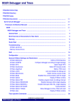
If you need to debug with more than one TRACE32 POWER device, you can address these by using their
device name in the USB configuration. In the TRACE32/PowerView GUI (abbreviated ‘TRACE32’ in this
manual), you can set the device name in a dialog box that you open via the Misc menu > Interface Config
(or via the TRACE32 command line using the IFCONFIG.state command).
Once you have set a device name, the option NODE=<device name> in config.t32 tells TRACE32 to
connect with the specific ‘named USB device’ that you want.
HOST
(PC)
POWER DEBUG / USB3
my-dev-001
.....
HUB
POWER TRACE
my-dev-002
©1989-2014 Lauterbach GmbH
TRACE32 Installation Guide
8
TRACE32-ICD (In-Circuit Debugging)
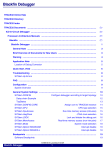
Ethernet Interface (TRACE32-NET)
Ethernet is the physical standard for all connections to workstations or network-based PC configurations.
The protocols UDP, ICMP (for ping), ARP, RARP and DHCP are supported by the TRACE32 device.
The Internet address of the device can be configured manually (e.g. using the USB Interface), with an RARP
or DHCP server, or by using the arp -s command before making the first connection. It is not necessary to
enter router information or a subnet mask.
The TRACE32 device contains a DHCP client to obtain its IP address from a DHCP server (your DHCP
admin usually needs to configure this relation).
In TRACE32, you can set the device name in a dialog box that opens via the Misc menu > Interface Config
(or via the TRACE32 command line using the IFCONFIG.state command). When your DHCP admin sets
up a relationship for this name and a suitable IP address for your network, the DHCP server forwards this
name-to-address information to the DNS server. With the DNS server ‘knowing’ the device name and IP
address, TRACE32 can later use NODE=<device name> in config.t32 to connect with the device.
Alternatively you can also use the IFCONFIG.state dialog to set the IP address manually. Then
NODE=<address> points TRACE32 to your device.
TRACE32 device
HOST
Twisted Pair Connector
HOST
Controller-based Interfaces
With the shift from in-circuit emulation to boundary-scan (JTAG) based debugging, controller-based
interfaces have become much less common. Therefore, controller-based interfaces are not discussed here.
©1989-2014 Lauterbach GmbH
TRACE32 Installation Guide
9
TRACE32-ICD (In-Circuit Debugging)
Minimal Manual Setup
This chapter describes a minimal manual setup of TRACE32 software and hardware for the most
widespread combinations of devices and operating systems.
Even if you do not plan to implement a minimal manual setup, this little tour behind the scenes of TRACE32
helps you gain a better understanding of how to tailor the debug system to your needs.
No one likes a black-box environments - so let’s switch on the light!
Use cases where a minimal manual setup makes sense:
•
Help Lauterbach Support reproduce and solve any debug issue by quickly providing them with
copies of your source and debug files, scripts and TRACE32 files in a minimal software setup
(a.k.a. test-tube installation). Help us help you!
•
Bundle your demo scripts and other files with a minimal TRACE32 software setup to form a selfcontained demonstration kit for use at a trade fair or in a training session.
•
Make portable on a USB stick - always a nice-to-have.
•
In a space-restricted environment, e.g. a small Virtual Machine image.
For a complete installation:
•
For Windows, a TRACE32 DVD installer is available.
See “MS Windows” in ICD Quick Installation, page 16 (icd_quick_installation.pdf).
•
For Linux, see “PC_LINUX” in ICD Quick Installation, page 19 (icd_quick_installation.pdf).
NOTE:
For a regular installation, always use the TRACE32 DVD installer.
Currently there is only a TRACE32 DVD installer for Windows, but newer
versions of this can also generate a file tree for Linux systems.
©1989-2014 Lauterbach GmbH
TRACE32 Installation Guide
10
Minimal Manual Setup
Prerequisites and Recommendations for the Minimal Manual Setup
Windows
The minimal manual setup for Windows requires:
•
Access to an administrator account for driver installation
•
Permission to create folders and files
•
Permission to execute files from these locations
Linux
The minimal manual setup for Linux requires:
•
Administrator rights
•
Firm knowledge of Linux commands to create folders, copy files, set permissions, etc.
Starting November 2012, the TRACE32 PowerView GUI for Linux is available in two variants:
•
Qt GUI
If you choose to install a Linux Qt variant of TRACE32 (e.g. t32marm-qt), then you can skip the font
installation.
•
Motif GUI
TRACE32 for Linux uses Motif libraries for the GUI. These require installation of the TRACE32 fonts.
For information about the font installation, see “Motif GUI specific steps” in ICD Quick Installation,
page 21 (icd_quick_installation.pdf).
Non-TRACE32 Hardware
•
USB cable (even if you want to ultimately use an Ethernet configuration, for easy device setup
you will temporarily want to have a USB cable)
•
If you want to set up an Ethernet configuration, you will need either:
-
an Ethernet cross-over cable, or
-
an Ethernet hub or switch and two patch cables
©1989-2014 Lauterbach GmbH
TRACE32 Installation Guide
11
Minimal Manual Setup
Copy the Required Files (USB and Ethernet)
The following step-by-step description is for a minimal manual setup of TRACE32 (32-bit version) on
Windows and Linux. The file set copied from the TRACE32 installation DVD to a local folder structure is the
minimal ARM debugging file set required for debugging PandaBoard.
The minimal debugging file set is identical for USB and Ethernet, only the content of the configuration file
config.t32 differs.
To copy the required files to their destination folders:
1.
Create this folder structure:
Windows user
Linux user
C:\
/opt/
T32MINI
t32mini
bin
bin
pc_linux
windows
2.
3.
From the TRACE32 installation DVD, copy these files into the T32MINI folder.
File
DVD Location
Description
fcc.t32
...\files
low-level TRACE32 device communication
software
fccarm*.t32
...\files
running on the TRACE32 device, debug support
for one or more cores
help.t32
...\files
index, full text search database, error/warning
messages, and tooltips
t32.men
...\files
top-level English menu file, which also initializes
additional toolbar buttons.
t32font.fon
...\files
TRACE32 system font (Windows only)
Copy these files to the windows or pc_linux folder.
File
DVD Location
Description
t32marm.exe
...\files\bin\windows
TRACE32 for Windows
(TRACE32/PowerView GUI, 32-bit version)
t32marm-qt
...\files\bin\pc_linux
TRACE32 for Linux (32-bit version)
•
A file name suffix -qt marks the Qt GUI
variant of the TRACE32/PowerView GUI.
•
The Motif GUI variant has no such suffix.
Reason for placing the binary into this bin\<os> structure: it resembles the file structure in our update
archives. Then, when updating your minimal installation, you just need to unzip one file.
©1989-2014 Lauterbach GmbH
TRACE32 Installation Guide
12
Minimal Manual Setup
USB Configuration
The USB label is printed on USB-capable TRACE32 devices.
USB
USB
Typical devices include:
•
POWER DEBUG INTERFACE / USB3
POWER DEBUG INTERFACE / USB2
POWER DEBUG INTERFACE / USB
•
µTRACE
•
POWER DEBUG II
•
POWER TRACE / ETHERNET
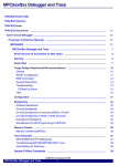
Set Up the Hardware (USB)
1.
Connect the target-specific DEBUG CABLE to the POWER DEBUG INTERFACE / USB3.
2.
Plug a USB cable into the POWER DEBUG INTERFACE / USB3 and the other end into a free
USB port on your Windows / Linux PC (or Workstation).
3.
Connect the power adaptor that came with your POWER device to mains and to the device.
PC
Target
Debug Cable
USB
Cable
PODBUS IN
POWER DEBUG INTERFACE / USB 3
POWER
DEBUG CABLE
USB
POWER
7-9 V
LAUTERBACH
SELECT
EMULATE
DEBUG CABLE
TRIG
PODBUS OUT
JTAG
Connector
LAUTERBACH
POWER DEBUG INTERFACE / USB 3
AC/DC Adapter
©1989-2014 Lauterbach GmbH
TRACE32 Installation Guide
13
Minimal Manual Setup
Install Drivers (USB)
Windows (USB)
Prerequisite for Windows is the installation of the “TRACE32 PODBUS USB driver for Windows”.
1.
On the TRACE32 installation DVD, please navigate to this file:
2.
File
DVD Location
Description
dpinstselect.exe
...\files\bin\windows\driver
USB driver installer
To install, double-click dpinstselect.exe, and then follow the instructions of the installer.
Linux (USB)
For Linux, you don’t need to install any drivers, but you need to make sure that the USB devices have the
proper name and access rights. The access rights and name are usually configured by udev. Please see
the installation directory on the Lauterbach TRACE32 DVD for notes and a sample udev rules file.
File
DVD Location
Description
readme.txt
.../files/bin/pc_linux/udev.conf
Instructions on how to configure Linux to
make Lauterbach USB devices available
If you want to set up an Ethernet configuration on Windows or Linux
For Ethernet, you don’t need any drivers, but you need to make the device “visible” via a name or an IP
address. For this, you need to set up a device name and configure your DHCP server.
(a) If you know ARP and can set up DHCP or configure a local hosts file, you can use this knowledge to map
the MAC address of the TRACE32 POWER device (printed on the device) to an IP address and/or host
name and then use this as the NODE= part of the configuration file.
(b) An easier way for the device configuration (to set up a device name or IP address in a TRACE32 device)
is to use USB:
•
For Windows + Ethernet, please install the USB driver. See “Windows (USB)”, page 14.
•
For Linux + Ethernet, please configure your udev system. See “Linux (USB)”, page 14.
©1989-2014 Lauterbach GmbH
TRACE32 Installation Guide
14
Minimal Manual Setup
Create the Configuration File (USB and NET)
1.
In the windows or pc_linux folder where you have placed the TRACE32 executable, right-click
and create a file named config.t32.
2.
Open the config.t32 file with an ASCII editor.
3.
Copy and paste one of the example configurations into the config.t32 file:
-
For Windows, use this example.
-
For Linux, use this example.
4.
Edit your config.t32 file - i.e. use your own paths - and assign the ID you want (see ID=).
5.
Save your config.t32 file and close it.
-
If you want a USB configuration, please continue at “Identify the Peripheral File”, page 20.
-
If you want an Ethernet configuration, please continue at “Ethernet Configuration”, page 16.
Windows:
// TRACE32 configuration file for USB (Windows)
OS=
ID=T32TEST001
TMP=C:\temp
; temporary directory for TRACE32
SYS=C:\T32MINI
; system directory for TRACE32
HELP=G:\SERIAL\CD\files\pdf
; help directory for TRACE32
PBI=
USB
PRINTER=WINDOWS
Linux:
// TRACE32 configuration file for USB (Linux)
OS=
ID=T32TEST001
TMP=/var/tmp
; temporary directory for TRACE32
SYS=/opt/t32mini
; system directory for TRACE32
HELP=/media/TRACE32/files/pdf
; help directory for TRACE32
PBI=
USB
©1989-2014 Lauterbach GmbH
TRACE32 Installation Guide
15
Minimal Manual Setup
Ethernet Configuration
NOTE:
The easiest way to set the device name for an Ethernet configuration is to start
with a USB connection.
So, please continue at “Copy the Required Files (USB and Ethernet)”, page
12.
Then complete the rest of this chapter.
The ETHERNET label is printed on Ethernet-capable TRACE32 devices.
Ethernet
Typical devices include:
•
POWER DEBUG II
•
POWER TRACE / ETHERNET
Changing an existing TRACE32 USB configuration to a TRACE32 Ethernet configuration involves these
main steps:
•
Assign a hostname to the TRACE32 device.
•
Modify the configuration file to change the connection from USB to Ethernet.
•
Power-off the TRACE32 device
•
Disconnect USB from the TRACE32 device
•
Connect the TRACE32 device via an Ethernet cable
•
Power-on the TRACE32 device.
These steps are explained step by step in the sections below.
©1989-2014 Lauterbach GmbH
TRACE32 Installation Guide
16
Minimal Manual Setup
Assign a Hostname to the TRACE32 Device (Ethernet)
1.
Make sure your TRACE32 device is connected via USB to your PC or Unix workstation, and you
have a configuration file that is properly set up for USB.
2.
Power-on the TRACE32 hardware.
3.
Start the TRACE32 GUI by double-clicking the TRACE32 executable in the windows or pc_linux
folder.
4.
From the Misc menu, select Interface Config to open the IFCONFIG window.
5.
In the entry field below device name, type the hostname you want to assign to the TRACE32
device.
6.
Do one of the following:
7.
-
If you want to use an Ethernet hub or switch, select the DHCP (via device name) checkbox.
-
If you to use a cross-over cable, clear the DHCP (via device name) checkbox, and enter the IP
address you want to use for this TRACE32 device in the ip address box.
Select the full duplex checkbox.
Currently it is still a USB configuration.
8.
Click Save to device.
This saves the device name in the internal memory of the TRACE32 device.
9.
Click Close.
10.
Choose File menu > exit to close the TRACE32 PowerView GUI.
©1989-2014 Lauterbach GmbH
TRACE32 Installation Guide
17
Minimal Manual Setup
Modify the Configuration File (Ethernet)
Most sites will use Ethernet with DHCP and DNS to assign IP addresses and hostnames to devices.
Contact your system administrator for a hostname, and then proceed as follows:
1.
In the windows or pc_linux folder where you have placed the TRACE32 executable, open the
config.t32 file with an ASCII editor.
2.
Modify the config.t32 file:
-
For Windows, refer to this this example.
-
For Linux, refer to this example.
NOTE:
Do NOT use whitespaces around the operator = in the configuration files.
3.
For NODE= enter the hostname you have received from your system administrator.
4.
Save your config.t32 file and close it.
Example configuration for Windows:
// TRACE32 configuration file for NET
// (Windows)
OS=
ID=T32TEST002
TMP=C:\temp
; temporary directory for TRACE32
SYS=C:\T32MINI
; system directory for TRACE32
HELP=N:\TRACE32DVD\files\pdf
; help directory for TRACE32
PBI=
NET
NODE=pod-hen01
; i.e. EtherNET
; hostname assigned to the TRACE32 device
PRINTER=WINDOWS
Example configuration for Linux:
// TRACE32 configuration file for NET
// (Linux/MacOSX/Solaris)
OS=
ID=T32TEST002
TMP=/var/tmp
SYS=/opt/t32mini
HELP=/media/TRACE32/files/pdf
PBI=
NET
NODE=pod-hen01
; i.e. EtherNET
; hostname assigned to the TRACE32 device
©1989-2014 Lauterbach GmbH
TRACE32 Installation Guide
18
Minimal Manual Setup
Re-configure the Hardware (Ethernet)
Remember that we started with a USB configuration, and then modified the TRACE32 configuration file for
Ethernet. Now we are ready to re-configure the TRACE32 hardware for Ethernet as well.
A direct cross-over cable link between TRACE32 device and PC or Unix workstation can only be used if you
have assigned an IP address to the TRACE32 device as described in “Assign a Hostname to the
TRACE32 Device (Ethernet)”, page 17. Otherwise you need a hub (or switch) and patch cable(s).
To re-configure the hardware for Ethernet:
1.
Unplug the USB cable.
2.
Do one of the following:
-
Plug an Ethernet cable into the POWER TOOL / ETHERNET and the other end into a free
port on an Ethernet hub or switch.
-
If you want a direct connection with your Windows / Linux PC (or Workstation), plug the
Ethernet cross-over cable directly into the POWER TOOL and your PC.
HUB
PC or
Workstation
1 GBit Ethernet
Target
PODBUS SYNC
Debug Cable
POWER DEBUG II
POWER
TRIG
ACTIVITY
ETHERNET
POWER
7-9 V
PODBUS OUT
LAUTERBACH
DEBUG CABLE
DEBUG CABLE
LINK
LAUTERBACH
RUNNING
USB
Ethernet
Cable
JTAG
Connector
SELECT
PODBUS EXPRESS OUT
POWER DEBUG II
AC/DC Adapter
NOTE:
Now continue with “Identify the Peripheral File”, page 20.
©1989-2014 Lauterbach GmbH
TRACE32 Installation Guide
19
Minimal Manual Setup
Identify the Peripheral File
This step-by-step procedure describes how to identify the missing peripheral file (*.per) for a minimal manual
setup. A full installation setup copies all available *.per files to the system directory, by default C:\t32.
To identify the missing *.per file in a minimal manual setup:
1.
If they are not powered-on already, switch on the TRACE32 hardware, and then power-on your
target board.
2.
Start TRACE32 by double-clicking the TRACE32 executable in the windows or pc_linux folder.
3.
At the TRACE32 command line, type these commands:
SYStem.CPU ;Opens the SYStem.CPU window, displaying a list of CPUs.
;Double-click the CPU you want to use, e.g. OMAP4430.
PER.view
;Opens the peripheral file for the selected CPU.
;If the file is not found, its name is displayed
;in the message bar, see screenshots below.
AREA.view
;Allows you to copy the file name of the missing file.
Remember that we have not copied any peripheral file (*.per) yet. As a result, TRACE32 displays an
error message.
4.
From the TRACE32 installation DVD, copy the *.per file to the system directory; in our example,
copy peromap4430app.per to the T32MINI folder.
File
DVD Location
Description
per*.per
...\files
Definitions for on-chip peripherals (text files)
You do NOT need to re-start TRACE32.
5.
To display the PER file contents, type these commands:
SYStem.Up
PER.view ;Displays the peripheral file for the selected CPU,
;in our example, for OMAP4430.
©1989-2014 Lauterbach GmbH
TRACE32 Installation Guide
20
Minimal Manual Setup
This completes the minimal manual setup of TRACE32. For the curious reader and user:
The screenshot below is an example of the IFCONFIG.state window after we have changed the USB
configuration into an ETHERNET configuration, as described in this chapter about the minimal manual
setup:
Gigabit Ethernet - BASE T
©1989-2014 Lauterbach GmbH
TRACE32 Installation Guide
21
Minimal Manual Setup
TRACE32-ICE (In-Circuit Emulation)
Legacy Host Interfaces
These interfaces have become obsolete or are no longer for sale.
Parallel Interface (TRACE32-PAR)
The PODBUS PARALLEL INTERFACE (host-based) was the former standard host interface for PC. With
the widespread availability of faster peripheral connection methods like USB and Ethernet it has become
obsolete.
PC
LPT1:
PAR
T32
Superseded by Ethernet and USB.
Serial Interface (TRACE32-SER)
This interface is mainly used on non-standard hosts. The physical link may be RS232 or RS422. The
maximum speed is 1 MBit/s with asynchronous transfer modes.
HOST
T32
GND
No longer available.
Fiber Optic (TRACE32-SER, TRACE32-NET)
This interface is used on PCs only. A special interface card is needed (AT or MC bus). The max. speed is
2 MBit/s (ETHERNET card) or 1 MBit/s (SER).
HOST
T32
Fiber Optic
No longer available.
©1989-2014 Lauterbach GmbH
TRACE32 Installation Guide
22
TRACE32-ICE (In-Circuit Emulation)
SCSI Interface (TRACE32-SER, TRACE32-NET)
This interface is made by a special interface box, which connects the SCSI bus to the fiber optic interface.
The interface supports all workstations (UNIX or VMS).
HOST
SCSI
SCSI
SASO box
T32
Fiber Optic
No longer available.
Host Interface Cards
Both interface cards are no longer available.
Fiber Optic Interface (PC-ISA)
This interface card occupies a short slot with an 8 bit bus connector. The address selector is set to 360H,
interrupts and DMA are not used in the standard mode. No default settings must be changed on software
installation. If a DMA based driver is used, the DMA switches will be set to ON (for faster download).
Default switch settings on the interface card:
address
ON
OFF
interrupt
A2 A3 A4 A5 A6 A7 A8 A9
switch open:
1
switch closed: 0
dma
I7 I5 I4 I3 D1 D1 D3 D3
switch open: IRQ/DMA not used
switch closed: IRQ/DMA used
©1989-2014 Lauterbach GmbH
TRACE32 Installation Guide
23
TRACE32-ICE (In-Circuit Emulation)
Fiber Optic Interface (PC-MCA)
This card contains no DIP switches or selectors. The interface address is configured by the adapter
configuration file. The address of the port must also be selected there.
To install the adapter in your Micro Channel computer, you have to complete the following steps:
1.
Copy the file '@50DF.ADF' to the reference disk (you got this disk with your MicroChannelComputer).
2.
Turn off your computer and install the adapter in any available slot.
3.
Insert the reference disk in floppy drive A:.
4.
Turn on the system.
5.
After booting the setup-program will ask you whether to do an auto- configuration or not. Answer
this question with 'No'.
6.
Choose the 'configuration' option in the main menu of the setup program.
7.
Choose the 'auto configuration' option in the configuration menu.
8.
If the auto-configuration fails, you must change the 'ADF' file. Call technical support for details.
9.
If the configuration was successful, choose the option 'show configuration' and scroll through the
slot-list until you see the entry for the TRACE32 Fiber Optic Interface and its Base I/O-Address.
Record this base address.
10.
If the base address is not 360H, change the line 'ADDRESS=' in the configuration file 'config.t32'
to the correct address. NOTE: The address must be entered in decimal.
©1989-2014 Lauterbach GmbH
TRACE32 Installation Guide
24
TRACE32-ICE (In-Circuit Emulation)
Hardware Installation (TRACE32-ICE)
Remove Modules
Switch power off before opening the system. Remove the sliders between the module and other attached
modules. Begin to apply force from the back end of the system, near the hole for the fan, and disconnect the
module slowly.
Add Modules
Switch power off before opening the system. Check the connectors of the module to ensure proper
alignment of the pins. Fit the connectors between the new module and the system. Be sure not to bend a pin
when connecting the modules. Apply force to the connectors of the new module, beginning from the front of
the system. If the module is snapped in, once apply force to all connectors to ensure proper contact. As the
last step attach the cover plate and the sliders to the module.
Apply force to the connectors
©1989-2014 Lauterbach GmbH
TRACE32 Installation Guide
25
Hardware Installation (TRACE32-ICE)
System Memory (SCU/PODETH)
The system controller (SCU) or the PODBUS Ethernet interface (PODETH) consists of main processor,
memory and the host interface. The main software and the user interface is running on this processor.
Symbol information is also held in the SCU/PODETH memory. If the error message 'out of memory' is
displayed during the download of a large program, it may be necessary to upgrade the memory.
•
The max. size of memory is 8 MBytes for the SCU16 and 16 MBytes for the SCU32 and up to 64
MByte for the current SCU type.
•
The max. size of memory for the PODETH interface is 128 MByte.
The currently used memory size can be displayed with the command SETUP.MEMory. As a worst case
calculation for the required memory size for an HLL debug object file the following formula can be used:
MEMORY_SIZE = ( FILE_SIZE - BINARY_CODE_SIZE ) * 3
For a memory upgrade the memory module in the SCU/PODETH must be exchanged.
For SCU16, SCU-PAR, SCU32/15 and SCU32/22 memory extensions can be inserted in the SCU module
after removing the cover plate with the fan.
SCU16-MX2
..
..
1
2 MByte
1
..
..
1
4 MByte
1
..
..
1
6 MByte
1
..
..
8 MByte
SCU32-MX4
:: ::::
:: ::::
:: ::::
:: ::::
:: ::::
4 MByte
::::
::
::::
::
::::
::
::::
::
::::
::
8 MByte 12 MByte
16 MByte
Standard 1MBit*4 (60/80ns) ZIP memory chips can be used to upgrade the memory. Eight memories must
be used for a 4 MByte extension. Memory must be plugged in according to the schematics above, e.g. for 12
MByte the three memories in position 4, 8 and 12 must be plugged in.
©1989-2014 Lauterbach GmbH
TRACE32 Installation Guide
26
Hardware Installation (TRACE32-ICE)
LEDs on TRACE32 Hardware Modules
PowerTools
Within the PowerTools family we distinguish three types of hardware modules:
1.
Hardware modules with host interface which must be connected to the host (PODBUS
SYNCH):
POWER DEBUG INTERFACE / USB 3
POWER DEBUG II
2.
Hardware modules with host interface which may be connected to the host (PODBUS IN):
POWER DEBUG INTERFACE / USB 2
POWER DEBUG / ETHERNET
POWER TRACE / ETHERNET
3.
Hardware modules without host interface
POWER TRACE II
POWER PROBE / LOGIC ANALYZER
POWER INTEGRATOR
POWER INTEGRATOR II
4.
Stand-alone hardware module with host interface
µTrace
POWER LED
If the POWER LED is on, this indicates that a power supply is connected. This applies to all hardware
modules except POWER TRACE II and POWER INTEGRATOR II.
©1989-2014 Lauterbach GmbH
TRACE32 Installation Guide
27
LEDs on TRACE32 Hardware Modules
POWER TRACE II/POWER INTEGRATOR II
POWER TRACE II/POWER INTEGRATOR II are only partially powered when a power supply is connected
but the TRACE32 software is not started. This avoid unnecessary noise. The POWER LED is flashing to
indicate this partly powered state.
POWER TRACE II/POWER INTEGRATOR II are completely powered when the TRACE32 software is
started.
HUB
PC or
Workstation
1 GBit Ethernet
Target
Debug Cable
PODBUS SYNC
POWER DEBUG II
POWER
TRIG
JTAG
Connector
SELECT
ACTIVITY
ETHERNET
POWER
7-9 V
PODBUS OUT
PODBUS IN
LAUTERBACH
POWER TRACE II
DEBUG CABLE
DEBUG CABLE
LINK
LAUTERBACH
RUNNING
USB
Ethernet
Cable
PODBUS EXPRESS OUT
PODBUS EXPRESS IN
LAUTERBACH
POWER
RECORD
RUNNING
LOGIC ANALYZER PROBE
POWER
7-9V
PREPROCESSOR / NEXUS
SELECT
B
A
Trace
Connector
C
PODBUS OUT
PODBUS EXPRESS OUT
POWER DEBUG II
POWER TRACE II
Preprocessor
AC/DC Adapter
In the standard configuration (one POWER TRACE II/POWER INTEGRATOR II is assembled with a
POWER DEBUG II module) the power supply connected to POWER DEBUG II is sufficient to supply both
units. Any further module needs an extra power supply (more the 7 A).
A POWER LED that is still flashing after the TRACE32 software is started indicates that the current power
supply is not sufficient. POWER TRACE II/POWER INTEGRATOR II provide their own POWER 7-9 V
connector. This connector can be used to connect an additional power supply.
©1989-2014 Lauterbach GmbH
TRACE32 Installation Guide
28
LEDs on TRACE32 Hardware Modules
SELECT LED
TRACE32 Software not Started
The following applies only to the hardware module that is connected to the host:
The SELECT LED flashes regularly when the self-test of the hardware module was successfully completed.
If the self test failed, the following error codes are flashed:
•
Three flashes, then a pause: memory test failed
•
Six flashes, then a pause: buffer overflow
•
Nine flashes, then a pause: failed to load firmware
•
Twelve flashes, then a pause: checksum error.
In any case, please contact your local Lauterbach support.
NOTE:
The uTrace does not have a SELECT LED, because it is a stand-alone
hardware module. The POWER LED is used here to indicate that a self-test
failed.
TRACE32 Software Started
The SELECT LED is on when the TRACE32 software in communication with the hardware module.
©1989-2014 Lauterbach GmbH
TRACE32 Installation Guide
29
LEDs on TRACE32 Hardware Modules
RUNNING/EMULATE LED
+
NOTE:
The state of this LED has no meaning as long as the TRACE32 software is not
started.
The following applies to all hardware modules except POWER TRACE II and POWER INTEGRATOR II:
•
If a single-core processor is debugged, the RUNNING/EMULATE LED is ON, when the program
execution is running. The RUNNING/EMULATE LED corresponds with running indicated in the
Debug field of the TRACE32 PowerView state line.
•
If a multi-core chip is debugged, the RUNNING/EMULATE LED is ON, when the program
execution is running on the core that is the master of the debug communication
(SYStem.CONFIG Slave OFF).
The following applied for POWER TRACE II:
•
If the on-chip trace generation logic generates Nexus 5001™ compliant trace messages the
RUNNING is ON, when the program execution is running. This is realizable because the trace
generation logic generates Debug Status Messages at the start and the stop of the program
execution.
•
For all other trace protocols the RUNNING LED is on, if the POWER TRACE II hardware is ready
to record trace information (see also RECORD LED description) and valid trace information is
received.
The following applied for POWER INTEGRATOR II:
•
For all other trace protocols the RUNNING LED is on, if the POWER TRACE II hardware is ready
to record trace information (see also RECORD LED description) and valid trace information is
received.
RECORD/RECORDING/TRACE LED
NOTE:
The state of this LED has no meaning as long as the TRACE32 software is not
started.
The RECORD LED is on when the logic analyzer/ trace recording is armed. Armed means incoming trace
data are recorded. The RECORD LED corresponds with ARM indicated in the Trace field of the
TRACE32 PowerView state line.
©1989-2014 Lauterbach GmbH
TRACE32 Installation Guide
30
LEDs on TRACE32 Hardware Modules
TRIGGER LED
NOTE:
The state of this LED has no meaning as long as the TRACE32 software is not
started.
The TRIGGER LED is on when the logic analyzer encountered a trigger event. The TRIGGER LED
corresponds with TRIGger indicated in the Trace field of the TRACE32 PowerView state line.
ERROR LED
The ERROR LED on the POWER INTEGRATOR has no function.
©1989-2014 Lauterbach GmbH
TRACE32 Installation Guide
31
LEDs on TRACE32 Hardware Modules
Ethernet LEDs
LEDs on POWER DEBUG II
LINK
Physical link established.
ACTIVITY
Ethernet packets received respectively sent.
LEDs on POWER DEBUG / ETHERNET and POWER TRACE / ETHERNET
CONNECT ERROR
Ethernet connection error occurred.
TRANSMIT
Ethernet packets sent.
RECEIVE
Ethernet packets received.
COLLISION
Ethernet collision occurred.
©1989-2014 Lauterbach GmbH
TRACE32 Installation Guide
32
LEDs on TRACE32 Hardware Modules
SCU32
Rear panel (Fibre optic connector/AUI connector):
Fibre optic
connector
Error
LED
AUI
connector
Rear panel (Parallel interface):
Error
LED
Parallel
connector
When the TRACE32 system is starting up, the Error LED on the rear of the System Control Unit (SCU) lights
for 5 … 40 s, depending on the memory size. After this delay time the error codes shown below may be
blinked:
on
off
0.1 sec.
0.1 sec.
No carrier (fiber optic interface only)
1.0 sec.
0.2 sec.
on
off
Waiting for connection (ETHERNET only)
0.5 to 5.0 sec.
0.2 sec.
on
off
Time-out of peripheral systems
0.5 to 5.0 sec.
0.4 sec.
on
off
Fatal error
long sync.
on
off
1.0 sec.
bit 7
bit 0
parity
long pause
...
0.1 sec. is '0', 0.5 sec. is '1'
Selftest error with error code
©1989-2014 Lauterbach GmbH
TRACE32 Installation Guide
33
LEDs on TRACE32 Hardware Modules
SCU32-MPC
Rear panel:
SYNC
Connector
USB
Interface
LPT
Interface
Twisted Pair
Interface
AUI
Connector
Ethernet
LEDs
Ethernet LEDs
T
Transmit activity.
R
Receive activity.
C
Collision activity.
L
Twisted pair link integrity.
S
Twisted Pair Polarity Error (receiver inputs TPRX+, TPRX- are reversed).
X
Twisted Pair Jabber condition detected.
E
In error case an error code is pulsed.
A
On if device is active, flashes if device is not used.
©1989-2014 Lauterbach GmbH
TRACE32 Installation Guide
34
LEDs on TRACE32 Hardware Modules
SCU32-MPC 100MBit
Rear panel:
SYNC
Connector
LPT
Interface
USB
Interface
Twisted Pair
Interface
Ethernet
LEDs
Ethernet LEDs
T
Transmit activity.
R
Receive activity.
C
Collision activity.
L
Twisted pair link integrity.
S
Speed, on if 100MBit Ethernet is used, off if 10MBit Ethernet is used.
F
Full duplex.
E
In error case an error code is pulsed.
A
On if device is active, flashes if device is not used.
©1989-2014 Lauterbach GmbH
TRACE32 Installation Guide
35
LEDs on TRACE32 Hardware Modules
PODBUS Ethernet Controller
LEDs
POWER
External power is supplied.
ACTIVE
On if device is active, flashes if device is not used.
ERROR
In error case an error code is pulsed.
TRANSMIT
Transmit activity.
RECEIVE
Receive activity.
COLLISION
Collision activity.
LINK
Twisted pair link integrity.
POLARITY
Twisted Pair Polarity Error (receiver inputs TPRX+, TPRX- are reversed).
JABBER
Twisted Pair Jabber condition detected.
©1989-2014 Lauterbach GmbH
TRACE32 Installation Guide
36
LEDs on TRACE32 Hardware Modules
PODBUS Ethernet Controller/100
LEDs
POWER
External power is supplied.
ACTIVE
On if device is active, flashes if device is not used.
ERROR
In error case an error code is pulsed.
TRANSMIT
Transmit activity.
RECEIVE
Receive activity.
COLLISION
Collision activity.
LINK
Twisted pair link integrity.
100 MBPS
On if 100 MBit Ethernet is used, off if 10MBit Ethernet is used.
AUX
Full duplex.
©1989-2014 Lauterbach GmbH
TRACE32 Installation Guide
37
LEDs on TRACE32 Hardware Modules
TRACE32-Interfaces
TRACE32-USB
Connector (USB 3.x)
Pin
Signal Name
Color
1
VCC
red
2
D-
white
3
D+
green
4
GND
black
5
StdB_SSTX-
blue
6
StdB_SSTX+
yellow
7
GND_DRAIN
shield
8
StdB_SSRX-
purple
9
StdB_SSRX+
orange
Connector (USB 2.0 and 1.x)
Pin
Signal Name
Color
1
VCC
red
2
D-
white
3
D+
green
4
GND
black
USB Interfaces (USB 3.x to 1.x)
TRACE32 Power Tools can be connected with standard USB cables to any free USB port on the PC itself or
on a connected USB hub (stand-alone or embedded in a peripheral, e.g. a monitor or keyboard).
From the tables above you see that a USB connector can also provide power to a device. But the 2.5 Watts
provided with USB 2.0, and the 4.5 Watts specified for USB 3.0 are not enough for the sophisticated hispeed debugging hardware used in our TRACE32 tools. Therefore TRACE32 devices are “self-powered”,
i.e. they get their power from an external power supply (that usually comes with the device).
©1989-2014 Lauterbach GmbH
TRACE32 Installation Guide
38
TRACE32-Interfaces
USB 3.x
POWER DEBUG INTERFACE / USB3 and µTrace are the first Lauterbach TRACE32 Power Tools that
support USB 3.0 SuperSpeed (max. bus transfer rate of 5 GBit/s). To take advantage of this high speed,
please make sure you operate these TRACE32 devices on USB3 ports, and with matching USB3 cables.
The net transfer speed that can be obtained under real working conditions depends on a number of factors
(including PC CPU and USB port chip, cable quality, but also the speed of the target JTAG interface or
TRACE port) and has been observed to be roughly between 40 MBytes/s and 100 MBytes/s.
If you don’t have any free USB 3.x port, you can also use an USB 2.0 port and USB 2.0 cable. Some loss of
transfer speed is expected, but because of the improved internal data path layout introduced for USB 3.x, the
devices still have higher transfer rates via USB 2.0 (between 20 and 35 MBytes/s) than our “pure USB 2.0”
devices.
The USB 3.x standard does not specify any maximum cable length, but for SuperSpeed connections we
recommend using 3 metres or less of high-quality cable, and to plug it directly into a PC USB3 port.
For comparison, a microwave oven uses 2.45 GHz frequencies, USB 3.0 uses 5.0 GHz. This means that
interference from other devices, within your PC and from external devices, might affect USB transfers.
USB 2.0
POWER DEBUG INTERFACE / USB2, POWER DEBUG II and POWER DEBUG / ETHERNET all
implement a combined USB 2.0 and USB 1.x interface. Connected to a USB 2.0 port, they run in Hi-Speed
mode (480 MBit/s) with observed transfer rates of up to 12 MBytes/s.
Please note that the USB specification limits USB 2.0 cable length to 5 metres. This already includes any
device-internal wiring, however, so e.g. a laptop plugged into a docking station might cause trouble when
you use a 5 metre long USB cable. Also please note that 480 MBit/s means that the USB 2.0 bus has to
handle 480 MHz frequencies. At these speeds, electromagnetic interference already becomes an issue.
USB 1.x
The POWER DEBUG INTERFACE / USB (as one example of this device category) is a full-speed device
which uses the full USB 1.x bandwidth of 12 Mbps. USB 2.0 devices connected to a USB1.x port, will have
transfer rates of up to 1.5 MBytes/s (some data can be additionally compressed, so in some cases you
might observe slightly higher transfer rates).
Low-speed USB 1.x with 1.5 MHz transfer rate is not supported by TRACE32 devices.
©1989-2014 Lauterbach GmbH
TRACE32 Installation Guide
39
TRACE32-Interfaces
TRACE32-ETHERNET
Standard connector for the ethernet connection on TRACE32 development tools is a twisted pair connector.
8P8C-Connector (T568A/B, ‘RJ45’)
This is the standard connector for Ethernet interfaces, for use with twisted-pair cabling.
1000BT
100BT
1
2
3
4
5
6
7
8
1
2
3
4
5
6
7
8
TRP1+
TRP1TRP2+
TRP3+
TRP3TRP2TRP4+
TRP4-
Termination (term):
75 Ohms to GND
TRP1+
TRP1TRP2+
(termA)
(termA)
TRP2(termB)
(termB)
AUI-Connector
This is a legacy interface that is not available on newer TRACE32 devices.
1
1
2
3
4
5
6
7
8
9
2
10
3
11
4
12
5
13
GND
COL+
OUT+
GND
IN+
GND
N/C
N/C
6
14
7
15
8
9
10
11
12
13
14
15
COLOUTGND
IN+12V (0.25 A max)
GND
GND
Ethernet Interface
The MAC address of the Ethernet interface is recorded on the bottom of the system. The physical transfer
speed is 10 MBit/s (legacy devices), 100 MBit/s or 1000 MBit/s. In idle mode, ETHERNET traffic is reduced
to a minimum of 2 packets/s.
The command SETUP.URATE can limit the update speed of the window system, and thus reduce the
Ethernet traffic, too. The command IFCONFIG.PROfile shows statistics about Ethernet usage.
©1989-2014 Lauterbach GmbH
TRACE32 Installation Guide
40
TRACE32-Interfaces
Selection of Transfer Protocol
Transfer protocol and interface are selected automatically. The interface, which first establishes a connection
is selected for operation. The baud rate and protocol of the fiber optic interface is selected automatically, too.
The fiber optic cable can be left connected if the Ethernet interface will be used.
©1989-2014 Lauterbach GmbH
TRACE32 Installation Guide
41
TRACE32-Interfaces
TRACE32-PAR
This is a legacy interface that is not available on newer TRACE32 devices.
Connector
1
1
2
3
4
5
6
7
8
9
10
11
12
13
14
2
15
3
16
4
17
5
18
-STR
D0
D1
D2
D3
D4
D5
D6
D7
-ACK
BUSY
PE
SELECT
6
19
7
20
14
15
16
17
18
19
20
21
22
23
24
25
8
21
9
22
10
23
11
24
12
25
13
-AF
-ERROR
-INIT
-SELIN
GND
GND
GND
GND
GND
GND
GND
GND
Parallel Interface
The interface cable is connected directly to the printer port of the PC. TRACE32 supports EPP and ECP
mode. The effective download speed is approximately 350 KByte/s.
©1989-2014 Lauterbach GmbH
TRACE32 Installation Guide
42
TRACE32-Interfaces
TRACE32-SER
This is a legacy interface that is not available on newer TRACE32 devices.
Connector
20 21 22 23 24 25 26 27 28 29 30 31 32 33 34 35 36 37
1 2 3 4 5 6 7 8 9 10 11 12 13 14 15 16 17 18 19
1
2
3
4
5
6
7
8
9
10
11
12
13
14
15
16
17
18
19
GND
TXD RS232-0
RXD RS232-0
RTS RS232-0
CTS RS232-0
TXD RS232-1
RXD RS232-1
RTS RS232-1
CTS RS232-1
+10V
-10V
GND
+5V
GND
RXD+ RS422
RXD- RS422
TXD+ RS422
TXD- RS422
GND
20
21
22
23
24
25
26
27
28
29
30
31
32
33
34
35
36
37
CODE-0
CODE-1
CODE-2
CODE-3
CODE-4
CODE-5
CODE-6
CODE-7
CODE-8
CODE-9
CODE-10
CODE-11
GND
CLKIN+
CLKINCLKOUT+
CLKOUTGND
RS232 Interfaces
Two serial interfaces are implemented. Both interfaces are no longer available.
RS422-Interface
This interface is very flexible. The interface consists of clock input, clock output, data input and data output
lines. The transfer protocol is asynchronous. The clock rate may be up to 1 MHz. Clock input is the same for
receiver and transmitter. Clock signal is either generated by TRACE32 or the host computer.
Fiber Optic Interface
This interface can be used for all PC-compatible host computers. For installation no change on the interface
set-up must be made. The physical transfer speed is 1MBit/s.
©1989-2014 Lauterbach GmbH
TRACE32 Installation Guide
43
TRACE32-Interfaces
Selection of Transfer Protocol
The transfer protocol is selected by coding of the interface cable connector. No change on TRACE32 system
must be made by changing between different host computers.
The transfer protocol is defined by the input lines CODE-0 to CODE-11. A logical 0 is defined by shortening
the input pin to ground, logical 1 is set with an open input line.
If no interface cable is used, the fiber optic link will be selected by default.
Selection of Interface
CODE-11-10-9-8
1111
Fiber Optic asynch. with handshake
1110
Fiber Optic asynch. DMA (boot EPROM version 2.3 or less)
1101
reserved
1100
RS232 no handshake
1011
RS232 software handshake
1010
RS422 no handshake
1001
RS422 software handshake
1000
reserved
….
0000
reserved
©1989-2014 Lauterbach GmbH
TRACE32 Installation Guide
44
TRACE32-Interfaces
Asynchronous RS232/RS422 Driver
CODE-2-1-0
baud rate
111
9600
110
19200
101
38400
100
76800
011
153600
010
307200
001
500000 (RS422 only, boot EPROM 3.x)
000
1MBit (RS422 only, boot EPROM 3.x)
CODE-4-5
(used on software handshake only)
00
mode 0
01
…
10
…
11
mode 3
CODE-4
(no handshake)
0
mode 0
1
mode 1
CODE-6
0
block checksum, 8 bit data, no parity, 1 stop bit
1
parity, 8 bit data, even parity, 1 stop bit
All other pins must be left open. For details in selecting a protocol refer to the software part of the installation
manual.
©1989-2014 Lauterbach GmbH
TRACE32 Installation Guide
45
TRACE32-Interfaces
SASO
This is a legacy interface that is not available on newer TRACE32 devices.
Connector
The SASO box has two 50-pin female high density connectors, following the SCSI-II standard. Cables to
connect to other standards like SCSI-I, D-SUB or DEC are available.
Fiber Optic Interface
The transfer speed is 1, 2 or 4 MBit/s. The direct DMA protocol is used. SCUs with boot EPROM version 2.3
or less must select this protocol by shorting pin 28 and 32 on the 37-pin connector. SCUs with boot EPROM
3.x choose this protocol automatically. The interface system selects the highest transfer rate possible.
Selection of Interface
LED
LED
ON
OFF
2
HC 2MB 1MB
1
0
NODE-ID
HC
High Current Fiber Optic (for 2/4 MBit or long distance)
2MB
Limit transfer speed to max. 2 MBit/s
1MB
Limit transfer speed to 1 MBit/s
NODE-ID
SCSI address (default: 2)
©1989-2014 Lauterbach GmbH
TRACE32 Installation Guide
46
TRACE32-Interfaces
SYSTEM SOFTWARE
Files and Directories
The TRACE32 system needs two fixed directories. On the system directory all programs and data tables are
stored. The temporary directory is used for temporary data tables. On multi-user systems with more than
one TRACE32 device, all system files may be shared. Temporary directories must be kept separate for each
user. Either different temp directories can be used, or the first characters of temporary file names have to be
different for each user. These first characters are defined by the user ID code.
Example of the separation of pathes:
Systemtype
ID code
System dir.
Temporary directory (example)
single user
T32
C:\T32\*.*
C:\TMP\T32?????
multi user option 1
T32
C:\T32\*.*
C:\userid\TMP\T32?????
multi user option 2
userid
C:\T32\*.*
C:\TMP\userid?????
The paths name definition for system and temp directories can be done via environment variables (of the
host operating system) or in the TRACE32 configuration file. The configuration of these path names in the
config.t32 file is only useful when environment variables are hard to define.
Environment variables used by TRACE32:
Environment
config.t32
OS section
usage
T32ID
ID=
ID code for temporary files (prefix)
T32SYS
SYS=
Directory for system files
T32TMP
TMP=
Directory for temporary files
T32HELP
HELP=
Directory for the PDF help files
T32CONFIG
Pathname of configuration file
(used instead of config.t32)
ACROBAT_PATH
Unix only: Installation directory of the Acrobat Reader
(acroread)
©1989-2014 Lauterbach GmbH
TRACE32 Installation Guide
47
SYSTEM SOFTWARE
If defined in the configuration file, the definitions must be made in the "OS=" section:
OS=
ID=ste
SYS=c:\t32
TMP=c:\tmp
HELP=c:\t32\pdf
PBI=
USB
…
©1989-2014 Lauterbach GmbH
TRACE32 Installation Guide
48
SYSTEM SOFTWARE
TRACE32 System Files
t32*(.exe)
TRACE32/PowerView GUI executable, e.g. t32mppc.exe, t32marm.exe, …
config.t32
Default name of configuration file
license.t32
Default name of software license file (only present if required)
boot.t32
boot loader and linker (downloaded to TRACE32 device by the TRACE32 GUI)
boot*.t32
boot files generated by the loader/linker
mcc*.t32
TRACE32 device software for SCU with NSC-CPU
mcp*.t32
TRACE32 device software (SCUPPC, PODBUS ETHERNET CONTROLLER)
fcc*.t32
TRACE32 device software for POWER TOOLS and FIRE
scc*.t32
TRACE32 device software for ICE
per*.per
definition file for on-chip peripherals (text files)
help.t32
*.pdf
trace32.api
Help index, full text search database, tooltip text and error/warning messages
Online manual files (in the subdirectory named as HELP= in the config file)
TRACE32 interface file to Acrobat Reader API
men*.men
additional CPU- or task-specific menu files
t32.men
top-level English menu file
t32jp.men
top-level Japanese menu file
t32jp-utf-8.men
top-level Japanese menu file in UTF-8 format
t32.cmm
start-up file (PRACTICE script)
t32pro.ps
postscript header file (page and formatting pre-amble for postscript output)
t32font.fon
TRACE32 font file (WINDOWS only)
xplib.t32
library for FLASH programmer
The TRACE32/PowerView GUI executable binary should be installed in a directory which is in the
environment search path, and the PDF files should be placed in the directory defined with HELP=.
All other files must exist in the TRACE32 System directory (T32SYS environment variable or SYS= option).
For Host-based configurations, the TRACE32 operating software is started by entering the name of the
TRACE32 binary for your chip family, e.g. "t32marm".
For SCU-based configurations, you start “t32win.exe” (Windows) or “t32cde” (Unix). When the program is
executed the first time after a hardware or software update, an automatic configuration process will be
started. This process includes analyzing the hardware configuration and linking a bootable image file from
the corresponding 'mcc' files. The linked image is saved in a file named 'bootxx'. For each hardware
configuration, one boot file is generated, so that different TRACE32 systems can share one system
directory. When the t32win or t32cde program is started for the first time, it must have write-permission for
the System directory. Once the bootxx.t32 file is generated, this write permission can be revoked.
©1989-2014 Lauterbach GmbH
TRACE32 Installation Guide
49
SYSTEM SOFTWARE
If the TRACE32/PowerView GUI fails to save the bootable file in the System directory, it will attempt to use
the temporary directory (defined by T32TMP) instead. This allows using the system directory in 'read-only'
mode. On UNIX systems the keyword NOLOCK must be used after the header BOOT= to turn off the file
locking for the 'boot.t32' file. Otherwise the 'boot.t32' file is accessed in read/write mode (for file locking).
LINK=NET
NODE=t32
PACKLEN=1024
BOOT=
NOLOCK
In UNIX environments, a third configuration option for the boot files is available. A dedicated user account
can be defined, who owns the TRACE32 System directory and the TRACE32 device boot files. All other
users only get read permissions to this directory. The TRACE32/PowerView GUI changes the user ID before
accessing the boot files. This option is activated with USER=username in the configuration file.
Another alternative is to place the boot files in the temporary directory. This can be done by adding the
keyword TMPDIR after the header BOOT= in the configuration file. The advantage over placing the boot files
on the server is faster booting, and less network traffic during booting.
When all necessary boot files have been generated, all 'mcc' files can be deleted (if the disk space is needed
for other applications).
©1989-2014 Lauterbach GmbH
TRACE32 Installation Guide
50
SYSTEM SOFTWARE
Multiple Systems on one Host
If multiple TRACE32 devices are connected to one host, they can share the same system directory. To
distinguish between the devices, the environment variable 'T32CONFIG' should be set to different
configuration files. The configuration files should change the T32ID with the keyword 'ID=' (after OS=).
The following example of a legacy configuration connects two in-circuit emulators to a SUN workstation via
Ethernet. An alternate method is to use one configuration file including different environment variables or to
build an emulator pool. In an emulator pool the driver program connects to the first available emulator of a
pool of emulators.
Two configuration files:
OS=
ID=_1
OS=
ID=_2
LINK=NET
NODE=t32_1
LINK=NET
NODE=t32_2
Batch file to connect to emulator #1:
T32CONFIG=/usr/t32/config_1.t32
export T32CONFIG
/opt/t32/bin/solaris/t32cde
Environment variable in configuration file:
LINK=NET
NODE=${T32NODE}
SCREEN=
HEADER=ICE ${T32NODE}
Command Line Argument in configuration file:
LINK=NET
NODE=${1}
SCREEN=
HEADER=ICE ${1}
Emulator Pool:
LINK=NET
POOL=t32_1,t32_2,t32_3
©1989-2014 Lauterbach GmbH
TRACE32 Installation Guide
51
SYSTEM SOFTWARE
File config.t32
The configuration file for the system defines the drivers to be installed in the host. By default the software
running on the host, assumes that the configuration file is in the system directory and named 'config.t32'. But
this can be overruled by specifying the configuration file in the environment variable T32CONFIG. On some
systems (e.g. Windows) the configuration file can be defined by a command line option (-c).
Format:
<driver>=[<file>|<name>|REMOTE|OFF]
<special commands>
…
empty line
<driver>:
OS
PBI
LINK
SCREEN
PRINTER
LICENSE
BOOT
ALINK (PC only)
ASCREEN (PC only)
FILE
KEY
MOUSE
SOUND
REMOTE
ASSIST (Ethernet only)
The definitions in this file are used to select, to load and to configure all TRACE32 ‘drivers’. All commands
and names must be used as shown above (especially blanks and upper/lower case characters).
All drivers can be defined by a line containing the driver definition and some optional commands related to
the defined driver. Every configuration block has a headline defining the type of the driver, an equal sign and
optionally the internal name or file name of the driver. If there is no file name given, no driver is loaded and all
subsequent definitions are passed to the default driver. Each driver block must end with an empty line.
Comments in the configuration file must begin with a semicolon in the first column.
; Minimal USB configuration
OS=
ID=T32TEST1
SYS=/opt/t32
TMP=/opt/t32/tmp
HELP=/opt/t32/help
PBI=
USB
NODE=pod-hen3
;eof
©1989-2014 Lauterbach GmbH
TRACE32 Installation Guide
52
SYSTEM SOFTWARE
Environment variables and command line parameters can also be used:
; Use node name from environment variable, title from command line
PBI=
NET
NODE=${T32NODE}
SCREEN=
HEADER=${1}
;eof
This will use the environment variable 'T32NODE' as the definition of the Ethernet node, and the first
command line argument will be used as the window header. Comments must start with a semicolon in the
first column.
You can also generate ‘hierarchical’ configuration files by using include files:
$INCLUDE /usr/t32/config.all
SCREEN=
PALETTE 0 = 12 34 56
…
This allows to keep some configuration information local (e.g. in the home directory of the user by using the
environment variable T32CONFIG), and share the rest of the configuration with other systems.
©1989-2014 Lauterbach GmbH
TRACE32 Installation Guide
53
SYSTEM SOFTWARE
Parameters for the PBI Driver with LAUTERBACH Tools
Format:
PBI=
<host interface>
<special commands>
…
empty line
<host
interface>:
ADDRESS=<address>
CITRIX
USB
USB
NODE=<node>
PARPORT=<number>
NET
NODE=<node>
CONNECTIONMODE=<mode>
<mode>:
AUTOABORT
AUTOCONNECT
AUTORETRY
NORMAL
QUERYCONNECT
<special
commands>:
AUTOABORT (obsolete)
AUTOCONNECT (obsolete)
AUTORETRY (obsolete)
BROADCAST
CORE=<n>
INSTANCE=<n>
ETHERNETADDRESS=<phy_address>
HOSTPORT=<n>
PORT=<n>
SMALLBLOCKS
USE=<bits>
©1989-2014 Lauterbach GmbH
TRACE32 Installation Guide
54
SYSTEM SOFTWARE
Connection Modes:
AUTOABORT
If debugger module is already in use, the TRACE32
executable will be closed automatically without any user
interaction.
AUTOCONNECT
The TRACE32 executable will automatically take over
control over the debugger module, even if the debugger is
already in use.
AUTORETRY
If debugger module is already in use, the TRACE32
executable will wait until the current TRACE32 session
ends.
NORMAL
If PowerDebug device is already in use, warn user and
close application after confirmation.
QUERYCONNECT
If PowerDebug device is already in use, ask user if
connection shall be forced.
Special Commands:
AUTOABORT
AUTOCONNECT
AUTORETRY
obsolete - please use CONNECTIONMODE=<mode>
instead
CORE
Defines the default chip coordinate. In case INSTANCE is
left out it, CORE will be also used as INSTANCE parameter.
INSTANCE
This defines the internal communication channel between
TRACE32 executable and debug interface. Set to 0 for
single-core debugging (default if not specified). For multicore debugging (several instances of TRACE32 connect to
the same debugger module), use a unique number between
1..16 for each instance.
HOSTPORT
defines the UDP communication port from the debugger
module to the PC (default is PORT+n)
©1989-2014 Lauterbach GmbH
TRACE32 Installation Guide
55
SYSTEM SOFTWARE
PORT
sets the UDP communication port from the PC to the
debugger module (default is 20000). For AMP, all instances
must use the same port number.
SMALLBLOCKS
It restricts the default communication block size to
4.5 KBytes instead of 16KB. This may avoid problems with
network equipment which have resource restrictions (e.g.
internal buffer overflows)
USE
The USEMASK selects the Lauterbach device, when
several devices are connected to each other via PODBUS
IN/OUT.
For a description and an example, see
SYStem.USEMASK() function.
Examples for <host interface>:
PBI=
USB
; TRACE32 development tool is connected to the
; PC via USB
PBI=
USB
NODE=T32-ARM
; TRACE32 development tool is connected to the
; PC via USB
; the TRACE32 development tool is identified by
; a name (IFCONFIG)
; a name is required if several TRACE32
; development tools are connected via USB
; requires USB-Flash V8.0 and higher, requires
; TRACE32 software build 8000. and higher
PBI=
NET
NODE=T32-ARM
; TRACE32 development tool is connected to
; the host via ethernet
PBI=
PARPORT=1
; TRACE32 development tool is connected to
; the PC via parallel interface
PBI=
ADDRESS=632
; TRACE32 development tool is connected to the
; PC via parallel interface
; address of parallel port in decimal
©1989-2014 Lauterbach GmbH
TRACE32 Installation Guide
56
SYSTEM SOFTWARE
PBI=
CITRIX
; TRACE32 development tool is connected to the
; PC via Citrix VD (Virtual Channel Driver,
; for USB only)
Examples for <special commands> that are useful if TRACE32 is controlled via an API:
PBI=
USB
CONNECTIONMODE=AUTOABORT
; Quit TRACE32 without any dialog when
; connection to debugger fails
PBI=
NET
NODE=T32-ARM
CONNECTIONMODE=AUTOCONNECT
; The TRACE32 executable will automatically
; take control over the debugger module,
; even if the debugger is already in use.
©1989-2014 Lauterbach GmbH
TRACE32 Installation Guide
57
SYSTEM SOFTWARE
Parameters for PBI Drivers (Software-Only)
Format:
PBI=<driver>
…
empty line
<debug_
monitor_
driver>
COM<n>
DLL <dll>
NET <address>
<instr._set_
simulator_
driver>
SIM
<virtual_
target_
driver>
CADI [<library-file>]
GDI <library-file>
MCD <library-file>
MDI
VAST <library-file>
VDI [<library-file>]
<3rd_party_
target_
server_
driver>
DAS <type>
GDB
GDB-EPOC
OSE
<3rd_party_
simulator_
driver>
GDI <dll>
MDI
SCS
SIMTSI
<PPC Target
Board_
driver>
ADS
EBDI
The TRACE32 GUI can be used without any LAUTERBACH hardware as debug front-end for:
•
debugging via a TRACE32 debug monitor
•
debugging via a TRACE32 instruction set simulator
•
debugging via a third-party target server
•
debugging via a third-party simulator
•
debugging a virtual target
©1989-2014 Lauterbach GmbH
TRACE32 Installation Guide
58
SYSTEM SOFTWARE
TRACE32 Debug Monitor
PBI=COM2 baud=38400
; start TRACE32 for debugging via a monitor
; program on the target
; use RS232 as communication interface
PBI=NET 10.2.0.208
; start TRACE32 for debugging via a monitor
; program on the target
; use ethernet as communication interface
PBI=DLL C16xcan.DLL
; start TRACE32 for debugging via a monitor
; program on the target
; communication is performed with a user-defined
; DLL
TRACE32 Instruction Set Simulator
PBI=SIM
; start TRACE32 to debug via a TRACE32
; instruction set simulator
©1989-2014 Lauterbach GmbH
TRACE32 Installation Guide
59
SYSTEM SOFTWARE
Third-Party Target Server
PBI=DAS USB
; start TRACE32 for debugging via the DAS server
; for a TriCore ED-device
; use USB as interface to target
PBI=GDB
; start TRACE32 for Linux debugging via
; gdbserver or T32server
PBI=GDB-EPOC COM1 baud=115200
PBI=OSE
;
;
;
;
start TRACE32 for EPOC debugging
via EPOC gdbstub
use RS232 as communication
interface
; start TRACE32 to debug OSE via the OSE debug
; server
Third-Party Simulator
PBI=GDI tsim.dll
; start TRACE32 to debug via the Infineon
; TriCore simulator
PBI=MDI
; start TRACE32 to debug via the MDI (MIPS debug
; interface) simulator
PBI=SCS
; start TRACE32 to debug via the SCS (StarCore)
; simulator
PBI=SIMTSI
; start TRACE32 to debug via the Target Server
; Simulator from Texas Instruments
©1989-2014 Lauterbach GmbH
TRACE32 Installation Guide
60
SYSTEM SOFTWARE
Virtual Targets
For examples of configuration files, see:
•
“Modifying the Configuration Files in Windows” in Virtual Targets User´s Guide, page 13
(virtual_targets.pdf).
•
“Modifying the Configuration File in Linux” in Virtual Targets User´s Guide, page 20
(virtual_targets.pdf).
PPC Target Boards
PBI=ADS
ADDRESS=256
; decimal address of interface port
PBI=EBDI
ADDRESS=888
; decimal address of parallel port
©1989-2014 Lauterbach GmbH
TRACE32 Installation Guide
61
SYSTEM SOFTWARE
Software Installation
In this chapter:
•
Floating Licenses describes how to install and upgrade floating licences. In addition, this chapter
describes how to configure a license pool.
•
MS-WINDOWS
•
SUN/SPARC
•
HP-9000
•
PC_LINUX
©1989-2014 Lauterbach GmbH
TRACE32 Installation Guide
62
Software Installation
Licensing Terms Glossary
General Licensing Terms
BACK-END License
License to use TRACE32 for a specific core family (e.g. CORTEX-M)
and with a specific software interface (e.g. GTL, USB, XCP, ...)
Example of a BACK-END license name: t32.cortexar.gdb
FRONT-END License
License to use TRACE32 for a specific core architecture (ARM, ix86,
etc.) in a software-only setup.
Example of a FRONT-END license name: t32.frontend.arm
Cable-based License
The TRACE32 license is stored in a TRACE32 debug cable.
Core Family License
Defines a core family you can debug (e.g. ARM9, Cortex-M, Atom).
File-based License
The TRACE32 license is stored in a file, but this data must be locked
against something (e.g. a cable)
Hardware-based
License
The license authentication involves a Lauterbach TRACE32 device,
e.g. a debug cable connected to a debugger, or a trace preprocessor.
HLL Debug License
Working with High Level Language symbolic debug information for a
processor architecture (e.g. ARM, MIPS, PPC) requires this license.
A license can implicitly contain this license (e.g. FRONT-END).
Interconnect License
Special-purpose license for program interconnect testing.
No debugging is possible with this license.
Example of a interconnect license name: t32.iconnect.x86
Maintenance License
Defines the maximum TRACE32 version you can run (e.g. 04/2014).
Multicore License
Required to enable multicore debugging (AMP and/or SMP).
A Lauterbach TRACE32 debug cable with more than one
Core Family License implicitly includes this license.
For software-only installations, an extra license check-out is required
(see Floating License Pools).
Software Interface
License
The software interface used for debugging (e.g. GTL, USB, XCP, ...).
Implicitly contained in BACK-END licenses.
Software-only License
If the TRACE32 GUI is used without Lauterbach hardware, the license
has to be obtained from a license server or a license file/dongle.
Trace License
Trace processing can be very complex, and this is the license that
enables the sophisticated trace processing code in our debugger.
Example of a trace license name: t32.trace.x86
©1989-2014 Lauterbach GmbH
TRACE32 Installation Guide
63
Software Installation
Terms for Floating Licenses with RLM
Client License File
client.lic
Tells the License Client the RLM Server name and port number.
Typically this file is only one line of text:
HOST <RLM Server hostname> PORT <port>
ISV
(Software Publisher)
Independent Software Vendor: a company who uses RLM for
licensing their products. Lauterbach is an ISV.
ISV Service
Lauterbach
ISV Service
Another running instance (fork) of the RLM Server. It validates the
Lauterbach License File with the keys from a Lauterbach Certificate
File, and serves floating licenses to License Clients.
Lauterbach Certificate
File
lauterbach.set
This file contains the Lauterbach Public Key to validate a
Lauterbach License File. It is used by the ISV Service.
Lauterbach License
File
lauterbachxxxxxxxxxxxx.lic
One file, includes all floating licenses issued by Lauterbach for the
same RLM Host ID.
You need to modify this file with your server name and the ports
you want to use for RLM Server and ISV Service:
HOST <RLM Server hostname> <RLM HostID> <port>
ISV lauterbach port=<ISV Service port>
License Server
Your license server machine with the Lauterbach License File,
running an RLM Server and the Lauterbach ISV Service.
License Client
The code built into TRACE32 to check out floating licenses.
RLM Host ID
Unique identification number of your License Server machine.
Your licenses will be “node-locked” to this ID.
RLM Server
The Reprise License Management (RLM) Server, managing one or
more ISV servers (which hand out floating licenses).
©1989-2014 Lauterbach GmbH
TRACE32 Installation Guide
64
Software Installation
Floating Licenses
How To Install Floating Licenses - Overview
1.
Download and install the RLM License Administration Bundle for your License Server
machine.
-
For the download location, see “License Management Server”, page 66.
2.
Use it to find out your RLM Host ID for your License Server machine
3.
Send us the RLM Host ID, so we can generate the Lauterbach License File for your server.
4.
Download and unpack the Lauterbach Certificate lauterbach.set and copy it into the RLM Server
installation directory.
5.
When you receive your Lauterbach License File, copy it into the RLM Server installation
directory.
6.
Modify the first lines of your Lauterbach License File: set your License Server machine
hostname and port .
7.
Configure your License Server to start the RLM Server Executable (rlm or rlm.exe) at boot time.
8.
Make a client license file (or set the corresponding environment variable) to tell the license
clients the RLM License Server name (or IP address) and port number.
NOTE:
RLM is not FLEXlm
•
Matt Christiano started FLEXlm development in 1988. In 2005, he left
Macrovision and founded Reprise Software, Inc. to develop RLM.
•
A FLEXlm HostID and an RLM Host ID are not the same thing!
If a license file does not work because you submitted a FLEXlm hostid,
you will have to order and pay for a license transfer to get a new one.
•
lmutil and rlmutil are different tools, from different companies, and speak
slightly different protocols - so please never try to get an “lmstat” from an
RLM server and an “rlmstat” from a FLEXlm server.
How To Upgrade Floating Licenses
1.
Back up the existing Lauterbach License File from your RLM Server into a different directory or
onto a remote PC/workstation.
2.
Modify your new Lauterbach License File: set hostname and port of your License Server
machine (just copy the hostname/port data from the old license file).
3.
Copy the - now modified - new Lauterbach License File into your RLM Server directory.
License Files generated by Lauterbach always contain all valid licenses for your RLM server, as
identified by its rlmhostid, so there should only be exactly one active License File at all times.
4.
Re-read the licenses from the new License File to make them available to your clients.
You can do this via the RLM Server web interface, or with rlmutil.
©1989-2014 Lauterbach GmbH
TRACE32 Installation Guide
65
Software Installation
License Management Server
LM Vendor
Reprise Software, Inc.
http://www.reprisesoftware.com/
LM Version (minimum)
RLM v10.1BL2
RLM License Administration Bundle
Download from:
http://www.reprisesoftware.com/support/license-admins.php
The RLM License Administration Bundle contains the RLM Server,
documentation and a performance test.
Supported server
platforms
Windows 32/64-bit, Linux, 32/64-bit, Solaris Sparc.
For exact versions, please see the download page above.
Lauterbach Certificate
Certificate Download
http://www.lauterbach.com/faq/lauterbach-cert-rlm9.zip
Contains one lauterbach.set file. (Small file, but ZIP’s 32bit CRC
checksum enables you to check file integrity after download!)
Supported RLM servers
RLM Server v9.0 and later (on supported server platforms).
Please note that Lauterbach Certificates prior to RLMv9 were not
enabled for running an RLM Server on Linux/64bit.
To check if a license is valid, RLM Server and Client use public key cryptographic signatures. When it finds a
valid license file, the RLM Server starts another instance of itself. This instance acts as ISV Service, it reads
the ISV’s public key from a file (sometimes referred to as ‘Settings File’), verifies the licenses from the license
file and hands out valid licenses to RLM clients.
The same certificate file can be used with multiple RLM versions and RLM Server platforms.
Lauterbach Daemons
In the past, Lauterbach daemons were used for the RLM Servers v4.0BL4 and v5.0.
These daemon executables were replaced by the Lauterbach Certificate (see above).
If you still have a ’lauterbach’ daemon executable, please delete it!
The new certificate system makes sure that the RLM Server and ISV Service versions are always identical.
©1989-2014 Lauterbach GmbH
TRACE32 Installation Guide
66
Software Installation
How to get the RLM Host ID
Preparatory steps:
1.
Download the current RLM License Administration Bundle.
-
For the download location, see “License Management Server”, page 66.
2.
Install it on your license server machine.
3.
Do one of the following:
-
Get the RLM Host ID with the rlmutil command line utility (A).
-
Or get the RLM Host ID with the RLM web server interface (B).
(A) To get the RLM host ID with the rlmutil command line utility:
1.
On a command line, invoke ’rlmutil rlmhostid ether’.
2.
This will print the 12-digit (48bit) RLM Host ID for your machine.
3.
If multiple RLM Host IDs are reported, please select one to lock your licenses to.
(B) To get the RLM host ID with the RLM web server interface:
1.
Start the RLM Server executable.
2.
Use a web browser to access the RLM License Server Administration page (port 5054 by
default)
3.
Click on “System Info”, and read the RLM Host ID (the 12-digit ‘Ethernet’ ID, please).
4.
If multiple RLM Host IDs are reported, please select one to lock your licenses to.
©1989-2014 Lauterbach GmbH
TRACE32 Installation Guide
67
Software Installation
License Client Setup
NOTE:
Floating Licenses servers and clients are normally set up by the License
Administrator of your organization.
TRACE32 end-users should normally not need this description.
If the TRACE32 configuration file selects a software interface (such as GDB, GDI, CADI, MCD, etc.) for
debugging, TRACE32 will automatically (1) check for a valid license in a USB dongle or (2) check out a
floating license via Reprise Software’s License Manager (RLM).
•
TRACE32 has ‘built-in’ the RLM Floating License Client for Windows and Linux.
•
TRACE32 for MacOS X does currently not support floating licenses.
The Floating License Client (RLM Client) needs to know which (RLM) Server to contact to get the license.
There are two different configuration options. Please implement only one.
Both alternatives - (A) and (B) - will tell TRACE32 to get the license from the server with the name
rlmsrv1.mycompany.intern and the port number 5600.
(A) Create the environment variable RLM_LICENSE
RLM_LICENSE=<port>@<rlmserver>
//To list the output, run set on Windows or run printenv on Linux
[email protected]
(B) Alternatively, create a ‘client license file’ CLIENT.LIC
1.
Any name is ok, but the file name extension must be .lic (capital or lower case letters are OK).
2.
Place this in the TRACE32 system directory, or into the directory where your TRACE32
executable is installed (e.g., /opt/t32/bin/pc_linux64 on Linux)
The CLIENT.LIC file consists only of one line of text that tells the client where to find the server:
HOST <rlmserver> <something> <port>
<rlmserver>
Host name or IP address of your RLM Floating License Server
<something>
One word of "something", e.g. "000000" (on the SERVER, this contains the RLM
HostID, but on a CLIENT anything that does not contain spaces is fine) - maybe
“PORT” is nice.
<port>
Port number of your RLM Floating License Server
HOST rlmsrv1.mycompany.intern PORT 5600
©1989-2014 Lauterbach GmbH
TRACE32 Installation Guide
68
Software Installation
Just in case you get TWO or THREE port numbers from your (fellow) administrator(s):
On the License Server machine, at least two server processes must be running to serve licenses.
By default these will use at least three ports:
•
<port>: the RLM Server port
The RLM Server tells the RLM Client(s) on this port, where to look for the ISV Service.
=> Your CLIENT.LIC file contains only this RLM Server port number!
•
<isv port>: the ISV Service port
The ISV Service does the actual license handling. If you don’t set this port number (in the server
license file), the RLM Server will set <isv port> to a random free port number.
If you have RLM-licensed products from several Independent Software Vendors (ISVs), your
server will run multiple ISV Service processes - one for each ISV.
The ISV Service is actually a ’copy’ (fork) of the RLM Server process, but it is configured to act
as the Lauterbach ISV Service. It uses a lauterbach.set file to validate the license file.
•
<web_port>: the RLM Server’s built-in web server port
RLM Server comes with a built-in web server. Via this web (HTTP) server port, anyone can check
the current license status with a web browser.
To see the license status, just go to the web site: http://<rlmserver>:<web_port>/
(no spaces), then click on the vendor and product names to get to their license status pages.
Example: http://rlmsrv1.mycompany.intern:5054/
If your RLM Server is behind a firewall, ask your firewall administrator can unblock these ports. RLM Server
and ISV Service ports must both be accessible for the license clients, otherwise license checkout will fail.
License Client
Windows 32-bit
Included in TRAC32/PowerView GUI application
(builds earlier than rev. 31930 use ‘t32lm.dll’)
Windows 64-bit
Included in TRAC32/PowerView GUI application
Linux 32-bit
Included in TRAC32/PowerView GUI application
Linux 64-bit
Included in TRAC32/PowerView GUI application
(from build rev. 26801)
©1989-2014 Lauterbach GmbH
TRACE32 Installation Guide
69
Software Installation
Floating License Pools
If the TRACE32 configuration file selects a software interface (such as GDB, GDI, CADI, MCD, etc.) for
debugging, with no Lauterbach TRACE32 hardware involved, we call this a ‘software-only’ configuration.
For these, TRACE32 checks for a valid maintenance license (1) in a USB dongle or (2) checks out a
FRONTEND floating license via Reprise Software’s License Manager (RLM).
If you have a software-only setup that additionally requires a BACKEND license, TRACE32 does also a
checkout for a BACKEND license via Reprise Software’s License Manager (RLM).
If any of the required licenses is missing, TRACE32 will operate in demo mode, the same behavior as if a
license was missing in a debug cable.
There is an essential difference between ‘software-only’ and ‘cable-based’ licenses:
•
If you debug a real target, e.g. an SoC, via a TRACE32 device and its attached debug cable, your
‘target system’ is well defined - it consists of anything connected to the debug cable.
•
If you debug a virtual target, with TRACE32 in a FRONTEND setup, there is no reliable way to
define what belongs to your ‘target system’ and what does not.
If you debug an Asymmetric Multi Processing (AMP) system with a TRACE32 device, you need only two
license entries in your cable:
•
One core-family license plus one multicore license, or - alternatively -
•
Two different core-family licenses.
All started TRACE32/PowerView GUIs will ‘share’ the licenses in the single debug cable.
If you debug an AMP system with TRACE32 in FRONTEND mode, e.g. with a virtual target, each started
TRACE32/PowerView GUI normally needs its own FRONTEND license.
This means you need (many) more licenses than with a real target and a debug cable.
As a service to our good long-term customers, who debug on virtual platforms and real targets alike, we
introduced the License Pool feature for sharing ‘software-only’ licenses.
For FRONTEND setups, the MULTICORE floating license was created. For AMP debugging, this enables
multiple TRACE32 instances to share the same FRONTEND license in a License Pool.
The License Pool feature is also used for BACKEND licenses. The only difference to FRONTEND setups is
that you don’t need an extra MULTICORE license to enable pooling.
©1989-2014 Lauterbach GmbH
TRACE32 Installation Guide
70
Software Installation
Software-Only License Types
TRACE32 can pool these software-only license types:
•
•
FRONTEND license (e.g. t32.frontend.arm)
A FRONTEND license is checked out when the TRACE32 PowerView GUI starts in software-only
mode:
-
either from RLM floating license management server (default)
-
or from TRACE32 License Pool Server (if configured)
BACKEND license (e.g. t32.cortexm.gtl)
A BACKEND license is checked out when the first connection to any back-end is activated, e.g.
by the commands SYStem.Mode Attach, SYStem.Mode Up, or by calling a RemoteAPI function.
BACKEND requests are automatically granted by the Pool Server, if the same license has been
successfully checked out before. Otherwise the Pool Clients check out from the Pool Server, the
Pool Server in turn performs a checkout from the RLM Floating License Manager.
•
MULTICORE license, t32.multicore.all
To enable FRONTEND license pooling, we introduced this license type. A MULTICORE license is
checked out by Pool Server, when the first Pool Client requests a FRONTEND license.
©1989-2014 Lauterbach GmbH
TRACE32 Installation Guide
71
Software Installation
License Pool Setup
To configure a License Pool:
1.
Open the TRACE32 configuration file (default config.t32).
2.
Add a LICENSE= configuration block (if not already present), then to this block.
3.
Add an entry POOLPORT=<number>. The <number> sets the pool’s TCP/IP port.
To illustrate the result of these steps, here is an example:
;TRACE32 Test Configuration cfg-x1.t32
OS=
ID=T32X1
SYS=C:\T32
TEMP=C:\T32\TEMP
HELP=C:\T32\PDF
; This configuration block activates TRACE32 license pooling.
; The first TRACE32 GUI started with a POOLPORT becomes "server".
; Subsequent instances are clients and will connect to the server.
; Pool Status is available via SETUP.DRIVER and LICENSE.List.
; FRONTEND pooling will try to check out a MULTICORE license.
; If this fails, a second identical FRONTEND license checkout
; (e.g. t32.frontend.arm) will be tried.
; BACKEND pooling does not require an extra multicore license.
; Communication protocol is TCP/IP. Make sure the chosen port number
; is not in use by anything else in your IT infrastructure.
LICENSE=
POOLPORT=5655
;Connection to Host
PBI=MCILIB
;Screen Settings
SCREEN=
HEADER=TRACE32 License Pool Test [X1]
;Printer Settings:
PRINTER=WINDOWS
NOTE:
You will likely need different path names and PBI settings.
Please adapt this example as needed.
For easy access to an index of available options and their documentation,
please enter this at the TRACE32 command line:
HELP.Find "PBI="
©1989-2014 Lauterbach GmbH
TRACE32 Installation Guide
72
Software Installation
The first TRACE32 instance that can successfully bind and listen to this local TCP/IP port becomes the
Pool Server. TRACE32 instances that cannot bind and listen to the port become a Pool Client.
1.
When it starts, the Pool Server binary first makes a FRONTEND license checkout for itself (from
the RLM Floating License Server).
2.
When a Pool Client starts, it connects to the Pool Server.
3.
After successful connect, the Pool Client requests a FRONTEND license from the Pool Server.
4.
The Pool Server checks out a MULTICORE license from the RLM Floating License Server.
5.
If the Pool Server holds one FRONTEND and one MULTICORE license (or - as a fallback - two
FRONTEND licenses), all subsequent Pool Client FRONTEND requests are immediately granted
by the Pool Server, up to the maximum permissible pool size.
Please note:
•
If a MULTICORE license checkout is not successful, the Pool Server tries to check out a second
FRONTEND license (identical in type to the first one it already has).
If this attempt also fails, the Pool Server denies the FRONTEND license to the Pool Client, and
the Pool Client (TRACE32 instance) will terminate with an error message.
•
The Pool Server will only allow connections if the License Pool can hold an additional client. If
not, the Pool Client terminates with an error message (Pool Full).
Currently, a maximum of eight TRACE32 instances can participate in one pool (i.e. one pool
server, and seven pool clients).
If you need more than eight instances for the same core family, you will have to configure a new
pool (i.e. assign a different port number in the configuration file of TRACE32 instances #9..16).
•
All TRACE32 instances in a pool must be for the same CPU family (e.g. ARM, PPC, MIPS4K).
"Mixed operations", e.g. 5 x ARM and 3 x PPC within the same pool - is not possible. (For such a
setup you need two pools, one for PPC and one of ARM.)
•
All pool instances should be started from the same binary executable image on disk. The
License Pool communication protocol will change over time. Using the same binary executable
ensures that Pool Server and Pool Client can always communicate properly.
•
License pools can only be set up within one Host PC (only a port number is required).
•
The pool communication protocol is TCP/IP. Please be aware that you might have to explicitly
allow this communication, e.g. in the Windows Firewall.
©1989-2014 Lauterbach GmbH
TRACE32 Installation Guide
73
Software Installation
Example Session
This is how the LICENSE.List window looks for a Pool Server:
This is how the LICENSE.List window looks for a Pool Client:
Please read the chronology below, if you want to know how this display was created.
©1989-2014 Lauterbach GmbH
TRACE32 Installation Guide
74
Software Installation
Here is a chronology of the actions that resulted in the two screens above:
1.
The user started the first TRACE32 instance. This instance could bind the POOLPORT, and so
became Pool Server.
This instance then automatically requested the ‘t32.frontend.arm’ FRONTEND license from the RLM
license server. The FRONTEND license is shown in “slot 0” of the Pool Server’s LICENSE.List.
2.
Then the user started the second TRACE32 instance. The POOLPORT was already in use, so
this instance became Pool Client, and it contacted the Pool Server to get a FRONTEND license.
This request from the Pool Client prompted the Pool Server to get a MULTICORE license.
MULTICORE checkout was successful, and you can see the entry in Pool Server’s “slot 1”.
Then the Pool Server forwarded the maintenance data from its FRONTEND license to the Pool Client
- on the server “slot 0” you can see “pool checkouts: 1”.
On the Pool Client, “slot 0” contains the same FRONTEND license as on the server.
3.
To demonstrate BACKEND license checkouts, server and client were configured to MCILIB mode
(see PBI=MCILIB in the example configuration given in License Pool Setup).
The user manually switched to GTL mode with SYStem.CONFIG DEBUGPORT GTL0 on the
TRACE32 command line of both TRACE32 instances.
4.
To see different BACKEND licenses, the user then issued the command
SYStem.CPU CORTEXA7 on the Pool Server, and
SYStem.CPU CORTEXM0 on the Pool Client.
5.
After this preparation, the user issued SYStem.Mode Up on the Pool Server.
This caused the RLM Floating License Server to check out the BACKEND license ‘t32.cortexar.gtl’
shown in Pool Server “slot 2”.
6.
Then the user entered SYStem.Mode Up on the Pool Client.
The Pool Client therefore requested the BACKEND license ‘t32.cortexm.gtl’ from the Pool Server.
The Pool Server obtained the BACKEND license via RLM and forwarded it to the Pool Client
(you can see this in “slot 3”, notice the “pool checkouts: 1” again).
The Pool Client shows the BACKEND license in its own “slot 1”.
©1989-2014 Lauterbach GmbH
TRACE32 Installation Guide
75
Software Installation
Caveats
•
Floating Licenses checked-out from the Floating License Server (RLM) by the TRACE32-built-in
Pool Server are only checked-in when the Pool Server terminates.
At the moment this is valid for all floating license types.
•
In Pool Server or Pool Client mode, the TRACE32 LICENSE.List window shows a list of all
checked-out licenses at the time the window was opened. This window does not update
automatically, so please close and re-open it, if you expect any changes.
•
The operating system keeps the TCP port blocked for several seconds (or longer!) if you
terminate an application that listens on it. This is to prevent any outstanding in-transit data
packets from confusing a newly started application that wants to bind and listen to the same port.
Unfortunately this mechanism blocks a port, even if an application has properly closed the port.
To minimize any delay caused by this ‘blocking’, and to allow the new TRACE32 instance to
immediately re-use the same POOLPORT, please close all Pool Clients before you close the
Pool Server.
In case of additional questions, please contact our support team at [email protected].
©1989-2014 Lauterbach GmbH
TRACE32 Installation Guide
76
Software Installation
MS-WINDOWS
Quick Installation for controller-based debugging
The installation can be done by starting “setup.bat” or "files\bin\setup64\setup.exe" (WIN2000/XP/WIN
Server 2003/WIN Vista/WIN7).
NOTE:
To install TRACE32 on WINDOWS, you have to be logged in as an
administrator.
Three different driver programs are available for Windows:
t32win.exe (formerly t32w95.exe) for Windows 2000/XP/Vista/7/8
Two emulators can share one PC and the WINDOWS environment. The name of the configuration file can
be defined in the command line with the option '-c'. The command line for an application may be defined by
WINDOWS. The command line
t32win.exe -c c:\t32\configw.t32
will start the driver with the configuration file 'configw.t32'.
©1989-2014 Lauterbach GmbH
TRACE32 Installation Guide
77
Software Installation
File CONFIG.T32
Example of a configuration script for an TRACE32 ICE:
LINK=PAR
SCREEN=
HEADER=TRACE32-68020
MWI
PRINTER=WINDOWS
Fiber Optic Interface
The driver for the fiber optic interface in polling mode is the default driver. The DMA and interrupt switches on
the interface card must be set to off. This configuration can be used for ISA and MCA interface cards.
Configuration Command:
LINK=
Used for controller-based debugging
Commands:
ADDRESS = 864
Defining interface address
(default is 864 dec, 360 hex)
BAUDRATE = 1
Limit the baud rate to 1 or 2 Mbit
©1989-2014 Lauterbach GmbH
TRACE32 Installation Guide
78
Software Installation
Parallel Interface
This driver must be selected. As a default the address 378 (hex) is used.
NOTE: If starting-up the system immediately after power-up the message "LINK ERROR …" will be
displayed. This message can be ignored, the boot sequence will be started normally after the self-test has
been finished.
If the interface is not working, check the BIOS setup for the Parallel Port. For the standard configuration it
should be set to EPP 1.9.
Configuration Command:
LINK=PAR
Used for controller-based debugging
Commands:
LPT2
Use LPT2 instead of LPT1
(Preferable over ADDRESS = xxx)
LPT3
dto.
ADDRESS = <addr>
Use address to access the parallel
interface.
Some common used addresses are:
378 (hex) 888 (decimal) for LPT1
278 (hex) 632 (decimal) for LPT2
3bc (hex) 956 (decimal) for LPT on MGA
EPP
Use EPP mode.
ECP
Use ECP mode.
SLOW
Changes the handling to a more reliable,
but slower method.
FAST
Changes the handling to a faster method.
This may not work on all PCs.
SLOWEPP
Uses EPP mode to speed up transfer to TRACE32.
FASTEPP
Same as above and use of FAST mode for to
receive data from TRACE32.
SLOWFIFO
Uses ECP buffered mode to speed up transfer.
FASTFIFO
Same as above and use of FAST mode for to
receive data from TRACE32.
The efficiency of the parallel port (and the optimum configuration) can be checked by the
IFCONFIG.PROfile.TESTRECV and IFCONFIG.PROfile.TESTSEND commands. The
IFCONFIG.PROfile.RESYNC command can show errors during the transfer. NOTE: To reach optimum
performance the software is "self learning". This will result in varying transfer rates during the learn process.
©1989-2014 Lauterbach GmbH
TRACE32 Installation Guide
79
Software Installation
Performance Tuning
When the Parallel Interface is working in the standard mode, try out the following modes:
FASTFIFO
This will give the best performance on ECP compatible cards. NOTE: You
must select the ECP port mode in your BIOS setup!
SLOWFIFO
This mode can be used, when FASTFIFO fails. The download speed is
the same, only the upload speed may be slower (only about 10%).
FASTEPP
If you have no ECP Port, but only an EPP Port, this mode can give a
performance increase over the standard modes. Check the performance
by repeating the PROFILE.TESTRECV command at least ten times.
SLOWEPP
Can be used, when FASTEPP does not work. The download speed is the
same, only the upload speed may be slower (only about 10%). Check the
performance by repeating the PROFILE.TESTRECV command at least
ten times.
FAST
Can be used, when neither the FIFO nor the EPP modes work. Check
the performance by repeating the PROFILE.TESTRECV command at
least ten times.
SLOW
Must be used when no other modes (including the default mode) work.
May also be required when long or bad printer cables are used.
©1989-2014 Lauterbach GmbH
TRACE32 Installation Guide
80
Software Installation
Ethernet
Prerequisite for Windows 7 and higher: Install the “TRACE32 PODBUS USB driver for Windows”. The USB
driver installer is located in ...\files\bin\windows\drivers or ...\files\bin\windows64\drivers. To install, doubleclick dpinstselect.exe.
Controller-based Ethernet setup
The Ethernet connection requires the driver program with networking capabilities 't32w32.exe'. This program
requires that a WINSOCK compatible TCP/IP provider is installed. First a new node must be created for
TRACE32. The Ethernet address of the emulator is on a sticker located on the bottom or back side of the
system. The following line must be added to the file HOSTS:
192.9.200.5
t32
Note, the above used INTERNET address is an example only. Contact your network administrator for a
new INTERNET address for TRACE32. When an RARP server is used, the Ethernet address of the system
must be entered in the file ETHERS:
0:c0:8a:0:0:0
t32
The INTERNET address is requested by a RARP protocol by TRACE32. If no RARP server is running, the
address for the first connect must be set in the host table. After the first successful connect the INTERNET
address is stored in nonvolatile memory within TRACE32. The following command sets the host translation
table:
arp -s 192.9.200.5 0-c0-8a-0-0-0
NOTE:
Windows 95 has a bug, that may cause the arp command to fail,
when the arp cache is empty. In this case 'ping' another host before
executing the arp command, this will fill the arp cache.
NOTE:
On Windows NT the ARP command is only available if you are
logged in as an administrator.
If the ARP command is not available the internet address must be set by connecting the system via fiber
optic link/parallel interface.
©1989-2014 Lauterbach GmbH
TRACE32 Installation Guide
81
Software Installation
To use the network access, the net driver must be activated. The node name can be changed, when not
identical to 't32'.
Configuration Command:
LINK=NET
Used for controller-based debugging
NODE=<nodename>
(default: t32)
PACKLEN=1024
Limits the size of the UDP packages to 1024
HANDSHAKE
Use handshake after each packet send to host
SMALLBLOCKS
Limits the size of packet bursts to 4.5 KBytes (useful when switches or
routers cannot buffer larger packets)
USB Interface
The driver must be selected. Windows 2000 / XP / Vista / 7 or 8 is required.
When the device is first connected to the system, the hardware assistant detects a new USB device and
asks for a driver directory.
If the TRACE32 software is already installed, the required file (t32usb.inf) can be found in the TRACE32
installation directory (e.g. c:\t32\). Otherwise please insert the TRACE32 installation CD and let the system
search for it or navigate to the directory \bin\windows\drivers..
Configuration Command:
LINK=USB
Select USB connection
©1989-2014 Lauterbach GmbH
TRACE32 Installation Guide
82
Software Installation
Screen/Windows
The special fonts will be loaded by the driver program, if they are not already (fixed) loaded. They should be
manually loaded when more than one debugger is used simultaneously.
Configuration file (config.t32) commands:
Configuration Command:
SCREEN=
Commands:
MDI
MDI Multiple Document Interface (default)
All child windows appear inside the main application
window.
FDI
Floating Document Interface
All child windows can be placed on any position on the
desktop independently form the main window. Minimizing
the main window, minimizes also the child windows. Only
the main window appears in the task bar.
MTI
Multiple Top-level window Interface
All child windows can be placed on any position on the
desktop independently form the main window. Minimizing
the main window, minimizes none of the child windows.
Both the main and all child windows appear in the task
bar.
MWI
Multiple Window Interface (obsolete alias for FDI).
See FDI
PALETTE <n> = <red><green><blue>
Change color value, the intensities will vary from 0 to 255.
FONT=SMALL
Use small fonts (13x7 instead of 16x8). Alternatively, you
can use MEDIUM or LARGE.
TEXTFONT=<fontname>
Use the specified font for text windows. The specified font
must either match the size of the regular TRACE32 fonts,
or must be a TrueType fixed pitch font. Examples for such
fonts are "Courier New" or "Lucida Console".
CHARSET=<number>
Text windows and menus use the specified character set.
MINCHO
Use MS-Mincho character set (Japanese)
VLINES=<lines>
Startup size lines (default 35)
VCOLUMNS=<col>
Startup size columns (default 81)
©1989-2014 Lauterbach GmbH
TRACE32 Installation Guide
83
Software Installation
VICON
Startup iconized (minimized)
VFULL
Startup full screen (maximized)
HEADER=<name>
Header text for window
LINES=<lines>
Max. number of lines (default 55)
COLUMNS=<col>
Max. number of columns (default 144)
other
Other commands are available for special purposes, they
are not used in standard environments
The following example uses a Japanese font for text display.
SCREEN=
TEXTFONT=@MSxxxx
CHARSET=128
; the Japanese font name cannot be reproduced here
You can also define the window position and size of TRACE32 using the FramePOS command or the
CmdPOS command.
©1989-2014 Lauterbach GmbH
TRACE32 Installation Guide
84
Software Installation
Printer
Configuration Command:
PRINTER=<type>
printer type (RAW,NEC,LJ,PS,WINDOWS)
RAW: simple printer without graphics
NEC: NEC compatible printer
LJ: Laserjet compatible printer
PS: Postscript printer
WINDOWS: Windows native printer
Commands:
DEV=<path>
device name or file name
SPOOL=<cmd>
command is executed after printing
IBMSET
use PC-8 character set
for HP-Laserjet II
NOR
Don't use reverse feed (e.g. CANON LJ-600)
Only for NEC printer driver.
©1989-2014 Lauterbach GmbH
TRACE32 Installation Guide
85
Software Installation
SUN/SPARC
Quick Installation
In the following example the directory /home/t32 is used as the system directory. The connection is made by
Ethernet and the software is installed for Solaris 2.X.
The system directory is created with the following command:
mkdir /home/t32
# or similar
The files are extracted from the CD to the system directory with the following commands:
mount -F hsfs -o ro /dev/dsk/c0t6d0s2 /cdrom/trace32
# or similar
cd /home/t32
cp -r /cdrom/trace32/files/* .
cp
./demo/practice/t32.cmm .
mv bin/suns/config.t32 .
#
#
#
#
#
not necessary if the TRACE32
executable is called with
configuration filename parameter
e.g. t32marm -c/home/t32/bin/suns/
config.t32
chmod -R u+w *
/cdrom/trace32/files/bin/suns/filecvt .
# converts all filenames to lower
# case and files into UNIX format and
# uncompresses all files if necessary
Please modify the file config.t32 to your needs.
In the login script (e.g. .cshrc in the home directory for the C-shell) the following lines must be added:
setenv T32SYS /home/t32
setenv T32TMP /tmp
setenv T32ID T32
©1989-2014 Lauterbach GmbH
TRACE32 Installation Guide
86
Software Installation
Prepare and install the fonts:
cd /home/t32/fonts
mkfontdir .
xset +fp /home/t32/fonts
xset fp rehash
The TRACE32 online help uses the Adobe Acrobat Reader for displaying the information in PDF format.
Download Acrobat Reader from http://www.adobe.com and install it if not already installed on the system.
Usually, you have to be root for the installation!
gzip -d sol-508.tar.gz
tar -xvf sol-508.tar
./INSTALL
# or similar filename
# run the install script
Set the Environment variable “ACROBAT_PATH” to the Acrobat installation path:
setenv ACROBAT_PATH /opt/Acrobat5
# added in ~/.cshrc for C-shell
Copy the TRACE32 plug-in in the Acrobat plug_ins folder (without new line):
cp /cdrom/files/bin/suns/trace32.api
$ACROBAT_PATH/Reader/
sparcsolaris/plug_ins
Verify that you have write permission to the system directory and the boot.t32 file and prepare the
configuration file:
cd /home/t32/bin/suns
# or
cd /home/t32
vi config.t32
…
LINK=NET
NODE=t32
# depends on the location of the actual used
# configuration file - the default file
# location is /home/t32 (==$T32SYS)
# please replace t32 with the actual
# assigned nodename for the ICE
SCREEN=
WMGR=OW16
Uncompress the executable files before usage (not necessary when filecvt was used before):
cd /home/t32/bin/suns
gzip -d t32*.gz
# or gunzip t32*.gz
©1989-2014 Lauterbach GmbH
TRACE32 Installation Guide
87
Software Installation
Include the executable file in the PATH variable or copy it to a directory in the PATH:
setenv PATH $PATH:/home/t32/bin/suns
# or
# added in ~/.cshrc for C-shell
# preferred solution
cp bin/suns/t32cde* /usr/bin
cp bin/suns/t32m*
/usr/bin
Add the Ethernet node name to /etc/hosts and /etc/ethers (the INTERNET address here is only an
example):
/etc/hosts
192.9.200.5
/etc/ethers
t32
0:c0:8a:0:12:34
t32
Execute the ARP command from the system administration level to define the translation between
INTERNET and Ethernet address:
su
…
arp -s t32 0:c0:8a:0:12:34
^D
ping t32
…
t32 is alive.
Start the emulator driver program and study the other configuration options in this manual.
©1989-2014 Lauterbach GmbH
TRACE32 Installation Guide
88
Software Installation
File config.t32
Example of a configuration script for SUN 3/60:
LINK=SCSI
SCREEN=
HORSPEED=110
VERTSPEED=120
BARSPEED=75
MIDISRIGHT
PRINTER=LJ
DEV=/tmp/lstfile
SPOOL=lp -c /tmp/lstfile
IBMSET
Example of a configuration script for Sparc station in a network:
LINK=NET
NODE=trace32_15
SCREEN=
WMGR=OW16
BOOT=
USER=t32
PRINTER=LJ
DEV=/tmp/lstfile
SPOOL=lp -c /tmp/lstfile
IBMSET
PRINTER=PS
DEV=/tmp/lstfile
SPOOL=prt -lpostscript /tmp/lstfile
If the TRACE32 system files resides in one directory for all systems, and not everybody should have 'write
permission' to that directory, it is possible to define an extra user for TRACE32. Only this user may have the
right to write into the system-directory, all 'regular' users read within this directory only. This special 'user' is
defined in the configuration file:
Configuration Command:
BOOT=
NOLOCK
USER=<username>
©1989-2014 Lauterbach GmbH
TRACE32 Installation Guide
89
Software Installation
This special user must be the owner of the executable file 't32' and the system directory. The 'Set-User-Id' bit
of the 't32' file must be set:
chmod ugo+s t32
An other solution for this problem is to store the boot files in the temporary directory. In this case the keyword
NOLOCK must be used after BOOT= . The rights to write to the system directory must be disabled.
The environment variable T32CONFIG can be used to define individual configuration scripts for each user.
©1989-2014 Lauterbach GmbH
TRACE32 Installation Guide
90
Software Installation
Ethernet Interface
Before installation a new node must be created. The Ethernet address of the emulator is on a sticker located
on the bottom or back side of the system. The following line must be added to the file /etc/hosts:
192.9.200.5
t32
Note, the above used INTERNET address is an example only. Contact your network administrator for a
new INTERNET address for TRACE32. The Ethernet address of the system must be entered in the file /etc/
ethers:
0:c0:8a:0:0:0
t32
The INTERNET address is requested by a RARP protocol by TRACE32. If no RARP server is running, the
address for the first connect must be set in the host table. After the first successful connect the INTERNET
address is stored in nonvolatile memory within TRACE32. The following command sets the host translation
table:
arp -s t32 0:c0:8a:0:0:0
This command must be executed immediately before the first startup of the emulator. It is not required for
future startups because the INTERNET address is stored in the emulator. The arp cache table should be
checked just before the first startup with the command 'arp -a'.
The net driver must be activated. The node name can be changed, when not identical to 't32'.
Configuration Command:
LINK=NET
NODE=<nodename>
Node name of TRACE32 (default: t32)
POOL=<nodename>, …
Define a set of nodes, which are scanned for
connection.
©1989-2014 Lauterbach GmbH
TRACE32 Installation Guide
91
Software Installation
SCSI Interface
For the SCSI interface a new device node must be created in the /dev directory. Check that the chosen
combination isn't currently in use, otherwise the standard address cannot be used. The creation of the node
must be done from the system administration level.
cd /dev
mknod t32 c 17 16
chmod a+r t32
chmod a+w t32
Solaris 2.X recognizes SCSI devices during the boot phase and creates automatically device nodes. This
behavior can be achieved with the command
touch /reconfigure
which forces a scanning of the SCSI bus during the next booting or just boot the system with
boot -r
After this only the access rights of the node has to be changed with
chmod a+rw /dev/rdsk/c0t2d0s0
This device node is only the example for the use of the standard SCSI ID 2.
Configuration Command:
LINK=SCSI
©1989-2014 Lauterbach GmbH
TRACE32 Installation Guide
92
Software Installation
If the boot EPROM version is 2.3 or older, then the pins 28 and 32 of the SER module must be shortened
(selection of fiber optic with DMA). The workstation should be turned off, when connecting the SASO
interface. The SCSI address should be selected according to the table below. The address must be selected
on the SASO module (see also description SASO module).
SCSI address
diskname
workstation
mknod
1
sd2
SUN-3
17 16
2
sd4
SUN-3
17 32
2
sd2
Sparc
17 16
0
sd3
Sparc
17 24
Example for the configuration command under Solaris 2.X
LINK=SCSI
DEV=/dev/rdsk/c0t2d0s0
©1989-2014 Lauterbach GmbH
TRACE32 Installation Guide
93
Software Installation
RS232 Interface
The cable between the 37-pin TRACE32 connector and a 25-pin D-Sub connector on the host side must be
connected in the following way:
(TRACE32-SER)
Pin 1, 21, 24, 26, 28 and 29 connected,
Pin 1 with Host Pin 7,
Pin 2 with Host Pin 3,
Pin 3 with Host Pin 2.
Configuration Command:
LINK=RS232
Commands:
DEV=<path>
device name (default /dev/ttya)
BLOCKSIZE=<size>
block size (default 32)
HANDSHAKE=<mode>
handshake mode (default off)
BAUDRATE=<code>
baud rate code (default 38400)
Common used codes (for SUN) are:
13 -> 9600
14 -> 19200
15 -> 38400
See the /use/include/sys/ttydev.h file for the specific codes of
your host.
The block size should be set to 256 bytes on SUN.
Sample config.t32 file for 9600 baud:
LINK=RS232
DEV=/dev/ttya
BLOCKSIZE=256
BAUDRATE=13
©1989-2014 Lauterbach GmbH
TRACE32 Installation Guide
94
Software Installation
Sunview
If the mouse pointer is not within a TRACE32 window the mouse will be freely moveable on the Sunview
screen. To define the size of the window the corresponding '-W' options (described in the SunView manuals)
can be used. When the window is resized, the size of the TRACE32 screen is changed dynamically. It is also
possible to change the size of the window with the TRACE32 command SETUP.ReSize. To keep the
number and position of the softkeys constant it is recommended to use the command SETUP.SOFTKEY to
limit the number to 8 or 10 softkeys (even if using larger windows).
With the configuration commands LINES and COLUMNS the maximum TRACE32 window size will be
defined. Smaller values save memory in the TRACE32 system. With VERTSPEED, HORSPEED and
BARSPEED it is possible to adapt the speed of the soft scroll to the CPU speed of the workstation. To do
this a Data.List window with NOPs should be created. During stepping the soft bar is moving over this
window (the window should not be scrolled). To configure the driver for testing the command
SETUP.DRIVER 4 is used. The normal soft scroll or soft bar operation over one line should take approx.
0.25 s. For better testing it is recommended to adjust the scroll to approx. 2 s and multiply the resulting value
by 8. Higher values increase the speed of the soft scroll.
After entering the command
setup.drv 4 HORSPEED=15
the horizontal scroll will take approx. 2 s on a SUN 3/60 (scrolling is done by pressing the cursor key once).
The correct value for 0.25 s is therefore 8*15 = 120.
In the configuration script in the screen part the following line must be added:
HORSPEED=120
©1989-2014 Lauterbach GmbH
TRACE32 Installation Guide
95
Software Installation
The same procedure will be done to get the two other values. Soft scroll and Soft bars can be switched off
with the SETUP commands.
Configuration Command:
SCREEN=
Commands:
LINES=<lines>
max. number of lines (default 55)
COLUMNS=<col>
max. number of columns (default 144)
BARSPEED=<n>
soft scroll parameter soft bar
HORSPEED=<n>
soft scroll parameter horizontal scroll
VERTSPEED=<n>
soft scroll parameter vertical scroll
ATTR <n> <val>
enter attributes normally not used.
MIDISIGHT
left mouse button equal to right mouse button
host
BARSPEED
HORSPEED
VERTSPEED
SUN 3/60-M
75
110
120
SUN 3/80-CG4
80
144
184
SUN Sparc 1+GX
15
20
25
SUN Sparc 2 M
30
60
80
Advised values for the scroll speeds.
©1989-2014 Lauterbach GmbH
TRACE32 Installation Guide
96
Software Installation
Motif
Prior to starting the driver the special fonts of the TRACE32 system must be installed. There are two
methods for doing this. The first method is to copy the files to the standard directory and include it in the
system archive. This is the preferable method, when many users of a network system should be able to
access the emulator. The second method is to keep the fonts in an extra directory. This method will be used,
if there is no permission to write into the font directory.
On SunOS 4.1.x the fonts from the BDF format must be converted to the local format:
cd /home/t32/fonts
../bin/sun4/genfont.bat
rm *.bdf
The result should be a set of fonts in the X11/NEWS format (*.fb). NOTE: This conversion is not required on
Solaris 2.x.
First method (adding the fonts to the system archive):
cd /usr/openwin/lib/X11/fonts/misc
cp /home/t32/fonts/*.bdf .
mkfontdir .
or for SunOS 4.1.x:
cd /usr/openwin/lib/fonts
cp /usr/t32/fonts/*.fb .
/usr/openwin/bin/bldfamily -f 20
The above commands must be entered from the system administration level, and the OpenWindow
environment must be restarted after installing the fonts.
Second method (using an extra directory and set the FONTPATH):
The environment variable FONTPATH should refer to the './fonts' directory. It could be set in the '.profile' or
'.login' batch, that is executed in the login procedure, but it must be set before the window system is started.
FONTPATH=${FONTPATH};/home/t32/fonts
or for SunOS 4.1.x:
FONTPATH=${FONTPATH};/usr/t32/fonts
©1989-2014 Lauterbach GmbH
TRACE32 Installation Guide
97
Software Installation
The 'bldfamily' command in this directory must be executed:
cd /home/t32/fonts
mkfontdir .
or for SunOS 4.1.x:
cd /usr/t32/fonts
/usr/openwin/bin/bldfamily -f 20
Restart the OpenWindows environment.
Third method (using an extra directory and xset command):
The 'bldfamily' command in this directory must be executed:
cd /home/t32/fonts
mkfontdir .
or for SunOS 4.1.x:
cd /usr/t32/fonts
/usr/openwin/bin/bldfamily -f 20
The 'xset' commands add this directory to the FONTPATH:
xset +fp /home/t32/fonts
xset fp rehash
or for SunOS 4.1.x:
xset +fp /usr/t32/fonts
xset fp rehash
©1989-2014 Lauterbach GmbH
TRACE32 Installation Guide
98
Software Installation
Notes for Solaris 2.X
A substitution for the third method of including a separately TRACE32 font path is to use a user specific file
'$HOME/.OWfontpath' or a host specific file '$OPENWINHOME/lib/locale/$LOCALE/OWfontpath' with the
TRACE32 font path inside.$LOCALE is the current selected language for the host (e.g. C for German).
Notes for CDE (Common Desktop Environment)
Normally the commands 'WMGR' and 'STYLE' aren't necessary. With the command TRANSIENT the
system uses Transient Shell Windows as children. The default is to use Top Level Shell Windows. Transient
Shell Windows are closer coupled together but cannot be minimized or maximized.
Notes for OpenWindows
OpenWindows cannot display colored icons. Use the configuration item MONOICON to select monochrome
icons.
©1989-2014 Lauterbach GmbH
TRACE32 Installation Guide
99
Software Installation
Configuration file (config.t32) commands:
Configuration Command:
SCREEN=
Commands:
TRANSIENT
Create TransientShells for client windows. The default is to
use TopLevelShells. Transient Shells cannot be iconized
or maximized. The visibility and stacking order is
controlled by the main window.
XFORCE
Force window position of client windows by an extra X call,
bypassing the window manager. This can be used if the
windows cannot be placed at the wanted location
(WINPOS command).
FONT=SMALL
FONT=MEDIUM
FONT=LARGE
Window Manager for Motif, smaller characters (13x7) dto.,
but larger characters (20x10). MEDIUM is the default
setting.
FONT=DEC
alternative character size used (even) - could be used
together with other FONT commands like FONT=SMALL
WMGR=MOTIF13
WMGR=MOTIF16
WMGR=MOTIF20
Window Manager for Motif, (13x7)
dto., but larger characters (16x8)
dto., but larger characters (20x10)
STYLE=GREY
Use own color scheme with grey background
STYLE=BLUE
White text on blue background
for HP-Motif
STYLE=SAND
'Sand' colors for DEC systems
PALETTE <n> = <red><green> <blue>
Change color value, the intensities can vary from 0 to
65535.
VLINES=<lines>
VCOLUMNS=<col>
VICON
HEADER=<name>
start-up size lines (default 35)
start-up size columns (default 81)
start-up as Icon
header text for window
LINES=<lines>
COLUMNS=<col>
max. number of lines (default 55)
max. number of columns (default 144)
MONO
monochrome display on color screen
MONOICON
monochrome icons on color screen
©1989-2014 Lauterbach GmbH
TRACE32 Installation Guide
100
Software Installation
EDITTRANSLATION=<line>
Adds the line to the translations for the editor windows
FIXVDESK
Workaround for problems with virtual desktops (minimized
client windows after desktop switching)
other
other commands are available for special purposes, they
are not used in standard environments
The command 'SETUP.EXT BAK %' can be used to append a '%' to the backup files, instead of replacing the
extension by '.bak'.
©1989-2014 Lauterbach GmbH
TRACE32 Installation Guide
101
Software Installation
Terminal
The TRACE32 system can also be operated from a standard VT220 compatible terminal. The keyboard can
be either VT220 or PC compatible. The following lines are required to use a VT220 terminal:
SCREEN=VT220
KEY=VT220
MOUSE=OFF
SOUND=TERM
Printer
Accessing a postscript printer with a customer specific command.
Configuration Command:
PRINTER=<type>
printer type (RAW,NEC,LJ,PS)
Commands:
DEV=<path>
device name or file name
SPOOL=<cmd>
command is executed after printing
IBMSET
use PC-8 character set for
HP-Laserjet II
NOR
Don't use reverse feed (e.g. CANON LJ-600)
Only for NEC printer driver.
PRINTER=PS
DEV=/tmp/${T32ID}lstfile
SPOOL=prt -lpostscript /tmp/${T32ID}lstfile
©1989-2014 Lauterbach GmbH
TRACE32 Installation Guide
102
Software Installation
HP-9000
Quick Installation
HP-UX 10.X
In the following example the directory '/home/t32' is used as the system directory and the connection is
made by Ethernet.
The system directory is created by the following commands:
mkdir /home/t32
# or similar
Extracting the files from CD (the device name is only an example):
pfs_mountd &
pfsd &
pfs_mount -t iso9660 -x unix /dev/dsk/c0t2d0 /cdrom
cd
cp
cp
mv
/home/t32
-r /cdrom/files/*
.
demo/practice/t32.cmm .
bin/hp700/config.t32 .
# or similar
# not necessary if the TRACE32
# executable is called with
# configuration filename parameter
# e.g. t32marm -c/home/t32/bin/hp700/
config.t32
chmod -R u+w *
/cdrom/files/bin/hp700/filecvt .
# converts all filenames to lower
# case and files into UNIX format and
# uncompresses all files if necessary
Please modify the file config.t32 to your needs.
In the login script (.cshrc in the home directory) the following lines must be added:
setenv T32SYS /home/t32
setenv T32TMP /tmp
setenv T32ID T32
If you use multiple TRACE32 on one system also set:
setenv T32CONFIG /home/t32/bin/hp700/config.t32
# added in ~/.cshrc
# for C-shell
©1989-2014 Lauterbach GmbH
TRACE32 Installation Guide
103
Software Installation
Prepare and install the fonts:
cd /home/t32/fonts
/usr/bin/X11/mkfontdir .
xset +fp /home/t32/fonts
xset fp rehash
The TRACE32 online help uses the Adobe Acrobat Reader for displaying the information in PDF format.
Download Acrobat Reader from http://www.adobe.com and install it if not already installed on the system.
Usually, you have to be root for the installation!
gzip -d hpux-508.tar.gz
tar -xvf hpux-508.tar
./INSTALL
# or similar filename
# run the install script
Set the Environment variable “ACROBAT_PATH” to the Acrobat installation path:
setenv ACROBAT_PATH /opt/Acrobat5
Copy the TRACE32 plug-in in the Acrobat plug_ins folder (without new line):
cp /cdrom/files/bin/hp700/trace32.api $ACROBAT_PATH/Reader/hppahpux/
plug_ins
Verify that you have write permission to the system directory and the boot.t32 file and prepare the
configuration file:
cd /home/t32/bin/hp700
# or
cd /home/t32
vi config.t32
…
# depends on the location of the actual used
# configuration file - the default file
# location is /home/t32 ($T32SYS)
LINK=NET
NODE=t32
# please replace t32 with the actual
# assigned nodename for the ICE
If you don’t have write permission to the system directory file boot.32 your config.t32 should look like this:
LINK=NET
NODE=t32
BOOT=
NOLOCK
©1989-2014 Lauterbach GmbH
TRACE32 Installation Guide
104
Software Installation
Uncompress the executable files before usage (not necessary when filecvt was used before):
cd /home/t32/bin/hp700
gzip -d t32m*.gz
# or
gunzip t32m*.gz
Include the executable file in the PATH variable or copy it to a directory in the PATH:
setenv PATH $PATH:/home/t32/bin/hp700
#
or
cp /home/t32/bin/hp700/t32* /usr/bin
# added in ~/.cshrc for C-shell
# preferred solution
Add the Ethernet node name to /etc/hosts (the INTERNET address here is only an example):
/etc/hosts
192.9.200.5
t32
The INTERNET address is requested by a RARP protocol by TRACE32. If no RARP server is running, the
address for the first connect must be set in the host table. After the first successful connect the INTERNET
address is stored in nonvolatile memory within TRACE32. The following command sets the host translation
table:
su
…
arp -s t32 0:c0:8a:0:12:34
^D
ping t32
…
t32 is alive.
Start the emulator driver program and study the other configuration options in this manual.
©1989-2014 Lauterbach GmbH
TRACE32 Installation Guide
105
Software Installation
HP-UX 9.X and lower
In the following example the directory '/users/t32' is used as the system directory and the connection is
made by Ethernet.
The system directory is created by the following commands:
mkdir /users/t32 /users/t32/bin
cd
/users/t32
Extracting the files from CD (the device name is only an example):
mount -r -t cdfs /dev/dsk/c201d2s0 /cdrom
mkdir /users/t32
cd
/users/t32
/cdrom/FILES/BIN/CPLOWER /cdrom/FILES/DEMO/*
/cdrom/FILES/BIN/CPLOWER /cdrom/FILES/BIN/HP700
/users/t32
/users/t32/bin
In the login script (.cshrc in the home directory) the following lines must be added:
setenv T32SYS /users/t32
setenv T32TMP /tmp
setenv T32ID T32
If you use multiple TRACE32 on one system also set:
setenv T32CONFIG /users/t32/config.t32
Prepare and install the fonts:
cd /users/t32/fonts
/usr/bin/X11/mkfontdir
xset +fp /users/t32/fonts
xset fp rehash
Prepare and install the hyperhelp system if not already installed on the system:
mkdir /users/t32/hhelp
cd
/users/t32/hhelp
tar xvf ../bin/hp700/hhelp.tar
setenv HHHOME /users/t32/hhelp
// (or similar)
// added in .cshrc for C-shell
©1989-2014 Lauterbach GmbH
TRACE32 Installation Guide
106
Software Installation
Copy the hyperhelp executable file to a directory in the PATH, or include it in the $PATH variable:
cp hhelp/bin/hyperhelp /usr/bin
Verify that you have write permission to the system directory and the boot.t32 file and prepare the
configuration file:
cd /users/t32
cp bin/hp700/config.t32 .
vi config.t32
…
LINK=NET
NODE=t32
SCREEN=
WMGR=MOTIF20
STYLE=BLUE
If you don’t have write permission to the system directory file boot.32 your config.t32 should look like this:
LINK=NET
NODE=t32
SCREEN=
WMGR=MOTIF20
STYLE=BLUE
BOOT=
NOLOCK
Copy the executable file to a directory in the PATH, or include it in the $PATH variable:
cp bin/hp700/t32cde9 /usr/bin
The executable file name could differ from the example above.
Please refer to the file bin/hp700/readme.txt to get information about the actual file name needed from you.
Add the Ethernet node name to /etc/hosts (the INTERNET address here is only an example):
/etc/hosts
192.9.200.5
t32
©1989-2014 Lauterbach GmbH
TRACE32 Installation Guide
107
Software Installation
The INTERNET address is requested by a RARP protocol by TRACE32. If no RARP server is running, the
address for the first connect must be set in the host table. After the first successful connect the INTERNET
address is stored in nonvolatile memory within TRACE32. The following command sets the host translation
table:
su
…
arp -s t32 0:c0:8a:0:12:34
^D
ping t32
…
t32 is alive.
Start the emulator driver program and study the other configuration options in this manual.
©1989-2014 Lauterbach GmbH
TRACE32 Installation Guide
108
Software Installation
File config.t32
Example of a configuration script for HP-9000/330:
LINK=SCSI
DEV=/dev/rdsk/2s0
PRINTER=LJ
DEV=/tmp/lstfile
SPOOL=lp -c /tmp/lstfile
IBMSET
Example of a configuration script for HP-9000/720:
LINK=NET
PACKLEN=1024
SCREEN=
WMGR=MOTIF16
STYLE=BLUE
PRINTER=LJ
DEV=/tmp/lstfile
SPOOL=lp -c /tmp/lstfile
IBMSET
PRINTER=PS
DEV=/tmp/lstfile
SPOOL=prt -lpostscript /tmp/lstfile
©1989-2014 Lauterbach GmbH
TRACE32 Installation Guide
109
Software Installation
Ethernet Interface
For the adaptation to Ethernet a new node must be created. The Ethernet address of the emulator is on a
sticker located on the bottom or back side of the system. The following line must be added to the file /etc/
hosts:
192.9.200.5
t32
Note, the above used INTERNET address is an example only. Contact the network administrator for a
new INTERNET address for TRACE32.
The INTERNET address is not available to the TRACE32 system. Therefore it can't response to ARP
requests. For the first connection, the Ethernet address of the system must be entered in the host table by
the following command:
arp -s t32 0:c0:8a:0:0:0
The net driver must be activated. The node name can be changed, when not identical to 't32'.
On HP-9000/300 and HP-9000/400 and also some HP-9000/700 workstations the packet size must be
limited to 1024 bytes. Use the command PACKLEN=1024 for these type of workstations!
Configuration Command:
LINK=NET
NODE=<nodename>
(default: t32)
PACKLEN=<psize>
(default:1472)
©1989-2014 Lauterbach GmbH
TRACE32 Installation Guide
110
Software Installation
SCSI Interface
For the SCSI interface a new device node must be created in the /dev/rdsk directory. Check that the selected
combination is not currently in use. The creation of the node must be done from the system administration
level with the 'sam' program (system administration manager). If your system has no other SCSI devices,
create a new kernel which includes the driver for the SCSI. The device node can be created by 'sam',
choose either 'data storage' or 'nothing' and don't create a new file system on that disk. Don't initialize the
disk and don't mount it. You can choose any SCSI disk for TRACE32, the SCSI address selected in sam
must match with the address of the SASO unit. After leaving 'sam' a new device node for the SCSI disk
should exist in the '/dev/rdsk'. The command 'ls -l /dev/rdsk' will include a line similar to the following one:
crw-r--r--
1
root
sys
47
0x1e0000
Date/Time
2s0
The name of the disk may be another one, the handle is dependent on the select code of the SCSI and the
SCSI address. Change the access rights for this file to 'R/W':
cd /dev/rdsk
chmod a+r 2s0
chmod a+w 2s0
The configuration file must include the following lines:
LINK=SCSI
DEV=/dev/rdsk/2s0
If using a boot EPROM version 2.3 or less, the pins 28 and 32 on the SER module must be shortened
(selection of fiber optic with DMA). The workstation should be turned off, when connecting the SASO
interface. The SCSI address should be selected according to the following table. The address must be
selected on the SASO module (see description of the SASO interface box).
RS232 Interface
Same procedure like SUN.
©1989-2014 Lauterbach GmbH
TRACE32 Installation Guide
111
Software Installation
Motif or CDE
Prior to starting the driver the special fonts of the TRACE32 system must be installed. One method is to copy
the fonts in an existing font directory of the system. The alternative method is to use an extra directory for the
fonts.
First Method (copy the files to existing directory):
cd /users/t32/fonts
…/bin/hp400/genfont.bat
(only for HP-UX 8.x)
rm *.hbf
(only for HP-UX 8.x)
cd /usr/lib/X11/fonts/misc
cp /users/t32/fonts/*.snf .
/usr/bin/X11/mkfontdir .
The above commands must be entered from the system administration level, and the Motif environment
must me restarted after installing the fonts.
Second method (add directory to FONTPATH):
cd /users/t32/fonts
…/bin/hp400/genfont.bat
rm *.bdf
/usr/bin/X11/mkfontdir .
xset +fp /usr/t32/fonts
xset fp rehash
©1989-2014 Lauterbach GmbH
TRACE32 Installation Guide
112
Software Installation
For common desktop environment (CDE) no special entries (like WMGR=MOTIF16 or STYLE=BLUE) are
necessary inside the file config.t32.
Configuration Command:
SCREEN=
Commands:
WMGR=MOTIF13
WMGR=MOTIF16
WMGR=MOTIF20
Window Manager for Motif, (13x7)
dto., but larger characters (16x8)
dto., but larger characters (20x10)
STYLE=BLUE
White text on blue background for HP-Motif
STYLE=SAND
'Sand' colors for DEC systems
PALETTE <n> = <red> <green> <blue>
Change color value, the intensities can vary from 0 to
65535.
LINES=<lines>
COLUMNS=<col>
max. number of lines (default 55)
max. number of columns (default 144)
VLINES=<lines>
VCOLUMNS=<col>
start-up size lines (default 35)
start-up size columns (default 81)
other
other commands are available for special purposes, they
are not used in standard environments
Printer
Same as for 'SUN/SPARC'.
©1989-2014 Lauterbach GmbH
TRACE32 Installation Guide
113
Software Installation
PC_LINUX
Quick Installation
In the following example the directory /opt/t32 is used as the system directory.
The system directory is created with the following command:
mkdir /opt/t32
# or similar
The files are extracted from the CD to the system directory with the following commands:
mount /mnt/cdrom
cd /opt/t32
cp -r /mnt/cdrom/files/*
# or similar
.
cp ./demo/practice/t32.cmm
.
mv bin/pc_linux/config.t32
.
chmod -R u+w *
/mnt/cdrom/file/bin/pc_linux/filecvt .
# not necessary if the TRACE32
# executable is called with
# configuration filename
# parameter
# e.g. t32marm -c/opt/t32/bin/
pc_linux/config.t32
#
#
#
#
#
converts all filenames to
lower case and files into
UNIX format
and uncompresses all files if
necessary
The following environment variables must be set (e.g. in .bashrc for the BASH-shell):
export T32SYS=/opt/t32mini
export T32TMP=/tmp
export T32ID=T32
Prepare and install the fonts:
Since TRACE32 software release April 2010 the font installation is simplified.
It’s necessary to place a subdirectory named fonts (e.g. /opt/t32/fonts) under the TRACE32 system directory
(e.g. /opt/t32). The TRACE32 powerview software automatically searches in this directory needed
TRACE32 fonts when not offered already from the host operating system.
©1989-2014 Lauterbach GmbH
TRACE32 Installation Guide
114
Software Installation
When bitmap fonts are blocked/locked from the host operating system, a usage overwrite can be activated
by adding the following lines inside the actual used TRACE configuration file e.g. config.t32.
SCREEN=
FONTMODE=3
; bitcoded values (0..3 allowed)
; bit0: bitmap system fonts activated
; bit1: bitmap TRACE32 client fonts activated
Fontinstallation for TRACE32 software releases older than April 2010:
cd /opt/t32/fonts
mkfontdir .
xset +fp /opt/t32/fonts
xset fp rehash
# only temporary adding of TRACE32
# fontdirectory
chkfontpath -a /opt/t32/fonts
# permanent adding of the fontdirectory
# not available under SUSE distribution
The TRACE32 fonts can be added alternatively to an existing font server configuration.
The TRACE32 online help uses the Adobe Acrobat Reader for displaying the information in PDF format.
Download Acrobat Reader from http://www.adobe.com and install it if not already installed on the system.
Usually, you have to be root for the installation!
tar -xvzf linux-508.tar.gz
./INSTALL
# or similar filename
# run the install script
Set the environment variable “ACROBAT_PATH” to the Acrobat installation path:
export ACROBAT_PATH=/opt/Acrobat5
# added in ~/.bashrc for BASH
Copy the TRACE32 plug-in in the Acrobat plug_ins folder (without new line):
cp /mnt/cdrom/files/bin/pc_linux/trace32.api
$ACROBAT_PATH/Reader/intellinux/plug_ins
©1989-2014 Lauterbach GmbH
TRACE32 Installation Guide
115
Software Installation
Verify that you have write permission to the system directory and prepare the configuration file
config.t32:
cd /opt/t32/bin/pc_linux
#
or
cd /opt/t32
# depends on the location of the actual
# used configuration file - the default
# file location is /opt/t32 (==$T32SYS)
vi config.t32
…
LINK=NET
NODE=t32
# executable t32cde
# please replace t32 with the actual
# assigned nodename for the ICE system
PBI=
NET
NODE=t32
# executables t32m*
# please replace t32 with the actual
# assigned nodename for the ICE system
©1989-2014 Lauterbach GmbH
TRACE32 Installation Guide
116
Software Installation
Uncompress the executable files before usage (not necessary when filecvt was used before):
cd /opt/t32/bin/pc_linux
gzip -d t32*.gz
# or
gunzip t32*.gz
Include the executable file in the PATH variable or copy it to a directory in the PATH:
export PATH=$PATH:/opt/t32/bin/pc_linux
#
or
# added in ~/.bashrc for
# BASH - preferred solution
cp /opt/t32/bin/pc_linux/t32cde* /usr/bin
cp /opt/t32/bin/pc_linux/t32m*
/usr/bin
©1989-2014 Lauterbach GmbH
TRACE32 Installation Guide
117
Software Installation
Preparations for the Ethernet Interface
Before the installation a new node must be created. The Ethernet address of the system is placed on the
bottom side of the system. The following line must be added to the file /etc/hosts:
192.168.0.5
t32
Note, that the INTERNET address given here is an example only. Contact your network administrator for a
new INTERNET address for TRACE32. The Ethernet address of the system must be entered in the file /etc/
ethers:
0:c0:8a:0:0:0
t32
The INTERNET address is requested by a RARP protocol by TRACE32. If no RARP server is running, the
address for the first connect must be set in the host table. After the first successful connect the INTERNET
address is stored in nonvolatile memory within TRACE32. The following command sets the host translation
table:
arp -s t32 0:c0:8a:0:0:0
This command must be executed immediately before the first startup of the emulator. It is not required for
future startups because the INTERNET address is stored in the emulator. The arp cache table should be
checked just before the first startup with the command
'arp -a'.
The net driver must be activated. The node name can be changed, when not identical to 't32'
Configuration Command:
PBI=
NET
driver section read from executables t32m*
NODE=<nodename>
Node name of TRACE32 (default: t32)
POOL=<nodename>, …
Define a set of nodes, which are scanned for connection.
LINK=NET
driver section read from executables t32cde
NODE=<nodename>
Node name of TRACE32 (default: t32)
POOL=<nodename>, …
Define a set of nodes, which are scanned for connection.
©1989-2014 Lauterbach GmbH
TRACE32 Installation Guide
118
Software Installation
REMOTE Interfaces
UNIX
OS-9
VMS
RS232
F.optic
PC
TRACE32
or Net
file system
HOST
or Net
screen
mouse
keyboard
USER INTERFACE
The REMOTE system allows to use two hosts for control, one for user interface and the other for the file
system. This achieves a fast and comfortable working environment on OS-9 or UNIX systems together with
terminals. An MS-DOS PC or an other workstation can be used between the host and the emulator as an
operating console. The connection between PC and emulator can be done with the fiber optic interface. The
connection between the PC and the UNIX/OS-9 system is done by RS232 or via TCP/IP. On the MS-DOS
configuration script the command
REMOTE=drvser.t32
will activated the REMOTE interface and selecting the serial interface. The remote configuration block must
be the last one in the configuration script. The configuration of the serial interface is documented in the “MSDOS installation procedure”. By this standard selection, the operating system and file interface from the host
system is used. With the commands
KEY=REMOTE
BOOT=REMOTE
PRINTER=REMOTE
these interfaces can also be redirected to the UNIX system (normally not used).
In the UNIX system (file server) the screen and keyboard interface should be turned off to allow the driver to
run in background mode:
SCREEN=OFF
MOUSE=OFF
KEY=OFF
SOUND=OFF
To execute programs on the MS-DOS system (OS commands) an '!' has to be added in front of the
command:
E::os !dir
The 'dir' command is executed on MS-DOS.
©1989-2014 Lauterbach GmbH
TRACE32 Installation Guide
119
REMOTE Interfaces
Example OS/9 together with PC
The following configuration describe a connection to an OS-9 system. The keyboard, screen and mouse
functions are used on the PC. The printer is driven by to OS/9, and booting is done from the PC directly. The
mouse will be connected to COM1, and the link to the OS-9 has to be done with COM2. For higher
transmission rates an NS16550 should be used within the PC.
SCREEN=drvherc.t32
MOUSE=drvsumma.t32
PRINTER=REMOTE
REMOTE=drvser.t32
ADDRESS=760
BAUDRATE=19200
LIMIT=1000
configuration script for MS-DOS
SCREEN=OFF
KEY=OFF
MOUSE=OFF
SOUND=OFF
LINK=
DEV=/t1
BLOCKSIZE=256
PRINTER=RAW
DEV=/p1
configuration script for OS-9
©1989-2014 Lauterbach GmbH
TRACE32 Installation Guide
120
REMOTE Interfaces
Example VAX/VMS and Workstation
The following configuration text describes a connection to an VAX/VMS system. The keyboard, screen and
mouse are used on the workstation and booting is done from the workstation directly. The emulator is
connected to the workstation via Ethernet.
SCREEN=
WMGR=MOTIF16
LINK=NET
NODE=t32_emu
REMOTE=NETASSIST
configuration script for the Workstation
SCREEN=OFF
KEY=OFF
MOUSE=OFF
SOUND=OFF
LINK=NET
NODE=workstation1
configuration script for VAX/VMS
©1989-2014 Lauterbach GmbH
TRACE32 Installation Guide
121
REMOTE Interfaces
InterCom Interface
LAN
LAN
/ WAN /
...................
......
TRACE32
1
workstation
1
workstation
2
.........
TRACE32
2
.... communication channel
The configuration script contains the following lines:
IC=NETASSIST
PORT=20000
The port number is the UDP port number which is used to communicate with the other system. The default
is 20000. If this port is already in use, try one higher than 20000. The InterCom system cannot be used
together with Remote, Assist or RCL systems.
©1989-2014 Lauterbach GmbH
TRACE32 Installation Guide
122
InterCom Interface
Troubleshooting
If you can not solve your problem with the following hints, please contact our support line:
telephone: ++49 8102/9876-555
facsimile: ++49 8102/9876-999
e-mail: [email protected]
System doesn't response to ping on Ethernet
Internet address already setup in system, or arp used?
When arp is used, it must be used on the same workstation short before.
Ethernet address correct?
System on the correct subnet?
Cables and transceiver o.k.?
Ethernet software in host (PC) configured correctly?
Executable program does not start or gives fatal error
When transferring between different OS-systems, files copied in binary mode?
Access rights to file in directory o.k.?
Configuration file contents o.k.?
Executable program displays 'FATAL ERROR selecting device-driver …'
Using configuration file for MS-DOS for the WINDOWS-Driver?
WINDOWS and workstation drivers cannot load new drivers.
Environment variable 'T32CONFIG' and/or 'T32SYS' correctly set?
Executable program displays 'error reading config.t32’:'
Configuration file contents o.k.?
Commands in file in uppercase?
Blanks inserted/not inserted?
Device specific commands placed after device header?
©1989-2014 Lauterbach GmbH
TRACE32 Installation Guide
123
Troubleshooting
Device configuration blocks separated by empty lines?
Environment variable 'T32CONFIG' and/or 'T32SYS' correctly set?
Executable program stops without message, but with window opened
Access rights to directory o.k.?
On UNIX host, try with 'NOLOCK' feature.
When using the RS232 interface: Is a login process active on the tty?
xset +fp fontpath gives error 'bad value …'
Does the font directory exist?
Does the fonts.dir file exist (created by mkfontdir)?
Is the directory seen under the same name by the X-server?
Have all directories that lead to the font directory read and execute permissions for everybody?
Program stops with message 'font xxxx not found'
Do fonts appear in the 'xlsfonts' command?
Can one font (e.g. t32-lsys-16) be displayed by 'xfd -fn t32-lsys-16'?
Fonts added to X-Windows FONTPATH?
Fonts converted, when required, and .bdf files removed?
(E.g. for TinyX you can use bdftopcf to convert to PCF and gzip to pack them.)
Command to generate font directory executed with correct parameters?
Fonts installed on the X-Windows server, not client?
If using an X-Terminal, use the conversion programs for the X-Terminal?
Executable program displays 'boot.t32 not found'
Access rights to directory o.k.?
Read and write access to boot.t32 (write required on UNIX without NOLOCK)?
Configuration file contents o.k.?
Environment variable 'T32SYS' correctly set?
©1989-2014 Lauterbach GmbH
TRACE32 Installation Guide
124
Troubleshooting
Executable program stops after displaying 'error reading boot.t32'
When transferring between different OS-systems, files copied in binary mode? Access rights granted?
Try again after switching off the TRACE32 system?
Executable program displays 'illegal command <filename>'
Environment variable "T32CONFIG" correctly set?
Executable program stops after displaying 'booting …' or 'finished.'
When transferring between different OS-systems, files copied in binary mode? Packet size set correctly on
Ethernet, handshake set when required?
Bootloader stops with message 'fatal error …'
When transferring between different OS-systems, files copied in binary mode? Mixing different versions of
the software, e.g. MCC.T32 and MCCxxx.t32?
Bootloader displays 'cannot save image …'
Write access right on system directory?
Disk full?
Existing read-only file?
Software crashes or stops after booting is finished
Switches in the network path that cannot handle large bursts (try with SMALLBLOCKS)?
Boot image file maybe destroyed, remove all boot0x.t32 files?
Connection of modules o.k., connector bend?
©1989-2014 Lauterbach GmbH
TRACE32 Installation Guide
125
Troubleshooting
Software doesn't work stable
Boot image file maybe destroyed, remove all boot0x.t32 files?
Connection of modules o.k., connector bend?
Check connection of Fibre Optic, Ethernet or Parallel interface.
On Ethernet try with smaller packet size and/or handshake.
Emulation system doesn't work correctly
Check Emulation Probe Manual in 'Targets' part of the manual.
Parallel Port not working stable
Check that the port is on the correct mode. Choose either EPP 1.9 or compatible mode. The mode selection
can usually be done in the BIOS setup (can be activated during booting).
Executable program displays "file help.t32 could not be read"
The index file help.t32 should be in the trace32 system folder (SYS=<t32 system folder>), but was not found,
was damaged or was too old. Download the actual help files from http://www.lauterbach.com
Executable program displays “Acrobat Reader could not be started”, please set §ACROBAT_PATH
or run acroread manually
First check if the Acrobat Reader is installed properly and the environment variable "ACROBAT_PATH" is set
correctly to the Acrobat installation directory. Then run ACROBAT_READER (./opt/Acrobat5/bin/acroread)
and check if the plug-in “TRACE32” was loaded correctly: There should be a entry “About Trace32…” in the
menu “help->About Plugins”. If not, copy the file “trace32.api” to the plug_ins folder of Acrobat Reader.
If the message is displayed only at Acrobat Reader startup, but then no further problems with the help occur,
your system may be too slow, and you can ignore the message!
Fixed width font t32sys not found under WINDOWS
When you start the TRACE32 executable the fonts are loaded. If a SW update will be done, which replaces
the TRACE32 font file named t32font.fon, the new fonts will not be activated as long as the old fonts are
loaded.
This happens even if both font files are identical.
Please reboot your Windows PC to solve this issue.
©1989-2014 Lauterbach GmbH
TRACE32 Installation Guide
126
Troubleshooting
FAQ
Communicatio
n with Acrobat
Reader failed
under Linux
What needs to be done ? I receive the error message regarding
communication with Adobe Reader failed under Linux.
If you use an Acrobat Reader version higher than 7 on a Linux host, you might
receive the error message:
"Communication with Acrobat Reader failed - check if plugin <trace32.api> is
started correctly"
In such case you need to update the plugin trace32.api on your host.
The new plugin is also available at the download link below:
http://www.lauterbach.com/faq/trace32.api_linux.zip TRACE32 Acrobat Reader
Plugin (Linux platforms)
Config File PBI
Parameters
Why does the connection to my debugger via ethernet fail? It starts always
as a monitor instead.
It looks like you set in the config file:
PBI=NET 11.22.33.44 ; driver to run TRACE32 without HW
But this starts the TRACE32-SW as a monitor program for connection via
ethernet.
If you want to connect to a TRACE32 HW by ethernet you need to write the
keyword to a second line instead:
PBI=
NET
TRACE32 HW
NODE=11.22.33.44
; host interface to connect to
You can find a complete description in the installation manual "installation.pdf".
http://www.lauterbach.com/faq/configt32-pbi.pdf Section of the installation
manual:
©1989-2014 Lauterbach GmbH
TRACE32 Installation Guide
127
FAQ
ERROR about
missing
entrypoint
EncodePointer
information
(WINDOWS)
Why I get under WINDOWS XP the error message "The procedure entry
point EncodePointer could not be located in dynamic link library
KERNEL32.dll" ?
If you get one of the following Windows error messages during startup of the
TRACE32 executable
"The procedure entry point EncodePointer could not be located in dynamic
link library KERNEL32.dll"
respectively
"Der Prozedureinsprungpunkt "EncodePointer" wurde in der DLL
"KERNEL32.dll" nicht gefunden."
under Windows XP, then the PC operating system installation doesn't fulfill the
following requisite:
Windows XP SP2 or higher
ERROR about
missing
entrypoint
HeapSet
information
(WINDOWS)
Why I get under WINDOWS 2000 the error message "Entry point HeapSet
information could not be found in dynamic Link library Kernel32.dll" ?
If you get one of the following Windows error messages during startup of the
TRACE32 executable
"Entry point HeapSet information could not be found in dynamic Link library
Kernel32.dll"
respectively
"Der Prozedureinsprungpunkt "HeapSetInformation" wurde in der DLL
"KERNEL32.dll" nicht gefunden."
under Windows 2000, then the PC operating system installation doesn't fulfill all
of the following requisites:
Windows 2000 SP4
UpdateRollup for Windows 2000 SP4 (KB891861)
TRACE32 software version must be build 25715 or higher
©1989-2014 Lauterbach GmbH
TRACE32 Installation Guide
128
FAQ
File version
conflict after
software
update or
patch install
Why do I get a file version conflict after software update?
The new TRACE32 executable isn't copied manual to an old previous
installation directory.
The internal subdirectory structure of the update packages has been changed
since software version November 2010.
Now the TRACE32 executables are inside a subdirectory
bin\<operating_systemtype> e.g. bin\windows64.
For older installations the executable must be moved manual to the TRACE32
system directory e.g. C:\t32 or the shortcut property must be corrected.
We recommand to modify the shortcut property, due to the fact that this kind of
subdirectory structure will be used from the installer in the future too.
When the TRACE32 software for more than one processer architecture is
installed in the same TRACE32 system directory, but not a software update
for all architectures is done.
When the update package is used without a preceding TRACE32 software
installation.
The software update doesn´t contain a config file. If you create a copy of the
original config file, please don´t forget to adapt the SYStem directory in the
config file.
OS=
ID=T32
SYS=<new system directory>
tmp=C:\temp
Otherwise the version of the executable doesn´t match with the rest of the
TRACE32 files.
Fixed Width
Font t32sys not
found
How do I proceed if I get the error message "Fixed width font t32sys not
found"?
When you start TRACE32 the fonts are loaded. If you update your TRACE32
software and the update package includes TRACE32 fonts, these new fonts will
not be activated as long as the old fonts are loaded. This happens even when
old and new font file are identical.
Reboot your Windows PC.
©1989-2014 Lauterbach GmbH
TRACE32 Installation Guide
129
FAQ
Floating
Licenses
(Virtual
Prototypes)
How can I use TRACE32 for Virtal Prototypes with Floating Licenses?
TRACE32 versions from July 2008 and later support floating licenses for Virtual
Prototype debugging.
Download and install the RLM License Administration Bundle to obtain
your License Server binary and use it to look up your RLM Host ID:
http://www.reprisesoftware.com/license_admin_kits/license-admindownload.php
Download the Lauterbach Certificate (lauterbach.set - for RLM this
replaces the Daemon executable) and copy it into your RLM License
Server installation directory.
Register your TRACE32 Serial Number together with your RLM Host ID.
When you receive your Lauterbach License File, copy it into the RLM
License Server installation directory. Do NOT rename it.
Modify the first line of your Lauterbach License File: replace the placeholders with hostname and port.
Configure your system boot scripts to automatically start the RLM License
Server.
Make a client license file (or set the corresponding RLM environment variable).
For Windows 32bit clients only: Download and unpack the Floating License
Client DLL (t32lm.dll) and copy it into the TRACE32 installation directory of
your clients.
http://www.lauterbach.com/faq/floatinglicenses.pdf TRACE32 Floating License
HowTo (printable)
http://www.lauterbach.com/faq/lauterbach-cert-rlm9.zip Lauterbach Certificate
(for RLMv9.0 and all later versions)
©1989-2014 Lauterbach GmbH
TRACE32 Installation Guide
130
FAQ
Font Problems
on Linux (Motif
version)
What should I do if I get an error message about missing fonts during
driver startup?
The host driver imposes several requirements for fixed fonts and font size. The
font size requirement can lead to unexpected failure during startup, if one or
more of the needed sizes are missing.
In addition to the default, FONT=SMALL and FONT=LARGE settings via
config.t32,
the driver supports 3 small variations of each setting.
On systems which use a mixed set of 8bit and 16bit menu fonts,
and have only *-iso10646-* system fonts installed, no meaningful glyphs are
rendered in the menu or softkeys of TRACE32 main window.
If this happens, please install the additional iso8859 system font package(s).
e.g.
Font Problems
on Linux (Motif
Version) II
yum install xorg-x11-fonts-ISO8859-1-75dpi
How to add the TRACE32 font directory under Fedora distributions ?
To add the TRACE32 font directory permanently to the system font directory list,
you might do:
e.g. ln -s /opt/t32/fonts /etc/X11/fontpath.d/t32-fonts
Please don't forget to invoke the mkfontdir command inside the directory /opt/
t32/fonts for building a fontdirectory file named fonts.dir .
©1989-2014 Lauterbach GmbH
TRACE32 Installation Guide
131
FAQ
Hidden
Instance of
TRACE32
How can I start a hidden instance of TRACE32?
TRACE32 can be started as a hidden instance by modifying the config.t32 file.
The config.t32 file is located in the system directory of TRACE32, by default:
c:\t32\
Choose one of the following configuration options:
1. Modify the SCREEN= section to read:
SCREEN=
INVISIBLE
Notes:
- INVISIBLE must be written below SCREEN= in the config.t32 file.
- On UNIX machines, the configuration option 1 requires a running X server.
Result:
The main application window of TRACE32 remains hidden. However, dialogs
and other window of TRACE32 can still be opened. This is useful, for example, if
an error occurs during a regression test.
2. Modify the SCREEN= section to read:
SCREEN=OFF
Notes:
- OFF must be written in the same line as SCREEN= in the config.t32 file.
- On Unix machines, the configuration option 2 does NOT require a running X
server.
- However, the X libraries must be installed.
Result:
©1989-2014 Lauterbach GmbH
TRACE32 Installation Guide
132
FAQ
The main application window and all other dialogs and windows of TRACE32
Interface
Converter
Is it possible to use an interface converter for TRACE32?
Most available USB-to-Parallel converters can not be used to drive Parallel-Port
TRACE32 tools from the PC USB interface.
We know one customer used a USB-to-Parallel interface converter (USB2PAR)
successfully. We were told that debugging with it works, but - due to the
conversion - downloading files to flash devices on the target is very slow:
http://www.lauterbach.com/faq/usb2par-converter.html.en.htm Example of one
USB to Parallel Converter (from TU Chemnitz)
Linux isn't
booting
anymore after
installing USB
driver
Why isn't booting LINUX after installing USB driver file 10lauterbach.rules?
If a LINUX system isn't booting anymore after the TRACE32 USB driver files 10lauterbach.rules was installed, then please check, whether an irritating CR
character is inside this file or not.
A check can be done with command:
cat -et /etc/udev/rules.d/10-lauterbach.rules
No ^M should be displayed at all.
In the directory /dev/lauterbach/trace32 you can find a lot of links from system
devices which shouldn't exists there (e.g. audio, disk, dvd, ..)
# conversion steps
# if package tofrodos isn't already installed
sudo apt-get install tofrodos
cd /etc/udev/rules.d/
# converts all CF+LF pairs to LF
sudo fromdos -d 10-lauterbach.rules
©1989-2014 Lauterbach GmbH
TRACE32 Installation Guide
133
FAQ
Minimized
client windows
with virtual
desktops
Why are some or all client windows minimized, when switching virtual
desktops?
Some window managers minimize the client windows when switching to an
other virtual desktops and back. In such a case add the line
FIXVDESK
to the screen section of your config file.
This workaround has some side effects:
When closing the main TRACE32 window, normally all entries of the client
windows in the taskbar will be removed and only the entry of the main window
will remain.
With activated workaround entries of client windows, which are closed befor the
main window, will remain in the task bar.
Missing shared
library
"libstdc++.so.5"
What needs to be done? I receive the error message regarding the shared
library "libstdc++.so.5".
If you have updated to a TRACE32-SW later than February 2009 on a Linux
host or virt. machine - (VM) you might receive the error message:
"./t32marm: error while loading shared libraries: libstdc++.so.5: cannot open
shared object file: No such file or directory"
In such case you need to contact you system administrator to get this library
from CD or via internet for your specific Linux machine type to install it on your
host.
Here an example for details on Ubuntu and the related command:
http://ubuntuforums.org/archive/index.php/t-78758.html
sudo apt-get install libstdc++5 libstdc++5-3.3-dev
Starting with TRACE32 software DVD April 2010 and newer this effect doesn't
occur anymore.
©1989-2014 Lauterbach GmbH
TRACE32 Installation Guide
134
FAQ
Missing shared
library for Linux
What to do when a system library is missing ?
Generally you will have to install the corresponding package (which contains the
missing library), too.
Examples:
Fedora7:
error while loading shared libraries: libXp.so.6: cannot open shared object file:
No such file or directory
yum install libXp # note the upper case "X"
and lower case "p"
RHEL5/64bit:
/opt/t32/bin/pc_linux/t32mppc: error while loading shared libraries:
libXmu.so.6: wrong ELF class: ELFCLASS64
Not all necessary 32-bit
packages are installed.
The 32-bit "libXmu" package and all it's
dependencies should be installed.
Ubuntu 12.04/64bit:
error while loading shared libraries: libjpeg.so.62: cannot open shared object
file: No such file or directory
sudo apt-get install libjpeg62
OpenSUSE 13.1/64bit:
error while loading shared libraries: libjpeg.so.62: cannot open shared object
file: No such file or directory
Install missing package libjpeg62 with
YaST
error while loading shared libraries: libXp.so.6: cannot open shared object file:
No such file or directory
Install missing package libXp6 with YaST
©1989-2014 Lauterbach GmbH
TRACE32 Installation Guide
135
FAQ
Missing shared
library for
Solaris
What to do when a system library is missing ?
error while loading shared libraries:
e.g. ld.so.1: t32marm: fatal: libm.so.2: open failed:
No such file or directory killed
This happens when a TRACE32 executable built for Solaris 10 is used on
Solaris 8.
Please request a Solaris 8 executable from Lauterbach.
As a temporary workaround, you can create a libm.so.2 soft link with:
su
ln -s /usr/lib/libm.so.1 /usr/lib/libm.so.2
Multiple
PODBUS USB
devices
How can I use multiple USB devices with several TRACE32 instances?
More than one Lauterbach USB device can be used at the same time from the
same host.
for WINDOWS: the current T32USB driver (see below)
current TRACE32 software (at least April 2007)
TRACE32 device firmware revision V8 or later (see below)
Please download the applicable packages here:
http://www.lauterbach.com/faq/t32usb_multi_device.zip USB multi device
update procedure
http://www.lauterbach.com/faq/t32usb_setup.exe TRACE32 USB Driver
installer for Windows (32bit and 64bit)
©1989-2014 Lauterbach GmbH
TRACE32 Installation Guide
136
FAQ
Network
Preparation for
Access by
Lauterbach
Support
What do I need to tell my network administrator if Lauterbach support
wants direct access to my debugger?
There are cases when direct access to the Trace32 debugger of the customer
simplifies the support task for the engineers at Lauterbach a lot. But nowadays
this involves usually at least 2 levels of network firewalls and various address
and port translations.
What does you have to tell to your network administrator to properly configure
the company firewall?
What we need:
Access to UDP destination port 20000 from the Lauterbach.com IP
address range 192.149.90.0/24.
What your network administrator needs to do:
Allow UDP destination port 20000 to debugger from Lauterbach.
Forward UDP destination port 20000 to debugger (if address NAT is
involved).
Open the reverse path as well if the firewall does not do that automatically.
Make sure debugger firmware (VERSION.HARDWARE) is V6.9 or later (if
port NAT is involved).
Simple Cisco example:
Entry for the IP access-list controlling the packets from Internet:
permit udp
eq 20000
192.149.90.0
0.0.0.255
host
Your.Debugger.IP.address
Entry for the IP access-list controlling the packets to the Internet:
permit udp
0.0.0.255
No menu icons
with Gnome on
Ubuntu
host
Your.Debugger.IP.address
eq 20000
192.149.90.0
How do I enable icons on the pull down menus on Ubuntu?
On Ubuntu/Gnome the menu icons are off by default.
To enable the menu icons:
gconftool-2 --type Boolean --set /desktop/gnome/
interface/menus_have_icons True
©1989-2014 Lauterbach GmbH
TRACE32 Installation Guide
137
FAQ
No Response
from InterCom
What could be the reason for the "no response from InterCom" message?
You are using Intercom communication for TRACE32 on your PC. This was
activated by a setting in the active configuration for your TRACE32-SW. Either
by the Intercom setting in the t32start configuration or inside your TRACE32
config file (default name config.t32).
The Intercom communication is typically needed if two or more TRACE32
applications shall communicate together (via UDP) as that could be the case in
AMP Multicore debug sessions.
The "no response from InterCom" message appears if the default time-out of
500ms to acknowledge an intercom command exceed. That typically happens if
several PoverView Instances have to share the bandwidth of only one debug
port. The needed bandwidth could be reduced by decreasing the update rate for
each TRACE32 application.
SETUP.URATE <time> or <frequency>
If that is not sufficient or the resulting update rate becomes unacceptable the
InterCom acknowledge time-out could be increased since Build Revision 34366
with following command as well.
SETUP.INTERCOMACKTIMEOUT <time>
The default InterCom command acknowledge time-out has been hold as low as
possible to keep Practice execution performance, in case of non existent
InterCom participants, in an acceptable range!
©1989-2014 Lauterbach GmbH
TRACE32 Installation Guide
138
FAQ
No TRACE32
window comes
up on Unix
Why is no TRACE32 main window coming up under Unix ?
No TRACE32 main window is displayed due to one of the following reasons:
The TRACE32 software doesn't find the TRACE32 system directory.
environment variable T32SYS isn't set or points to a wrong directory
e.g.
export T32SYS=/opt/t32/bin/pc_linux
export T32SYS=/opt/t32
// wrong
// correct
SYS definition inside the TRACE32 configuration file (default name config.t32) is commented, omitted or points to a wrong or not existing directory
e.g.
OS=
SYS=/opt/t32/bin
opt/t32
// wrong, should be
SYS=/
The hostdriver t32cde tries to open the file boot.t32 with write access and
will fail, when the TRACE32 system directory respectively the file boot.t32
is write protected.
This is a kind of file semaphore mechanism to avoid problems when several
instances will boot and create Trace32 boot images at the same time.
Please add the following lines inside the used TRACE32 configuration file
(default name: config.t32):
// empty line necessary
BOOT=
NOLOCK
// empty line necessary
or give at least write access to the file boot.t32 via command
e.g. chmod a+w boot.t32
©1989-2014 Lauterbach GmbH
TRACE32 Installation Guide
139
FAQ
PCF Bitmap
Font disabled
on Ubuntu
What to do if I get a error message under Ubuntu regarding PCF bitmap
fonts?
After installation of TRACE32 for Ubuntu and trying to use the TRACE32 fonts
you might get an error message like:
FATAL ERROR from X-windows: XFT available, but not working with PCF
bitmap fonts.
Please check your FontConfig configuration, possibly bitmap fonts are explicitly
disabled.
To enable the PCF bitmap fonts please use the following settings inside Ubuntu:
# "Un-disable" bitmap fonts
sudo rm /etc/fonts/conf.d/70-no-bitmaps.conf
# Clear the font cache
# (path for the T32 font directory is an example, adjust according to your
installation)
sudo fc-cache -f -v ~/t32/fonts
PerformanceC
ounter of PC
seems to be
buggy
TRACE32 says the PerformanceCounter of my PC seems to be buggy.
What does this mean?
©1989-2014 Lauterbach GmbH
TRACE32 Installation Guide
140
FAQ
Popup menu
problem under
Ubuntu 10.04
Why doesn't occur a popup menu by a right-mouse button click ?
Under Ubuntu 10.04 context sensitive popup menus don't occur due to a
Xserver bug.
Solution:
Update to a newer xserver-common package, version 2:1.7.6-1ubuntu7.4 or
later.
For 64bit kernel the additional package xserver-xorg-core, version 2:1.7.62ubuntu7.5 or later must be installed too.
Explanations:
https://bugs.launchpad.net/xorg-server/+bug/605565
https://bugs.launchpad.net/ubuntu/+source/xorg-server/+bug/574157
http://bugs.freedesktop.org/show_bug.cgi?id=25400
©1989-2014 Lauterbach GmbH
TRACE32 Installation Guide
141
FAQ
Prerequisites
for Linux
What are the prerequisites for the Trace32 host driver(s) on Linux?
The Trace32 host driver for Linux tries to be distribution independent and is
currently only available for Linux/x86 and Linux/x86_64 (Linux/PPC on request).
Nevertheless there are some requirements inherited through the build
environment.
For Linux/x86 these are:
glibc >= 2.3.4
X.org X11 >= 6.8.2
These requirements resolve for example to RHEL >= 4 or Suse >= 9.
For Linux/x86_64 these are:
glibc >= 2.5
X.org X11 >= 6.9
These requirements resolve for example to RHEL >= 5 or Suse >= 10.
In any case make sure you have all available X font packages (especially both
the 75dpi and 100dpi versions) of your distribution installed to get the best
possible display.
©1989-2014 Lauterbach GmbH
TRACE32 Installation Guide
142
FAQ
Prerequisites
for QT GUI
What are the prerequisites for the Trace32 QT host driver(s) on Linux?
The minimum requirements for the Qt GUI are:
Kernel:
2.6.32
libc:
2.11.1
Qt libs: 4.6.2
Minimum versions of some popular Linux distributions:
Distribution
packages
minimum release
required
Ubuntu
libqtgui4
10.04
libqtcore4,
Debian
libqtgui4
6.0
libqtcore4,
Mint
libqtgui4
9.0
libqtcore4,
RedHat RHEL
6.1
qt, qt-x11
CentOS
6.0
qt, qt-x11
©1989-2014 Lauterbach GmbH
TRACE32 Installation Guide
Fedora
143 13
qt, qt-x11
FAQ
Prerequisites
for USB on
Linux
How do I use USB with the Trace32 host driver(s) on Linux?
In addition to the generic requirements, USB needs:
kernel >= 2.4
for FullSpeed USB support (12 MBit/s)
kernel >= 2.4.22 for HighSpeed USB support (480 MBit/s)
filesystem supporting USB devices
udev filesystem needs kernel >= 2.6
or
usbdevfs mounted on /proc/bus/usb
hotplug package
The udev or hotplug setup is no strict requirement, but highly recommended if
you want to avoid running the Trace32 executables as root all the time.
udev method:
su
cp bin/pc_linux/udev.conf/10-lauterbach.rules /etc/
udev/rules.d
hotplug method:
To enable proper Trace32 hotplugging, change to the directory on the CD (or
with an extracted update) with the Linux executables and issue the follwing
commands in a shell:
su
grep -iq trace32 /etc/hotplug/usb.usermap || cat
usb.usermap.trace32 >>/etc/hotplug/usb.usermap
install -m 0755 trace32 /etc/hotplug/usb/
exit
You can verify proper operation with the t32usbchecker tool coming with the CD
or update.
Minimum settings in config.t32 to use USB:
PBI=
USB
NOTE: USB can only be used with the host-based executables (name matches
t32m*), NOT with t32cde.
©1989-2014 Lauterbach GmbH
TRACE32 Installation Guide
144
FAQ
Sending
Commands
Remote via
t32rem.exe
How can I send commands remote to TRACE32?
syntax: t32rem.exe <localhost or IP address of PC> [port=<n>] <cmd>
e.g.
t32rem.exe my_pcname
do testfile
e.g.
t32rem.exe localhost port=20123 Data.List main
T32rem.exe (not automatically installed from CD) can be used to send
commands remote to a running TRACE32 application.
Here in the example it starts testfile.cmm (only cmm extensions can be omitted
in the command).
Use "localhost" or the TCP/IP address of the host where TRACE32 is running.
The port nummer can be omitted if it is default (= 20000).
"RCL=NETASSIST" separated by empty lines above and below has to be
activated in the config file. If you use "T32Start" for configuration you can
activate "RCL" by setting "API Port, Use Port" to "yes".
©1989-2014 Lauterbach GmbH
TRACE32 Installation Guide
145
FAQ
Silent
installation on
Windows
How can I realize a silent installation under Windows?
1. For a simple software roll out of a company unique TRACE32 software
installation
xcopy D:\*.* N:\TRACE32DVD_201011 /E /V /L
// drive and directory name are only an example
2. Record once a TRACE32 installation with the following instructions inside a
command shell window:
cd N:\TRACE32DVD_201011\bin\setup64
// drive name N: and the directory is only an
// example and must be replaced by the actual
// user defined values
setup.exe /r /
f1"N:\TRACE32DVD_201011\bin\setup64\setup.iss"
stands for enabling recording the
// /r
// installation process
// /f1 defines the file which will contain the
// recorded installation actions
Step through the complete TRACE32 installation process.
3. Start a silence TRACE32 installation with the following instruction on a
different PC:
setup.exe /s /
f1"N:\TRACE32DVD_201011\bin\setup64\setup.iss"
means silence installation mode
// /s
Troubleshooting:
A) If InstallShield didn't work correctly with a record file on the network drive,
please use the following default place C:\rul\setup.iss instead.
B) If the silent installation fails during USB driver installation, please check
whether the file
bin\windows*\drivers\dpinst.xml contains a line <quietInstall/>.
©1989-2014 Lauterbach GmbH
TRACE32 Installation Guide<?xml version="1.0"?>
146
<dpinstTitle>TRACE32 USB Device Driver
FAQ
Switch off
cleartype font
usage
How can I reactivate the old fashioned font usage ?
Since 2008 cleartype fonts are used as default.
Please add the following lines inside the used TRACE32 configuration file
(default name: config.t32) to use the old fonts:
// empty line necessary
SCREEN=
FONT=NOCLEARTYPE
// empty line necessary
UDP Intercom
Port Collision
What's the meaning of the error message: "FATAL ERROR from InterComdriver: can not bind read socket" ?
You are using Intercom communication for TRACE32 on your PC. This was
activated by a setting in the active configuration for your TRACE32-SW. Either
by the Intercom setting in the t32start configuration or inside your TRACE32
config file (default name config.t32). Please see the screen-shots.
The Intercom communication is typically needed if two or more TRACE32
applications shall communicate together (via UDP). This is for example needed
for multicore debugging or debugging coprocessors like eTPU or PCP.
The problem is caused by using the same Intercom port address by different
applications. Maybe several TRACE32 executables or other applications. You
can check the used ports by command: "netstat -a" on your PC.
For TRACE32 you can avoid this problem in the configuration of t32start by "Use
Auto Increment Port: Yes". If using a config file like config.t32 you need to set a
different Intercom Port manually.
©1989-2014 Lauterbach GmbH
TRACE32 Installation Guide
147
FAQ
USB Debugger
not detected by
Linux
Why is my USB debugger not detected at all by Linux?
There are a few possible reasons:
The currently running Linux kernel does not yet support USB
USB support was not enabled during Linux kernel configuration
USB "kernel module" support was enabled, but module auto-load failed or
is not set up properly
usbdevfs is not mounted
usbdevfs is mounted, but not at /proc/bus/usb
using a bad USB cable: please try the original one which came with your
debugger,
the firmware of the debugger is too old: you need V6.5 or later
insufficient rights to access the USB device: please try again as root
("sudo", "su -s", or log in as root),
udev.rules were not set up properly to assign the necessary directories and
rights to the uSB device
USB Debugger
not detected by
Windows
Why is my USB debugger not detected at all by Windows or doesn't work
anymore?
We've had reports that Intel 82801 USB controllers under some circumstances
may cause trouble with USB 2.0 devices.
The problems should (this is unconfirmed) be fixed with the 82801F chipset
series.
Plugging in a USB2.0 device to the PC (e.g. "CPU Switch Lite USB 2.0" from
Lindy) could cause the effect that running other USB2.0 devices - e.g.
PowerDebug Usb 2, or e.g. a USB2.0 memory stick - couldn't be accessed any
more, or were not recognized from Windows anymore next time they were used.
USB1.0 devices - e.g. keyboard, mouse,... - seem not to be affected. Some
issues concerning cable lengths were reported too.
In the case of "CPU Switch Lite USB 2.0" from Lindy, the problems stopped
instantly when a separate USB cable was used than the USB cable that is part
of the combined KVM cable (USB+VGA).
Noteworthy is the fact that the KVM USB cable part was used for keyboard and
mouse functionality only.
©1989-2014 Lauterbach GmbH
TRACE32 Installation Guide
148
FAQ
USB problem
under MacOSX
Why do I get the error message "FATAL EROR from PODBUS-driver: could
not get nodename" ?
If you use a TRACE32 PowerDebug/USB module on a Mac OS-X host, you
might receive the error message:
"FATAL EROR from PODBUS-driver: could not get nodename"
In this case the firmware version of the PowerDebug/USB module is too old.
Please use a Windows or Linux host to update at least to version V8.x.
The current firmware version and a PRACTICE script for updating is available on
your Lauterbach TRACE32 Software DVD, in the directory files/demo/etc/
hardware or can be download from
Using 3 GB
RAM for
TRACE32 task
under Windows
How can I permit 3 GB memory allocation for the TRACE32 task under
Windows?
The Windows system file boot.ini must be modified.
Please add boot switch /3GB.
e.g.
multi(0)disk(0)rdisk(0)partition(1)\WINDOWS="Microsof
t Windows XP Professional"
/fastdetect /NoExecute=OptIn /3GB
Without special bootswitch /3GB the linker option -LARGEADDRESSAWARE
will be ignored!
©1989-2014 Lauterbach GmbH
TRACE32 Installation Guide
149
FAQ
Using
TRACE32 via
USB with
VMware
What can I do if the USB interface is not working properly or very slowly
with VMware?
These problems are caused by VMware virtualizing the USB interface.
VMware Player 1.x only supports USB 1.1, limiting the transfer speed to
100..300 KB/s.
VMware Player 2.x and later supports USB 2.0 and thus allows USB
speeds up to 1.500KB/s.
If this does not help, please use TRACE32 with "real" PC hardware.
If your PC and TRACE32 tool have an ethernet interface available you can
use ethernet together with VMware. Transfer speeds will be lower than with
real hardware, too, but not as low as with USB (we observed speeds up to
50% of real hardware).
If you use a Virtualized Desktop environment (e.g. VMware View), added
latency can also severely degrade USB performance.
©1989-2014 Lauterbach GmbH
TRACE32 Installation Guide
150
FAQ
WARNING
about obsolete
Driver
(WINDOWS
only)
Why does TRACE32 warn about an obsolete driver?
You have seen this message:
WARNING: Found active PODBUS USB device using
obsolete driver.
Please update the driver for your Lauterbach PODBUS
USB Controller.
Different USB ports may use different driver
versions!
Please see http://www.lauterbach.com/
faq_hostdriver.html
FALLBACK: connecting PODBUS USB device NUMBER=1 via
obsolete driver
The USB driver you are using for TRACE32 supports an obsolete interface class
that could conflict with other USB drivers.
Please note:
Using the old driver does not affect the functionality of your Lauterbach
device or software.
The warning is a precaution to avoid potential problems with other USB
driver software.
Windows Vista/XP/2003 users: Please update the driver with your latest
Lauterbach CD.
Windows 2000/ME/98
users: A new driver is available on CDs issued
after 2007-APR-18.
The new USB driver is also available at the download link below:
http://www.lauterbach.com/faq/t32usb_setup.exe TRACE32 USB Driver
installer for Windows (32bit and 64bit)
Win7 "loses"
PodBus/USB
device after
one hour idle
time
Why does my PodBus/USB device connected to Windows 7 not work
anymore after some time ?
From the Microsoft Knowledge base entry with a hotfix for this problem:
"You connect a USB device to a computer that is running Windows 7 or
Windows Server 2008 R2. When the computer is idle for more than one hour,
the USB device may not work any longer. When this problem occurs, the USB
device is not displayed in Device Manager."
Title: "USB devices that are connected to a computer may not work after the
computer is idle for more than one hour Windows 7 or in Windows Server 2008
R2"
©1989-2014 Lauterbach GmbH
TRACE32 Installation Guide
151
FAQ
Windows 7
does not install
TRACE32 USB
driver
Why does Windows 7 report "installation failed" when I connect TRACE32
to USB?
When Windows 7 detects a new device and does not find a driver pre-installed
or online, it reports failure (incorrectly: the TRACE32 USB driver is fully
compatible with Windows 7).
How to install the driver using "TRACE32 USB Driver installer for Windows":
Download the "TRACE32 USB Driver installer" (t32usb_setup.exe, see link
below)
Start the installer by double-clicking on t32usb_setup.exe
Follow the installation wizard
How to install the driver manually:
connect your TRACE32 USB Power Device and wait for the "install failed"
bubble note
open "Device Manager" (e.g. run "devmgmt.msc")
right-click "Lauterbach PODBUS USB Controller"
select "update driver software"
select "search on this computer"
"browse" to your TRACE32 installation directory (or on the Lauterbach
DVD to "bin/windows/driver")
"continue" to install the driver
Note_1: The installer (link below) is a self-extracting RAR file that contains the
driver files and the Microsoft "Driver Package Installer" (DPinst) binaries for
Windows 32bit and 64bit. (Lauterbach added "dpinstselect.exe", a small
program to auto-invoke dpinst32.exe or dpinst64.exe depending on your
Windows platform.)
Note_2: Due to a certificate problem (not caused by Lauterbach), with the 201005-28 version of the installer archive on some Windows 7 64bit installations the
driver installation would succeed, but then the driver would not start. This
problem has been fixed in the 2010-06-24 version of the driver binary. If you are
affected, please downlod the current t32usb_setup.exe below.
Installer downloads:
http://www.lauterbach.com/faq/t32usb_setup.exe TRACE32 USB Driver
installer for Windows (32bit and 64bit)
©1989-2014 Lauterbach GmbH
TRACE32 Installation Guide
152
FAQ
Windows USB
driver
installation per
USB port
Why do I have to install a Lauterbach PODBUS USB driver for each USB
port?
Microsft Windows needs a way to assign the proper type of device driver to an
instance of a device. <P> To achieve this for USB devices, prior to Windows 7,
Microsoft did not use the USB VendorID/ProductID/bcdDevice fields, but either
(a) the USB Serial Number or (b) the exact device position in the USB tree.
(a) If a device has a "USB Serial Number" set, each individual USB device
instance used on a given PC requires an extra driver installation. In other words,
if you e.g. swap a device with a co-worker, you need to install a driver. </LI>
(b) Without a "USB Serial Number", Windows wants a driver installed _once_
for each USB port where a certain type of device is used. (E.g. swapping
devices with a co-worker does not need additional driver installation.) </LI>
The USB device design choice was to go for a maximum of one driver
installation _once_ per (_used_!) USB port. Then you don't need to install
additional drivers for any Lauterbach PodBus device with a different serial
number. <P> <P> Administrators maintaining restricted user right environments
have problems with user-triggered driver installations. <P> As one pre-requisite,
please use the most current installation package. E.g. the "t32usb_setup.exe"
binary from this website (see download link below) is a self-extracting RAR
archive that contains the Microsoft "DPinst" driver package pre-installation tool.
"DPinst" copies the USB driver to the "Windows Driver Store" and allows
subsequent installations to be "automatic". This should already get rid of most
"restricted environment" problems. <P> If you still have problems, we see two
possibilities to further improve the situation:
(1) Allow "standard users" to install the Lauterbach driver by adding the
embedded driver certificate to the "Trusted Vendor" certificate store (group
settings). This should enable restricted user to install the driver. (Of course you
need to test this with your specific version of Windows and your set of group
policy settings.) </LI>
(2) If all affected Host PCs are identical, a System Administrator can configure
one "Template Machine" with all ports installed, and export its USB enumeration
tree for the PodBus USB device type from the Registry. After installing the
Lauterbach PODBUS USB driver once on a hardware- and OS-identical target
machine, the administrator could then import the enumeration subtree.
(For e.g. XP the subtree would be
"HKEY_LOCAL_MACHINE\SYSTEM\CurrentControlSet\Enum\USB\Vid_0897&
Pid_0002". It is unknown if this also works on newer Windows versions. Also any
added hub will change the USB tree and require additional installation.) </LI>
http://www.lauterbach.com/faq/t32usb_setup.exe TRACE32 USB Driver
installer for Windows (32bit and 64bit)
©1989-2014 Lauterbach GmbH
TRACE32 Installation Guide
153
FAQ
©1989-2014 Lauterbach GmbH
TRACE32 Installation Guide
154
FAQ