1
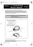
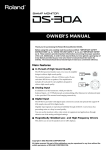
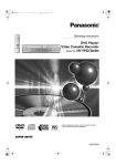
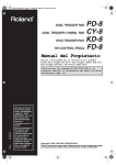
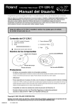
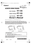
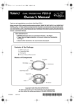
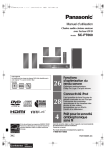
PD-80/PD-80RW.e2 1 ページ 2004年6月11日 金曜日 午前10時12分
Owner's Manual
Thank you, and congratulations on your choice of the Roland PD-80/PD-80R V-Pad.
201a
Before using this unit, carefully read the sections entitled: “USING THE UNIT SAFELY” (p. 3–4) and
“IMPORTANT NOTES” (p. 4). These sections provide important information concerning the proper
operation of the unit. Additionally, in order to feel assured that you have gained a good grasp of every
feature provided by your new unit, Owner’s manual should be read in its entirety. The manual should be
saved and kept on hand as a convenient reference.
Before using the PD-80/PD-80R, you need to make the following settings.
• Head tension adjustment (p. 5)
• Settings for the percussion sound module (p. 2)
Contents of the Package
❑
❑
❑
■
PD-80 or PD-80R (pad unit)
Connection Cable
Tuning Key
Owner's Manual (this manual)
Names of Components
Hoop (Rim)
Sensor
Head
Washer
Stand Fixing Screw
Tuning Bolt
Output Jack
Holder
Frame
Copyright © 2003 ROLAND CORPORATION
All rights reserved. No part of this publication may be reproduced in any form without the
written permission of ROLAND CORPORATION.
03458956
2RCC
202
PD-80/PD-80RW.e2 2 ページ 2004年6月11日 金曜日 午前10時12分
Recommended Settings for the Percussion Sound Module
Recommended settings for the trigger parameters when using the PD-80/PD-80R with various percussion sound
modules.
•
•
•
•
When used with a percussion sound module capable of positional sensing, you can obtain tonal changes by varying the location
at which the pad is struck.
You can perform rim shots and cross-sticking with the PD-80R. For information on sound generator and trigger input
combinations, refer to p. 6.
The trigger parameters should be adjusted as necessary to match the actual state of your configuration, and the environment in
which it is being used.
For information on how to change the parameters for a percussion sound module. Refer to the documentation for the percussion
sound module you’re using.
TD-10 (TDW-1 V-Cymbal Control, TDW-1)
Trigger Type
Sensitivity
Threshold
Curve
Scan Time
Retrigger Cancel
Mask Time
Xtalk Cancel
Mount Type
Xstick Thrshld
Rim Sens
(*1)
(*1)
(*1)
(*1)
(*1)
TD-7(*2)
PD-80: 8 A or 8 B, PD-80R: 8RA or 8RB
5
2
Linear
1.8
4
8
50
PadMount
75 (PD-80R only)
8 (PD-80R only)
Cross Talk Group
Velocity Curve
Choke
Max Dyna
MIn Dyna
Min Velo
Mask Time
Threshold
TD-5
TRIGGER TYPE
SENSITIVITY
THRESHOLD
CURVE
TD-10 (Non expanded)
Trigger Type
Sensitivity
Threshold
Curve
Scan Time
Retrigger Cancel
Mask Time
Xtalk Cancel
Rim Sens
(*1)
(*1)
(*1)
(*1)
12A
3
1
Linear
1.8
3
12
OFF
8 (PD-80R only)
TRIG SENS
TRIG THRESHOLD
8
0ß40
TRIG TYPE
TRIG CURVE
RIM SENS
120
1
1 (PD-80R only)
SPD-11
Trig Sens
Trig Threshold
Trig Mask Time
Trig Scan Time
PD-80: 8 A or 8 B, PD-80R: 8RA or 8RB
7
3
LINEAR
8 (PD-80R only)
PD-80R: 2, PD-80: 1
3
0
45
5 (PD-80R only)
8
1
0
20
SPD-S
Input Mode
Trigger Type
Sensitivity
Threshold
Velocity Curve
Scan Time
Retrigger Cancel
Mask Time
Xtalk Cancel
Rim Sensitivity
Rim Gain
TD-6V
TrigType
Sensitivity
Threshold
TrigCurve
Xtalk Cancel
Scan Time
Retrig Cancel
Mask Time
Rim Sens
P1
4
1
Lnr
SPD-20
TD-8
TRIGGER TYPE
SENSITIVITY
THRESHOLD
CURVE
RIM SENS
SCAN TIME
RETRIGCANCL
MASK TIME
CROSSTALK
CROSS STICK
OFF
Norm3
OFF
5
9
1
0
1
PD-80: PD80/100, PD-80R: PD80R
8
PD-80R: 3, PD-80: 1
LINEAR
40
1.0
3
4
11 (PD-80R only)
PD-80: TRIGx2, PD-80R: HD/RM
PD-80: PD-80/100, PD-80R: PD-80R
8
PD-80: 3, PD-80R: 2
LINEAR
1.0
PD-80: 4, PD-80R: 3
4
30
11 (PD-80R only)
1.2 (PD-80R only)
HPD-15
Input Mode
Trig Type
Trig Sens
Curve
Threshold
Scan Time
Retrig Cancel
Mask Time
X-Talk Rate
Rim Sens
PD-80: TRIGx2, PD-80R: HD/RM
PD-80: PD-80, PD-80R: PD-80R
8
Linear
2
1ms
2
2ms
50%
8 (PD-80R only)
*1: You need to set each advanced trigger parameter after setting the trigger type.
*2: Each trigger parameter can be set independently for the “head-side” and “rim-side.” Set to the same value for the head and rim.
Trigger parameters can be set individually for each patch.
2
PD-80/PD-80RW.e2 3 ページ 2004年6月11日 金曜日 午前10時12分
USING THE UNIT SAFELY
The
symbol alerts the user to important instructions
or warnings.The specific meaning of the symbol is
determined by the design contained within the
triangle. In the case of the symbol at left, it is used for
general cautions, warnings, or alerts to danger.
Used for instructions intended to alert
the user to the risk of death or severe
injury should the unit be used
improperly.
Used for instructions intended to alert
the user to the risk of injury or material
damage should the unit be used
improperly.
* Material damage refers
other adverse effects
respect to the home
furnishings, as well
animals or pets.
001
•
The
symbol alerts the user to items that must never
be carried out (are forbidden). The specific thing that
must not be done is indicated by the design contained
within the circle. In the case of the symbol at left, it
means that the unit must never be disassembled.
to damage or
caused with
and all its
to domestic
The ● symbol alerts the user to things that must be
carried out. The specific thing that must be done is
indicated by the design contained within the circle. In
the case of the symbol at left, it means that the powercord plug must be unplugged from the outlet.
006
•
Before using this unit, make sure to read the
instructions below, and the Owner’s Manual.
................................................................................................
002a
•
Do not open or perform any internal modifications
on the unit. (The only exception would be where
this manual provides specific instructions which
should be followed in order to put in place userinstallable options; see p. 7.)
................................................................................................
011
•
................................................................................................
003
•
Do not attempt to repair the unit, or replace parts
within it (except when this manual provides
specific instructions directing you to do so). Refer
all servicing to your retailer, the nearest Roland
Service Center, or an authorized Roland
distributor, as listed on the attached “Information”
leaflet.
•
Do not allow any objects (e.g., flammable material,
coins, pins); or liquids of any kind (water, soft
drinks, etc.) to penetrate the unit.
................................................................................................
013
•
................................................................................................
004
When using the unit with a rack or stand recommended by Roland, the rack or stand must be
carefully placed so it is level and sure to remain
stable. If not using a rack or stand, you still need to
make sure that any location you choose for placing
the unit provides a level surface that will properly
support the unit, and keep it from wobbling.
In households with small children, an adult should
provide supervision until the child is capable of
following all the rules essential for the safe
operation of the unit.
................................................................................................
Never use or store the unit in places that are:
014
•
• Subject to temperature extremes (e.g., direct
sunlight in an enclosed vehicle, near a heating
duct, on top of heat-generating equipment); or
are
• Damp (e.g., baths, washrooms, on wet floors); or
are
• Humid; or are
• Exposed to rain; or are
• Dusty; or are
• Subject to high levels of vibration.
Protect the unit from strong impact.
(Do not drop it!)
................................................................................................
•
To avoid personal injury and/or damage to the
unit, do not touch anything inside the frame of the
PD-80 and PD-80R.
................................................................................................
................................................................................................
005
•
This unit should be used only with a rack or stand
that is recommended by Roland.
................................................................................................
3
Next
PD-80/PD-80RW.e2 4 ページ 2004年6月11日 金曜日 午前10時12分
104
•
Try to prevent cords and cables from becoming
entangled. Also, all cords and cables should be
placed so they are out of the reach of children.
•
................................................................................................
106
•
Never climb on top of, nor place heavy objects on
the unit.
................................................................................................
................................................................................................
118
•
•
Should you remove lock-nut, spacer, rubber
spacer, washer, or tuning bolt, etc., make sure to
put them in a safe place out of children's reach, so
there is no chance of them being swallowed accidentally.
................................................................................................
•
The PD-80 and PD-80R are shipped from the
factory with the head tension loosened. Be sure to
tighten the tension before use. Striking the head
when the head tension is loose may damage the
sensor and head.
................................................................................................
Do not apply excessive force to the sensor located
below the center of the head. Doing so can interfere
with accurate detection, and may damage it.
•
................................................................................................
•
Brushes can be used to play the PD-80 and PD-80R
when the TD-8 and TD-10 are used as the sound
module. When using brushes, be sure to use nylon
brushes. Using metal brushes will not only scratch the
head, but can also be hazardous, since the tip of the brush
may catch in the mesh of the net.
Due to the nature of the materials used in the
sensor, changes in room temperature may affect
the sensitivity of the sensor.
................................................................................................
The hoop's rubber portion is one component that
eventually wears out (the more so if numerous rim
shots are performed), and will require
replacement.
Rim shots may not be performed correctly when
the rubber portion is worn out. If this occurs,
replace the hoop rubber. Consult Roland Service
for more on replacing the hoop rubber.
................................................................................................
IMPORTANT NOTES
291a
In addition to the items listed under “USING THE UNIT SAFELY” on page 3–4, please read and observe the
following:
Placement
Additional Precautions
354b
553
•
Do not expose the unit to direct sunlight, place it near
devices that radiate heat, leave it inside an enclosed
vehicle, or otherwise subject it to temperature extremes.
Also, do not allow lighting devices that normally are used
while their light source is very close to the unit (such as a
piano light), or powerful spotlights to shine upon the
same area of the unit for extended periods of time.
Excessive heat can deform or discolor the unit.
•
Do not allow rubber, vinyl, or similar materials to remain
on the unit for long periods of time. Such objects can
discolor or otherwise harmfully affect the finish.
•
556
•
Maintenance
401a
•
For everyday cleaning wipe the unit with a soft, dry cloth
or one that has been slightly dampened with water. To
remove stubborn dirt, use a cloth impregnated with a
mild, non-abrasive detergent. Afterwards, be sure to wipe
the unit thoroughly with a soft, dry cloth.
402
•
When connecting / disconnecting all cables, grasp the
connector itself—never pull on the cable. This way you
will avoid causing shorts, or damage to the cable’s
internal elements.
558d
356
•
Use a reasonable amount of care when using the unit’s
buttons, sliders, or other controls; and when using its jacks
and connectors. Rough handling can lead to malfunctions.
Never use benzine, thinners, alcohol or solvents of any
kind, to avoid the possibility of discoloration and/or
deformation.
4
This instrument is designed to minimize the extraneous
sounds produced when it’s played. However, since sound
vibrations can be transmitted through floors and walls to a
greater degree than expected, take care not to allow these
sounds to become a nuisance to neighbors, especially
when performing at night and when using headphones.
PD-80/PD-80RW.e2 5 ページ 2004年6月11日 金曜日 午前10時12分
Features
• On the PD-80/80R, adjusting the head tension affects
only the head response, and does not change the pitch of
the sound, as it would on an acoustic drum.
• The head tension will change as the instrument is used,
so you should readjust when necessary.
• The head stretches when used for extended periods, so
even when this is adjusted to 7 mm in the following
procedure, you may not achieve the same degree of
tension as when the head was initially adjusted. Strike
the head to check the feel and response as you adjust the
tension.
• Snare/tom pad with embedded-mesh head for
superior playing feel, and quiet response.
• Compact, eight-inch pad allows for greater
versatility when setting up.
• The PD-80R incorporates a rim sensor, for
expressive capabilities rivaling an acoustic snare
drum.
• Once you connect the PD-80 or PD-80R to Trigger
Input 3 (SNARE) on a TD-8 Percussion Sound
Module, you will be able to enjoy enhanced
capabilities, as follows.
1. Use the included tuning key to tighten the
tuning bolts.
Tighten the bolts until there is a space of
approximately 7 mm between the frame and the
hoop.
• Tonal changes can be expressed by varying the
location at which the pad is struck.
• Brushes (nylon) can be used for brush playing.
• On the PD-80R you can use cross-stick (closed rim
shot), and rim shot playing techniques.
fig.P07.e
Hoop
Adjusting the Head
7mm
Adjusting the Head Tension
When adjusting, use the included tuning key.
Frame
The PD-80 and PD-80R are shipped from
the factory with the head tension
loosened. Be sure to adjust the tension
before use.
A black, 7 mm strip is printed at the edge of this page.
Use this as a reference when making the adjustment.
In general, a tension that produces a strike response
approximately the same as an acoustic drum will be
appropriate.
•
Striking the head when the head tension is loose
may damage the sensor and head.
Should you neglect to make the appropriate
settings, you could likely experience the
following problems:
Sometimes it does not sound (uneven volume).
The volume is too low (reduced sensitivity).
fig.P03
3
1
5
4
7mm
•
Tighten each tuning bolt one by one, observing the
numerical order shown in the diagram.
Do not firmly tighten a single tuning bolt by itself. Doing
so will make it impossible to tension the head evenly, and
will cause malfunctions such as failure to accurately
detect the striking location.
The band has a width of 7 mm.
Use this for adjusting the head tension.
2
2. Fine-tune the adjustment while continuing to
check the pad feel and response.
5
Next
PD-80/PD-80RW.e2 6 ページ 2004年6月11日 金曜日 午前10時12分
Connecting to the Percussion
Sound Module
Adjustment for Positional Sensing
with the TD-8 or the TD-10
When the TD-8 or the TD-10 is used as the sound module, the
location at which the pad is struck can be varied to produce
tonal changes. In this case, it is important to adjust the head so
the tension is evenly distributed, so the striking location can be
detected accurately. For details on adjustments, refer to the TD8 or the TD-10 owner’s manual.
921
To prevent malfunction and/or damage to speakers or other
devices, always turn down the volume, and turn off the power
on all devices before making any connections.
When you have finished connecting to your drum sound
module, refer to the recommended parameters on p. 2, and
make the settings for the sound module.
The TD-10 owner’s manual assumes use of the PD-100 and
PD-120 pads in its explanation. If you are using the PD-80 or
PD-80R, however, make adjustments while striking them 1
inch (3 cm) from the rim.
Sound Module
Trigger inputs that allow
positional sensing
TD-8
3 (SNARE)
TD-10
2 (SNARE)
Connecting to the TD-6V, TD-8, TD-10,
HPD-15, SPD-20, or SPD-S
• Use the included cable to make connections.
• With the PD-80R, make sure to use the supplied stereo
cable when connecting it. Otherwise (if you use a
monaural cable), you won’t be able to employ striking
location detection, rim shot, and cross stick playing
techniques.
• Connect the L-shaped plug of the included cable to the
PD-80/80R. This will prevent strain from being applied
to the PD-80/80R.
Attaching the Pad to a Stand
Attach the PD-80 or PD-80R to a stand (MDS series).
fig.P02.e
Tighten
Correspondences Between Playing
Techniques and Percussion Sound Modules
Loosen
Rod
Pass the rod through the pipe
that is inside the holder.
When attaching the PD-80/80R to a tom stand, check the
dimensions of the rod. Depending on the dimensions of the
rod, it may not be possible to attach the pad to the stand.
Rim
Shot
Cross
Stick
Positional
Sensing
Sound
Module
Trigger
Input
TD-6V
2 (SNARE)
o
o
–
TD-8
3 (SNARE)
o
o
o
TD-10
2 (SNARE)
o
–
o
TD-10
(TDW-1)
2 (SNARE)
o
o
o
HPD-15
1, 2
o
–
–
SPD-20
1, 2
o
–
–
SPD-S
1, 2
o
–
–
* Rim shots and cross-stick performances can be made only with the
PD-80R.
Acceptable rod diameters:
8.5–11.5 mm (3/8 to 1/2 inch)
Connecting to the TD-5, TD-7 or SPD-11
• Use the included cable to make connections.
• Connect the L-shaped plug of the included cable to the
PD-80/80R.
This will prevent strain from being applied to the PD-80/
80R.
• It is not possible to play rim shots even if you connect the
PD-80R to the TD-5, TD-7, or SPD-11.
6
Next
PD-80/PD-80RW.e2 7 ページ 2004年6月11日 金曜日 午前10時12分
Replacing the Head
About the PD-80R's Lock Bushings
The PD-80R is provided with lock bushings to prevent rotation
and loosening of the tuning bolts caused by vibration
transmitted from the hoop, as the result of using rim shots or
other performance techniques.
If a lock bushing happens to become separated from the frame
while the head is being replaced, position the bushing so its
four slots are aligned with the corresponding ridges in the
frame, then press down firmly on the bushing.
When the Head Should Be Replaced
The head is an expendable item that eventually will wear out
and need to be replaced. Replace the head when the following
occurs:
• The head surface is torn
• Striking points are no longer detected correctly, even
when the head tension is properly adjusted.
• Slack portions remain in the head even after the head
tension is properly adjusted.
fig.P06.e
Lock Bushing
Replacement heads (optional)
MH-8 Mesh Head: for either PD-80 or PD-80R
Frame
Replacing the Head
1. Remove all tuning bolts and washers.
Specifications
If using the PD-80R, press the lock bushing (in figure
below) in place with your finger as you remove each
tuning bolt, to prevent the bushings from being pulled off
the frame.
PD-80 (Pad)
Pad Size:
8 inches
Trigger:
1 (Head)
Dimensions: 245 (W) x 310 (D) x 95 (H) mm
9-11/16 (W) x 12-1/4 (D) x 3-3/4 (H) inches
Weight:
1.6 kg
3 lbs 8 oz
Accessories: Owner’s Manual, Connection Cable, Tuning Key
Options:
Mesh Head (MH-8),
Pad Mounts (MDH-7U, MDH-10),
Drum Stands (MDS-3C, MDS-6, MDS-8C,
MDS-10, MDS-20)
fig.P05.e
Tuning Key
Hoop's
Rubber Portion
Tuning Bolt
Washer
Hoop
Lock Bushing
PD-80R (Pad)
Pad Size:
8 inches
Triggers:
2 (Head, Rim)
Dimensions: 245 (W) x 310 (D) x 95 (H) mm
9-11/16 (W) x 12-1/4 (W) x 3-3/4 (H) inches
Weight:
1.7 kg
3 lbs 12 oz
Accessories: Owner's Manual, Connection Cable, Tuning Key
Options:
Mesh Head (MH-8),
Pad Mounts (MDH-7U, MDH-10),
Drum Stands (MDS-3C, MDS-6, MDS-8C,
MDS-10, MDS-20)
Frame
For more on the lock bushings, refer to the following section,
“About the PD-80R's Lock Bushings.”
2. Remove the hoop.
3. Remove the old head.
4. Place the new head on the frame.
5. Place the hoop onto the head.
6. Pass the tuning bolts through the washers,
then attach them to the hoop and frame.
962a
7. Next, adjust the tension of the head. Refer to
“Adjusting the Head Tension” (p. 5).
In the interest of product improvement, the specifications
and/or appearance of this unit are subject to change without
prior notice.
Do not firmly tighten a single tuning bolt by itself. Doing so
will make it impossible to tension the head evenly, and will
cause malfunctions such as failure to accurately detect the
striking location.
7
PD-80/PD-80RW.e2 8 ページ 2004年6月11日 金曜日 午前10時12分