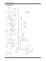
1
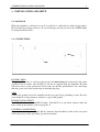
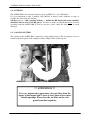
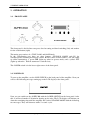
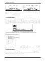
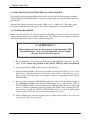
REIMESCH KOMMUNIKATIONSSYSTEME GMBH
ALPIN 200
- HF Linear Amplifier -
USER MANUAL
v1.0
DECLARATION OF CONFORMITY
I hereby declare that the product:
ALPIN 200, HF 2kW Linear Amplifier
satisfies all the technical regulations applicable to the product within the scope of Council
Directives 73/23/EEC, 89/336/EEC and 99/5/EC:
EN 301 783-1 V1.1.1 (2000-09), EN 301 783-2 V1.1.1 (2000-09)
EN 301 489-1 V1.4.1 (2002-08), EN 301 489-15 V1.4.1 (2002-08)
EN 60215 (August 1994)
All essential radio test suites have been carried out.
MANUFACTURER or AUTHORISED REPRESENTATIVE:
- Address:
Reimesch Kommunikationssysteme GmbH
Friedrich-Ebert-Straße
D-51427 Bergisch Gladbach
Deutschland (Germany)
This declaration is issued under the sole responsibility of the manufacturer and, if
applicable, his authorised representative:
- Contact:
Christian Reimesch, Tel. +49 2204 584751 and Fax. +49 2204 584767
Bergisch Gladbach, 16.01.08
(Christian Reimesch, CEO)
ALPIN200 Manual © Copyright 2008 by Reimesch Kommunikationssysteme GmbH
TECHNICAL DATA
Frequency coverage
Drive power
Output power
Power Gain
Input Attenuator
SWR Range
Harmonics
High Voltage
Intermodulation distortion
Tube
supply voltage
Dimensions
Weight
AC-Power
all Amateur Radio Bands 1.8-29.7 MHz
60W
2000 Watts continuous
15dB
6dB
1:3 (16..150Ohm)
1.8-29.7 MHz > 50dB
abt. 2550V under Load at 230VDC input
> 35dB
2 x 4CX800A (GU74B) forced air cooling
230 VAC – 50Hz ,one phase
(W x D x H) (470mm x 415mm x 190mm)
40 kg
Fused at 20 A max.
ALPIN200 Manual © Copyright 2008 by Reimesch Kommunikationssysteme GmbH
CONTENTS
1.
INSTALLATION AND SETUP......................................................................................... 5
1.1. PACKAGE .................................................................................................................. 5
1.2. CONNECTIONS ......................................................................................................... 5
1.3. TRANSFORMER ........................................................................................................ 7
1.4. ANTENNA .................................................................................................................. 8
1.5. COOLING SYSTEM .................................................................................................. 8
2. OPERATION ...................................................................................................................... 9
2.1. FRONT PANEL .......................................................................................................... 9
2.2. POWER ON ................................................................................................................ 9
2.3. STANDBY MODE.................................................................................................... 10
2.4. OPERATE MODE .................................................................................................... 10
2.5. ELECTRONIC BIAS SYSTEM (EBS) only ALPIN 200 MK II ............................. 11
2.6. TUNING PROCEDURE ........................................................................................... 11
2.7. TUNING EXAMPLE ................................................................................................ 12
2.8. TUNE TABLE ........................................................................................................... 13
3. PROTECTION SYSTEM ................................................................................................. 14
3.1. Errors in Power On mode: ......................................................................................... 14
3.2. Errors in Standby mode: ............................................................................................ 14
3.3. Errors in Operate mode: ............................................................................................ 15
3.4. Errors in TX/RX mode: .............................................................................................. 15
3.5. Warnings in Operate mode: ...................................................................................... 15
4. SCHEMATIC ................................................................................................................... 16
ALPIN200 Manual © Copyright 2008 by Reimesch Kommunikationssysteme GmbH
5 EXHIBIT INSTALLATION AND SETUP
5
1. INSTALLATION AND SETUP
1.1. PACKAGE
When the amplifier is delivered to you it is packed in a cardboard box with styropor inlays.
Please handle the package with care. In case of damage you may need it for the ALPIN 200 to
be transported back safely.
1.2. CONNECTIONS
POWER CABLE
The green-yellow wire is a chassis safety ground and must always be connected to the safety
ground of the AC mains. (the AC-PLUG will not be supplied with the amplifier) The blue
and brown wires are the powerleads. Please take care that the groundlead be cut a bit longer
than the power leads (blue and brown) at installing the plug.
GND
Connect the ground stud of the amplifier on the rear panel to the grounding system. The wire
used should be of large diameter and run to a good earth ground.
RF INPUT AND OUTPUT
Use a 50 Ohm coax cable with PL259 plugs. Take RG 213 or any better antenna cable and
have a look on the antenna section on page no. 9.
CONTROL CONNECTIONS
Use a shielded cable with a Phono (RCA) connector from the Relay socket on the rear panel
to the transceiver socket, providing "ground on transmit".
ALPIN200 Manual © Copyright 2008 by Reimesch Kommunikationssysteme GmbH
5 EXHIBIT INSTALLATION AND SETUP
6
SETUP
1) Connect the RF-Input connector from the ALPIN 200 to the Transceiver Antenna Port
(TRX IN/Out).
2) Connect a suitable antenna or artificial load being able to handle the output power
delivered by the ALPIN 200.
3) Connect the PTT – Line from your transceiver to the RELAY jack of the ALPIN 200.
The voltage on the Relay Jack is 12V and the current to ground is 11mA.
4) For QSK Operation connect your KEYER to the “RELAY” Jack and connect the KEY
OUT jack on the rear of the ALPIN 200 to the KEY INPUT of your transceiver.
5) Connect the amplifier to the AC – Mains (230VAC) and switch on the MAINS
POWER SWITCH on the rear of the ALPIN 200.
ALPIN200 Manual © Copyright 2008 by Reimesch Kommunikationssysteme GmbH
5 EXHIBIT INSTALLATION AND SETUP
1.3. TRANSFORMER
!!! ATTENTION !!!
To avoid any damages, please remove the transformer
before shipping.
ASSEMBLING AND DISMOUNTING
It is very easy to assemble or to remove the plug-in transformer. There are only very few
connections and screws to other parts of the amplifier.
The Following parts have to be (dis)connected:
• 6 pin plug socket to the high voltage board (only 2 pins connected)
• 9 pin plug socket to main board and G1/G2 board
• 2 pin plug socket to tube deck
• 4 screws on the bottom of the box
ALPIN200 Manual © Copyright 2008 by Reimesch Kommunikationssysteme GmbH
7
5 EXHIBIT INSTALLATION AND SETUP
8
1.4. ANTENNA
The ALPIN 200 is able to match antennas up to an SWR of 1:3 (16..150 Ohms).
It is very important to take a suitable cable (RG213 or better) with a diameter as large as
possible for connecting the antenna.
All the rest ( i.e. : cable, antenna, balloon…) behind the RF output jack of the amplifier
should be able to resist 1 kW RF power. You have to make sure about this before you start
operating with the ALPIN 200. If you are not sure, please check the data sheets to avoid
damages.
1.5. COOLING SYSTEM
The cooling of the ALPIN 200 is realized by a high-quality blower. The air input port is to be
found on the back panel of the amplifier and the output outlet on the top side.
!!! ATTENTION !!!
It is very important to guarantee a free air flow from the
input- to the output side. Leave at least 20cm of free space
to both openings. Please free the air filter on the rear
panel from dust regularly.
ALPIN200 Manual © Copyright 2008 by Reimesch Kommunikationssysteme GmbH
5 EXHIBIT OPERATION
9
2. OPERATION
2.1. FRONT PANEL
The front panel is divided into two parts: One for tuning and band switching (left) and another
for the visualization.(right)
The tuning part consists of a TUNE, LOAD and BAND knob.
In the visualization part there are three buttons: STBY/OPR, DOWN and UP for
standby/operate switching and display control. Besides, there are three LEDs: a red TX (lights
up when transmitting), a green OPR (lights up when in operate mode) and a yellow ATT
(lights up when the built-in attenuator is switched on).
The POWER switch is in the lower right corner of the front panel.
2.2. POWER ON
To start up the amplifier, use the LINE SWITCH on the back panel of the amplifier. Now you
will see the following message coming up on the LCD display at the front panel:
Now you can switch on the ALPIN 200 with the POWER SWITCH on the front panel. After
this, it will need another 2:30 min for heating up the tube. The LCD display will inform you
about the remaining time until the amplifier has reached STANDBY MODE with the following
two messages. They will alternate with a 5-second- cycle.
ALPIN200 Manual © Copyright 2008 by Reimesch Kommunikationssysteme GmbH
5 EXHIBIT OPERATION
10
While the amplifier is heating up, the protection system will monitor all the important data.
Please have a look at page 15 for more information.
2.3. STANDBY MODE
When the warming-up time is over, the ALPIN 200 will move to standby mode. Here you can
see the forward power for the first time, the reflected power, and the CAP meter. The fourth
row of the display is used to show individual and /or the most essential values of the
amplifier.
You may alter the displayed data with the UP and DOWN buttons next to the display.
The Following data will be shown:
•
•
•
•
•
•
•
•
Forward power
Temperature of the exhaust air
Drive RF power
Screen current
High voltage
Plate current
Antenna SWR
Reflected power
In standby mode the following values are measured: temperature of exhaust air, screen
current and high voltage. You can see all the values either in operate mode or in transmit
mode.
2.4. OPERATE MODE
To enter the operate mode press the OPR/STBY button. After this, the green OPR LED will
light. Only in this mode you will be able to transmit.
ALPIN200 Manual © Copyright 2008 by Reimesch Kommunikationssysteme GmbH
5 EXHIBIT OPERATION
11
2.5. ELECTRONIC BIAS SYSTEM (EBS) only ALPIN 200 MK II
The amplifier has an integrated EBS which can be activated and deactivated after switching
on. The buttons UP and DOWN have to be pressed down while pressing the LINE switch on
the backside.
After this the display will show the message “EBS is on” or “EBS is off”. The status can be
changed by doing this procedure again. The default configuration is an activated EBS.
2.6. TUNING PROCEDURE
Below, you can find a step-by-step description of the tuning procedure. It may vary from one
band to another, but these are the basic things to do. For a better and faster tuning use the tune
table in the following section to find a rough starting point.
!!! ATTENTION !!!
Before tuning decrease the drive power to approximately 20W
to avoid damages! After you have found the correct tuning,
you may increase the drive power.
1) Set the Amplifier to the desired band with the BAND SWITCH on the left of the front
panel. Never change the position of the BAND SWITCH while transmitting!
2) Apply approximately 20W of drive power to the amplifier.
3) Tune the LOAD KNOB on the front panel while observing the CAP tune meter on the
LCD display. Turn the knob into the direction of the arrows of the CAP tune meter.
Please use the tune table in the next chapter for the first configuration of TUNE and
LOAD KNOBs.
4) Now we have to turn the TUNE KNOB on the front panel to the maximum reading of
the FORWARD POWER in the display. While tuning it is possible that the built- in
INPUT ATTENUATOR is activated and the ATT LED will light. Don’t care about that
and try to find the optimum position for LOAD and TUNE. After releasing the PTT
and pressing it again the INPUT ATTENUATOR will be deactivated again (when
tuning is good) and in the next step some fine tuning can be done.
5) After readjusting the transceiver output power a slight retune could be necessary and
steps 4) and 5) have to be repeated.
ALPIN200 Manual © Copyright 2008 by Reimesch Kommunikationssysteme GmbH
5 EXHIBIT OPERATION
12
2.7. TUNING EXAMPLE
You can find an example of the tuning procedure below.
The LOAD TUNIG KNOB has to be rotated
clockwise.
While rotating the LOAD capacitor the CAP
METER is close to the optimum tuning
point.
We are next to the optimum point. Just a
small correction of LOAD and TUNE will
be necessary to reach the point.
Here, we have found the optimum point for
the LOAD Capacitor. Now we can release
the PTT and increase the drive power.
After pressing the PTT again it might be
possible to readjust the amplifier a bit.
ALPIN200 Manual © Copyright 2008 by Reimesch Kommunikationssysteme GmbH
5 EXHIBIT OPERATION
13
2.8. TUNE TABLE
The table below shows the approximate settings for the TUNE and LOAD knobs on each
band. These settings are not exact but they can give you a starting point for a faster tuning
of the amplifier.
Band
1.8
3.56
7.05
10.1
14.25
18.15
21.25
24.92
28.5
50.2
Tune
66
29
49
15
44
87
39
57
22
15
Load
85
48
81
30
38
81
56
54
39
14
These settings will vary from one amplifier to another.
ALPIN200 Manual © Copyright 2008 by Reimesch Kommunikationssysteme GmbH
5 EXHIBIT PROTECTION SYSTEM
14
3. PROTECTION SYSTEM
This amplifier uses a very complex protection system. If an error occurs, the amplifier
switches to standby or off mode and prints an error code to the display.
In this way, the protection system is able to avoid a series of potential damages to the
amplifier, but there is no reason to operate carelessly.
3.1. Errors in Power On mode:
Code
17
18
19
20
21
22
23
24
25
Legend
average plate voltage too high
IG2 too high
plate current too high
grid RF too high
problem with output relay contact
screen current too high
HV < 350V for more than 120 ms
HV > 3300V or HV < 1500V
low air for > 90 s
3.2. Errors in Standby mode:
Code
33
34
35
36
37
38
39
40
41
42
Legend
plate current > 25mA
high voltage > 3300V or high voltage < 1500V
temperature > 115°C
problem with output relay contact
G1 screen current
low air for > 90 s
problem in low voltage supply
drive power > 0.44W
average plate voltage > 480V
G2 screen current > 5mA
ALPIN200 Manual © Copyright 2008 by Reimesch Kommunikationssysteme GmbH
5 EXHIBIT PROTECTION SYSTEM
15
3.3. Errors in Operate mode:
Code
49
50
51
52
Legend
plate current > 1.2 A
problem in low voltage supply
low air for > 90 s
HV > 3300V or HV < 1500V
3.4. Errors in TX/RX mode:
Code
64
66
67
68
Legend
problem with output relay contact
output relay contact switch 5ms problem
output relay contact switch 5ms problem
Grid RF and PANT are not ok
3.5. Warnings in Operate mode:
Besides those errors there are some warnings in the Operate mode. The amplifier shows a
flashing warning message and/or will switch to Standby mode.
Message
Legend
Action
REFLECTED PWR
Reflected power > 350W
Standby mode
DRIVE TOO HIGH
Drive power > 90W for less than 5 s
Drive power > 90W for more than 5s
Drive power > 120W
Warning
Standby mode
Standby mode
SCREEN CURRENT
Screen current > 80mA for more than 1s
Standby mode
PLATE CURRENT
Plate current > 700mA
Plate current > 800mA for more than 2s
Warning
Standby mode
OVERHEATING
Temperature > 97°C ( 207° F)
Temperature > 115°C ( 239° F)
Warning
Standby mode
ARC FAULT
Recognized arc
Standby mode
GRID CURRENT
Grid current too high
Standby mode
ALPIN200 Manual © Copyright 2008 by Reimesch Kommunikationssysteme GmbH
5 EXHIBIT SCHEMATIC
4. SCHEMATIC
ALPIN200 Manual © Copyright 2008 by Reimesch Kommunikationssysteme GmbH
16