1
Altivar 32
Variable speed drives
for synchronous and asynchronous motors
Programming Manual
S1A28692
03/2010
www.schneider-electric.com
Courtesy of Steven Engineering, Inc.-230 Ryan Way, South San Francisco, CA 94080-6370-Main Office: (650) 588-9200-Outside Local Area: (800) 258-9200-www.stevenengineering.com
The information provided in this documentation contains general descriptions and/or technical characteristics
of the performance of the products contained herein. This documentation is not intended as a substitute for
and is not to be used for determining suitability or reliability of these products for specific user applications. It
is the duty of any such user or integrator to perform the appropriate and complete risk analysis, evaluation and
testing of the products with respect to the relevant specific application or use thereof. Neither Schneider
Electric nor any of its affiliates or subsidiaries shall be responsible or liable for misuse of the information
contained herein. If you have any suggestions for improvements or amendments or have found errors in this
publication, please notify us.
No part of this document may be reproduced in any form or by any means, electronic or mechanical, including
photocopying, without express written permission of Schneider Electric.
All pertinent state, regional, and local safety regulations must be observed when installing and using this
product. For reasons of safety and to help ensure compliance with documented system data, only the
manufacturer should perform repairs to components.
When devices are used for applications with technical safety requirements, the relevant instructions must be
followed.
Failure to use Schneider Electric software or approved software with our hardware products may result in
injury, harm, or improper operating results.
Failure to observe this information can result in injury or equipment damage.
© 2010 Schneider Electric. All rights reserved.
2
S1A28692 03/2010
Courtesy of Steven Engineering, Inc.-230 Ryan Way, South San Francisco, CA 94080-6370-Main Office: (650) 588-9200-Outside Local Area: (800) 258-9200-www.stevenengineering.com
Table of Contents
Table of Contents
Safety Information . . . . . . . . . . . . . . . . . . . . . . . . . . . . . . . . . . . . . . . . . . . . . . . . . . . . 7
About the Book . . . . . . . . . . . . . . . . . . . . . . . . . . . . . . . . . . . . . . . . . . . . . . . . . . . . . . . 8
General Overview . . . . . . . . . . . . . . . . . . . . . . . . . . . . . . . . . . . . . . . . . . . . . . . . . . . . . . . . . . 11
Chapter 1
Setup . . . . . . . . . . . . . . . . . . . . . . . . . . . . . . . . . . . . . . . . . . . . . . . . . . . . . . . . . . . . . . . 13
Steps for setting-up the drive . . . . . . . . . . . . . . . . . . . . . . . . . . . . . . . . . . . . . . . . . . . . 14
Preliminary recommendations . . . . . . . . . . . . . . . . . . . . . . . . . . . . . . . . . . . . . . . . . . . 15
Chapter 2
Overview . . . . . . . . . . . . . . . . . . . . . . . . . . . . . . . . . . . . . . . . . . . . . . . . . . . . . . . . . . . . 17
Factory configuration . . . . . . . . . . . . . . . . . . . . . . . . . . . . . . . . . . . . . . . . . . . . . . . . . . 18
Application functions. . . . . . . . . . . . . . . . . . . . . . . . . . . . . . . . . . . . . . . . . . . . . . . . . . . 19
Basic functions . . . . . . . . . . . . . . . . . . . . . . . . . . . . . . . . . . . . . . . . . . . . . . . . . . . . . . . 23
Graphic display terminal option . . . . . . . . . . . . . . . . . . . . . . . . . . . . . . . . . . . . . . . . . . 24
Powering up the drive for the first time . . . . . . . . . . . . . . . . . . . . . . . . . . . . . . . . . . . . . 27
Remote display terminal option . . . . . . . . . . . . . . . . . . . . . . . . . . . . . . . . . . . . . . . . . . 30
Structure of the parameter tables . . . . . . . . . . . . . . . . . . . . . . . . . . . . . . . . . . . . . . . . . 31
Finding a parameter in this document . . . . . . . . . . . . . . . . . . . . . . . . . . . . . . . . . . . . . 32
Description of the HMI . . . . . . . . . . . . . . . . . . . . . . . . . . . . . . . . . . . . . . . . . . . . . . . . . 33
Structure of the menus . . . . . . . . . . . . . . . . . . . . . . . . . . . . . . . . . . . . . . . . . . . . . . . . . 34
Programming . . . . . . . . . . . . . . . . . . . . . . . . . . . . . . . . . . . . . . . . . . . . . . . . . . . . . . . . . . . . . . 35
Chapter 3
Reference Mode (rEF) . . . . . . . . . . . . . . . . . . . . . . . . . . . . . . . . . . . . . . . . . . . . . . . . . 37
Introduction . . . . . . . . . . . . . . . . . . . . . . . . . . . . . . . . . . . . . . . . . . . . . . . . . . . . . . . . . . 38
Organization tree . . . . . . . . . . . . . . . . . . . . . . . . . . . . . . . . . . . . . . . . . . . . . . . . . . . . . 39
Menu . . . . . . . . . . . . . . . . . . . . . . . . . . . . . . . . . . . . . . . . . . . . . . . . . . . . . . . . . . . . . . 40
Chapter 4
Monitoring Mode (MOn) . . . . . . . . . . . . . . . . . . . . . . . . . . . . . . . . . . . . . . . . . . . . . . . . 41
Introduction . . . . . . . . . . . . . . . . . . . . . . . . . . . . . . . . . . . . . . . . . . . . . . . . . . . . . . . . . . 42
Organization tree . . . . . . . . . . . . . . . . . . . . . . . . . . . . . . . . . . . . . . . . . . . . . . . . . . . . . 43
Menu . . . . . . . . . . . . . . . . . . . . . . . . . . . . . . . . . . . . . . . . . . . . . . . . . . . . . . . . . . . . . . 44
[MONIT. MOTOR] ................................................................................................... 44
[I/O MAP] ............................................................................................................... 45
[MONIT. SAFETY] ................................................................................................... 48
[MONIT. FUN. BLOCKS] ......................................................................................... 49
[COMMUNICATION MAP] ....................................................................................... 50
[MONIT. PI] ............................................................................................................ 56
[MONIT. POWER TIME] .......................................................................................... 56
[ALARMS] .............................................................................................................. 57
[OTHER STATE] ..................................................................................................... 58
[DIAGNOSTICS] ..................................................................................................... 58
[PASSWORD] ......................................................................................................... 63
Chapter 5
Configuration Mode (ConF) . . . . . . . . . . . . . . . . . . . . . . . . . . . . . . . . . . . . . . . . . . . . . 65
Introduction . . . . . . . . . . . . . . . . . . . . . . . . . . . . . . . . . . . . . . . . . . . . . . . . . . . . . . . . . . 66
Organization tree . . . . . . . . . . . . . . . . . . . . . . . . . . . . . . . . . . . . . . . . . . . . . . . . . . . . . 67
My Menu . . . . . . . . . . . . . . . . . . . . . . . . . . . . . . . . . . . . . . . . . . . . . . . . . . . . . . . . . . . 68
S1A28692 03/2010
3
Courtesy of Steven Engineering, Inc.-230 Ryan Way, South San Francisco, CA 94080-6370-Main Office: (650) 588-9200-Outside Local Area: (800) 258-9200-www.stevenengineering.com
Table of Contents
Factory Settings . . . . . . . . . . . . . . . . . . . . . . . . . . . . . . . . . . . . . . . . . . . . . . . . . . . . . . 69
Macro Configuration . . . . . . . . . . . . . . . . . . . . . . . . . . . . . . . . . . . . . . . . . . . . . . . . . . 70
Full . . . . . . . . . . . . . . . . . . . . . . . . . . . . . . . . . . . . . . . . . . . . . . . . . . . . . . . . . . . . . . . . 73
[SIMPLY START] .................................................................................................... 73
[SETTINGS] ........................................................................................................... 77
[MOTOR CONTROL] ............................................................................................... 92
[INPUTS / OUTPUTS CFG] ................................................................................... 112
[COMMAND] ........................................................................................................ 139
[FUNCTION BLOCKS] ........................................................................................... 143
[APPLICATION FUNCT.] (FUn-) ............................................................................. 147
REFERENCE SWITCHING .............................................................................. 152
REFERENCE OPERATIONS ............................................................................ 153
RAMP .......................................................................................................... 155
STOP CONFIGURATION................................................................................. 158
AUTO DC INJECTION..................................................................................... 161
JOG ............................................................................................................ 163
PRESET SPEEDS.......................................................................................... 165
+/- SPEED .................................................................................................... 169
+/- SPEED AROUND A REFERENCE ................................................................ 171
REFERENCE MEMORIZING ............................................................................ 173
FLUXING BY LOGIC INPUT ............................................................................. 174
BRAKE LOGIC CONTROL ............................................................................... 176
EXTERNAL WEIGHT MEASUREMENT .............................................................. 184
HIGH SPEED HOISTING ................................................................................. 186
PID REGULATOR .......................................................................................... 192
PID PRESET REFERENCES ............................................................................ 200
TORQUE LIMITATION .................................................................................... 201
2ND CURRENT LIMITATION ............................................................................ 204
LINE CONTACTOR COMMAND ........................................................................ 205
OUTPUT CONTACTOR COMMAND .................................................................. 207
POSITIONING BY SENSORS ........................................................................... 209
PARAMETER SET SWITCHING ........................................................................ 214
MULTIMOTORS / MULTICONFIGURATIONS ...................................................... 217
AUTO TUNING BY LOGIC INPUT ..................................................................... 221
TRAVERSE CONTROL ................................................................................... 222
[COMMUNICATION] ............................................................................................. 256
Access Level . . . . . . . . . . . . . . . . . . . . . . . . . . . . . . . . . . . . . . . . . . . . . . . . . . . . . . . 260
Chapter 6
Interface (ItF) . . . . . . . . . . . . . . . . . . . . . . . . . . . . . . . . . . . . . . . . . . . . . . . . . . . . . . . . 261
Access Level (LAC) . . . . . . . . . . . . . . . . . . . . . . . . . . . . . . . . . . . . . . . . . . . . . . . . . . 262
Language (LnG) . . . . . . . . . . . . . . . . . . . . . . . . . . . . . . . . . . . . . . . . . . . . . . . . . . . . . 264
Monitoring Configuration (MCF) . . . . . . . . . . . . . . . . . . . . . . . . . . . . . . . . . . . . . . . . . 265
Display configuration (dCF) . . . . . . . . . . . . . . . . . . . . . . . . . . . . . . . . . . . . . . . . . . . . 269
Chapter 7
Open / Save as (trA) . . . . . . . . . . . . . . . . . . . . . . . . . . . . . . . . . . . . . . . . . . . . . . . . . . 277
Chapter 8
Password (COd) . . . . . . . . . . . . . . . . . . . . . . . . . . . . . . . . . . . . . . . . . . . . . . . . . . . . . 281
Chapter 9
Multipoint Screen . . . . . . . . . . . . . . . . . . . . . . . . . . . . . . . . . . . . . . . . . . . . . . . . . . . . 283
Maintenance and Diagnostics . . . . . . . . . . . . . . . . . . . . . . . . . . . . . . . . . . . . . . . . . . . . . . 285
Chapter 10
Maintenance . . . . . . . . . . . . . . . . . . . . . . . . . . . . . . . . . . . . . . . . . . . . . . . . . . . . . . . . 287
Chapter 11
Diagnostics and Troubleshooting. . . . . . . . . . . . . . . . . . . . . . . . . . . . . . . . . . . . . . . 289
Error code . . . . . . . . . . . . . . . . . . . . . . . . . . . . . . . . . . . . . . . . . . . . . . . . . . . . . . . . . . 290
Clearing the detected fault . . . . . . . . . . . . . . . . . . . . . . . . . . . . . . . . . . . . . . . . . . . . . 290
Fault detection codes which require a power reset after the detected fault is cleared 291
Fault detection codes that can be cleared with the automatic restart function after the
cause has disappeared . . . . . . . . . . . . . . . . . . . . . . . . . . . . . . . . . . . . . . . . . . . . . . . . 293
Fault detection codes that are cleared as soon as their cause disappears . . . . . . . . 295
4
S1A28692 03/2010
Courtesy of Steven Engineering, Inc.-230 Ryan Way, South San Francisco, CA 94080-6370-Main Office: (650) 588-9200-Outside Local Area: (800) 258-9200-www.stevenengineering.com
Table of Contents
Option card changed or removed . . . . . . . . . . . . . . . . . . . . . . . . . . . . . . . . . . . . . . . . 295
Control block changed . . . . . . . . . . . . . . . . . . . . . . . . . . . . . . . . . . . . . . . . . . . . . . . . 295
Fault detection codes displayed on the remote display terminal . . . . . . . . . . . . . . . . 296
Annex . . . . . . . . . . . . . . . . . . . . . . . . . . . . . . . . . . . . . . . . . . . . . . . . . . . . . . . . . . . . . . . . . . . . 297
Chapter 12
Index of Functions . . . . . . . . . . . . . . . . . . . . . . . . . . . . . . . . . . . . . . . . . . . . . . . . . . . 299
Chapter 13
Index of Parameter Codes . . . . . . . . . . . . . . . . . . . . . . . . . . . . . . . . . . . . . . . . . . . . . 301
S1A28692 03/2010
5
Courtesy of Steven Engineering, Inc.-230 Ryan Way, South San Francisco, CA 94080-6370-Main Office: (650) 588-9200-Outside Local Area: (800) 258-9200-www.stevenengineering.com
Table of Contents
6
S1A28692 03/2010
Courtesy of Steven Engineering, Inc.-230 Ryan Way, South San Francisco, CA 94080-6370-Main Office: (650) 588-9200-Outside Local Area: (800) 258-9200-www.stevenengineering.com
Safety Information
Safety Information
§
Important Information
NOTICE
Read these instructions carefully, and look at the equipment to become familiar with the device before trying
to install, operate, or maintain it. The following special messages may appear throughout this documentation
or on the equipment to warn of potential hazards or to call attention to information that clarifies or simplifies a
procedure.
The addition of this symbol to a Danger or Warning safety label indicates that an electrical hazard
exists, which will result in personal injury if the instructions are not followed.
This is the safety alert symbol. It is used to alert you to potential personal injury hazards. Obey all
safety messages that follow this symbol to avoid possible injury or death.
DANGER
DANGER indicates an imminently hazardous situation, which, if not avoided, will result in death or serious
injury.
WARNING
WARNING indicates a potentially hazardous situation, which, if not avoided, can result in death, serious
injury, or equipment damage.
CAUTION
CAUTION indicates a potentially hazardous situation, which, if not avoided, can result in injury or equipment
damage.
CAUTION
CAUTION, used without the safety alert symbol, indicates a potentially hazardous situation which, if not
avoided, can result in equipment damage.
PLEASE NOTE
The word "drive" as used in this manual refers to the controller portion of the adjustable speed drive as defined
by NEC.
Electrical equipment should be installed, operated, serviced, and maintained only by qualified personnel. No
responsibility is assumed by Schneider Electric for any consequences arising out of the use of this product.
© 2010 Schneider Electric. All Rights Reserved.
S1A28692 03/2010
7
Courtesy of Steven Engineering, Inc.-230 Ryan Way, South San Francisco, CA 94080-6370-Main Office: (650) 588-9200-Outside Local Area: (800) 258-9200-www.stevenengineering.com
About the Book
About the Book
At a Glance
Document scope
The purpose of this document is to:
• help you to set-up the drive,
• show you how to program the drive,
• show you the different menus, modes and parameters,
• help you in maintenance and diagnostics.
Validity note
This documentation is valid for the Altivar 32 drive.
Related documents
Title of Documentation
Reference Number
ATV32 Quick Start
S1A41715
ATV32 Installation manual
S1A28686
ATV32 Modbus manual
S1A28698
ATV32 CANopen manual
S1A28699
ATV32 Communication Parameters
S1A44568
ATV32 Atex manual
S1A45605
ATV32 Safety manual
S1A45606
ATV32 other option manuals: see www.schneider-electric.com
You can download the latest versions of these technical publications and other technical information from our
website at www.schneider-electric.com.
8
S1A28692 04/2010
Courtesy of Steven Engineering, Inc.-230 Ryan Way, South San Francisco, CA 94080-6370-Main Office: (650) 588-9200-Outside Local Area: (800) 258-9200-www.stevenengineering.com
About the Book
Product related information
DANGER
HAZARD OF ELECTRIC SHOCK, EXPLOSION OR ARC FLASH
• Read and understand this manual before installing or operating the Altivar 32 drive. Installation,
adjustment, repair, and maintenance must be performed by qualified personnel.
• The user is responsible for compliance with all international and national electrical code requirements with
respect to grounding of all equipment.
• Many parts of this drive, including the printed circuit boards, operate at the line voltage. DO NOT TOUCH.
Use only electrically insulated tools.
• DO NOT touch unshielded components or terminal strip screw connections with voltage present.
• DO NOT short across terminals PA/+ and PC/– or across the DC bus capacitors.
• Before servicing the drive:
•
- Disconnect all power, including external control power that may be present.
- Place a “DO NOT TURN ON” label on all power disconnects.
- Lock all power disconnects in the open position.
- WAIT 15 MINUTES to allow the DC bus capacitors to discharge.
- Measure the voltage of the DC bus between the PA/+ and PC/– terminals to ensure that the voltage is
less than 42 Vdc.
- If the DC bus capacitors do not discharge completely, contact your local Schneider Electric
representative. Do not repair or operate the drive.
Install and close all covers before applying power or starting and stopping the drive.
Failure to follow these instructions will result in death or serious injury.
DANGER
UNINTENDED EQUIPMENT OPERATION
• Read and understand this manual before installing or operating the Altivar 32 drive.
• Any changes made to the parameter settings must be performed by qualified personnel.
Failure to follow these instructions will result in death or serious injury.
WARNING
DAMAGE DRIVE EQUIPMENT
Do not operate or install any drive or drive accessory that appears damaged.
Failure to follow these instructions can result in death, serious injury, or equipment damage.
WARNING
LOSS OF CONTROL
• The designer of any control scheme must
- consider the potential failure modes of control paths and, for certain critical control functions,
- provide a means to achieve a safe state during and after a path failure.
Examples of critical control functions are emergency stop and overtravel stop.
• Separate or redundant control paths must be provided for critical control functions.
• System control paths may include communication links. Consideration must be given to the implications
of unanticipated transmission delays or failures of the link.(1)
Failure to follow these instructions can result in death, serious injury, or equipment damage.
(1) For additional information, refer to NEMA ICS 1.1 (latest edition), “Safety Guidelines for the Application, Installation, and
Maintenance of Solid State Control” and to NEMA ICS 7.1 (latest edition), “Safety Standards for Construction and Guide
for Selection, Installation and Operation of Adjustable-Speed Drive Systems.”
S1A28692 03/2010
9
Courtesy of Steven Engineering, Inc.-230 Ryan Way, South San Francisco, CA 94080-6370-Main Office: (650) 588-9200-Outside Local Area: (800) 258-9200-www.stevenengineering.com
About the Book
CAUTION
INCOMPATIBLE LINE VOLTAGE
Before turning on and configuring the drive, ensure that the line voltage is compatible with the supply voltage
range shown on the drive nameplate. The drive may be damaged if the line voltage is not compatible.
Failure to follow these instructions can result in injury or equipment damage.
CAUTION
RISK OF DERATED PERFORMANCE DUE TO CAPACITOR AGING
The product capacitor performances after a long time storage above 2 years can be degraded.
In that case, before using the product, apply the following procedure:
• Use a variable AC supply connected between L1 and L2 (even for ATV32pppN4 references).
• Increase AC supply voltage to have:
- 25% of rated voltage during 30 min
- 50% of rated voltage during 30 min
- 75% of rated voltage during 30 min
- 100% of rated voltage during 30 min
Failure to follow these instructions can result in equipment damage.
User comments
The word "drive" as used in this manual refers to the controller portion of the adjustable speed drive as defined by NEC.
10
S1A28692 03/2010
Courtesy of Steven Engineering, Inc.-230 Ryan Way, South San Francisco, CA 94080-6370-Main Office: (650) 588-9200-Outside Local Area: (800) 258-9200-www.stevenengineering.com
General Overview
I
What's in this Part?
This part contains the following chapters:
Chapter
S1A28692 03/2010
Chapter Name
Page
1
Setup
13
2
Overview
17
11
Courtesy of Steven Engineering, Inc.-230 Ryan Way, South San Francisco, CA 94080-6370-Main Office: (650) 588-9200-Outside Local Area: (800) 258-9200-www.stevenengineering.com
12
S1A28692 03/2010
Courtesy of Steven Engineering, Inc.-230 Ryan Way, South San Francisco, CA 94080-6370-Main Office: (650) 588-9200-Outside Local Area: (800) 258-9200-www.stevenengineering.com
Setup
Setup
1
What's in this Chapter?
This chapter contains the following topics:
Topic
S1A28692 03/2010
Page
Steps for setting-up the drive
14
Preliminary recommendations
15
13
Courtesy of Steven Engineering, Inc.-230 Ryan Way, South San Francisco, CA 94080-6370-Main Office: (650) 588-9200-Outside Local Area: (800) 258-9200-www.stevenengineering.com
Setup
Steps for setting-up the drive
INSTALLATION
1. Please refer to the installation manual.
PROGRAMMING
2. Apply input power to the drive, but do not give a run
command.
3. Configure:
• The nominal frequency of the motor
[Standard mot. freq] (bFr) page 74 if this is not 50 Hz.
• The motor parameters in the [MOTOR CONTROL] (drC-)
Tips:
• Before beginning programming, complete the customer
•
•
•
setting tables, page 301.
Use the [Restore config.] (FCS) parameter, page 69, to
return to the factory settings at any time.
To locate the description of a function quickly, use the index
of functions page 299.
Before configuring a function, read carefully the "Function
compatibility" section page 150.
Note: The following operations must be performed for
optimum drive performance in terms of accuracy and
response time:
• Enter the values indicated on the motor rating plate in the
[MOTOR CONTROL] (drC-) menu, page 92.
• Perform auto-tuning with the motor cold and connected
using the [Auto-tuning] (tUn) parameter, page 75.
•
menu, page 92, only if the factory configuration of the drive is not
suitable.
The application functions in the
[INPUTS / OUTPUTS CFG] (I_O-) menu, page 112, the
[COMMAND] (CtL-) menu, page 139, and the
[APPLICATION FUNCT.] (FUn-) menu, page 152, only if the
factory configuration of the drive is not suitable.
4. In the [SETTINGS] (SEt-) menu, adjust
the following parameters:
• [Acceleration] (ACC), page 75 and
[Deceleration] (dEC), page 75.
• [Low speed] (LSP), page 75 and
[High speed] (HSP), page 77.
• [Mot. therm. current] (ItH), page 75.
5. Start the drive.
14
S1A28692 03/2010
Courtesy of Steven Engineering, Inc.-230 Ryan Way, South San Francisco, CA 94080-6370-Main Office: (650) 588-9200-Outside Local Area: (800) 258-9200-www.stevenengineering.com
Setup
Preliminary recommendations
Before powering up the drive
DANGER
UNINTENDED EQUIPMENT OPERATION
Read and understand this manual before installing or operating the ATV32 drive.
Any changes made to the parameter settings must be performed by qualified personnel.
Check that all logic inputs are inactive to avoid any unintended operation.
Failure to follow these instructions will result in death or serious injury.
Start-up
Note: When factory settings apply and during power-up/manual reset or after a stop command, the motor can
only be powered once the "forward", "reverse" and "DC injection stop" commands have been reset. If they
have not been reset, the drive will display [Freewheel stop] (nSt) but will not start. If the automatic restart
function has been configured ([Automatic restart] (Atr) parameter in the
[FAULT MANAGEMENT] (FLt-) menu, page 232), these commands are taken into account without a
reset (to zero) being necessary.
Line contactor
CAUTION
RISK OF DAMAGE TO DRIVE
Frequent use of the contactor will cause premature aging to the charge circuit of the filter capacitors.
Do not power-up the drive less than every 60 seconds.
Failure to follow these instructions can result in equipment damage.
Using a motor with a lower rating or dispensing with a motor altogether
With the factory settings, motor output phase loss detection is active ([Output Phase Loss] (OPL) =
[Yes] (YES), page 238). To avoid having to use a motor with the same rating as the drive when testing the
drive or during a maintenance phase, deactivate the motor output phase loss detection
([Output Phase Loss] (OPL) = [No] (nO)). This can prove particularly useful if very large drives are being
tested with a small motor.
Set [Motor control type] (Ctt), page 92, to [Standard] (Std) in [Motor control menu] (drC-).
CAUTION
RISK OF DAMAGE TO THE MOTOR
Motor thermal protection will not be provided by the drive if the motor 's nominal current is 20% lower than
that of the drive.
In this case, find an alternative source of thermal protection.
Failure to follow these instructions can result in equipment damage.
DANGER
HAZARD OF ELECTRIC SHOCK, EXPLOSION OR ARC FLASH
If [Output Phase Loss] (OPL) is set to [No] (nO), Loss of cable is not detected.
Check that this action will not endanger personnel or equipment in any way.
Failure to follow these instructions will result in death or serious injury.
S1A28692 03/2010
15
Courtesy of Steven Engineering, Inc.-230 Ryan Way, South San Francisco, CA 94080-6370-Main Office: (650) 588-9200-Outside Local Area: (800) 258-9200-www.stevenengineering.com
Setup
16
S1A28692 03/2010
Courtesy of Steven Engineering, Inc.-230 Ryan Way, South San Francisco, CA 94080-6370-Main Office: (650) 588-9200-Outside Local Area: (800) 258-9200-www.stevenengineering.com
Overview
Overview
2
What's in this Chapter?
This chapter contains the following topics:
Topic
S1A28692 03/2010
Page
Factory configuration
18
Application functions
19
Basic functions
23
Graphic display terminal option
24
Graphic display terminal option
24
Powering up the drive for the first time
27
Remote display terminal option
30
Structure of the parameter tables
31
Finding a parameter in this document
32
Description of the HMI
33
Structure of the menus
34
17
Courtesy of Steven Engineering, Inc.-230 Ryan Way, South San Francisco, CA 94080-6370-Main Office: (650) 588-9200-Outside Local Area: (800) 258-9200-www.stevenengineering.com
Overview
Factory configuration
Factory settings
The Altivar 32 is factory-set for common operating conditions:
• Display: drive ready [Ready] (rdY) when motor is ready to run and motor frequency when motor is
running.
• The LI3 to LI6 logic inputs, AI2 and AI3 analog inputs, LO1 logic output, AO1 analog output, and R2 relay
are unassigned.
• Stop mode when fault detected: freewheel.
Code
Description
Factory settings values
Page
bFr
[Standard mot. freq]
[50Hz IEC]
74
tCC
[2/3 wire control]
[2 wire] (2C): 2-wire control
73
Ctt
[Motor control type]
[Standard] (Std): U/F 2 points (Volts/Hz) without internal speed loop 92
ACC
[Acceleration]
3.0 seconds
75
dEC
[Deceleration]
3.0 seconds
75
LSP
[Low speed]
0 Hz
75
HSP
[High speed]
50 Hz
75
ItH
[Mot. therm. current]
Nominal motor current (value depending on drive rating)
75
SdC1
[Auto DC inj. level 1]
0.7 x nominal drive current, for 0.5 seconds
81
SFr
[Switching freq.]
4 kHz
82
Frd
[Forward]
[LI1] (LI1): Logic input LI1
113
rrS
[Reverse assign.]
[LI2] (LI2): Logic input LI2
113
Fr1
[Ref.1 channel]
[AI1] (AI1): Analog input AI1
139
r1
[R1 Assignment]
[No drive flt] (FLt): The contact opens when a fault is detected or
when the drive has been switched off
123
brA
[Dec ramp adapt.]
[Yes] (YES): Function active (automatic adaptation of deceleration
ramp)
157
Atr
[Automatic restart]
[No] (nO): Function inactive
234
Stt
[Type of stop]
[Ramp stop] (rMP): On ramp
158
CFG
[Macro configuration]
[Start/Stop] (StS)
70
Note: If you want to keep the drive presettings to a minimum, select the macro configuration
[Macro configuration] (CFG) = [Start/stop] (StS) followed by
[Restore config.] (FCS) = [Config. CFG] (InI). For more information, see page 70.
Check whether the values above are compatible with the application.
18
S1A28692 03/2010
Courtesy of Steven Engineering, Inc.-230 Ryan Way, South San Francisco, CA 94080-6370-Main Office: (650) 588-9200-Outside Local Area: (800) 258-9200-www.stevenengineering.com
Overview
Application functions
The tables on the following pages show the combinations of functions and applications, in order to guide your
selection.
The applications in these tables relate to the following machines, in particular:
• Hoisting: cranes, overhead cranes, gantries (vertical hoisting, translation, slewing), lifting platforms
• Handling: palletizers/depalletizers, conveyors, roller tables
• Packing: carton packers, labeling machines
• Textiles: weaving looms, carding frames, washing machines, spinners, drawing frames
• Wood: automatic lathes, saws, milling
• Process
Each machine has its own special features, and the combinations listed here are neither mandatory nor
exhaustive.
Some functions are designed specifically for a particular application. In this case, the application is identified
by a tab in the margin on the relevant programming pages.
Motor control functions
V/f ratio
92
Sensorless flux vector control
92
2-point vector control
92
Open-loop synchronous motor
92
Output frequency up to 599 Hz
92
Motor overvoltage limiting
107
DC bus connection (see Installation manual)
S1A28692 03/2010
b
b
b
b
b
-
Motor fluxing using a logic input
174
Switching frequency of up to 16 kHz
82
Auto-tuning
75
b
b
b
b
b
b
b
b
b
b
b
b
Process
Wood
Textiles
Packing
Applications
Handling
Page
Hoisting
Functions
b
b
b
b
b
b
b
b
b
b
b
19
Courtesy of Steven Engineering, Inc.-230 Ryan Way, South San Francisco, CA 94080-6370-Main Office: (650) 588-9200-Outside Local Area: (800) 258-9200-www.stevenengineering.com
Overview
Functions on speed references
20
Differential bipolar reference
116
Reference delinearization (magnifying glass effect)
119
Frequency control input
139
Reference switching
152
Reference summing
153
Reference subtraction
153
Reference multiplication
153
Adjustable profile ramp
155
Jog operation
163
Preset speeds
165
+ speed / - speed using single action pushbuttons
(1 step)
169
+ speed / - speed using double action pushbuttons
(2 steps)
169
+/- speed around a reference
172
Save reference
173
b
b
b
b
Process
Wood
Textiles
Packing
Applications
Handling
Page
Hoisting
Functions
b
b
b
b
b
b
b
b
b
b
b
b
b
b
b
b
b
b
b
b
S1A28692 03/2010
Courtesy of Steven Engineering, Inc.-230 Ryan Way, South San Francisco, CA 94080-6370-Main Office: (650) 588-9200-Outside Local Area: (800) 258-9200-www.stevenengineering.com
Overview
Application-Specific functions
Fast stop
158
Brake control
176
Load measurement
184
High-speed hoisting
186
Rope slack
189
PID regulator
192
Motor/generator torque limit
201
Load sharing
109
Line contactor control
205
Output contactor control
208
Positioning by limit switches or sensors
209
Stop at distance calculated after deceleration limit switch
211
Parameter switching
214
Motor or configuration switching
217
Traverse control
222
Stop configuration
158
Function blocks (see dedicated document)
S1A28692 03/2010
Process
Wood
Textiles
Packing
Applications
Handling
Page
Hoisting
Functions
b
b
b
b
b
b
b
b
b
b
b
b
b
b
b
b
b
b
b
b
b
b
b
b
b
b
b
b
b
b
b
b
b
b
b
b
b
b
b
b
21
Courtesy of Steven Engineering, Inc.-230 Ryan Way, South San Francisco, CA 94080-6370-Main Office: (650) 588-9200-Outside Local Area: (800) 258-9200-www.stevenengineering.com
Overview
Safety functions/Fault management
Deferred stop on thermal alarm
240
Alarm handling
130
Fault management
232
IGBT tests
242
b
b
b
b
b
b
b
b
b
b
Catch a spinning load
235
Motor protection with PTC probes
232
b
b
b
Undervoltage management
241
4-20 mA loss
242
b
Uncontrolled output cut (output phase loss)
238
Automatic restart
234
Use of the "Pulse input" input to measure the speed of
rotation of the motor
246
b
b
b
b
b
Load variation detection
248
b
Underload detection
251
Overload detection
253
Safety Integrated functions (see dedicated document)
22
b
b
b
b
b
b
b
b
b
b
b
b
b
b
b
b
b
b
b
b
b
b
Process
b
Wood
-
Textiles
Safe Torque Off (STO) (Safety function, see dedicated
document)
Packing
Applications
Handling
Page
Hoisting
Functions
b
b
b
b
b
b
b
b
b
b
S1A28692 03/2010
Courtesy of Steven Engineering, Inc.-230 Ryan Way, South San Francisco, CA 94080-6370-Main Office: (650) 588-9200-Outside Local Area: (800) 258-9200-www.stevenengineering.com
Overview
Basic functions
Drive ventilation
The fan starts automatically when the drive thermal state reaches 70% of the maximum thermal state and if
the [Fan Mode] (FFM) is set to [Standard] (Std).
S1A28692 03/2010
23
Courtesy of Steven Engineering, Inc.-230 Ryan Way, South San Francisco, CA 94080-6370-Main Office: (650) 588-9200-Outside Local Area: (800) 258-9200-www.stevenengineering.com
Overview
Graphic display terminal option
Description of the graphic display terminal
With the graphic display terminal, which works with FLASH V1.1IE26 or higher, it is possible to display more
detailed information than can be shown on the integrated display terminal.
1 Graphic display
2 Function keys
F1, F2, F3, F4,
see page 142
7 ESC key: Aborts a value, a
parameter or a menu to return to
the previous selection
3 STOP/RESET
key
4 RUN key
6 Key for reversing the direction
of rotation of the motor
5 Jog dial:
• Press (ENT):
•
- To save the current value
- To enter the selected menu or parameter
Turn +/-:
- To increment or decrement a value
- To go to the next or previous line
- To increase or decrease the reference if control via the graphic
display terminal is activated
Note: Keys 3, 4, 5 and 6 can be used to control the drive directly, if control via the graphic display terminal is
activated.
To activate the keys on the remote display terminal, you first have to configure
[Ref.1 channel] (Fr1) = [HMI] (LCC). For more information, see page 139.
24
S1A28692 03/2010
Courtesy of Steven Engineering, Inc.-230 Ryan Way, South San Francisco, CA 94080-6370-Main Office: (650) 588-9200-Outside Local Area: (800) 258-9200-www.stevenengineering.com
Overview
Example configuration windows:
Single selection
When powering up the graphic display terminal for the first time, the user has to select
the required language.
LANGUAGE
English
Français
Deutsch
Italiano
Español
When only one selection is possible, the selection made is indicated by
Example: Only one language can be chosen.
.
Chinese
Русский
Türkçe
Multiple selection
PARAMETER SELECTION
SETTINGS
Ramp increment
Acceleration-- - - - - - - Deceleration- - - - - - - - Acceleration 2- - - - - - - - Deceleration 2
Edit
When multiple selection is possible, the selections made are indicated by
.
Example: A number of parameters can be chosen to form the [USER MENU].
Example configuration window for one value:
RDY
Term
+0.0 Hz
Acceleration
0.0 A
ENT
9 .51s
Min = 0.00
<<
RDY
Max = 99.99
>>
Quick
Term
+0.0 Hz
Acceleration
0.0 A
9. 5 1s
Min = 0.00
<<
Max = 99.99
>>
Quick
The << and >> arrows (keys F2 and F3) are used to select the digit to be modified, and the jog dial is rotated
to increase or decrease this number.
Example visualization of function blocks state:
RDY
Term
+0.0 Hz
Acceleration
0.0 A
OFF light: A valid function blocks program is in the ATV32 in stop mode.
9 .51s
Min = 0.00
<<
S1A28692 03/2010
Max = 99.99
>>
Quick
ON light: A valid function blocks program is in the ATV32 in run mode. The
drive is considered as being in running state and configuration parameters
cannot be modified.
25
Courtesy of Steven Engineering, Inc.-230 Ryan Way, South San Francisco, CA 94080-6370-Main Office: (650) 588-9200-Outside Local Area: (800) 258-9200-www.stevenengineering.com
Overview
Powering up the drive with Graphic display terminal for the first time
When powering up the graphic display terminal for the first time, the user has to select the required language.
Display after the graphic display terminal has been powered up for the first time.
Select the language and press ENT.
LANGUAGE
English
Français
Deutsch
Italiano
Español
Chinese
Русский
Türkçe
ENT
The drive's rating details will now appear.
ATV32HU15M2
1.5kW/2HP 220V Single
Config. n°0
3 seconds
RDY
Term
0.0 Hz
ACCESS LEVEL
0.0 A
Basic
Standard
Advanced
Expert
ENT
RDY
Term
0.0 Hz
1 DRIVE MENU
1.1 SPEED REFERENCE
1.2 MONITORING
1.3 CONFIGURATION
Code
26
<<
>>
0.0 A
Quick
S1A28692 03/2010
Courtesy of Steven Engineering, Inc.-230 Ryan Way, South San Francisco, CA 94080-6370-Main Office: (650) 588-9200-Outside Local Area: (800) 258-9200-www.stevenengineering.com
Overview
Powering up the drive for the first time
With the integrated display terminal, when powering up the drive for the first time, the user immediately
accesses to [Standard mot. freq] (bFr) (see page 74 ) in the menu (COnF > FULL > SIM).
Display after the drive has been powered up for the first time.
ATV32HU15M2
1.5kW/2HP 220V Single
Config. n°0
3 seconds
RDY
Term
0.0 Hz
ACCESS LEVEL
0.0 A
The [ACCESS LEVEL] screen follows automatically.
Basic
Standard
Advanced
Expert
ENT
RDY
Term
0.0 Hz
1 DRIVE MENU
1.1 SPEED REFERENCE
1.2 MONITORING
1.3 CONFIGURATION
Code
<<
>>
0.0 A
Automatically switches to the [1 DRIVE MENU] menu after 3 seconds.
Select the menu and press ENT.
Quick
ESC
MAIN MENU
1 DRIVE MENU
2 IDENTIFICATION
3 INTERFACE
4 OPEN / SAVE AS
5 PASSWORD
S1A28692 03/2010
The MAIN MENU appears on the graphic display terminal if you press the ESC key.
27
Courtesy of Steven Engineering, Inc.-230 Ryan Way, South San Francisco, CA 94080-6370-Main Office: (650) 588-9200-Outside Local Area: (800) 258-9200-www.stevenengineering.com
Overview
Subsequent power-ups
With the integrated display terminal, at subsequent power-ups of the drive for the first time, the user
immediately accesses to the drive state (Same liste than [Drive state] (HS1) page 59). Example : Ready
(rdY).
Display after powering up.
ATV32HU15M2
1.5kW/2HP 220V Single
Config. n°0
3 seconds
RDY
Term
0.0 Hz
1 DRIVE MENU
1.1 SPEED REFERENCE
1.2 MONITORING
1.3 CONFIGURATION
Code
<<
>>
0.0 A
Automatically switches to the [1 DRIVE MENU] menu after 3 seconds.
Select the menu and press ENT.
Quick
10 seconds
RDY
Term
+0.0 Hz
Frequency ref.
+1.3
Min =-599.0
28
0.0 A
Automatically switches to the monitoring screen after 10 seconds.
Hz
Max = +599.0
Quick
S1A28692 03/2010
Courtesy of Steven Engineering, Inc.-230 Ryan Way, South San Francisco, CA 94080-6370-Main Office: (650) 588-9200-Outside Local Area: (800) 258-9200-www.stevenengineering.com
Overview
Identification menu
The [IDENTIFICATION] (OId-) menu can only be accessed on the graphic display terminal.
This is a read-only menu that cannot be configured. It enables the following information to be displayed:
•
•
•
•
•
•
•
Drive reference, power rating and voltage
Drive software version
Drive serial number
Safety function status and checksum
Function blocks program and catalogue version
Type of options present, with their software version
Graphic display terminal type and version
RUN
Term +50.0 Hz
MAIN MENU
1 DRIVE MENU
2 IDENTIFICATION
3 INTERFACE
4 OPEN / SAVE AS
5 PASSWORD
S1A28692 03/2010
0.0 A
ENT
RUN
Term +50.0 Hz 0.0 A
2 IDENTIFICATION
ATV32HU22M2
2.2 kW / 3 HP
220 V Single
Appl. software V1.1 IE 01
MC software V1.1 IE 01
<<
>>
Quick
FFFFFFFFF
Product V1.1 IE 01
SAFETY FUNCTIONS
Drive Safety status Standard
Safe param. CRC 8529
FUNCTION BLOCKS
Prg. format version 1
Catalogue version 1
OPTION 1
No option
GRAPHIC TERMINAL
GRAPHIC S
V1.2IE07
00000000000000000
29
Courtesy of Steven Engineering, Inc.-230 Ryan Way, South San Francisco, CA 94080-6370-Main Office: (650) 588-9200-Outside Local Area: (800) 258-9200-www.stevenengineering.com
Overview
Remote display terminal option
Description of the remote display terminal
This remote display terminal is a local control unit which can be mounted on the door of the wall-mounted or
floor-standing enclosure. It has a cable with connectors, which is connected to the drive serial link (see the
documentation supplied with the remote display terminal). With this remote display terminal, up and down
arrows are used for navigation rather than a jog dial.
1 Four digits display
5 Navigation keys
2 MODE key (1):
Used to switch
[1.1 SPEED REFERENCE] (rEF-),
[1.2 MONITORING] (MOn-) and
[1.3 CONFIGURATION] (COnF-)
menus.
6 ENT key
Used to save the current value or
access the selected menu/parameter
3 ESC key
Used to quit a menu/parameter or
remove the currently displayed value in
order to revert to the previous value
retained in the memory
7 STOP key
Used to stop the motor and perform a
reset
8 Key for reversing the direction of
rotation of the motor
4 RUN key
Executes the function
assuming it has been
configured
(1) If the drive is locked by a code ([PIN code 1] (COd) page 282), pressing the MODE key enables you to
switch from the [1.2 MONITORING] (MOn-) menu to the [1.1 SPEED REFERENCE] (rEF-) menu and
vice versa.
To activate the keys on the remote display terminal, you first have to configure [Ref.1 channel] (Fr1) =
[HMI] (LCC). For more information, see page 139.
30
S1A28692 03/2010
Courtesy of Steven Engineering, Inc.-230 Ryan Way, South San Francisco, CA 94080-6370-Main Office: (650) 588-9200-Outside Local Area: (800) 258-9200-www.stevenengineering.com
Overview
Structure of the parameter tables
The parameter tables contained in the descriptions of the various menus are organized as follows.
Example:
DRI- > CONF > FULL > FUN-
Parameters described in this page can be accessed by:
1
5
Code
Name / Description
2
PId-
[PID REGULATOR]
3
PIF
Adjustment range
Factory setting
Note: This function cannot be used with certain other functions. Follow the instructions on page 147.
4
nO
A11
A12
A13
PI
AIU2
OA01
...
OA10
[PID feedback ass.]
6
[No] (nO)
[No] (nO): Not assigned
[Al1] (A11): Analog input A1
[Al2] (A12): Analog input A2
[Al3] (A13): Analog input A3
[RP] (PI): Pulse input
[AI virtual 2] (AIU2): Virtual analog input 2
[OA01] (OA01): Function blocks: Analog Output 01
...
[OA10] (OA10): Function blocks: Analog Output 10
7
1. Way to access the parameters described in this page
5. Name of submenu on graphic display terminal
2. Submenu code on 4-digit 7-segment display
6. Name of parameter on graphic display terminal
3. Parameter code on 4-digit 7-segment display
7. Value of parameter on graphic display terminal
4. Parameter value on 4-digit 7-segment display
Note: The text in square brackets [ ] indicates what you will see on the graphic display terminal.
A menu followed by the mention "(continued)" appears sometimes to locate you in the structure.
Example:
FUn-
[APPLICATION FUNCT.] (continued)
PId-
[PID REGULATOR]
Note: This function cannot be used with certain other functions. Follow the instructions on page 147.
In this case, the mention "(continued)" indicates that the [APPLICATION FUNCT.] submenu is above the
[PID REGULATOR] submenu in the structure.
A parameter can contain some pictograms. Each pictogram has its legend at the end of the table.
Main mictograms:
g
T
2s
These parameters only appear if the corresponding function has been selected in another menu. When the parameters can
also be accessed and adjusted from within the configuration menu for the corresponding function, their description is detailed
in these menus, on the pages indicated, to aid programming.
Parameter that can be modified during operation or when stopped.
To change the assignment of this parameter, press the ENT key for 2 s.
S1A28692 03/2010
31
Courtesy of Steven Engineering, Inc.-230 Ryan Way, South San Francisco, CA 94080-6370-Main Office: (650) 588-9200-Outside Local Area: (800) 258-9200-www.stevenengineering.com
Overview
Finding a parameter in this document
The following assistance with finding explanations on a parameter is provided:
• With the integrated display terminal and the remote display terminal: Direct use of the parameter code
index, page 301, to find the page giving details of the displayed parameter.
• With the graphic display terminal: Select the required parameter and press F1
: [Code]. The
parameter code is displayed instead of its name while the key is held down.
Example: ACC
RDY
Term
+0.0 Hz
SETTINGS
Ramp increment
:
Acceleration
:
Deceleration
:
Low speed
:
High speed
:
Code
<<
>>
0.0 A
0.1
9.51 s
9.67 s
0.0 Hz
50.0 Hz
Quick
RDY
Code
Term
+0.0 Hz
SETTINGS
Ramp increment
:
ACC
:
Deceleration
:
Low speed
:
High speed
:
Code
<<
>>
0.0 A
0.1
9.51 s
9.67 s
0.0 Hz
50.0 Hz
Quick
• Then use the parameter code index, page 301, to find the page giving details of the displayed parameter.
32
S1A28692 03/2010
Courtesy of Steven Engineering, Inc.-230 Ryan Way, South San Francisco, CA 94080-6370-Main Office: (650) 588-9200-Outside Local Area: (800) 258-9200-www.stevenengineering.com
Overview
Description of the HMI
Functions of the Display and the
Keys
1 The ESC key is used for menu
navigation (backward) and parameters
adjustment (cancel)
2 The Jog dial is used for menu
navigation (up or down) and parameters
adjustment (increase/decrease value or
element choice). It can be used as
Virtual analogic input 1 for drive
frequency reference.
3 The ENT key (push on the Jog dial) is
used for menu navigation (forward) and
parameters adjustment (validate)
F
A
8888
B
C
G
1
D
E
3
2
A
REF mode selected (rEF-)
E
Dot used to display parameter value (1/10 unit)
B
MON mode selected (MOn-)
F
Current display is parameter value
C
CONF mode selected (COnF)
G
Current display is parameter unit
D
Dot used to display parameter value (1/100 unit)
Normal display, with no fault code displayed and no startup:
Displays the parameter selected in the [1.2 MONITORING] (MOn-) menu (default:
[Frequency ref.] (FrH)).
•
•
•
•
•
•
•
•
•
•
•
•
•
•
•
•
InIt: Initialization sequence (only on remote display terminal)
tUN: AutoTuning
dCb: Injection braking
rdY: Drive ready
nSt: Freewheel stop control
CLI: Current limit
FSt: Fast stop
FLU: Fluxing function is activated
nLP: Control is powered on but the DC bus is not loaded
CtL: Controlled stop
Obr: Adapted deceleration
SOC: Stand by output cut
USA: Undervoltage alarm
SS1: Safety SS1 level
SLS: Safety SLS level
StO: Safety STO level
In the event of a detected fault, the display will flash to notify the user accordingly. If a graphic display terminal
is connected, the name of the detected fault will be displayed.
S1A28692 03/2010
33
Courtesy of Steven Engineering, Inc.-230 Ryan Way, South San Francisco, CA 94080-6370-Main Office: (650) 588-9200-Outside Local Area: (800) 258-9200-www.stevenengineering.com
Overview
Structure of the menus
Powering up
Parameter selection
= ENT
ESC = ESC
bFr
This parameter is only visible when
the drive is powered up for the first
time.
The setting can be amended
subsequently in the menu
[MOTOR CONTROL] (drC-) for
[Standard mot. freq] (bFr)
= ENT
ESC
ESC
SEt-
rEF-
ENT
ESC
Inr
ACC
[1.1 SPEED REFERENCE] (rEF-)
COnF
[1.2 MONITORING] (MOn-)
01
ENT
001 ESC
ENT
FFM
MOn-
ESC = ESC
001
[1.3 CONFIGURATION] (COnF)
On the 7-segment display, a dash after menu and submenu codes is used to differentiate them from
parameter codes.
Example: [APPLICATION FUNCT.] (FUn-) menu, [Acceleration] (ACC) parameter
Selection of multiple assignments for one parameter
Example: List of group 1 alarms in [INPUTS / OUTPUTS CFG] (I_O-) menu
A number of alarms can be selected by "checking" them as follows.
The digit on the right indicates:
selected
not selected
The same principle is used for all multiple selections.
34
S1A28692 03/2010
Courtesy of Steven Engineering, Inc.-230 Ryan Way, South San Francisco, CA 94080-6370-Main Office: (650) 588-9200-Outside Local Area: (800) 258-9200-www.stevenengineering.com
Programming
II
What's in this Part?
This part contains the following chapters:
Chapter
S1A28692 03/2010
Chapter Name
Page
3
Reference Mode (rEF)
37
4
Monitoring Mode (MOn)
41
5
Configuration Mode (ConF)
65
6
Interface (ItF)
261
7
Open / Save as (trA)
277
8
Password (COd)
281
9
Multipoint Screen
283
35
Courtesy of Steven Engineering, Inc.-230 Ryan Way, South San Francisco, CA 94080-6370-Main Office: (650) 588-9200-Outside Local Area: (800) 258-9200-www.stevenengineering.com
36
S1A28692 03/2010
Courtesy of Steven Engineering, Inc.-230 Ryan Way, South San Francisco, CA 94080-6370-Main Office: (650) 588-9200-Outside Local Area: (800) 258-9200-www.stevenengineering.com
Reference Mode (rEF)
Reference Mode (rEF)
3
What's in this Chapter?
This chapter contains the following topics:
Topic
S1A28692 03/2010
Page
Introduction
38
Organization tree
39
Menu
40
37
Courtesy of Steven Engineering, Inc.-230 Ryan Way, South San Francisco, CA 94080-6370-Main Office: (650) 588-9200-Outside Local Area: (800) 258-9200-www.stevenengineering.com
Reference Mode (rEF)
Introduction
Use the reference mode to monitor and, if the reference channel is the analog input 1 ([Ref.1 channel] (Fr1)
page 139 set to [AI virtual 1] (AIU1)), adjust the actual reference value by modifying the analog input
voltage value.
If local control is enabled ([Ref.1 channel] (Fr1) page 139 set to [HMI] (LCC)), the jog dial on the remote
display terminal or the Up/Down Navigation keys on the remote display terminal acts as a potentiometer to
change the reference value up and down within the limits preset by other parameters ([Low speed] (LSP)
or [High speed] (HSP)).
There is no need to press the ENT key to confirm the change of the reference.
38
S1A28692 03/2010
Courtesy of Steven Engineering, Inc.-230 Ryan Way, South San Francisco, CA 94080-6370-Main Office: (650) 588-9200-Outside Local Area: (800) 258-9200-www.stevenengineering.com
Reference Mode (rEF)
Organization tree
(1) Depending on the active reference channel
Possible values:
(AIU1)
(LFr)
(MFr)
(rPI)
(FrH)
(rPC)
(2) 2 s or ESC
rEF
= ENT
ESC = ESC
ESC
(1)
ENT
ESC
ENT
Displayed parameter value and unit of the diagram are
given as examples.
51.3
(2)
HErt
Value – Unit
S1A28692 03/2010
39
Courtesy of Steven Engineering, Inc.-230 Ryan Way, South San Francisco, CA 94080-6370-Main Office: (650) 588-9200-Outside Local Area: (800) 258-9200-www.stevenengineering.com
Reference Mode (rEF)
DRI- > REF-
Parameters described in this page can be accessed by:
Menu
Code
Name / Description
drI-
[1 DRIVE MENU]
rEF-
[1.1 SPEED REFERENCE]
Adjustment range
Factory setting
0 to 100% of HSP-LSP
0%
Displayed parameters depend on drive settings.
AIU1
g
T
[Image input AIV1]
First virtual AI value.
This parameter allows to modify the frequency reference with the embedded jog dial.
(1)
LFr
g
T
[HMI Frequency ref.]
-599 to +599 Hz
0 Hz
0 to 100%
100%
HMI frequency reference (signed value).
This parameter allows to modify the frequency reference with the remote HMI.
(1)
MFr
g
[Multiplying coeff.]
Multiply frequency variable.
Multiplying coefficient, can be accessed if [Multiplier ref.-] (MA2,MA3) page 154 has been assigned to the graphic terminal.
T
rPI
g
T
[Internal PID ref.]
0 to 32,767
150
-599 to +599 Hz
-
PID: Internal reference PI.
This parameter allows to modify the PID internal reference with the jog dial.
Internal PID reference is visible if [PID feedback] (PIF) is not set to [No] (nO).
(1)
FrH
g
rPC
g
[Frequency ref.]
Frequency reference before ramp (signed value).
Actual frequency reference applied to the motor regardless of which reference channel has been selected. This parameter is in
read-only mode.
Frequency reference is visible if the command channel is not HMI or virtual AI.
[PID reference]
0 to 65,535
-
PID: Setpoint value.
PID reference is visible if [PID feedback] (PIF) is not set to [No] (nO).
(1) It is not necessary to press the ENT key to confirm the modification of the reference.
g
T
40
These parameters only appear if the corresponding function has been selected in another menu. When the parameters can
also be accessed and adjusted from within the configuration menu for the corresponding function, their description is detailed
in these menus, on the pages indicated, to aid programming.
Parameter that can be modified during operation or when stopped.
S1A28692 04/2010
Courtesy of Steven Engineering, Inc.-230 Ryan Way, South San Francisco, CA 94080-6370-Main Office: (650) 588-9200-Outside Local Area: (800) 258-9200-www.stevenengineering.com
Monitoring Mode (MOn)
Monitoring Mode (MOn)
4
What's in this Chapter?
This chapter contains the following topics:
Topic
S1A28692 03/2010
Page
Introduction
42
Organization tree
43
Menu
44
41
Courtesy of Steven Engineering, Inc.-230 Ryan Way, South San Francisco, CA 94080-6370-Main Office: (650) 588-9200-Outside Local Area: (800) 258-9200-www.stevenengineering.com
Monitoring Mode (MOn)
Introduction
The parameters can be accessed when the drive is running or stopped.
Some functions have numerous parameters. In order to clarify programming and avoid having to scroll through
endless parameters, these functions have been grouped in submenus. Like menus, submenus are identified
by a dash after their code.
When the drive is running, the value displayed is one of the monitoring parameters. By default, the value
displayed is the input frequency reference ([Frequency ref.] (FrH) parameter page 44).
While the value of the new monitoring parameter required is being displayed, press a second time on the jog
dial key to display the units or press and hold down the jog dial (ENT) again (for 2 seconds) to confirm the
change of monitoring parameter and store it. From then on, it is the value of this parameter that will be
displayed during operation (even after powering down).
Unless the new choice is confirmed by pressing and holding down ENT again, the display will revert to the
previous parameter after powering down.
Note: After the drive has been turned off or following a loss of line supply, the parameter displayed is the drive
status (example: [Ready] (rdY)). The selected parameter is displayed following a run command.
42
S1A28692 03/2010
Courtesy of Steven Engineering, Inc.-230 Ryan Way, South San Francisco, CA 94080-6370-Main Office: (650) 588-9200-Outside Local Area: (800) 258-9200-www.stevenengineering.com
Monitoring Mode (MOn)
Organization tree
rdY
Displayed parameters of the diagram are
given as examples.
= ENT
MOn
(1) Visible only with graphic display
terminal
Values
units
ENT
ESC
ESC = ESC
FrH
LFr
MFr
rFr
FqS
ULn
tHr
tHd
ENT
MMO-
ESC
SPd
IOM-
UOP
SAF-
OPr
MFB-
Otr
CMM-
LCr
MPIPEtCnFS
CFPS
ALGr
ALr-
(1)
SSt-
(1)
dGt-
(1)
COd-
S1A28692 03/2010
43
Courtesy of Steven Engineering, Inc.-230 Ryan Way, South San Francisco, CA 94080-6370-Main Office: (650) 588-9200-Outside Local Area: (800) 258-9200-www.stevenengineering.com
Monitoring Mode (MOn)
DRI- > MON-
Parameters described in this page can be accessed by:
Menu
Code
Name / Description
MOn-
[1.2 MONITORING]
AIU1
T
FrH
[Image input AIV1]
Unit
%
First virtual AI value.
This parameter is read-only. It enables you to display the speed reference applied to the motor.
[Frequency ref.]
Hz
Frequency reference before ramp (signed value).
This parameter is read-only. It enables you to display the speed reference applied to the motor, regardless of which reference
channel has been selected.
LFr
[HMI Frequency ref.]
Hz
HMI frequency reference (signed value).
This parameter only appears if the function has been enabled. It is used to change the speed reference from the remote control.
ENT does not have to be pressed to enable a change of reference.
MFr
g
[Multiplying coeff.]
%
Multiply frequency variable.
Multiplying coefficient, can be accessed if [Multiplier ref. -] (MA2,MA3) page 154 has been assigned.
T
rFr
[Output frequency]
Hz
Estimated motor frequency (signed value).
FqS
g
ULn
[Pulse in. work. freq.]
Hz
Measured frequency of the "Pulse input" input (see page 246).
[Mains voltage]
V
Main voltage (from DC bus).
Line voltage based on DC bus measurement, motor running or stopped.
tHr
[Motor thermal state]
%
Motor thermal state.
100% = Nominal thermal state, 118% = "OLF" threshold (motor overload).
tHd
[Drv.thermal state]
%
Drive thermal state.
100% = Nominal thermal state, 118% = "OHF" threshold (drive overload).
MMOSpd
[MONIT. MOTOR]
[Motor speed]
rpm
Motor speed in rpm.
UOP
[Motor voltage]
V
Motor voltage.
Opr
[Motor power]
%
Output power monitoring (100% = nominal motor power).
Otr
[Motor torque]
%
Output torque value (100% = nominal motor torque).
LCr
[Motor current]
A
Estimated motor current.
44
S1A28692 03/2010
Courtesy of Steven Engineering, Inc.-230 Ryan Way, South San Francisco, CA 94080-6370-Main Office: (650) 588-9200-Outside Local Area: (800) 258-9200-www.stevenengineering.com
Monitoring Mode (MOn)
Parameters described in this page can be accessed by:
Code
Name / Description
MOn-
[1.2 MONITORING] (continued)
IOM-
[I/O MAP]
LIA-
[LOGIC INPUT CONF.]
DRI- > MON- > IOM- > LIAUnit
Logic input functions.
LIA
[LI1 assignment]
Read-only parameters, cannot be configured.
It displays all the functions that are assigned to the logic input in order to check for multiple assignments.
If no functions have been assigned, [No] (nO) is displayed. Use the jog dial to scroll through the functions.
The use of graphic display terminal allows to see the delay [LI1 On Delay] (L1d). Possible values are the same than in
configuration menu page 114.
to
L2A
[L-- assignment]
All the logic inputs available on the drive are processed as in the example for LI1 above.
L6A
LA1A
LA2A
LIS1
[State of logic inputs LI1 to LI6]
Can be used to visualize the state of logic inputs LI1 to LI6 (display segment assignment: high = 1, low = 0).
State 1
State 0
LI1
LI2 LI3
LI4 LI5
LI6
Example above: LI1 and LI6 are at 1; LI2 to LI5 are at 0.
LIS2
[State of Safe Torque Off]
Can be used to visualize the state of LA1, LA2 and STO (Safe Torque Off) (display segment assignment: high = 1, low = 0).
State 1
State 0
LA1 LA2 STO
Example above: LA1 and LA2 are at 0; STO (Safe Torque Off) is at 1.
S1A28692 03/2010
45
Courtesy of Steven Engineering, Inc.-230 Ryan Way, South San Francisco, CA 94080-6370-Main Office: (650) 588-9200-Outside Local Area: (800) 258-9200-www.stevenengineering.com
Monitoring Mode (MOn)
Parameters described in this page can be accessed by:
Code
Name / Description
AIA-
[ANALOG INPUTS IMAGE]
DRI- > MON- > IOM- > AIAUnit
Analog input functions.
AI1C
[AI1]
V
AI1 customer image: Value of analog input 1.
AI1A
[AI1 assignment]
AI1 functions assignment. If no functions have been assigned, [No] (nO) is displayed.
Following parameters are visible on the graphic display terminal by pressing the ENT key on the parameter.
nO
Fr1
Fr2
SA2
PIF
tAA
dA2
PIM
FPI
SA3
Fr1b
dA3
FLOC
MA2
MA3
PES
IA01
...
IA10
UIL1
[No] (nO): Not assigned
[Ref.1 channel] (Fr1): Reference source 1
[Ref.2 channel] (Fr2): Reference source 2
[Summing ref. 2] (SA2): Summing reference 2
[PID feedback] (PIF): PI feedback (PI control)
[Torque limitation] (tAA): Torque limitation: Activation by an analog value
[Subtract. ref. 2] (dA2): Subtracting reference 2
[Manual PID ref.] (PIM): Manual speed reference of the PI(D) regulator (auto-man)
[PID speed ref.] (FPI): Speed reference of the PI(D) regulator (predictive reference)
[Summing ref. 3] (SA3): Summing reference 3
[Ref.1B channel] (Fr1b): Reference source 1B
[Subtract. ref. 3] (dA3): Subtracting reference 3
[Forced local] (FLOC): Forced local reference source
[Ref. 2 multiplier] (MA2): Multiplying reference 2
[Ref. 3 multiplier] (MA3): Multiplying reference 3
[Weight input] (PES): External weight measurement function
[IA01] (IA01): Functions blocks: Analog Input 01
...
[IA10] (IA10): Functions blocks: Analog Input 10
[AI1 min value]
V
Voltage scaling parameter of 0%.
UIH1
[AI1 max value]
V
Voltage scaling parameter of 100%.
AI1F
[AI1 filter]
s
Interference filtering cut-off time of the low-filter.
AlA-
[ANALOG INPUTS IMAGE] (continued)
Analog input functions.
AI2C
[AI2]
V
AI2 customer image: Value of analog input 2.
AI2A
[AI2 assignment]
AI2 functions assignment. If no functions have been assigned, [No] (nO) is displayed.
Following parameters are visible on the graphic display terminal by pressing the ENT key on the parameter.
Identical to [AI1 assignment] (AI1A) page 46.
UIL2
[AI2 min value]
V
Voltage scaling parameter of 0%.
UIH2
[AI2 max value]
V
Voltage scaling parameter of 100%.
AI2F
[AI2 filter]
s
Interference filtering cutoff time of the low-filter.
46
S1A28692 03/2010
Courtesy of Steven Engineering, Inc.-230 Ryan Way, South San Francisco, CA 94080-6370-Main Office: (650) 588-9200-Outside Local Area: (800) 258-9200-www.stevenengineering.com
Monitoring Mode (MOn)
Parameters described in this page can be accessed by:
Code
Name / Description
AIA-
[ANALOG INPUTS IMAGE] (continued)
DRI- > MON- > IOM- > AIA- > AI3C
Unit
Analog input functions.
AI3C
[AI3]
V
AI3 customer image: Value of analog input 3.
AI3A
[AI3 assignment]
AI3 functions assignment. If no functions have been assigned, [No] (nO) is displayed.
Following parameters are visible on the graphic display terminal by pressing the ENT key on the parameter.
Identical to [AI1 assignment] (AI1A) page 46.
CrL3
[AI3 min value]
mA
Current scaling parameter of 0%.
CrH3
[AI3 max value]
mA
Current scaling parameter of 100%.
AI3F
[AI3 filter]
s
Interference filtering cutoff time of the low-filter.
IOM-
[I/O MAP] (continued)
AOA-
[ANALOG OUTPUTS IMAGE]
Analog output functions.
Following parameters are visible on the graphic display terminal by pressing the ENT key on the parameter.
AO1C
T
AO1
[AO1C]
AO1 customer image: Value of analog output 1.
[AO1 assignment]
AO1 functions assignment. If no functions have been assigned, [No] (nO) is displayed.
Identical to [AO1 assignment] (AOI) page 129.
UOL1
g
UOH1
g
AOL1
g
AOH1
g
ASL1
[AO1 min Output]
V
Voltage scaling parameter of 0%. Can be accessed if [AO1 Type] (AO1t) is set to [Voltage] (10U).
[AO1 max Output]
V
Voltage scaling parameter of 100%. Can be accessed if [AO1 Type] (AO1t) is set to [Voltage] (10U).
[AO1 min output]
mA
Current scaling parameter of 0%. Can be accessed if [AO1 Type] (AO1t) is set to [Current] (0A).
[AO1 max output]
mA
Current scaling parameter of 100%. Can be accessed if [AO1 Type] (AO1t) is set to [Current] (0A).
[Scaling AO1 max]
%
Minimum scaling value for AO1.
ASH1
[Scaling AO1 min]
%
Maximum scaling value for AO1.
AO1F
[AO1 filter]
s
Cutoff time of the low-filter.
S1A28692 03/2010
47
Courtesy of Steven Engineering, Inc.-230 Ryan Way, South San Francisco, CA 94080-6370-Main Office: (650) 588-9200-Outside Local Area: (800) 258-9200-www.stevenengineering.com
Monitoring Mode (MOn)
Parameters described in this page can be accessed by:
Code
Name / Description
IOM-
[I/O MAP] (continued)
FSI-
[FREQ. SIGNAL IMAGE]
DRI- > MON- > IOM- > FSIUnit
Frequency signal image.
This menu is visible only on graphic display terminal.
PFrC
[RP input]
Hz
Filtered customer pulse input frequency reference.
Following parameters are visible on the graphic display terminal by pressing the ENT key on the parameter.
PIA
[RP assignment]
Pulse input assignment. If no functions have been assigned, [No] (nO) is displayed.
Identical to [AI1 assignment] (AI1A) page 46.
PIL
[RP min value]
kHz
RP minimum value. Pulse input scaling parameter of 0%.
PFr
[RP max value]
kHz
RP maximum value Pulse input scaling parameter of 100%.
PFI
[RP filter]
ms
Interference filtering pulse input cutoff time of the low-filter.
MOn-
[1.2 MONITORING] (continued)
SAF-
[MONIT. SAFETY]
For more details on Integrated Safety Functions, please refer to dedicated Safety manual.
StOS
[STO status]
Status of the Safe Torque Off safety function.
IdLE [Idle] (IdLE): STO not in progress
StO [Safe stop] (StO): STO in progress
FLt [Fault] (FLt): STO fault detected
SLSS
[SLS status]
Status of the Safe Limit speed safety function.
nO
IdLE
SS1
SLS
StO
FLt
SS1S
[Not config.] (nO): SLS not configured
[Idle] (IdLE): SLS not in progress
[Safe ramp] (SS1): SLS ramp in progress
[Speed limited] (SLS): SLS speed limitation in progress
[Safe stop] (StO): SLS safe torque off request in progress
[Fault] (FLt): SLS fault detected
[SS1 status]
Status of the Safe Stop 1 safety function.
nO
IdLE
SS1
StO
FLt
48
[Not config.] (nO): SS1 not configured
[Idle] (IdLE): SS1 not in progress
[Safe ramp] (SS1): SS1 ramp in progress
[Safe stop] (StO): SS1 safe torque off request in progress
[Fault] (FLt): SS1 fault detected
S1A28692 03/2010
Courtesy of Steven Engineering, Inc.-230 Ryan Way, South San Francisco, CA 94080-6370-Main Office: (650) 588-9200-Outside Local Area: (800) 258-9200-www.stevenengineering.com
Monitoring Mode (MOn)
Parameters described in this page can be accessed by:
Code
Name / Description
SFFE
DRI- > MON- > SAFUnit
[Safety fault reg.]
Safety function detected fault error register.
Bit 0 = 1: Logical Input debounce time out
Bit 1: Reserved
Bit 2 = 1: Motor speed sign changed during SS1 stop
Bit 3 = 1: Motor speed reached SS1 trip area
Bit 4: Reserved
Bit 5: Reserved
Bit 6 = 1: Motor speed sign changed during SLS Safe Limitation
Bit 7 = 1: Motor speed reached SLS trip area
Bit 8: Reserved
Bit 9: Reserved
Bit 10: Reserved
Bit 11: Reserved
Bit 12: Reserved
Bit 13 = 1: Motor speed measurement is not possible
Bit 14 = 1: Motor ground short circuit detected
Bit 15 = 1: Motor phase to phase short circuit detected
MOn-
[1.2 MONITORING] (continued)
MFb-
[MONIT. FUN. BLOCKS]
For more details on Function Blocks, please refer to dedicated Function Blocks manual.
FbSt
[FB status]
Function Block Status.
IdLE
CHEC
StOP
InIt
rUn
Err
FbFt
[Idle] (IdLE): Idle state
[Check prog.] (CHEC): Check program state
[Stop] (StOP): STOP state
[Init] (InIt): Initialization state
[Run] (rUn): RUN state
[Err] (Err): Error state
[FB fault]
Status of the function blocks execution.
nO
Int
bIn
InP
PAr
CAL
tOAU
tOPP
AdL
In
FbIbUEr
g
bnS
g
bnU
[No] (nO): No fault detected
[Internal] (Int): Internal fault detected
[Binary file] (bIn): Binary fault detected
[Intern para.] (InP): Internal parameter fault detected
[Para. RW] (PAr): Parameter access fault detected
[Calculation] (CAL): Calculation fault detected
[TO AUX] (tOAU): TimeOut AUX task
[TO synch] (tOPP): TimeOut in PRE/POST task
[Bad ADLC] (AdL): ADLC with bad parameter
[Input assign.] (In): Input not configured
[FB IDENTIFICATION]
[Program version]
Program user version. Can be accessed if [FB status] (FbSt) is not set to [Idle] (IdLE).
[Program size]
Program file size. Can be accessed if [FB status] (FbSt) is not set to [Idle] (IdLE).
[Prg. format version]
Binary format version of the drive. Can be accessed if [FB status] (FbSt) is not set to [Idle] (IdLE).
CtU
[Catalogue version]
Catalog version of the drive.
S1A28692 03/2010
49
Courtesy of Steven Engineering, Inc.-230 Ryan Way, South San Francisco, CA 94080-6370-Main Office: (650) 588-9200-Outside Local Area: (800) 258-9200-www.stevenengineering.com
Monitoring Mode (MOn)
Parameters described in this page can be accessed by:
Code
Name / Description
MOn-
[1.2 MONITORING] (continued)
CMM-
[COMMUNICATION MAP]
DRI- > MON- > CMMUnit
This menu is visible only on graphic display terminal, except for [COM. SCANNER INPUT MAP].(ISA-) and
[COM SCAN MAP].(OSA-) menus.
CMdC
[Command channel]
Active command channel.
tErM
HMI
Mdb
CAn
tUd
nEt
P S
CMd
[Terminals] (tErM): Terminals
[HMI] (HMI): Graphic display terminal or remote display terminal
[Modbus] (Mdb): Integrated Modbus
[CANopen] (CAn): Integrated CANopen®
[+/- speed] (tUd): +/- speed command
[Com. card] (nEt): Communication card (if inserted)
[PC tool] (P S): PC software
[Cmd value]
DRIVECOM command register value.
[Profile] (CHCF) is not set to [I/O profile] (IO), see page 139.
Possible values in CiA402 profile, separate or not separate mode.
Bit 0: "Switch on"/Contactor command
Bit 1: "Disable voltage"/Authorization to supply AC power
Bit 2: "Quick stop"/Emergency stop
Bit 3: "Enable operation"/Run command
Bit 4 to Bit 6: Reserved (set to 0)
Bit 7: "Fault reset"/Fault acknowledgment active on 0 to 1 rising edge
Bit 8: Halt Stop according to the [Type of stop] (Stt) parameter without leaving the Operation enabled state
Bit 9: Reserved (set to 0)
Bit 10: Reserved (set to 0)
Bit 11 to Bit 15: Can be assigned to a command
Possible values in the I/O profile.
On state command [2 wire] (2C).
Bit 0: Forward (on state) command
= 0: No forward command
= 1: Forward command
The assignment of bit 0 cannot be modified. It corresponds to the assignment of the terminals. It can be switched. Bit 0 (Cd00)
is only active if the channel of this control word is active.
Bit 1 to Bit 15: Can be assigned to commands.
On edge command [3 wire] (3C).
Bit 0: Stop (run authorization).
= 0: Stop
= 1: Run is authorized on a forward or reverse command
Bit 1: Forward (on 0 to 1 rising edge) command
The assignment of bits 0 and 1 cannot be modified. It corresponds to the assignment of the terminals. It can be switched. Bits 0
(Cd00) and 1 (Cd01) are only active if the channel of this control word is active.
Bit 2 to Bit 15: Can be assigned to commands
rFCC
[Active ref. channel]
HMI reference channel.
tErM
LOC
HMI
Mdb
CAn
tUd
nEt
P S
FrH
[Terminals] (tErM): Terminals
[Local] (LOC): Jog dial
[HMI] (HMI): Graphic display terminal or remote display terminal
[Modbus] (Mdb): Integrated Modbus
[CANopen] (CAn): Integrated CANopen®
[tUd] (tUd): +/- speed command
[Com. card] (nEt): Communication card (if inserted)
[PC tool] (P S): PC software
[Frequency ref.]
Hz
Frequency reference before ramp.
50
S1A28692 03/2010
Courtesy of Steven Engineering, Inc.-230 Ryan Way, South San Francisco, CA 94080-6370-Main Office: (650) 588-9200-Outside Local Area: (800) 258-9200-www.stevenengineering.com
Monitoring Mode (MOn)
Parameters described in this page can be accessed by:
Code
EtA
Name / Description
DRI- > MON- > CMMUnit
[ETA state word]
DRIVECOM status word.
Possible values in CiA402 profile, separate or not separate mode.
Bit 0: "Ready to switch on", awaiting power section line supply
Bit 1: "Switched on", ready
Bit 2: "Operation enabled", running
Bit 3: "Fault"
= 0: No fault
= 1: Fault
Bit 4: "Voltage enabled", power section line supply present
= 0: Power section line supply absent
= 1: Power section line supply present
When the drive is powered by the power section only, this bit is always at 1.
Bit 5: Quick stop/Emergency stop
Bit 6: "Switched on disabled", power section line supply locked
Bit 7: Alarm
= 0: No alarm
= 1: Alarm
Bit 8: Reserved (= 0)
Bit 9: Remote: command or reference via the network
= 0: Command or reference via the graphic display terminal or the remote display terminal
= 1: Command or reference via the network
Bit 10: Target reference reached
= 0: The reference is not reached
= 1: The reference has been reached
When the drive is in speed mode, this is the speed reference.
Bit 11: "Internal limit active", reference outside limits
= 0: The reference is within the limits
= 1: The reference is not within the limits
When the drive is in speed mode, the limits are defined by the [Low speed] (LSP) and [High speed] (HSP) parameters.
Bit 12 and Bit 13: Reserved (= 0)
Bit 14: "Stop key", STOP via stop key
= 0: STOP key not pressed
= 1: Stop triggered by the STOP key on the graphic display terminal or the remote display terminal
Bit 15: "Direction", direction of rotation
= 0: Forward rotation at output
= 1: Reverse rotation at output
The combination of bits 0, 1, 2, 4, 5 and 6 defines the state in the DSP 402 state chart (see the Communication manuals).
Possible values in the I/O profile.
Note: The value is identical in the CiA402 profile and the I/O profile. In the I/O profile, the description of the values is simplified
and does not refer to the CiA402 (Drivecom) state chart.
Bit 0: Reserved (= 0 or 1)
Bit 1: Ready
= 0: Not ready
= 1: Ready
Bit 2: Running
= 0: The drive will not start if a reference other than zero is applied.
= 1: Running, if a reference other than zero is applied, the drive can start.
Bit 3: Fault
= 0: No fault
= 1: Fault
Bit 4: Power section line supply present
= 0: Power section line supply absent
= 1: Power section line supply present
Bit 5: Reserved (= 1)
Bit 6: Reserved (= 0 or 1)
Bit 7: Alarm
= 0: No alarm
= 1: Alarm
Bit 8: Reserved (= 0)
Bit 9: Command via a network
= 0: Command via the terminals or the graphic display terminal
= 1: Command via a network
S1A28692 03/2010
51
Courtesy of Steven Engineering, Inc.-230 Ryan Way, South San Francisco, CA 94080-6370-Main Office: (650) 588-9200-Outside Local Area: (800) 258-9200-www.stevenengineering.com
Monitoring Mode (MOn)
Parameters described in this page can be accessed by:
Code
Name / Description
DRI- > MON- > CMMUnit
Bit 10: Reference reached
= 0: The reference is not reached
= 1: The reference has been reached
Bit 11: Reference outside limits
= 0: The reference is within the limits
= 1: The reference is not within the limits
When the drive is in speed mode, the limits are defined by LSP and HSP parameters.
Bit 12 and Bit 13: Reserved (= 0)
Bit 14: Stop via STOP key
= 0: STOP key not pressed
= 1: Stop triggered by the STOP key on the graphic display terminal or the remote display terminal
Bit 15: Direction of rotation
= 0: Forward rotation at output
= 1: Reverse rotation at output
Mnd-
[MODBUS NETWORK DIAG]
Modbus network diagnostic.
Mdb1
[COM LED]
View of the Modbus Communication.
M1Ct
[Mb NET frames nb.]
Modbus network frame counter: Number of processed frames.
M1EC
[Mb NET CRC errors]
Modbus network CRC error counter: Number of CRC errors.
CMM-
[COMMUNICATION MAP] (continued)
dbt-
[DIAG BLUETOOTH]
Bluetooth network diagnostic.
Mdb2
[COM LED]
View of the Bluetooth Communication Led on integrated display.
Led Off: The Bluetooth channel is deactivated.
Led fixed On: The bluetooth channel is activated with active connection.
Led blinking: The bluetooth channel is activated without active connection.
M3Ct
[Frame Nb]
Bluetooth frame counter: Number of processed frames.
M3EC
[CRC error Nb]
Bluetooth CRC error counter: Number of CRC errors.
CMM-
[COMMUNICATION MAP] (continued)
ISA-
[COM. SCANNER INPUT MAP]
Used for CANopen® and Modbus Network.
nM1
[Com Scan In1 val.]
Value of the 1st input word.
nM2
[Com Scan In2 val.]
Value of the 2nd input word.
nM3
[Com Scan In3 val.]
nM4
[Com Scan In4 val.]
Value of the 3rd input word.
Value of the 4th input word.
nM5
[Com Scan In5 val.]
Value of the 5th input word.
nM6
[Com Scan In6 val.]
Value of the 6th input word.
nM7
[Com Scan In7 val.]
nM8
[Com Scan In8 val.]
Value of the 7th input word.
Value of the 8th input word.
52
S1A28692 03/2010
Courtesy of Steven Engineering, Inc.-230 Ryan Way, South San Francisco, CA 94080-6370-Main Office: (650) 588-9200-Outside Local Area: (800) 258-9200-www.stevenengineering.com
Monitoring Mode (MOn)
Parameters described in this page can be accessed by:
Code
Name / Description
CMM-
[COMMUNICATION MAP] (continued)
OSA-
[COM SCAN OUTPUT MAP]
nC1
DRI- > MON- > CMM- > OSAUnit
[Com Scan Out1 val.]
Value of the 1st output word.
nC2
[Com Scan Out2 val.]
Value of the 2nd output word.
nC3
[Com Scan Out3 val.]
Value of the 3rd output word.
nC4
[Com Scan Out4 val.]
nC5
[Com Scan Out5 val.]
Value of the 4th output word.
Value of the 5th output word.
nC6
[Com Scan Out6 val.]
Value of the 6th output word.
nC7
[Com Scan Out7 val.]
Value of the 7th output word.
nC8
[Com Scan Out8 val.]
Value of the 8th output word.
CMM-
[COMMUNICATION MAP] (continued)
C I-
[CMD. WORD IMAGE]
Command word image: Only accessible via graphic display terminal.
CMd1
[Modbus cmd.]
Modbus command word image.
CMd2
[CANopen cmd.]
CANopen® command word image.
CMd3
[COM. card cmd.]
Communication card command word image.
CMM-
[COMMUNICATION MAP] (continued)
r I-
[FREQ. REF. WORD MAP]
Frequency reference image: Only accessible via graphic display terminal.
LFr1
[Modbus ref.]
Hz
Modbus frequency reference image.
LFr2
[CANopen ref.]
Hz
CANopen® frequency reference image.
LFr3
[Com. card ref.]
Hz
Communication card frequency reference image.
CMM-
[COMMUNICATION MAP] (continued)
CnM-
[CANopen MAP]
CANopen® image: Only accessible via graphic display terminal.
COn
[RUN LED]
View of the CANopen® RUN Led Status.
CAnE
[ERR LED]
View of the CANopen® Error Led Status.
PO1-
[PDO1 IMAGE]
View of the RPDO1 and TPDO1.
rp11
g
[Received PDO1-1]
First frame of the received PDO1.
S1A28692 03/2010
53
Courtesy of Steven Engineering, Inc.-230 Ryan Way, South San Francisco, CA 94080-6370-Main Office: (650) 588-9200-Outside Local Area: (800) 258-9200-www.stevenengineering.com
Monitoring Mode (MOn)
Parameters described in this page can be accessed by:
Code
Name / Description
rp12
g
rp13
g
rp14
g
tp11
g
tp12
g
tp13
g
tp14
g
CnM-
DRI- > MON- > CMM- > CNM- > P01Unit
[Received PDO1-2]
Second frame of the received PDO1.
[Received PDO1-3]
Third frame of the received PDO1.
[Received PDO1-4]
Fourth frame of the received PDO1.
[Transmit PDO1-1]
First frame of the transmit PDO1.
[Transmit PDO1-2]
Second frame of the transmit PDO1.
[Transmit PDO1-3]
Third frame of the transmit PDO1.
[Transmit PDO1-4]
Fourth frame of the transmit PDO1.
[CANopen MAP] (continued)
CANopen® image: Only accessible via graphic display terminal.
PO2-
[PDO2 IMAGE]
View of the RPDO2 and TPDO2: Same structure as [PDO1 IMAGE] (PO1-).
rp21
g
rp22
g
rp22
g
rp23
g
tp21
g
tp22
g
tp23
g
tp24
g
54
[Received PDO2-1]
First frame of the received PDO2.
[Received PDO2-2]
Second frame of the received PDO2.
[Received PDO2-3]
Third frame of the received PDO2.
[Received PDO2-4]
Fourth frame of the received PDO2.
[Transmit PDO2-1]
First frame of the transmit PDO2.
[Transmit PDO2-2]
Second frame of the transmit PDO2.
[Transmit PDO2-3]
Third frame of the transmit PDO2.
[Transmit PDO2-4]
Fourth frame of the transmit PDO2.
S1A28692 03/2010
Courtesy of Steven Engineering, Inc.-230 Ryan Way, South San Francisco, CA 94080-6370-Main Office: (650) 588-9200-Outside Local Area: (800) 258-9200-www.stevenengineering.com
Monitoring Mode (MOn)
Parameters described in this page can be accessed by:
Code
Name / Description
CnM-
[CANopen MAP] (continued)
DRI- > MON- > CMM- > CNM- > P03Unit
CANopen® image: Only accessible via graphic display terminal.
PO3-
[PDO3 IMAGE]
View of the RPDO3 and TPDO3: Same structure as [PDO1 IMAGE] (PO1-).
rp31
g
rp32
g
rp32
g
rp33
g
tp31
g
tp32
g
tp33
g
tp34
g
CnM-
[Received PDO3-1]
First frame of the received PDO3.
[Received PDO3-2]
Second frame of the received PDO3.
[Received PDO3-3]
Third frame of the received PDO3.
[Received PDO3-4]
Fourth frame of the received PDO3.
[Transmit PDO3-1]
First frame of the transmit PDO3.
[Transmit PDO3-2]
Second frame of the transmit PDO3.
[Transmit PDO3-3]
Third frame of the transmit PDO3.
[Transmit PDO3-4]
Fourth frame of the transmit PDO3.
[CANopen MAP] (continued)
CANopen® image: Only accessible via graphic display terminal.
nMtS
[Canopen NMT state]
Drive NMT State of the CANopen® slave.
bOOt
StOP
OPE
POPE
nbtp
[Boot] (bOOt): Bootup
[Stopped] (StOP): Stopped
[Operation] (OPE): Operational
[Pre-op] (POPE): Pre-Operational
[Number of TX PDO]
Number of transmit PDO.
nbrp
[Number of RX PDO]
Number of receive PDO.
ErCO
[Error code]
CANopen® error register (from 1 to 5).
rEC1
[RX Error Counter]
Controller Rx error counter (not memorized at power off).
tEC1
[TX error counter]
Controller Tx error counter (not memorized at power off).
S1A28692 03/2010
55
Courtesy of Steven Engineering, Inc.-230 Ryan Way, South San Francisco, CA 94080-6370-Main Office: (650) 588-9200-Outside Local Area: (800) 258-9200-www.stevenengineering.com
Monitoring Mode (MOn)
Parameters described in this page can be accessed by:
Code
Name / Description
MOn-
[1.2 MONITORING] (continued)
MpI-
[MONIT. PI]
g
rPI
T
DRI- > MON- > MPIUnit
PID management. Visible if [PID feedback ass.] (PIF) is not set to [No] (nO).
[Internal PID ref.]
Internal PID reference: As a process value.
g
rpE
g
[PID error]
PID error value.
rpF
[PID feedback]
g
PID feedback value.
rpC
[PID reference]
g
rpO
PID setpoint value via graphic display terminal.
[PID Output]
Hz
PID output value with limitation.
MOn-
[1.2 MONITORING] (continued)
pEt-
[MONIT. POWER TIME]
ApH
[Consumption]
Wh, kWh, MWh
Energy consumption in Wh, kWh or MWh (accumulated consumption).
rtH
[Run time]
s, min, h
Run elapsed time display (resetable) in seconds, minutes or hours (length of time the motor has been switched on).
ptH
[Power on time]
s, min, h
Power elapsed time display in seconds, minutes or hours (length of time the drive has been switched on).
rpr
[Operating t. reset]
T
Reset of run elapsed time.
nO
APH
rtH
PtH
MOnCnFS
[No] (nO): Reset operation not in progress
[Reset kWh] (APH): Clear [Reset kWh] (APH)
[rst. runtime] (rtH): Clear [rst. runtime] (rtH)
[rst. P On t.] (PtH): Clear [rst. P On t.] (PtH)
[1.2 MONITORING] (continued)
[Config. active]
View of the active configuration.
nO
CnF0
CnF1
CnF2
CFpS
g
nO
CFP1
CFP2
CFP3
56
[In progress] (nO): Transitory state (configuration changing)
[Config. n°0] (CnF0): Configuration 0 active
[Config. n°1] (CnF1): Configuration 1 active
[Config. n°2] (CnF2): Configuration 2 active
[Utilised param. set]
Configuration parameter status (can be accessed if parameter switching has been enabled, see page 214).
[None] (nO): Not assigned
[Set N°1] (CFP1): Parameter set 1 active
[Set N°2] (CFP2): Parameter set 2 active
[Set N°3] (CFP3): Parameter set 3 active
S1A28692 03/2010
Courtesy of Steven Engineering, Inc.-230 Ryan Way, South San Francisco, CA 94080-6370-Main Office: (650) 588-9200-Outside Local Area: (800) 258-9200-www.stevenengineering.com
Monitoring Mode (MOn)
Parameters described in this page can be accessed by:
Code
Name / Description
ALGr
DRI- > MONUnit
[Alarm groups]
Current impacted alarm group numbers.
Group of alarms could be user defined in [INPUTS / OUTPUTS CFG] (I_O-) page 112.
--1--212--3
1-3
-23
123
ALr-
[---] (---): No alarm group impacted
[1--] (1--): Alarm group 1
[-2-] (-2-): Alarm group 2
[12-] (12-): Alarm group 1 and 2
[--3] (--3): Alarm group 3
[1-3] (1-3): Alarm group 1 and 3
[-23] (-23): Alarm group 2 and 3
[123] (123): Alarm group 1, 2 and 3
[ALARMS]
List of current alarms.
If an alarm is present, a
nOAL
PtCL
EtF
USA
CtA
FtA
F2A
SrA
tSA
tS2
tS3
UPA
FLA
tHA
AG1
AG2
AG3
PEE
PFA
AP3
SSA
tAd
tJA
bOA
ULA
OLA
rSdA
ttHA
ttLA
dLdA
FqLA
appears on the graphic display terminal.
[No alarm] (nOAL)
[PTCL alarm] (PtCL)
[External fault] (EtF)
[UnderV. al.] (USA)
[I attained] (CtA)
[Freq. Th. attain.] (FtA)
[Freq. Th. 2 attain.] (F2A)
[Freq.ref.att] (SrA)
[Th.mot. att.] (tSA)
[Th.mot2 att.] (tS2)
[Th.mot3 att.] (tS3)
[Underv. prev.] (UPA)
[HSP attain.] (FLA)
[Al. °C drv] (tHA)
[Alarm group 1] (AG1)
[Alarm group 2] (AG2)
[Alarm group 3] (AG3)
[PID error al] (PEE)
[PID fdbk al.] (PFA)
[AI3 Al. 4-20mA] (AP3)
[Lim T/I att.] (SSA)
[Th.drv.att.] (tAd)
[IGBT alarm] (tJA)
[Brake R. al.] (bOA)
[Underload. Proc. Al.] (ULA)
[Overload. Proc. Al.] (OLA)
[Rope slack alarm] (rSdA)
[High torque alarm] (ttHA)
[Low torque alarm] (ttLA)
[Dynamic load alarm] (dLdA)
[Freq. meter Alarm] (FqLA)
S1A28692 03/2010
57
Courtesy of Steven Engineering, Inc.-230 Ryan Way, South San Francisco, CA 94080-6370-Main Office: (650) 588-9200-Outside Local Area: (800) 258-9200-www.stevenengineering.com
Monitoring Mode (MOn)
Parameters described in this page can be accessed by:
Code
Name / Description
SSt-
[OTHER STATE]
DRI- > MON- > SSTUnit
List of secondary states.
This menu is visible only on graphic display terminal.
FL
PtCL
FSt
CtA
FtA
F2A
SrA
tSA
EtF
AUtO
FtL
tUn
USA
CnF1
CnF2
FLA
AnA
CFP1
CFP2
CFP3
brS
dbL
ttHA
ttLA
MFrd
MrrS
FqLA
dGt-
[In motor fluxing] (FL )
[PTC Alarm] (PtCL)
[Fast stop in prog.] (FSt)
[Current Th. attained] (CtA)
[Freq. Th. attained] (FtA)
[Freq. Th. 2 attained] (F2A)
[Frequency ref. att.] (SrA)
[Motor th. state att.] (tSA)
[External fault alarm] (EtF)
[Auto restart] (AUtO)
[Remote] (FtL)
[Auto-tuning] (tUn)
[Undervoltage] (USA)
[Config. 1 act.] (CnF1)
[Config. 2 act.] (CnF2)
[HSP attained] (FLA)
[Dévirage charge] (AnA)
[Set 1 active] (CFP1)
[Set 2 active] (CFP2)
[Set 3 active] (CFP3)
[In braking] (brS)
[DC bus loading] (dbL)
[High torque alarm] (ttHA)
[Low torque alarm] (ttLA)
[Forward] (MFrd)
[Reverse] (MrrS)
[Freq. metre Alarm] (FqLA)
[DIAGNOSTICS]
This menu is visible only on graphic display terminal.
pFH-
[FAULT HISTORY]
Shows the 8 last detected faults.
dP1
[Past fault 1]
Fault record 1 (1 is last).
nOF
ASF
bLF
brF
CFF
CFI2
CnF
COF
CrF
CSF
dCF
dLF
EEF1
EEF2
EPF1
EPF2
FbE
FbES
FCF1
FCF2
HCF
HdF
ILF
InF1
InF2
InF3
InF4
InF6
58
[No fault] (nOF): No detected fault memorized
[Angle error] (ASF): Angle setting detected fault
[Brake control] (bLF): Brake's motor 3-phases loss
[Brake feedback] (brF): Brake contactor detected error
[Incorrect config.] (CFF): Invalid configuration at power on
[Bad conf] (CFI2): Configuration transfer detected error
[Com. network] (CnF): NET option communication interruption
[CAN com.] (COF): CANopen® communication interruption
[Capa.charg] (CrF): Load relay detected fault
[Ch.sw. fault] (CSF): Channel switching detected error
[Diff. I fault] (dCF): Differential current detected fault
[Load fault] (dLF): Dynamic load detected error
[Control EEprom] (EEF1): Control EEprom detected error
[Power Eeprom] (EEF2): Power EEprom detected error
[External fault LI/Bit] (EPF1): External detected fault from LI or local link
[External fault com.] (EPF2): External interruption from communication board
[FB fault] (FbE): Function block detected error
[FB stop fly.] (FbES): Function block stop detected error
[Out. contact. stuck] (FCF1): Output contactor: closed contactor
[Out. contact. open.] (FCF2): Output contactor: opened contactor
[Cards pairing] (HCF): Hardware configuration detected error
[IGBT desaturation] (HdF): Hardware detected error
[Option int link] (ILF): Option internal link interruption
[Rating error] (InF1): Unknown drive rating
[PWR Calib.] (InF2): Unknown or incompatible power board
[Int.serial link] (InF3): Internal serial link communication interruption
[Int.Mfg area] (InF4): Invalid industrialization zone
[Internal-option] (InF6): Unknown or incompatible option board
S1A28692 03/2010
Courtesy of Steven Engineering, Inc.-230 Ryan Way, South San Francisco, CA 94080-6370-Main Office: (650) 588-9200-Outside Local Area: (800) 258-9200-www.stevenengineering.com
Monitoring Mode (MOn)
Parameters described in this page can be accessed by:
Code
Name / Description
InF9
InFA
InFb
InFE
LCF
LFF3
ObF
OCF
OHF
OLC
OLF
OPF1
OPF2
OSF
OtFL
PHF
PtFL
SAFF
SCF1
SCF3
SCF4
SCF5
SLF1
SLF2
SLF3
SOF
SPF
SrF
SSF
tJF
tnF
ULF
USF
HS1
DRI- > MON- > DGT- > PFHUnit
[Internal- I measure] (InF9): Current measurement circuit detected error
[Internal-mains circuit] (InFA): Input phase loss circuit detected error
[Internal- th. sensor] (InFb): Thermal sensor detected error (OC or SC)
[Internal-CPU] (InFE): CPU detected fault (ram, flash, task ...)
[Input contactor] (LCF): Line contactor detected error
[AI3 4-20mA loss] (LFF3): AI3 4-20 mA loss
[Overbraking] (ObF): Overbraking
[Overcurrent] (OCF): Overcurrent
[Drive overheat] (OHF): Drive overheating
[Proc.Overload Flt] (OLC): Torque overload
[Motor overload] (OLF): Motor overload
[1 output phase loss] (OPF1): Motor 1-phase loss
[3out ph loss] (OPF2): Motor 3-phases loss
[Mains overvoltage] (OSF): Oversupply detected fault
[PTC fault] (OtFL): Motor overheating detected error from PTCL: standard product
[Input phase loss] (PHF): Main input 1-phase loss
[LI6=PTC probe] (PtFL): PTCL detected error (OC or SC)
[Safety fault] (SAFF): Safety function trip
[Motor short circuit] (SCF1): Motor short circuit (hard detection)
[Ground short circuit] (SCF3): Direct ground short-circuit trip (hard detection)
[IGBT short circuit] (SCF4): IGBT short-circuit (hard detection)
[Motor short circuit] (SCF5): Load short-circuit during Igon load sequence (hard detection)
[Modbus com.] (SLF1): Modbus local serial communication interruption
[PC com.] (SLF2): PC Software communication interruption
[HMI com.] (SLF3): Remote terminal communication interruption
[Overspeed] (SOF): Overspeed
[Speed fdback loss] (SPF): Speed feedback loss
[Torque time-out] (SrF): Torque regulation time-out
[Torque/current lim] (SSF): Torque current limitation detected fault
[IGBT overheat] (tJF): IGBT overheating
[Auto-tuning] (tnF): Tune detected fault
[Pr.Underload Flt] (ULF): Torque underload
[Undervoltage] (USF): Undervoltage
[Drive state]
HMI Status of the detected fault record 1.
tUn
dCb
rdY
nSt
rUn
ACC
dEC
CLI
FSt
FLU
nLP
CtL
Obr
SOC
USA
tC
St
FA
YES
EP
FLt
SS1
SLS
StO
Ep1
[Auto-tuning] (tUn): Auto-tuning
[In DC inject.] (dCb): Injection braking
[Ready] (rdY): Drive ready
[Freewheel] (nSt): Freewheel stop control
[Drv running] (rUn): Motor in steady state or run command present and zero reference
[In accel.] (ACC): Acceleration
[In decel.] (dEC): Deceleration
[Current lim.] (CLI): Current limit
[Fast stop] (FSt): Fast stop
[Mot. fluxing] (FLU): Fluxing function is activated
[no mains V.] (nLP): Control is powered on but the DC bus is not loaded
[control.stop] (CtL): Controlled stop
[Dec. adapt.] (Obr): Adapted deceleration
[Output cut] (SOC): Stand by output cut
[UnderV. al.] (USA): Undervoltage alarm
[In mfg. test] (tC): TC indus mode activated
[in autotest] (St): Self test in progress
[autotest err] (FA): Self test detected error
[Autotest OK] (YES): Self test OK
[eeprom test] (EP): Self test Eeprom detected error
[In fault] (FLt): Product has detected a fault
[SS1 active] (SS1): Safety SS1 level
[SLS active] (SLS): Safety SLS level
[STO active] (StO): Safety STO level
[ETA state word]
DRIVECOM status register of detected fault record 1 (same as [ETA state word] (EtA) page 51).
IP1
[ETI state word]
Extended status register of detected fault record 1 (see the communication parameters file).
S1A28692 03/2010
59
Courtesy of Steven Engineering, Inc.-230 Ryan Way, South San Francisco, CA 94080-6370-Main Office: (650) 588-9200-Outside Local Area: (800) 258-9200-www.stevenengineering.com
Monitoring Mode (MOn)
Parameters described in this page can be accessed by:
Code
CMP1
DRI- > MON- > DGT- > PFH-
Name / Description
Unit
[Cmd word]
Command register of detected fault record 1 (same as [Cmd word] (CMd) page 50).
LCP1
[Motor current]
A
Estimated motor current of detected fault record 1 (same as [Motor current] (LCr) page 44).
rFp1
[Output frequency]
Hz
Estimated motor frequency of detected fault record 1 (same as [Output frequency] (rFr) page 44).
rtp1
[Elapsed time]
h
Elapsed run time of detected fault record 1 (same as [Elapsed time] (rtH) page 56).
ULp1
[Mains voltage]
V
Main voltage of detected fault record 1 (same as [Mains voltage] (ULn) page 44).
tHP1
[Motor thermal state]
%
Motor thermal state of detected fault record 1 (same as [Motor thermal state] (tHr) page 44).
dCC1
[Command Channel]
Command channel of detected fault record 1 (same as [Command channel] (CMdC) page 50).
drC1
[Channel ref. active]
Reference channel of detected fault record 1 (same as [Channel ref. active] (rFCC) page 50).
pFH-
[FAULT HISTORY] (continued)
Shows the 8 last detected faults.
dP2
[Past fault 2]
Identical to [Past fault 1] (dP1) page 58.
dP3
[Past fault 3]
Identical to [Past fault 1] (dP1) page 58.
dP4
[Past fault 4]
Identical to [Past fault 1] (dP1) page 58.
dP5
[Past fault 5]
dP6
[Past fault 6]
Identical to [Past fault 1] (dP1) page 58.
Identical to [Past fault 1] (dP1) page 58.
dP7
[Past fault 7]
Identical to [Past fault 1] (dP1) page 58.
dP8
[Past fault 8]
Identical to [Past fault 1] (dP1) page 58.
60
S1A28692 03/2010
Courtesy of Steven Engineering, Inc.-230 Ryan Way, South San Francisco, CA 94080-6370-Main Office: (650) 588-9200-Outside Local Area: (800) 258-9200-www.stevenengineering.com
Monitoring Mode (MOn)
Parameters described in this page can be accessed by:
Code
Name / Description
dGt-
[DIAGNOSTICS] (continued)
PFL-
[CURRENT FAULT LIST]
nOF
ASF
bLF
brF
CFF
CFI2
CnF
COF
CrF
CSF
dCF
dLF
EEF1
EEF2
EPF1
EPF2
FbE
FbES
FCF1
FCF2
HCF
HdF
ILF
InF1
InF2
InF3
InF4
InF6
InF9
InFA
InFb
InFE
LCF
LFF3
ObF
OCF
OHF
OLC
OLF
OPF1
OPF2
OSF
OtFL
PHF
PtFL
SAFF
SCF1
SCF3
SCF4
SCF5
SLF1
SLF2
SLF3
SOF
SPF
SrF
SSF
tJF
tnF
ULF
USF
DRI- > MON- > DGT- > PFLUnit
[No fault] (nOF): No detected fault memorized
[Angle error] (ASF): Angle setting detected fault
[Brake control] (bLF): Brake's motor 3-phases loss
[Brake feedback] (brF): Brake contactor detected error
[Incorrect config.] (CFF): Invalid configuration at power on
[Bad conf] (CFI2): Configuration transfer detected error
[Com. network] (CnF): NET option communication interruption
[CAN com.] (COF): CANopen® communication interruption
[Capa.charg] (CrF): Load relay detected fault
[Ch.sw. fault] (CSF): Channel switching detected error
[Diff. I fault] (dCF): Differential current detected fault
[Load fault] (dLF): Dynamic load detected error
[Control EEprom] (EEF1): Control EEprom detected error
[Power Eeprom] (EEF2): Power EEprom detected error
[External fault LI/Bit] (EPF1): External detected fault from LI or local link
[External fault com.] (EPF2): External interruption from communication board
[FB fault] (FbE): Function block detected error
[FB stop fly.] (FbES): Function block stop detected error
[Out. contact. stuck] (FCF1): Output contactor: closed contactor
[Out. contact. open.] (FCF2): Output contactor: opened contactor
[Cards pairing] (HCF): Hardware configuration detected error
[IGBT desaturation] (HdF): Hardware detected error
[Option int link] (ILF): Option internal link interruption
[Rating error] (InF1): Unknown drive rating
[PWR Calib.] (InF2): Unknown or incompatible power board
[Int.serial link] (InF3): Internal serial link communication interruption
[Int.Mfg area] (InF4): Invalid industrialization zone
[Internal-option] (InF6): Unknown or incompatible option board
[Internal- I measure] (InF9): Current measurement circuit detected error
[Internal-mains circuit] (InFA): Input phase loss circuit detected error
[Internal- th. sensor] (InFb): Thermal sensor detected error (OC or SC)
[Internal-CPU] (InFE): CPU detected fault (ram, flash, task ...)
[Input contactor] (LCF): Line contactor detected error
[AI3 4-20mA loss] (LFF3): AI3 4-20 mA loss
[Overbraking] (ObF): Overbraking
[Overcurrent] (OCF): Overcurrent
[Drive overheat] (OHF): Drive overheating
[Proc.Overload Flt] (OLC): Torque overload
[Motor overload] (OLF): Motor overload
[1 output phase loss] (OPF1): Motor 1-phase loss
[3out ph loss] (OPF2): Motor 3-phases loss
[Mains overvoltage] (OSF): Oversupply detected fault
[PTC fault] (OtFL): Motor overheating detected error from PTCL: standard product
[Input phase loss] (PHF): Main input 1-phase loss
[LI6=PTC probe] (PtFL): PTCL detected error (OC or SC)
[Safety fault] (SAFF): Safety function trip
[Motor short circuit] (SCF1): Motor short circuit (hard detection)
[Ground short circuit] (SCF3): Direct ground short-circuit trip (hard detection)
[IGBT short circuit] (SCF4): IGBT short-circuit (hard detection)
[Motor short circuit] (SCF5): Load short-circuit during Igon load sequence (hard detection)
[Modbus com.] (SLF1): Modbus local serial communication interruption
[PC com.] (SLF2): PC Software communication interruption
[HMI com.] (SLF3): Remote terminal communication interruption
[Overspeed] (SOF): Overspeed
[Speed fdback loss] (SPF): Speed feedback loss
[Torque time-out] (SrF): Torque regulation time-out
[Torque/current lim] (SSF): Torque current limitation detected fault
[IGBT overheat] (tJF): IGBT overheating
[Auto-tuning] (tnF): Tune detected fault
[Pr.Underload Flt] (ULF): Torque underload
[Undervoltage] (USF): Undervoltage
S1A28692 03/2010
61
Courtesy of Steven Engineering, Inc.-230 Ryan Way, South San Francisco, CA 94080-6370-Main Office: (650) 588-9200-Outside Local Area: (800) 258-9200-www.stevenengineering.com
Monitoring Mode (MOn)
Parameters described in this page can be accessed by:
Code
Name / Description
AFI-
[MORE FAULT INFO]
DRI- > MON- > AFIUnit
Additional detected fault information.
CnF
[Network fault]
Communication option card fault code.
This parameter is read-only. The fault code remains saved in the parameter, even if the cause disappears. The parameter is reset
after the drive is disconnected and then reconnected. The values of this parameter depend on the network card. Consult the
manual for the corresponding card.
ILF1
[Internal link fault 1]
Communication interruption between option card 1 and drive.
This parameter is read-only. The fault code remains saved in the parameter, even if the cause disappears. The parameter is reset
after the drive is disconnected and then reconnected.
dGttAC
[DIAGNOSTICS] (continued)
[IGBT alarm counter]
Transistor alarm time counter (length of time the "IGBT temperature" alarm has been active).
SEr-
[SERVICE MESSAGE]
See page 271.
tAC2
[Min. freq time]
Transistor alarm time counter at minimum switching frequency (length of time the "IGBT temperature" alarm has been active after
the drive has automatically reduced the switching frequency to the minimum value).
rFLt
[Reset past faults]
Reset all resetable previous detected faults.
nO [No] (nO): Reset not active
YES [YES] (YES): Reset in progress
62
S1A28692 03/2010
Courtesy of Steven Engineering, Inc.-230 Ryan Way, South San Francisco, CA 94080-6370-Main Office: (650) 588-9200-Outside Local Area: (800) 258-9200-www.stevenengineering.com
Monitoring Mode (MOn)
Parameters described in this page can be accessed by:
Code
Name / Description
MOn-
[1.2 MONITORING] (continued)
COd-
[PASSWORD]
DRI- > MON- > CODUnit
HMI Password.
If you have lost your code, please contact Schneider Electric.
[State]
CSt
Status of the drive (lock/unlock). Information parameter, cannot be modified.
LC [Locked] (LC): The drive is locked by a password
ULC [Unlocked] (ULC): The drive is not locked by a password
[PIN code 1]
COd
Confidential code.
Enables the drive configuration to be protected using an access code.
When access is locked by means of a code, only the parameters in the [1.2 MONITORING] (MOn-) and
[1.1 SPEED REFERENCE] (rEF-) menus can be accessed. The MODE key can be used to switch between menus.
Note: Before entering a code, do not forget to make a careful note of it.
OFF [OFF] (OFF): No access locking codes.
- To lock access, enter a code (2 to 9,999). The display can be incremented using the jog dial. Then press ENT. [ON] (On)
appears on the screen to indicate that access has been locked.
On [ON] (On): A code is locking access (2 to 9,999).
- To unlock access, enter the code (incrementing the display using the jog dial) and press ENT. The code remains on the
display and access is unlocked until the next time the drive is turned off. Access will be locked again the next time the drive
is turned on.
- If an incorrect code is entered, the display changes to [ON] (On), and access remains locked.
Access is unlocked (the code remains on the screen).
- To reactivate locking with the same code when access has been unlocked, return to [ON] (On) using the jog dial and then
press ENT. [ON] (On) remains on the screen to indicate that access has been locked.
- To lock access with a new code when access has been unlocked, enter the new code (increment the display using the jog
dial) and then press ENT. [ON] (On) appears on the screen to indicate that access has been locked.
- To clear locking when access has been unlocked, return to [OFF] (OFF) using the jog dial and then press ENT.
[OFF] (OFF) remains on the display. Access is unlocked and will remain so until the next restart.
COd2
g
[PIN code 2]
Confidential code 2. Visible if [3.1 ACCESS LEVEL] (LAC) is set to [Expert] (Epr).
OFF The value [OFF] (OFF) indicates that no password has been set [Unlocked] (ULC).
On The value [ON] (On) indicates that the drive configuration is protected and an access code must be entered in order to unlock it.
Once the correct code has been entered, it remains on the display and the drive is unlocked until the next time the power supply
is disconnected.
8888
PIN code 2 is an unlock code known only to Schneider Electric Product Support.
ULr
[Upload rights]
ULr0 [Permitted] (ULr0): Means that SoMove or the graphic display terminal can save the whole configuration (password,
protections, configuration). When the configuration is edited, only the non protected parameters will be accessible.
ULr1 [Not allowed] (ULr1): Means that SoMove or the graphic display terminal cannot save the configuration
dLr
[Download rights]
dLr0 [Locked drv] (dLr0): Locked drive: means that the configuration can be downloaded only in a locked drive which configuration
has the same password. If the passwords are different, download is not permitted.
dLr1 [Unlock. drv] (dLr1): Unlocked drive: means that the configuration can be downloaded only in a drive without active password
dLr2 [Not allowed] (dLr2): Not allowed: the configuration cannot be downloaded
dLr3 [Lock/unlock] (dLr3): Lock. + Not: download is permitted following case 0 or case 1
g
T
These parameters only appear if the corresponding function has been selected in another menu. When the parameters can
also be accessed and adjusted from within the configuration menu for the corresponding function, their description is detailed
in these menus, on the pages indicated, to aid programming.
Parameter that can be modified during operation or when stopped.
S1A28692 03/2010
63
Courtesy of Steven Engineering, Inc.-230 Ryan Way, South San Francisco, CA 94080-6370-Main Office: (650) 588-9200-Outside Local Area: (800) 258-9200-www.stevenengineering.com
Monitoring Mode (MOn)
64
S1A28692 03/2010
Courtesy of Steven Engineering, Inc.-230 Ryan Way, South San Francisco, CA 94080-6370-Main Office: (650) 588-9200-Outside Local Area: (800) 258-9200-www.stevenengineering.com
Configuration Mode (ConF)
Configuration Mode (ConF)
5
What's in this Chapter?
This chapter contains the following topics:
Topic
S1A28692 03/2010
Page
Introduction
66
Organization tree
67
My Menu
68
Factory Settings
69
Macro Configuration
70
Full
73
65
Courtesy of Steven Engineering, Inc.-230 Ryan Way, South San Francisco, CA 94080-6370-Main Office: (650) 588-9200-Outside Local Area: (800) 258-9200-www.stevenengineering.com
Configuration Mode (ConF)
Introduction
Configuration mode includes 4 parts:
1. "My Menu" menu includes up to 25 parameters available for user customization using the graphic display
terminal or SoMove software.
2. Store/recall parameter set: These 2 functions are used to store and recall customer settings.
3. [Macro configuration] (CFG) parameter which allows to load predefined values for applications (see page
70).
4. FULL: This menu provides access to all other parameters. It includes 10 sub-menus:
- [SIMPLY START] (SIM-) page 73
- [SETTINGS] (SEt-) page 77
- [MOTOR CONTROL] (drC-) page 92
- [INPUTS / OUTPUTS CFG] (I_O-) page 112
- [COMMAND] (CtL-) page 139
- [FUNCTION BLOCK] (FbM-) page 143
- [APPLICATION FUNCT.] (FUn-) page 152
- [FAULT MANAGEMENT] (FLt-) page 232
- [COMMUNICATION] (COM-) page 256
- [ACCESS LEVEL] (LAC) page 262
66
S1A28692 03/2010
Courtesy of Steven Engineering, Inc.-230 Ryan Way, South San Francisco, CA 94080-6370-Main Office: (650) 588-9200-Outside Local Area: (800) 258-9200-www.stevenengineering.com
Configuration Mode (ConF)
Organization tree
Displayed parameter values are given as examples only.
= ENT
COnF
ENT
ESC
ESC = ESC
MYMn
FCSCFG
FULL
ENT
ESC
SIMSEtdrCI_OCtLFbMFUnFLtCOMLAC
S1A28692 03/2010
67
Courtesy of Steven Engineering, Inc.-230 Ryan Way, South San Francisco, CA 94080-6370-Main Office: (650) 588-9200-Outside Local Area: (800) 258-9200-www.stevenengineering.com
Configuration Mode (ConF)
Parameters described in this page can be accessed by:
DRI- > CONF > MYMN-
My Menu
Code
Name / Description
COnF
[1.3 CONFIGURATION]
MYMn
[MY MENU]
This menu contains the parameters selected in the [3.4 DISPLAY CONFIG.] (dCF-) menu on page 269.
68
S1A28692 03/2010
Courtesy of Steven Engineering, Inc.-230 Ryan Way, South San Francisco, CA 94080-6370-Main Office: (650) 588-9200-Outside Local Area: (800) 258-9200-www.stevenengineering.com
Configuration Mode (ConF)
DRI- > CONF > FCS-
Parameters described in this page can be accessed by:
Factory Settings
Code
Name / Description
COnF
[1.3 CONFIGURATION]
FCS-
[FACTORY SETTINGS]
FCSI
Factory setting
[Config. Source]
[Macro-Conf] (InI)
Choice of source configuration.
If the configuration switching function is configured, it will not be possible to access [Config 1] (CFG1) and
[Config 2] (CFG2).
Note: To load the drive's presettings previously memorized ([Config 1] (Str1) or [Config 2] (Str2)), select the source
configuration [Config. Source] (FCSI) = [Config 1] (CFG1) or [Config 2] (CFG2) followed by a factory setting
[Goto FACTORY SETTINGS] (GFS) = [YES] (YES).
g
InI [Macro-Conf] (InI): Factory configuration, return to selected macro configuration
CFG1 [Config 1] (CFG1): Configuration 1
CFG2 [Config 2] (CFG2): Configuration 2
FrY-
[PARAMETER GROUP LIST]
Selection of menus to be loaded.
See the multiple selection procedure on page 33 for the integrated display terminal and page 24 for the graphic display terminal.
Note: In factory configuration and after a return to "factory settings", [PARAMETER GROUP LIST] will be empty.
ALL [All] (ALL): All parameters (the function blocks program will also be erased)
drM [Drive configuration] (drM): The [1 DRIVE MENU] (drI-) menu without [COMMUNICATION] (COM-). In the
[2.4 DISPLAY CONFIG.] menu, [Return std name] (GSP) page 271 returns to [No] (nO).
MOt [Motor param] (MOt): Motor parameters, see page 279.
The following selections can only be accessed if [Config. Source] (FCSI) is set to [Macro-Conf.] (InI).
COM [Comm. menu] (COM): The [COMMUNICATION] (COM-) menu without either [Scan. In1 address] (nMA1) to
[Scan. In8 address] (nMA8) or [Scan.Out1 address] (nCA1) to [Scan.Out8 address] (nCA8).
dIS [Display config.] (dIS): The [3.3 MONITORING CONFIG.] (MCF-) menu
[Goto FACTORY SETTINGS]
GFS
DANGER
g
UNINTENDED EQUIPMENT OPERATION
Check that the modification of the current configuration is compatible with the wiring diagram used.
Failure to follow these instructions will result in death or serious injury.
2s
It is only possible to revert to the factory settings if at least one group of parameters has previously been selected.
nO [No] (nO): No
YES [Yes] (YES): The parameter changes back to [No] (nO) automatically as soon as the operation is complete
SCSI
nO
Str0
Str1
Str2
2s
[No] (nO)
The active configuration to be saved does not appear for selection. For example, if it is [Config 0] (Str0), only
[Config 1] (Str1) and [Config 2] (Str2) appear. The parameter changes back to [No] (nO) as soon as the operation is
complete.
g
g
[Save config]
[No] (nO): No
[Config 0] (Str0): Press and hold down the ENT key for 2 s
[Config 1] (Str1): Press and hold down the ENT key for 2 s
[Config 2] (Str2): Press and hold down the ENT key for 2 s
These parameters only appear if the corresponding function has been selected in another menu. When the parameters can
also be accessed and adjusted from within the configuration menu for the corresponding function, their description is detailed
in these menus, on the pages indicated, to aid programming.
To change the assignment of this parameter, press the ENT key for 2 s.
S1A28692 03/2010
69
Courtesy of Steven Engineering, Inc.-230 Ryan Way, South San Francisco, CA 94080-6370-Main Office: (650) 588-9200-Outside Local Area: (800) 258-9200-www.stevenengineering.com
Configuration Mode (ConF)
DRI- > CONF
Parameters described in this page can be accessed by:
Macro Configuration
Code
Name / Description
COnF
[1.3 CONFIGURATION] (continued)
[Macro configuration]
CFG
UNINTENDED EQUIPMENT OPERATION
Check that the selected macro configuration is compatible with the wiring diagram used.
Failure to follow these instructions will result in death or serious injury.
2s
StS
HdG
HSt
GEn
PId
nEt
2s
[Start/Stop] (StS)
DANGER
g
g
Factory setting
[Start/Stop] (StS): Start/stop
[M. handling] (HdG): Handling
[Hoisting] (HSt): Hoisting
[Gen. Use] (GEn): General use
[PID regul.] (PId): PID regulation
[Network C.] (nEt): Communication bus
These parameters only appear if the corresponding function has been selected in another menu. When the parameters can
also be accessed and adjusted from within the configuration menu for the corresponding function, their description is detailed
in these menus, on the pages indicated, to aid programming.
To change the assignment of this parameter, press the ENT key for 2 s.
Example of total return to factory settings
• [Config. Source] (FCSI) is set to [Macro-Conf] (InI)
• [PARAMETER GROUP LIST] (FrY-) is set to [All] (ALL)
• [Goto FACTORY SETTINGS] (GFS) is set to [Yes] (YES)
70
S1A28692 03/2010
Courtesy of Steven Engineering, Inc.-230 Ryan Way, South San Francisco, CA 94080-6370-Main Office: (650) 588-9200-Outside Local Area: (800) 258-9200-www.stevenengineering.com
Configuration Mode (ConF)
Assignment of the inputs/outputs
Input/
output
[Start/Stop]
[M. handling]
[Gen. Use]
[Hoisting]
[PID regul.]
[Network C.]
[AI1]
[Ref.1 channel] [Ref.1 channel]
[Ref.1 channel]
[Ref.1 channel]
[Ref.1 channel] (PID
reference)
[Ref.2 channel]
([Ref.1 channel]
= integrated
Modbus) (1)
[AI2]
[No]
[AI3]
[No]
[Summing ref. 2]
[Summing ref. 2]
[No]
[PID feedback]
[No]
[No]
[No]
[No]
[No]
[No]
[AO1]
[No]
[R1]
[No drive flt]
[No]
[No]
[No]
[No]
[No]
[No drive flt]
[No drive flt]
[No drive flt]
[No drive flt]
[No drive flt]
[R2]
[No]
[LI1] (2-wire)
[Forward]
[No]
[No]
[Brk control]
[No]
[No]
[Forward]
[Forward]
[Forward]
[Forward]
[Forward]
[LI2] (2-wire)
[Reverse]
[LI3] (2-wire)
[No]
[Reverse]
[Reverse]
[Reverse]
[Reverse]
[Reverse]
[2 preset speeds]
[Jog]
[Fault reset]
[PID integral reset]
[Ref. 2
switching]
[LI4] (2-wire)
[No]
[4 preset speeds]
[Fault reset]
[External fault]
[2 preset PID
ref.]
[Fault reset]
[LI5] (2-wire)
[No]
[8 preset speeds]
[Torque limitation]
[No]
[4 preset PID
ref.]
[No]
[LI6] (2-wire)
[No]
[Fault reset]
[No]
[No]
[No]
[No]
[LI1] (3-wire)
[Drive running] [Drive running]
[Drive running]
[Drive running]
[Drive running]
[Drive running]
[LI2] (3-wire)
[Forward]
[Forward]
[Forward]
[Forward]
[Forward]
[Forward]
[LI3] (3-wire)
[Reverse]
[Reverse]
[Reverse]
[Reverse]
[Reverse]
[Reverse]
[LI4] (3-wire)
[No]
[2 preset speeds]
[Jog]
[Fault reset]
[PID integral
reset]
[Ref. 2
switching]
[LI5] (3-wire)
[No]
[4 preset speeds]
[Fault reset]
[External fault]
[2 preset PID
ref.]
[Fault reset]
[LI6] (3-wire)
[No]
[8 preset speeds]
[Torque limitation]
[No]
[4 preset PID
ref.]
[No]
[LO1]
[No]
[No]
[No]
[No]
[No]
[No]
F1 key
[No]
[No]
[No]
[No]
[No]
Control via
graphic display
terminal
F2, F3, F4
keys
[No]
[No]
[No]
[No]
[No]
[No]
Graphic display terminal keys
In 3-wire control, the assignment of inputs LI1 to LI6 shifts.
(1) To start with, integrated Modbus [Modbus Address] (Add) must first be configured, page 257.
Note: These assignments are reinitialized every time the macro configuration changes.
S1A28692 03/2010
71
Courtesy of Steven Engineering, Inc.-230 Ryan Way, South San Francisco, CA 94080-6370-Main Office: (650) 588-9200-Outside Local Area: (800) 258-9200-www.stevenengineering.com
Configuration Mode (ConF)
Other configurations and settings
In addition to the assignment of inputs/outputs, other parameters are assigned only in the Hoisting macro
configuration.
Hoisting:
[Movement type] (bSt) is set to [Hoisting] (UEr) page 179
[Brake contact] (bCI) is set to [No] (nO) page 179
[Brake impulse] (bIP) is set to [Yes] (YES) page 179
[Brake release I FW] (Ibr) is set to [Rated mot. current] (nCr) page 179
[Brake Release time] (brt) is set to 0.5 s page 179
[Brake release freq] (bIr) is set to [Auto] (AUtO) page 180
[Brake engage freq] (bEn) is set to [Auto] (AUtO) page 180
[Brake engage time] (bEt) is set to 0.5 s page 180
[Engage at reversal] (bEd) is set to [No] (nO) page 180
[Jump at reversal] (JdC) is set to [Auto] (AUtO) page 181
[Time to restart] (ttr) is set to 0 s page 181
[Current ramp time] (brr) is set to 0 s page 183
[Low speed] (LSP) is set to Rated motor slip calculated by the drive, page 75
[Output Phase Loss] (OPL) is set to [Yes] (YES) page 238
No further modifications can be made to this parameter.
• [Catch on the fly] (FLr) is set to [No] (nO) page 235
No further modifications can be made to this parameter.
•
•
•
•
•
•
•
•
•
•
•
•
•
•
Return to factory settings:
Returning to factory settings with [Config. Source] (FCSI) is set to [Macro-Conf] (InI) page 69 will
return the drive to the selected macro configuration. The [Macro configuration] (CFG) parameter does not
change, although [Customized macro] (CCFG) disappears.
Note: The factory settings that appear in the parameter tables correspond to
[Macro configuration] (CFG) = [Start/Stop] (StS). This is the macro configuration set at the factory.
Example diagrams for use with the macro configurations
[Hoisting] (HSt) diagram
Forward
(Ascend)
3
L1
L2
L3
Reverse
(Descend)
LI1 +24 LI2
ATV
U
V
(1)
R2A
2
R2C
W
AI1
KM10
Electromagnetic brake
M
3
(1) Whithout integrated safety function, a contact on the Preventa module must be inserted in the brake control circuit to
engage it when the "Safe Torque Off" safety function is activated (see connection diagrams in the Installation manual).
72
S1A28692 03/2010
Courtesy of Steven Engineering, Inc.-230 Ryan Way, South San Francisco, CA 94080-6370-Main Office: (650) 588-9200-Outside Local Area: (800) 258-9200-www.stevenengineering.com
Configuration Mode (ConF)
DRI- > CONF > FULL > SIM-
Parameters described in this page can be accessed by:
Full
Code
Name / Description
Adjustment range Factory setting
COnF
[1.3 CONFIGURATION]
FULL
[FULL]
SIM-
[SIMPLY START]
[2/3 wire control]
tCC
[2 wire] (2C)
DANGER
2s
UNINTENDED EQUIPMENT OPERATION
When this parameter is changed, [Reserve assign.] (rrS) and [2 wire type] (tCt) parameters, and all
the assignments involving the logic inputs will revert to their default values.
Check that this change is compatible with the wiring diagram used.
Failure to follow these instructions will result in death or serious injury.
See [2/3 wire control] (tCC) page 112.
2C [2 wire] (2C)
2-wire control (level commands): This is the input state (0 or 1) or edge (0 to 1 or 1 to 0), which controls running or stopping.
Example of "source" wiring:
ATVppp
+24
LI1 LIx
LI1: forward
LIx: reverse
3C [3 wire] (3C)
3-wire control (pulse commands): A "forward" or "reverse" pulse is sufficient to command starting, a "stop" pulse is sufficient
to command stopping.
Example of "source" wiring:
ATVppp
+24 LI1 LI2 LIx
CFG
LI1: stop
LI2: forward
LIx: reverse
[Macro configuration]
[Start/Stop] (StS)
DANGER
g
UNINTENDED EQUIPMENT OPERATION
Check that the selected macro configuration is compatible with the wiring diagram used.
Failure to follow these instructions will result in death or serious injury.
2s
See [Macro configuration] (CFG) page 70.
StS
HdG
HSt
GEn
PId
nEt
[Start/Stop] (StS): Start/stop
[M. handling] (HdG): Handling
[Hoisting] (HSt): Hoisting
[Gen. Use] (GEn): General use
[PID regul.] (PId): PID regulation
[Network C.] (nEt): Communication bus
S1A28692 03/2010
73
Courtesy of Steven Engineering, Inc.-230 Ryan Way, South San Francisco, CA 94080-6370-Main Office: (650) 588-9200-Outside Local Area: (800) 258-9200-www.stevenengineering.com
Configuration Mode (ConF)
DRI- > CONF > FULL > SIM-
Parameters described in this page can be accessed by:
Code
Name / Description
CCFG
g
Adjustment range Factory setting
[Customized macro]
Read-only parameter, only visible if at least one macro configuration parameter has been modified.
nO [No] (nO): No
YES [Yes] (YES): Yes
bFr
[Standard mot. freq]
[50Hz IEC] (50)
This parameter modifies the presets of the following parameters: [Rated motor volt.] (UnS) below, [High speed] (HSP) page
75, [Freq. threshold] (Ftd) page 89, [Rated motor freq.] (FrS) and [Max frequency] (tFr) .
50 [50Hz IEC] (50): Drive 50 Hz
60 [60Hz NEMA] (60): Drive 60 Hz
IPL
[Input phase loss]
Yes or No, according to drive
rating
This parameter is only accessible in this menu on 3-phases drives.
If one phase disappears, the drive switches to fault mode [Input phase loss] (PFH), but if 2 or 3 phases disappear, the drive
continues to operate until it trips on an undervoltage detected fault (the drive trips in [Input phase loss] (PHF) if there is an
input phase loss and if this leads to performance decrease).
See [Input phase loss] (IPL) page 238.
g
nO [Ignore] (nO): Detected fault ignored, to be used when the drive is supplied via a single-phase supply or by the DC bus
YES [Freewheel] (YES): With freewheel stop
nPr
g
UnS
g
nCr
g
FrS
g
nSP
[Rated motor power]
According to drive rating
Rated motor power given on the nameplate, in kW if [Standard mot. freq] (bFr) is set to [50Hz IEC] (50), in HP if
[Standard mot. freq] (bFr) is set to [60Hz NEMA] (60).
See [Rated motor power] (nPr) page 94.
[Rated motor volt.]
100 to 480 V
According to drive rating
0.25 to 1.5 In (1)
According to drive rating and
[Standard mot. freq] (bFr)
10 to 599 Hz
50 Hz
Rated motor voltage given on the nameplate.
ATV32pppM2: 100 to 240 V – ATV32pppN4: 200 to 480 V.
See [Rated motor volt.] (UnS) page 94.
[Rated mot. current]
Rated motor current given on the nameplate.
See [Rated mot. current] (nCr) page 94.
[Rated motor freq.]
Rated motor frequency given on the nameplate.
The factory setting is 50 Hz, or preset to 60 Hz if [Standard mot. freq] (bFr) is set to 60 Hz.
This parameter is not visible if [Motor control type] (Ctt) page 92 is set to [Sync. mot.] (SYn).
See [Rated motor freq.] (FrS) page 94.
[Rated motor speed]
0 to 65,535 rpm
According to drive rating
Rated motor speed given on the nameplate.
This parameter is not visible if [Motor control type] (Ctt) page 92 is set to [Sync. mot.] (SYn).
See [Rated motor speed] (nSP) page 94.
0 to 9,999 rpm then 10.00 to 60.00 krpm on the integrated display terminal.
If, rather than the rated speed, the nameplate indicates the synchronous speed and the slip in Hz or as a %, calculate the rated
speed as follows:
g
Nominal speed = Synchronous speed x
100 - slip as a %
100
or
Nominal speed = Synchronous speed x
50 - slip in Hz
50
(50 Hz motors)
or
Nominal speed = Synchronous speed x
74
60 - slip in Hz
60
(60 Hz motors)
S1A28692 03/2010
Courtesy of Steven Engineering, Inc.-230 Ryan Way, South San Francisco, CA 94080-6370-Main Office: (650) 588-9200-Outside Local Area: (800) 258-9200-www.stevenengineering.com
Configuration Mode (ConF)
DRI- > CONF > FULL > SIM-
Parameters described in this page can be accessed by:
Code
tFr
Name / Description
Adjustment range Factory setting
[Max frequency]
10 to 599 Hz
60 Hz
The factory setting is 60 Hz, or preset to 72 Hz if [Standard mot. freq] (bFr) is set to 60 Hz.
The maximum value is limited by the following conditions:
It must not exceed 10 times the value of [Rated motor freq.] (FrS).
See [Max frequency] (tFr) page 92.
[Auto tuning]
tUn
T
[No action] (nO)
For asynchronous motors, see page 95.
For synchronous motors, see page 100.
[Auto tuning state]
tUS
[Not done] (tAb)
This parameter is not saved at drive power off. It shows the Autotuning status since last power on.
See [Auto tuning state] (tUS) page 95.
tAb
PEnd
PrOG
FAIL
dOnE
StUn
[Not done] (tAb): Autotune is not done
[Pending] (PEnd): Autotune has been requested but not yet performed
[In Progress] (PrOG): Autotune is in progress
[Failed] (FAIL): Autotune has detected a fault
[Done] (dOnE): The stator resistance measured by the auto-tuning function is used to control the motor
[Tune selection]
[Default] (tAb)
See [Tune selection] (StUn) page 95.
tAb [Default] (tAb): The default stator resistance value is used to control the motor
MEAS [Measure] (MEAS): The stator resistance measured by the auto-tuning function is used to control the motor
CUS [Custom] (CUS): The stator resistance set manually is used to control the motor
ItH
T
ACC
T
dEC
T
LSP
T
HSP
T
[Mot. therm. current]
0.2 to 1.5 In (1)
According to drive rating
Motor thermal protection current, to be set to the rated current indicated on the nameplate.
See [Mot. therm. current] (ItH) page 78.
[Acceleration]
0.00 to 6,000 s (2)
3.0 s
Time to accelerate from 0 to the [Rated motor freq.] (FrS) (page 74). To have repeatability in ramps, the value of this
parameter must be set according to the possibility of the application.
See [Acceleration] (ACC) page 77.
[Deceleration]
0.00 to 6,000 s (2)
3.0 s
Time to decelerate from the [Rated motor freq.] (FrS) (page 74) to 0. To have repeatability in ramps, the value of this
parameter must be set according to the possibility of the application.
See [Deceleration] (dEC) page 77.
[Low speed]
0 to 599 Hz
0
Motor frequency at minimum reference, can be set between 0 and [High speed] (HSP).
See [Low speed] (LSP) page 77.
[High speed]
0 to 599 Hz
50 Hz
Motor frequency at maximum reference, can be set between [Low speed] (LSP) and [Max frequency] (tFr). The factory
setting changes to 60 Hz if [Standard mot. freq] (bFr) is set to [60Hz NEMA] (60).
See [High speed] (HSP) page 77.
(1) In corresponds to the rated drive current indicated in the Installation manual and on the drive nameplate.
(2) Range 0.01 to 99.99 s or 0.1 to 999.9 s or 1 to 6,000 s according to [Ramp increment] (Inr) page 155.
g
T
2s
These parameters only appear if the corresponding function has been selected in another menu. When the parameters can
also be accessed and adjusted from within the configuration menu for the corresponding function, their description is detailed
in these menus, on the pages indicated, to aid programming.
Parameter that can be modified during operation or when stopped.
To change the assignment of this parameter, press the ENT key for 2 s.
S1A28692 03/2010
75
Courtesy of Steven Engineering, Inc.-230 Ryan Way, South San Francisco, CA 94080-6370-Main Office: (650) 588-9200-Outside Local Area: (800) 258-9200-www.stevenengineering.com
Configuration Mode (ConF)
Settings
With integrated display terminal
DANGER
UNINTENDED EQUIPMENT OPERATION
Check that changes made to the settings during operation do not present any danger.
We recommend stopping the drive before making any changes.
Failure to follow these instructions will result in death or serious injury.
From COnF menu
= ENT
ESC
= ESC
FULL
ENT
ESC
ESC
SIM-
ENT
SEt-
ESC
SETTINGS
drC-
ESC
LAC-
The adjustment parameters can be modified with the drive running or stopped.
76
S1A28692 03/2010
Courtesy of Steven Engineering, Inc.-230 Ryan Way, South San Francisco, CA 94080-6370-Main Office: (650) 588-9200-Outside Local Area: (800) 258-9200-www.stevenengineering.com
Configuration Mode (ConF)
DRI- > CONF > FULL > SET-
Parameters described in this page can be accessed by:
Code
Name / Description
FULL
[FULL] (continued)
SEt-
[SETTINGS]
Inr
T
Adjustment range
[Ramp increment]
Factory setting
0.1
This parameter is valid for [Acceleration] (ACC), [Deceleration] (dEC), [Acceleration 2] (AC2) and
[Deceleration 2] (dE2). See [Ramp increment] (Inr) page 155.
0.01 [0,01]: Ramp up to 99.99 seconds
0.1 [0,1]: Ramp up to 999.9 seconds
1 [1]: Ramp up to 6,000 seconds
ACC
T
dEC
T
AC2
g
T
dE2
g
T
tA1
g
T
tA2
g
T
tA3
g
T
tA4
g
T
LSP
T
HSP
T
[Acceleration]
0.00 to 6,000 s (1)
3.0 s
Time to accelerate from 0 to the [Rated motor freq.] (FrS) page 74. To have repeatability in ramps, the value of this parameter
must be set according to the possibility of the application. See [Acceleration] (ACC) page 155.
[Deceleration]
0.00 to 6,000 s (1)
3.0 s
Time to decelerate from the [Rated motor freq.] (FrS) page 74 to 0. To have repeatability in ramps, the value of this parameter
must be set according to the possibility of the application. See [Deceleration] (dEC) page 155.
[Acceleration 2]
0.00 to 6,000 s (1)
5s
Time to accelerate from 0 to the [Rated motor freq.] (FrS) page 74. To have repeatability in ramps, the value of this parameter
must be set according to the possibility of the application. See [Acceleration 2] (AC2) page 156.
[Deceleration 2]
0.00 to 6,000 s (1)
5s
Time to decelerate from the [Rated motor freq.] (FrS) page 74 to 0. To have repeatability in ramps, the value of this parameter
must be set according to the possibility of the application. See [Deceleration 2] (dE2) page 156.
[Begin Acc round]
0 to 100%
10%
Rounding of start of acceleration ramp as a % of the [Acceleration] (ACC) or [Acceleration 2] (AC2) ramp time. Visible if
[Ramp type] (rPt) is set to [Customized] (CUS). See [Begin Acc round] (tA1) page 155.
[End Acc round]
0 to 100%
10%
Rounding of end of acceleration ramp as a % of the [Acceleration] (ACC) or [Acceleration 2] (AC2) ramp time.
Can be set between 0 and 100% - [Begin Acc round] (tA1).
Visible if [Ramp type] (rPt) is set to [Customized] (CUS). See [End Acc round] (tA2) page 156.
[Begin Dec round]
0 to 100%
10%
Rounding of start of deceleration ramp as a % of the [Deceleration] (dEC) or [Deceleration 2] (dE2) ramp time. Visible if
[Ramp type] (rPt) is set to [Customized] (CUS). See [Begin Dec round] (tA3) page 156.
[End Dec round]
0 to 100%
10%
Rounding of end of deceleration ramp as a % of the [Deceleration] (dEC) or [Deceleration 2] (dE2) ramp time.
Can be set between 0 and 100% - [Begin Dec round] (tA3).
Visible if [Ramp type] (rPt) is set to [Customized] (CUS). See [End Dec round] (tA4) page 156.
[Low speed]
0 to 599 Hz
0 Hz
Motor frequency at minimum reference, can be set between 0 and [High speed] (HSP) page 75. See [Low speed] (LSP)
page 75.
[High speed]
0 to 599 Hz
50 Hz
Motor frequency at maximum reference, can be set between [Low speed] (LSP) and [Max frequency] (tFr). The factory
setting changes to 60 Hz if [Standard mot. freq] (bFr) is set to [60Hz NEMA] (60). See [High speed] (HSP) page 75.
S1A28692 03/2010
77
Courtesy of Steven Engineering, Inc.-230 Ryan Way, South San Francisco, CA 94080-6370-Main Office: (650) 588-9200-Outside Local Area: (800) 258-9200-www.stevenengineering.com
Configuration Mode (ConF)
DRI- > CONF > FULL > SET-
Parameters described in this page can be accessed by:
Code
HSP2
g
Name / Description
Adjustment range
Factory setting
[High speed 2]
0 to 599 Hz
50 Hz
Visible if [2 High speed] (SH2) is not set to [No] (nO). See [High speed 2] (HSP2) page 229.
T
HSP3
g
[High speed 3]
0 to 599 Hz
50 Hz
Visible if [4 High speed] (SH4) is not set to [No] (nO). See [High speed 3] (HSP3) page 229.
T
HSP4
g
[High speed 4]
0 to 599 Hz
50 Hz
Visible if [4 High speed] (SH4) is not set to [No] (nO). See [High speed 4] (HSP4) page 229.
T
[Mot. therm. current]
ItH
T
0.2 to 1.5 In (2)
According to drive rating
Motor thermal protection current, to be set to the rated current indicated on the nameplate.
See [Mot. therm. current] (ItH)page 75.
[IR compensation]
UFr
T
0 to 200%
100%
0 to 300%
100%
0 to 100
65
1 to 65,535 ms
63 ms
IR compensation. See [IR comprensation] (UFr) page 105.
[Slip compensation]
SLP
g
Slip compensation. See [Slip compensation] (SLP) page 105.
T
[K speed loop filter]
SFC
g
Speed filter coefficient. See [K speed loop filter] (SFC) page 105.
T
[Speed time integral]
SIt
g
Speed loop integral time constant. See [Speed time integral] (SIt) page 105.
T
[Speed prop. gain]
SPG
g
0 to 1,000%
40%
0 to 1,000%
40%
Speed loop proportional gain. See [Speed prop. gain] (SPG) page 105.
T
SPGU
g
[UF inertia comp.]
Inertia factor. See [UF inertia comp.] (SPGU) page 105.
T
(1) Range 0.01 to 99.99 s or 0.1 to 999.9 s or 1 to 6,000 s according to [Ramp increment] (Inr) page 155.
(2) In corresponds to the rated drive current indicated in the Installation manual or on the drive nameplate.
g
T
78
These parameters only appear if the corresponding function has been selected in another menu. When the parameters can
also be accessed and adjusted from within the configuration menu for the corresponding function, their description is detailed
in these menus, on the pages indicated, to aid programming.
Parameter that can be modified during operation or when stopped.
S1A28692 03/2010
Courtesy of Steven Engineering, Inc.-230 Ryan Way, South San Francisco, CA 94080-6370-Main Office: (650) 588-9200-Outside Local Area: (800) 258-9200-www.stevenengineering.com
Configuration Mode (ConF)
Parameter settings for [K speed loop filter] (SFC), [Speed prop. gain] (SPG) and [Speed time integral] (SIt)
WARNING
LOSS OF CONTROL
Bad parameter settings of the speed loop with High Inertia application may cause a Ramp non consistent
with application.
Failure to follow these instructions will result in death, serious injury, or equipment damage.
The following parameters can be accessed if [Motor control type] (Ctt) page 92 is set to [SVC V] (UUC),
[Sync. mot.] (SYn) or [Energy Sav.] (nLd).
General Case: Setting for [K speed loop filter] (SFC) = 0
The regulator is an "IP" type with filtering of the speed reference, for applications requiring flexibility and
stability (hoisting or high inertia, for example).
• [Speed prop. gain] (SPG) affects excessive speed.
• [Speed time integral] (SIt) affects the passband and response time.
Reduction in SIT
Initial response
Reference division
Reduction in SIT
Reference division
Reference division
1
1
1
0.8
0.8
0.8
0.6
0.6
0.6
0.4
0.4
0.4
0.2
0.2
0.2
0
0
50 100 150 200 250 300 350 400 450 500
0
0
50 100 150 200 250 300 350 400 450 500
Time in ms
Increase in SPG
Initial response
Reference division
0
Increase in SPG
Reference division
Reference division
1
1
1
0.8
0.8
0.6
0.6
0.6
0.4
0.4
0.4
0.2
0.2
0.2
0
0
50 100 150 200 250 300 350 400 450 500
Time in ms
S1A28692 03/2010
50 100 150 200 250 300 350 400 450 500
Time in ms
0.8
0
0
Time in ms
0
50 100 150 200 250 300 350 400 450 500
Time in ms
0
0
50 100 150 200 250 300 350 400 450 500
Time in ms
79
Courtesy of Steven Engineering, Inc.-230 Ryan Way, South San Francisco, CA 94080-6370-Main Office: (650) 588-9200-Outside Local Area: (800) 258-9200-www.stevenengineering.com
Configuration Mode (ConF)
Special case: Parameter [K speed loop filter] (SFC) is not 0
This parameter must be reserved for specific applications that require a short response time (trajectory
positioning or servo control).
• When set to 100 as described above, the regulator is a “PI” type, without filtering of the speed reference.
• Settings between 0 and 100 will obtain an intermediate function between the settings below and those on
the previous page.
Example: Setting for [K speed loop filter] (SFC) = 100
• [Speed prop. gain] (SPG) affects the passband and response time.
• [Speed time integral] (SIt) affects excessive speed.
Reduction in SIT
Initial response
Reference division
Reference division
Reference division
1
1
1
0.8
0.8
0.8
0.6
0.6
0.6
0.4
0.4
0.4
0.2
0.2
0.2
0
0
0
50 100 150 200 250 300 350 400 450 500
0
50 100 150 200 250 300 350 400 450 500
Time in ms
Reference division
0
Increase in SPG
Reference division
Reference division
1
1
0.8
0.8
0.8
0.6
0.6
0.6
0.4
0.4
0.4
0.2
0.2
0.2
0
0
50 100 150 200 250 300 350 400 450 500
Time in ms
50 100 150 200 250 300 350 400 450 500
Time in ms
1
0
0
Time in ms
Increase in SPG
Initial response
80
Reduction in SIT
0
50 100 150 200 250 300 350 400 450 500
Time in ms
0
0
50 100 150 200 250 300 350 400 450 500
Time in ms
S1A28692 03/2010
Courtesy of Steven Engineering, Inc.-230 Ryan Way, South San Francisco, CA 94080-6370-Main Office: (650) 588-9200-Outside Local Area: (800) 258-9200-www.stevenengineering.com
Configuration Mode (ConF)
DRI- > CONF > FULL > SET-
Parameters described in this page can be accessed by:
Code
dCF
g
Name / Description
Adjustment range
Factory setting
[Ramp divider]
0 to 10
4
Deceleration ramp time reduction. See [Ramp divider] (dCF) page 158.
T
IdC
g
T
tdI
g
T
IdC2
g
T
tdC
g
T
SdC1
[DC inject. level 1]
0.1 to 1.41 In (1)
0.64 In (1)
Level of DC injection braking current activated via logic input or selected as stop mode. See [DC inject. level 1] (IdC) page
159.
[DC injection time 1]
0.1 to 30 s
0.5 s
Maximum current injection time [DC inject. level 1] (IdC). After this time, the injection current becomes
[DC inject. level 2] (IdC2). See [DC injection time 1] (td1) page 159.
[DC inject. level 2]
0.1 In to 1.41 In (1)
0.5 In (1)
Injection current activated by logic input or selected as stop mode, once period of time [DC injection time 1] (tdI) has elapsed.
See [DC inject. level 2] (IdC2) page 160.
[DC injection time 2]
0.1 to 30 s
0.5 s
Maximum injection time [DC inject. level 2] (IdC2) for injection selected as stop mode only.
See [DC injection time 2] (tdC) page 160.
[Auto DC inj. level 1]
0 to 1.2 In (1)
0.7 In (1)
CAUTION
g
RISK OF DAMAGE TO THE MOTOR
Check that the motor will withstand this current without overheating.
Failure to follow these instructions can result in equipment damage.
T
Level of standstill DC injection current [Auto DC injection] (AdC) is not [No] (nO).
See page 161.
tdC1
[Auto DC inj. time 1]
0.1 to 30 s
0.5 s
CAUTION
RISK OF DAMAGE TO THE MOTOR
• Long periods of DC injection braking can cause overheating and damage the motor.
• Protect the motor by avoiding long periods of DC injection braking.
Failure to follow these instructions can result in equipment damage.
g
T
Standstill injection time. This parameter can be accessed if [Auto DC injection] (AdC) is not set to [No] (nO).
If [Motor control type] (Ctt) page 92 is set to [Sync. mot.](SYn), this time corresponds to the zero speed maintenance time.
See page 161.
S1A28692 03/2010
81
Courtesy of Steven Engineering, Inc.-230 Ryan Way, South San Francisco, CA 94080-6370-Main Office: (650) 588-9200-Outside Local Area: (800) 258-9200-www.stevenengineering.com
Configuration Mode (ConF)
DRI- > CONF > FULL > SET-
Parameters described in this page can be accessed by:
Code
SdC2
Name / Description
Adjustment range
Factory setting
[Auto DC inj. level 2]
0 to 1.2 In (1)
0.5 In (1)
CAUTION
g
T
RISK OF DAMAGE TO THE MOTOR
Check that the motor will withstand this current without overheating.
Failure to follow these instructions can result in equipment damage.
2nd level of standstill DC injection current.
This parameter can be accessed if [Auto DC injection] (AdC) is not [No] (nO).
See page 162.
tdC2
[Auto DC inj. time 2]
0 to 30 s
0s
CAUTION
g
T
RISK OF DAMAGE TO THE MOTOR
• Long periods of DC injection braking can cause overheating and damage the motor.
• Protect the motor by avoiding long periods of DC injection braking.
Failure to follow these instructions can result in equipment damage.
2nd standstill injection time.
This parameter can be accessed if [Auto DC injection] (AdC) is set to [Yes] (YES).
See page 162.
SFr
[Switching freq.]
2 to 16 kHz
4.0 kHz
CAUTION
T
RISK OF DAMAGE TO THE DRIVE
On ATV32ppppM2 ratings, if the RFI filters are disconnected (operation on an IT system), the drive’s switching
frequency must not exceed 4 kHz.
Failure to follow these instructions can result in equipment damage.
Switching frequency setting. See page 106.
Adjustment range: The maximum value is limited to 4 kHz if [Motor surge limit] (SUL) parameter, page 107 is configured.
Note: In the event of excessive temperature rise, the drive will automatically reduce the switching frequency and reset it once
the temperature returns to normal.
CLI
[Current Limitation]
0 to 1.5 In (1)
1.5 In (1)
CAUTION
g
T
RISK OF DAMAGE TO THE MOTOR AND THE DRIVE
• Check that the motor will withstand this current, particularly in the case of permanent magnet synchronous
motors, which are susceptible to demagnetization.
• Check that the profile mission complies with the derating curve given in the installation manual.
Failure to follow these instructions can result in equipment damage.
Used to limit the motor current. See page 204.
Note: If the setting is less than 0.25 In, the drive may lock in [Output Phase Loss] (OPL) fault mode if this has been enabled
(see page 238). If it is less than the no-load motor current, the motor cannot run.
82
S1A28692 03/2010
Courtesy of Steven Engineering, Inc.-230 Ryan Way, South San Francisco, CA 94080-6370-Main Office: (650) 588-9200-Outside Local Area: (800) 258-9200-www.stevenengineering.com
Configuration Mode (ConF)
DRI- > CONF > FULL > SET-
Parameters described in this page can be accessed by:
Code
CL2
Name / Description
Adjustment range
Factory setting
[I Limit. 2 value]
0 to 1.5 In (1)
1.5 In (1)
CAUTION
RISK OF DAMAGE TO THE MOTOR AND THE DRIVE
• Check that the motor will withstand this current, particularly in the case of permanent magnet synchronous
motors, which are susceptible to demagnetization.
• Check that the profile mission complies with the derating curve given in the installation manual.
Failure to follow these instructions can result in equipment damage.
g
T
See page 204.
Note: If the setting is less than 0.25 In, the drive may lock in [Output Phase Loss] (OPL) fault mode if this has been enabled
(see page 238). If it is less than the no-load motor current, the motor cannot run.
FLU
[Motor fluxing]
[No] (FnO)
DANGER
HAZARD OF ELECTRIC SHOCK, EXPLOSION OR ARC FLASH
When [Motor fluxing] (FLU) is set to [Continuous] (FCt), the drive automatically builds up flux.
Check this action will not endanger personnel or equipment in any way.
Failure to follow these instructions will result in death or serious injury.
g
T
CAUTION
2s
RISK OF DAMAGE TO THE MOTOR
Check that the motor will withstand this current without overheating.
Failure to follow these instructions can result in equipment damage.
The parameter is visible if [Motor control type] (Ctt) page 92 is not set to [Sync. mot.] (SYn).
In order to obtain rapid high torque on startup, magnetic flux needs to already have been established in the motor.
In [Continuous] (FCt) mode, the drive automatically builds up flux when it is powered up.
In [Not cont.] (FnC) mode, fluxing occurs when the motor starts up.
The flux current is greater than [Rated mot. current] (nCr) when the flux is established and is then adjusted to the motor
magnetizing current. See page 174.
FnC [Not cont.] (FnC): Non-continuous mode
FCt [Continuous] (FCt): Continuous mode. This option is not possible if [Auto DC injection] (AdC) page 161 is [Yes] (YES)
or if [Type of stop] (Stt) page 158 is [Freewheel] (nSt).
FnO [No] (FnO): Function inactive. This option is not possible if [Brake assignment] (bLC) page 179 is not [No] (nO).
tLS
T
JGF
g
[Low speed time out]
0 to 999.9 s
0s
Maximum operating time at [Low speed] (LSP) (see page 75).
Following operation at LSP for a defined period, a motor stop is requested automatically. The motor will restart if the reference
is greater than LSP and if a run command is still present. See page 199.
Note: A value of 0 indicates an unlimited period of time.
Note: If [Low speed time out] (tLS) is not 0, [Type of stop] (Stt) page 158 is forced to [Ramp stop] (rMP) (only if a
ramp stop can be configured).
[Jog frequency]
0 to 10 Hz
10 Hz
0 to 2.0 s
0.5 s
Reference in jog operation. See page 163.
T
JGt
g
[Jog delay]
Anti-repeat delay between 2 consecutive jog operations. See page 164.
T
S1A28692 03/2010
83
Courtesy of Steven Engineering, Inc.-230 Ryan Way, South San Francisco, CA 94080-6370-Main Office: (650) 588-9200-Outside Local Area: (800) 258-9200-www.stevenengineering.com
Configuration Mode (ConF)
DRI- > CONF > FULL > SET-
Parameters described in this page can be accessed by:
Code
SP2
g
Name / Description
Adjustment range
Factory setting
[Preset speed 2]
0 to 599 Hz
10 Hz
0 to 599 Hz
15 Hz
0 to 599 Hz
20 Hz
0 to 599 Hz
25 Hz
0 to 599 Hz
30 Hz
0 to 599 Hz
35 Hz
0 to 599 Hz
40 Hz
0 to 599 Hz
45 Hz
0 to 599 Hz
50 Hz
0 to 599 Hz
55 Hz
0 to 599 Hz
60 Hz
Preset speed 2. See [Preset speed 2] (SP2) page 166.
T
SP3
g
[Preset speed 3]
Preset speed 3. See [Preset speed 3] (SP3) page 166.
T
SP4
g
[Preset speed 4]
Preset speed 4. See [Preset speed 4] (SP4) page 166.
T
SP5
g
[Preset speed 5]
Preset speed 5. See [Preset speed 5] (SP5) page 166.
T
SP6
g
[Preset speed 6]
Preset speed 6. See [Preset speed 6] (SP6) page 166.
T
SP7
g
[Preset speed 7]
Preset speed 7. See [Preset speed 7] (SP7) page 166.
T
SP8
g
[Preset speed 8]
Preset speed 8. See [Preset speed 8] (SP8) page 167.
T
SP9
g
[Preset speed 9]
Preset speed 9. See [Preset speed 9] (SP9) page 167.
T
SP10
g
[Preset speed 10]
Preset speed 10. See [Preset speed 10] (SP10) page 167.
T
SP11
g
[Preset speed 11]
Preset speed 11. See [Preset speed 11] (SP11) page 167.
T
SP12
g
[Preset speed 12]
Preset speed 12. See [Preset speed 12] (SP12) page 167.
T
84
S1A28692 03/2010
Courtesy of Steven Engineering, Inc.-230 Ryan Way, South San Francisco, CA 94080-6370-Main Office: (650) 588-9200-Outside Local Area: (800) 258-9200-www.stevenengineering.com
Configuration Mode (ConF)
DRI- > CONF > FULL > SET-
Parameters described in this page can be accessed by:
Code
SP13
g
Name / Description
Adjustment range
Factory setting
[Preset speed 13]
0 to 599 Hz
70 Hz
0 to 599 Hz
80 Hz
0 to 599 Hz
90 Hz
0 to 599 Hz
100 Hz
0 to 100%
100%
Preset speed 13. See [Preset speed 13] (SP13) page 167.
T
SP14
g
[Preset speed 14]
Preset speed 14. See [Preset speed 14] (SP14) page 167.
T
SP15
g
[Preset speed 15]
Preset speed 15. See [Preset speed 15] (SP15) page 167.
T
SP16
g
[Preset speed 16]
Preset speed 16. See [Preset speed 16] (SP16) page 167.
T
MFr
g
T
SrP
g
[Multiplying coeff.]
Multiplying coefficient, can be accessed if [Multiplier ref.] (MA2, MA3) page 154 has been assigned to the graphic display
terminal. See page 40.
[+/-Speed limitation]
0 to 50%
10%
Limitation of +/- speed variation. See page 172.
T
S1A28692 03/2010
85
Courtesy of Steven Engineering, Inc.-230 Ryan Way, South San Francisco, CA 94080-6370-Main Office: (650) 588-9200-Outside Local Area: (800) 258-9200-www.stevenengineering.com
Configuration Mode (ConF)
DRI- > CONF > FULL > SET-
Parameters described in this page can be accessed by:
Code
rPG
g
Name / Description
Adjustment range
Factory setting
[PID prop. gain]
0.01 to 100
1
0.01 to 100
1
0.00 to 100
0
0 to 99.9 s
0s
Proportional gain. See page 197.
T
rIG
g
[PID integral gain]
Integral gain. See page 197.
T
rdG
g
[PID derivative gain]
Derivative gain. See page 197.
T
PrP
g
T
POL
g
[PID ramp]
PID acceleration/deceleration ramp, defined to go from [Min PID reference] (PIP1) to [Max PID reference] (PIP2) and
vice versa. See page 197.
[Min PID output]
-599 to 599 Hz
0 Hz
0 to 599 Hz
60 Hz
See page 197 (2)
100
Minimum value of regulator output in Hz. See page 197.
T
POH
g
[Max PID output]
Maximum value of regulator output in Hz. See page 197.
T
PAL
g
[Min fbk alarm]
Minimum monitoring threshold for regulator feedback. See page 197.
T
PAH
g
[Max fbk alarm]
See page 198 (2)
1,000
Maximum monitoring threshold for regulator feedback. See page 198.
T
PEr
g
[PID error Alarm]
0 to 65,535 (2)
100
1 to 100%
100%
See page 200 (2)
300
Regulator error monitoring threshold. See page 198.
T
PSr
g
[Speed input %]
Multiplying coefficient for predictive speed input. See page 198.
T
rP2
g
[Preset ref. PID 2]
Preset PID reference. See page 200.
T
86
S1A28692 03/2010
Courtesy of Steven Engineering, Inc.-230 Ryan Way, South San Francisco, CA 94080-6370-Main Office: (650) 588-9200-Outside Local Area: (800) 258-9200-www.stevenengineering.com
Configuration Mode (ConF)
DRI- > CONF > FULL > SET-
Parameters described in this page can be accessed by:
Code
rP3
g
Name / Description
Adjustment range
Factory setting
[Preset ref. PID 3]
See page 200 (2)
600
See page 200 (2)
900
Preset PID reference. See page 200.
T
rP4
g
[Preset ref. PID 4]
Preset PID reference. See page 200.
T
S1A28692 03/2010
87
Courtesy of Steven Engineering, Inc.-230 Ryan Way, South San Francisco, CA 94080-6370-Main Office: (650) 588-9200-Outside Local Area: (800) 258-9200-www.stevenengineering.com
Configuration Mode (ConF)
DRI- > CONF > FULL > SET-
Parameters described in this page can be accessed by:
Code
Ibr
g
Name / Description
Adjustment range
Factory setting
[Brake release I FW]
0 to 1.36 In (1)
0.0 A
Brake release current threshold for lifting or forward movement. See page 179.
T
Ird
g
[Brake release I Rev]
0 to 1.36 In (1)
0.0 A
Brake release current threshold for lowering or reverse movement. See page 179.
T
brt
g
[Brake Release time]
0 to 5.00 s
0s
[Auto] (AUtO)
0 to 10 Hz
[Auto] (AUtO)
[Auto] (AUtO)
0 to 10 Hz
[Auto] (AUtO)
0 to 5.00 s
0s
Brake release time delay. See page 179.
T
bIr
g
[Brake release freq]
See page 180.
T
AUtO [Auto] (AUtO): Nominal value
bEn
g
[Brake engage freq]
Brake engage frequency threshold. See page 180.
T
tbE
g
T
[Brake engage delay]
WARNING
LOSS OF CONTROL
Modify the Brake engage delay for horizontal movement only otherwise the control of the load can be lost.
Failure to follow these instructions can result in death, serious injury, or equipment damage.
Time delay before request to engage brake. See page 180.
bEt
g
[Brake engage time]
0 to 5.00 s
0s
[Auto] (AUtO)
0 to 10 Hz
[Auto] (AUtO)
0.00 to 15.00 s
0.00 s
Brake engage time (brake response time). See page 180.
T
JdC
g
[Jump at reversal]
See page 181.
T
AUtO [Auto] (AUtO): Nominal value
ttr
g
[Time to restart]
Time between the end of a brake engage sequence and the start of a brake release sequence. See page 181.
T
88
S1A28692 03/2010
Courtesy of Steven Engineering, Inc.-230 Ryan Way, South San Francisco, CA 94080-6370-Main Office: (650) 588-9200-Outside Local Area: (800) 258-9200-www.stevenengineering.com
Configuration Mode (ConF)
DRI- > CONF > FULL > SET-
Parameters described in this page can be accessed by:
Code
tLIM
g
T
tLIG
g
T
trH
g
Name / Description
Adjustment range
Factory setting
[Motoring torque lim]
0 to 300%
100%
Torque limitation in motor mode, as a % or in 0.1% increments of the rated torque in accordance with the
[Torque increment] (IntP) parameter, page 202.
See page 202.
[Gen. torque lim]
0 to 300%
100%
Torque limitation in generator mode, as a % or in 0.1% increments of the rated torque in accordance with the
[Torque increment] (IntP) parameter, page 202.
See page 202.
[Traverse freq. high]
0 to 10 Hz
4 Hz
0 to 10 Hz
4 Hz
0 to [Traverse freq. high] (trH)
0 Hz
0 to [Traverse freq. low] (trL
0 Hz
0 to 1.5 In (1)
In (1)
Traverse high. See page 227.
T
trL
g
[Traverse freq. low]
Traverse low. See page 227.
T
qSH
g
[Quick step High]
Quick step high. See page 227.
T
qSL
g
[Quick step Low]
Quick step low. See page 227.
T
Ctd
T
ttH
T
ttL
T
FqL
g
Ftd
T
F2d
T
FFt
g
T
[Current threshold]
Current threshold for [I attained] (CtA) function assigned to a relay or a logic output (see page 123). See page 234.
[High torque thd.]
-300% to +300%
100%
High torque threshold for [High tq. att.] (ttHA) function assigned to a relay or a logic output (see page 123), as a % of the
rated motor torque. See page 234.
[Low torque thd.]
-300% to +300%
50%
Low torque threshold for [Low tq. att.] (ttLA) function assigned to a relay or a logic output (see page 123), as a % of the rated
motor torque. See page 234.
[Pulse warning thd.]
0 Hz to 20,000 kHz
0 Hz
Speed threshold measured by the [FREQUENCY METER] (FqF-) function, page 247, assigned to a relay or a logic output
(see page 123). See page 235.
[Freq. threshold]
0.0 to 599 Hz
HSP
Motor frequency threshold for [Freq.Th.att.] (FtA) function assigned to a relay or a logic output (see page 123), or used by the
[PARAM. SET SWITCHING] (MLP-) function, page 215. See page 234.
[Freq. threshold 2]
0.0 to 599 Hz
HSP
Motor frequency threshold for [Freq. Th. 2 attain.] (F2A) function assigned to a relay or a logic output (see page 123), or used
by the [PARAM. SET SWITCHING] (MLP-) function, page 215. See page 234.
[Freewheel stop Thd]
0.2 to 599 Hz
0.2 Hz
Speed threshold below which the motor will switch to freewheel stop.
This parameter supports switching from a ramp stop or a fast stop to a freewheel stop below a low speed threshold.
It can be accessed if [Type of stop] (Stt) is set to [Fast stop] (FSt) or [Ramp stop] (rMP) and if [Brake assignment]
(bLC) or [Auto DC injection] (AdC) are configured. See page 158.
S1A28692 03/2010
89
Courtesy of Steven Engineering, Inc.-230 Ryan Way, South San Francisco, CA 94080-6370-Main Office: (650) 588-9200-Outside Local Area: (800) 258-9200-www.stevenengineering.com
Configuration Mode (ConF)
DRI- > CONF > FULL > SET-
Parameters described in this page can be accessed by:
Code
ttd
T
JPF
T
JF2
T
JF3
T
JFH
g
T
LUn
g
T
LUL
g
T
rMUd
g
Name / Description
Adjustment range
Factory setting
[Motor therm. level]
0 to 118%
100%
Trip threshold for motor thermal alarm (logic output or relay). See page 237.
[Skip Frequency]
0 to 599 Hz
0 Hz
Skip frequency. This parameter helps to prevent prolonged operation within an adjustable range around the regulated frequency.
This function can be used to help to prevent a speed, which would cause resonance, being reached. Setting the function to 0
renders it inactive. See page 168.
[Skip Frequency 2]
0 to 599 Hz
0 Hz
2nd skip frequency. This parameter helps to prevent prolonged operation within an adjustable range around the regulated
frequency. This function can be used to help to prevent a speed, which would cause resonance, being reached. Setting the
function to 0 renders it inactive. See page 168.
[3rd Skip Frequency]
0 to 599 Hz
0 Hz
3rd skip frequency. This parameter helps to prevent prolonged operation within an adjustable range around the regulated
frequency. This function can be used to help to prevent a speed, which would cause resonance, being reached. Setting the
function to 0 renders it inactive. See page 168.
[Skip.Freq.Hysteresis]
0.1 to 10 Hz
1 Hz
Parameter visible if at least one skip frequency [Skip Frequency] (JPF), [Skip Frequency 2] (JF2) or
[3rd Skip Frequency] (JF3) is different from 0.
Skip frequency range: between (JPF – JFH) and (JPF + JFH) for example.
This adjustment is common to the 3 frequencies (JPF, JF2, JF3). See page 168.
[Unld.Thr.Nom.Speed]
20 to 100% of
[Rated mot. current] (nCr)
60%
Underload threshold at rated motor frequency ([Rated motor freq.] (FrS) page 74), as a % of the rated motor torque.
Visible only if [Unld T. Del. Detect] (ULt) page 251 is not set to 0.
See page 251.
[Unld.Thr.0.Speed]
0 to [Unld.Thr.Nom.Speed] (LUn) 0%
Underload threshold at zero frequency, as a % of the rated motor torque.
Visible only if [Unld T. Del. Detect] (ULt) page 251 is not set to 0.
See page 251.
[Unld. Freq.Thr. Det.]
0 to 599 Hz
0 Hz
0.3 to 599 Hz
0.3 Hz
Underload detection minimum frequency threshold. See page 251.
T
Srb
g
T
FtU
g
T
LOC
g
T
FtO
g
T
90
[Hysteresis Freq.Att.]
Maximum deviation between the frequency reference and the motor frequency, which defines steady state operation.
See page 251.
[Underload T.B.Rest.]
0 to 6 min
0 min
Minimum time permitted between an underload being detected and any automatic restart.
In order for an automatic restart to be possible, the value of [Max. restart time] (tAr) page 234 must exceed that of this
parameter by at least one minute. See page 252.
[Ovld Detection Thr.]
70% to 150% of
[Rated mot. current] (nCr)
110%
Overload detection threshold, as a % of the rated motor current [Rated mot. current] (nCr). This value must be less than the
limit current in order for the function to work. See page 253.
Visible only if [Ovld Time Detect.] (tOL) is not set to 0.
This parameter is used to detect an "application overload". This is not a motor or drive thermal overload.
[Overload T.B.Rest.]
0 to 6 min
0 min
Minimum time permitted between an overload being detected and any automatic restart.
In order for an automatic restart to be possible, the value of [Max. restart time] (tAr) page 234 must exceed that of this
parameter by at least one minute. See page 253.
S1A28692 03/2010
Courtesy of Steven Engineering, Inc.-230 Ryan Way, South San Francisco, CA 94080-6370-Main Office: (650) 588-9200-Outside Local Area: (800) 258-9200-www.stevenengineering.com
Configuration Mode (ConF)
DRI- > CONF > FULL > SET-
Parameters described in this page can be accessed by:
Code
LbC
g
Name / Description
Adjustment range
Factory setting
[Load correction]
0 to 599 Hz
0 Hz
Rated correction in Hz. See [Load correction] (LbC) page 109.
T
FFM
[Fan Mode]
[Standard] (Std)
CAUTION
RISK OF EQUIPMENT DAMAGE
If [Fan Mode] (FFM) is set to [Never] (Stp), the fan of the drive will not be active.
Life time of Electronic component will be reduced.
Check that the ambient temperature will be limited to 40°C.
Failure to follow these instructions can result in equipment damage.
T
Std [Standard] (Std): The fan starts and stops automatically according to the drive thermal state
rUn [Always] (rUn): The fan is started
StP [Never] (Stp): The fan is stopped
(1) In corresponds to the rated drive current indicated in the Installation manual or on the drive nameplate.
(2) If a graphic display terminal is not in use, values greater than 9,999 will be displayed on the 4-digit display with a period
mark after the thousand digit, example: 15.65 for 15,650.
g
T
2s
These parameters only appear if the corresponding function has been selected in another menu. When the parameters can
also be accessed and adjusted from within the configuration menu for the corresponding function, their description is detailed
in these menus, on the pages indicated, to aid programming.
Parameter that can be modified during operation or when stopped.
To change the assignment of this parameter, press the ENT key for 2 s.
S1A28692 03/2010
91
Courtesy of Steven Engineering, Inc.-230 Ryan Way, South San Francisco, CA 94080-6370-Main Office: (650) 588-9200-Outside Local Area: (800) 258-9200-www.stevenengineering.com
Configuration Mode (ConF)
DRI- > CONF > FULL > DRC-
Parameters described in this page can be accessed by:
Motor control
The parameters in the [MOTOR CONTROL] (drC-) menu can only be modified when the drive is stopped
and no run command is present, with the following exceptions:
• [Auto tuning] (tUn) page 100, which may cause the motor to start up.
• Parameters containing the sign T in the code column, which can be modified with the drive running or
stopped.
Code
Name / Description
FULL
[FULL] (continued)
drC-
[MOTOR CONTROL]
bFr
Adjustment range
[Standard mot. freq]
Factory setting
[50 Hz IEC] (50)
This parameter modifies the presets of the following parameters: [High speed] (HSP) page 75, [Freq. threshold] (Ftd) page
89, [Rated motor volt.] (UnS), [Rated motor freq.] (FrS) and [Max frequency] (tFr).
50 [50 Hz IEC] (50): IEC
60 [60 Hz NEMA] (60): NEMA
tFr
[Max frequency]
10 to 599 Hz
60 Hz
The factory setting is 60 Hz, or preset to 72 Hz if [Standard mot. freq] (bFr) is set to 60 Hz.
The maximum value is limited by the following conditions:
It must not exceed 10 times the value of [Rated motor freq.] (FrS).
Ctt
[Motor control type]
[Standard] (Std)
Note: Select law before entering parameter values.
UUC [SVC V] (UUC): Sensorless vector control with internal speed loop based on voltage feedback calculation. For applications
needing high performance during starting or operation.
Std [Standard] (Std): U/F 2 points (Volts/Hz) without internal speed loop. For simple applications that do not require high
performance. Simple motor control law keeping a constant Voltage Frequency ratio, with a possible adjustment of the curve
bottom. This law is generally used for motors connected in parallel. Some specific applications with motors in parallel and high
performance levels may require [SVC V] (UUC).
Voltage
UnS
U0
FrS
Frequency
Note: U0 is the result of an internal calculation based on motor parameters and multiplied by UFr (%). U0 can be adjusted by
modifying UFr value.
92
S1A28692 03/2010
Courtesy of Steven Engineering, Inc.-230 Ryan Way, South San Francisco, CA 94080-6370-Main Office: (650) 588-9200-Outside Local Area: (800) 258-9200-www.stevenengineering.com
Configuration Mode (ConF)
DRI- > CONF > FULL > DRC-
Parameters described in this page can be accessed by:
Code
Name / Description
Adjustment range
Factory setting
UF5 [V/F 5pts] (UF5): 5-segment V/F profile: As [Standard] (Std) profile but also supports the avoidance of resonance
(saturation).
Voltage
UnS
U5
The profile is defined by the
values of parameters UnS, FrS,
U1 to U5 and F1 to F5.
U4
U3
U1
FrS > F5 > F4 > F3 > F2 > F1
U2
U0
F1
F2
F3
F4
F5
Frequency
FrS
Note: U0 is the result of an internal calculation based on motor parameters and multiplied by UFr (%). U0 can be adjusted by
modifying UFr value.
SYn [Sync. mot.] (SYn): For synchronous permanent magnet motors with sinusoidal electromotive force (EMF) only. This selection
makes the asynchronous motor parameters inaccessible, and the synchronous motor parameters accessible.
UFq [V/F Quad.] (UFq): Variable torque. For pump and fan applications.
nLd [Energy Sav.] (nLd): Energy saving. For applications that do not require high dynamics.
S1A28692 03/2010
93
Courtesy of Steven Engineering, Inc.-230 Ryan Way, South San Francisco, CA 94080-6370-Main Office: (650) 588-9200-Outside Local Area: (800) 258-9200-www.stevenengineering.com
Configuration Mode (ConF)
DRI- > CONF > FULL > DRC- > ASY-
Parameters described in this page can be accessed by:
Asynchronous motor parameters
Code
Name / Description
ASY-
[ASYNC. MOTOR]
Adjustment range
Factory setting
Only visible if [Motor control type] (Ctt) page 92 is not set to [Sync. mot.] (SYn).
nPr
g
COS
g
UnS
g
nCr
g
FrS
g
nSP
[Rated motor power]
According to drive rating According to drive rating
This parameter cannot be accessed if [Motor control type] (Ctt) page 92 is set to [Sync. mot.] (SYn).
Rated motor power given on the nameplate, in kW if [Standard mot. freq] (bFr) is set to [50Hz IEC] (50), in HP if
[Standard mot. freq] (bFr) is set to [60Hz NEMA] (60).
[Motor 1 Cosinus Phi]
0.5 to 1
According to drive rating
Nominal motor cos phi.
This parameter can be accessed if [Motor param choice] (MPC) is set to [Mot Cos] (COS).
[Rated motor volt.]
100 to 480 V
According to drive rating and
[Standard mot. freq] (bFr)
This parameter cannot be accessed if [Motor control type] (Ctt) page 92 is set to [Sync. mot.] (SYn).
Rated motor voltage given on the nameplate.
[Rated mot. current]
0.25 to 1.5 In (1)
According to drive rating and
[Standard mot. freq] (bFr)
This parameter cannot be accessed if [Motor control type] (Ctt) page 92 is set to [Sync. mot.] (SYn).
Rated motor current given on the nameplate.
[Rated motor freq.]
10 to 800 Hz
50 Hz
This parameter cannot be accessed if [Motor control type] (Ctt) page 92 is set to [Sync. mot.] (SYn).
Rated motor frequency given on the nameplate.
The factory setting is 50 Hz, or preset to 60 Hz if [Standard mot. freq] (bFr) is set to 60 Hz.
[Rated motor speed]
0 to 65,535 rpm
According to drive rating
This parameter cannot be accessed if [Motor control type] (Ctt) page 92 is set to [Sync. mot.] (SYn).
0 to 9,999 rpm then 10.00 to 65.53 krpm on the integrated display terminal.
If, rather than the rated speed, the nameplate indicates the synchronous speed and the slip in Hz or as a %, calculate the rated
speed as follows:
g
Nominal speed = Synchronous speed x
100 - slip as a %
100
or
Nominal speed = Synchronous speed x
50 - slip in Hz
(50 Hz motors)
50
or
Nominal speed = Synchronous speed x
94
60 - slip in Hz
60
(60 Hz motors).
S1A28692 03/2010
Courtesy of Steven Engineering, Inc.-230 Ryan Way, South San Francisco, CA 94080-6370-Main Office: (650) 588-9200-Outside Local Area: (800) 258-9200-www.stevenengineering.com
Configuration Mode (ConF)
DRI- > CONF > FULL > DRC- > ASY-
Parameters described in this page can be accessed by:
Code
Name / Description
tUn
Adjustment range
[Auto tuning]
Factory setting
[No] (nO)
DANGER
HAZARD OF ELECTRIC SHOCK OR ARC FLASH
• During auto-tuning, the motor operates at rated current.
• Do not service the motor during auto-tuning.
Failure to follow these instructions will result in death or serious injury.
T
WARNING
LOSS OF CONTROL
• It is essential that the following parameters [Rated motor volt.] (UnS), [Rated motor freq.] (FrS),
[Rated mot. current] (nCr), [Rated motor speed] (nSP), and [Rated motor power] (nPr) or
[Motor 1 Cosinus Phi] (COS) are correctly configured before starting auto-tuning.
• When one or more of these parameters have been changed after auto-tuning has been performed,
[Auto tuning] (tUn) will return [No action] (nO) and the procedure will have to be repeated.
Failure to follow these instructions can result in death, serious injury, or equipment damage.
2s
- Auto-tuning is only performed if no stop command has been activated. If a "freewheel stop" or "fast stop" function has been
assigned to a logic input, this input must be set to 1 (active at 0).
- Auto-tuning takes priority over any run or prefluxing commands, which will be taken into account after the auto-tuning
sequence.
- If auto-tuning detects a fault, the drive displays [No action] (nO) and, depending on the configuration of
[Autotune fault mgt] (tnL) page 249, may switch to [Auto-tuning] (tnF) fault mode.
- Auto-tuning may last for 1 to 2 seconds. Do not interrupt the process. Wait for the display to change to [No action] (nO).
Note: Motor thermal state has a big influence on tune result. Make the tune with the motor stopped and cold.
To redo a tune of the motor, wait that it is completely stopped and cold. Set first [Auto tuning] (tUn) to [Erase tune] (CLr),
then redo the motor tuning.
The use of the motor tuning without doing a [Erase tune] (CLr) first is used to get the thermal state estimation of the motor.
In any case, the motor has to be stopped before performing a tune operation.
Cable length has an influence on the Tune result. If the cabling is modified, it is necessary to redo the tune operation.
nO [No action] (nO): Auto-tuning not in progress
YES [Do tune] (YES): Auto-tuning is performed immediatly if possible, then the parameter automatically changes
to [No action] (nO). If the drive state does not allow the tune operation immediately, the parameter changes to [No] (nO) and
the operation must be done again.
CLr [Erase tune] (CLr): The motor parameters measured by the auto-tuning function are reseted. The default motor parameters
values are used to control the motor. [Auto tuning status] (tUS) is set to [Not done] (tAb).
tUS
[Auto tuning state]
[Not done] (tAb)
(for information only, cannot be modified)
This parameter is not saved at drive power off. It shows the Autotuning status since last power on.
tAb
PEnd
PrOG
FAIL
dOnE
StUn
[Not done] (tAb): Autotune is not done
[Pending] (PEnd): Autotune has been requested but not yet performed
[In Progress] (PrOG): Autotune is in progress
[Failed] (FAIL): Autotune has detected a fault
[Done] (dOnE): The motor parameters measured by the auto-tuning function are used to control the motor
[Tune selection]
[Default] (tAb)
(for information only, cannot be modified)
tAb [Default] (tAb): The default values are used to control the motor
MEAS [Measure] (MEAS): The values measured by the auto-tuning function are used to control the motor
CUS [Custom] (CUS): The values set manually are used to control the motor
Note: Tune of the motor will increase significantly the performances.
S1A28692 03/2010
95
Courtesy of Steven Engineering, Inc.-230 Ryan Way, South San Francisco, CA 94080-6370-Main Office: (650) 588-9200-Outside Local Area: (800) 258-9200-www.stevenengineering.com
Configuration Mode (ConF)
DRI- > CONF > FULL > DRC- > ASY-
Parameters described in this page can be accessed by:
Code
Name / Description
tUnU
Adjustment range
[Auto tuning usage]
Factory setting
[Therm Mot] (tM)
This parameter shows the way used to modify the motor parameters according to its estimated thermal state.
nO [No] (nO): No thermal state estimation
tM [Therm Mot] (tM): Statoric thermal state estimation based on nominal current and current consumed by the motor
Ct [Cold tun] (Ct): Statoric thermal state estimation based on statoric resistance measured at the first cold tune and tune done
at each power up
AUt
T
2s
[Automatic autotune]
[No] (nO)
DANGER
HAZARD OF ELECTRIC SHOCK, EXPLOSION OR ARC FLASH
When [Automatic autotune] (AUt) is changed from [No] (nO), Autotune will be performed every time the
power will be switched on.
Check this action will not endanger personnel or equipment in any way.
Failure to follow these instructions will result in death or serious injury.
The motor must be stopped when switching on the drive.
[Automatic autotune] (AUt) is forced to [Yes] (YES) if [Auto tuning usage] (tUnU) is set to [Cold tun] (Ct). The value
of motor statoric resistance measured during the tune is used to estimate the thermal state of the motor at power up.
nO [No] (nO): Function deactivated
YES [Yes] (YES): A tune is automatically done at each power up
FLU
[Motor fluxing]
[No] (FnO)
DANGER
g
T
HAZARD OF ELECTRIC SHOCK, EXPLOSION OR ARC FLASH
When [Motor fluxing] (FLU) is set to [Continuous] (FCt), the drive automatically builds up flux.
Check this action will not endanger personnel or equipment in any way.
Failure to follow these instructions will result in death or serious injury.
(1)
2s
CAUTION
RISK OF DAMAGE TO THE MOTOR
Check that the motor will withstand this current without overheating.
Failure to follow these instructions can result in equipment damage.
If [Motor control type] (Ctt) page 92 is set to [Sync. mot.] (SYn), the factory setting is replaced by [Not cont.] (FnC).
In order to obtain rapid high torque on startup, magnetic flux needs to already have been established in the motor.
In [Continuous] (FCt) mode, the drive automatically builds up flux when it is powered up.
In [Not cont.] (FnC) mode, fluxing occurs when the motor starts up.
The flux current is greater than [Rated mot. current] (nCr) (configured rated motor current) when the flux is established and
is then adjusted to the motor magnetizing current.
FnC [Not cont.] (FnC): Non-continuous mode
FCt [Continuous] (FCt): Continuous mode. This option is not possible if [Auto DC injection] (AdC) page 161 is [Yes] (YES)
or if [Type of stop] (Stt) page 158 is [Freewheel] (nSt).
FnO [No] (FnO): Function inactive. This option is not possible if [Brake assignment] (bLC) page 179 is not [No] (nO).
If [Motor control type] (Ctt) page 92 is set to [Sync. mot.] (SYn), the [Motor fluxing] (FLU) parameter causes the
alignment of the rotor and not the fluxing.
If [Brake assignment] (bLC) page 179 is not [No] (nO), the [Motor fluxing] (FLU) parameter has no effect.
96
S1A28692 03/2010
Courtesy of Steven Engineering, Inc.-230 Ryan Way, South San Francisco, CA 94080-6370-Main Office: (650) 588-9200-Outside Local Area: (800) 258-9200-www.stevenengineering.com
Configuration Mode (ConF)
DRI- > CONF > FULL > DRC- > ASY-
Parameters described in this page can be accessed by:
Code
Name / Description
MPC
Adjustment range
[Motor param choice]
Factory setting
[Mot Power] (nPr)
g
nPr [Mot Power] (nPr)
COS [Mot Cos] (COS)
(1) In corresponds to the rated drive current indicated in the Installation manual and on the drive nameplate.
g
T
2s
These parameters only appear if the corresponding function has been selected in another menu. When the parameters can
also be accessed and adjusted from within the configuration menu for the corresponding function, their description is detailed
in these menus, on the pages indicated, to aid programming.
Parameter that can be modified during operation or when stopped.
To change the assignment of this parameter, press the ENT key for 2 s.
S1A28692 03/2010
97
Courtesy of Steven Engineering, Inc.-230 Ryan Way, South San Francisco, CA 94080-6370-Main Office: (650) 588-9200-Outside Local Area: (800) 258-9200-www.stevenengineering.com
Configuration Mode (ConF)
DRI- > CONF > FULL > DRC- > ASY-
Parameters described in this page can be accessed by:
Asynchronous motor parameters: Expert mode
Code
Name / Description
ASY-
[ASYNC. MOTOR]
rSA
[Cust stator resist.]
g
(1)
LFA
g
IdA
g
trA
g
Adjustment range
Factory setting
0 to 65,535 mOhm
0 mOhm
Cold state stator resistance (per winding), modifiable value.
The factory setting is replaced by the result of the auto-tuning operation, if it has been performed.
[Lfw]
0 to 655.35 mH
0 mH
Cold state leakage inductance, modifiable value.
The factory setting is replaced by the result of the auto-tuning operation, if it has been performed.
[Idw]
0 to 6,553.5 A
0A
0 to 65,535 ms
0 ms
Customer adjusted magnetizing current.
[Cust. rotor t const.]
Customer adjusted rotor time constant.
(1) On the integrated display unit: 0 to 9,999 then 10.00 to 65.53 (10,000 to 65,535).
g
98
These parameters only appear if the corresponding function has been selected in another menu. When the parameters can
also be accessed and adjusted from within the configuration menu for the corresponding function, their description is detailed
in these menus, on the pages indicated, to aid programming.
S1A28692 03/2010
Courtesy of Steven Engineering, Inc.-230 Ryan Way, South San Francisco, CA 94080-6370-Main Office: (650) 588-9200-Outside Local Area: (800) 258-9200-www.stevenengineering.com
Configuration Mode (ConF)
DRI- > CONF > FULL > DRC- > SYN-
Parameters described in this page can be accessed by:
Synchronous motor parameters
These parameters can be accessed if [Motor control type] (Ctt) page 92 is set to [Sync. mot.] (SYn). In
this case, the asynchronous motor parameters cannot be accessed.
Advices:
The drive must be chosen to have enough current according to the need of behavior, but not too much, to have
enough accuracy in the current measurement, especially with the high frequency signal injection (see
[HF inj. activation] (HFI) page 102).
Once the drive is chosen:
- Enter the motor nameplate.
- Perform the tune.
- Adjust [Syn. EMF constant] (PHS) to have optimal behavior (few current in the motor in case of noload).
Note: Performances may be higher on high saliency motors by activating high frequency injection function
(see [HF inj. activation] (HFI) page 102).
Code
Name / Description
drC-
[MOTOR CONTROL] (continued)
SYN-
[SYNCHRONOUS MOTOR]
nCrS
g
PPnS
g
nSPS
g
[Nominal I sync.]
Adjustment range
Factory setting
0.25 to 1.5 In (1)
According to drive rating
1 to 50
According to drive rating
0 to 48,000 rpm
According to drive rating
0.1 to 6,553.5 Nm
According to drive rating
Rated synchronous motor current given on the nameplate.
[Pole pairs]
Number of pairs of poles on the synchronous motor.
[Nom motor spdsync]
Rated motor speed given on the nameplate.
(2)
tqS
g
[Motor torque]
Rated motor torque given on the nameplate.
S1A28692 03/2010
99
Courtesy of Steven Engineering, Inc.-230 Ryan Way, South San Francisco, CA 94080-6370-Main Office: (650) 588-9200-Outside Local Area: (800) 258-9200-www.stevenengineering.com
Configuration Mode (ConF)
DRI- > CONF > FULL > DRC- > SYN-
Parameters described in this page can be accessed by:
Code
Name / Description
tUn
Adjustment range
[Auto tuning]
Factory setting
[No] (nO)
DANGER
T
HAZARD OF ELECTRIC SHOCK OR ARC FLASH
• During auto-tuning, the motor operates at rated current.
• Do not service the motor during auto-tuning.
Failure to follow these instructions will result in death or serious injury.
WARNING
2s
LOSS OF CONTROL
• It is essential that the following parameters [Nominal I sync.] (nCrS), [Nom motor spdsync] (nSPS),
[Pole pairs] (PPnS), [Syn. EMF constant] (PHS), [Autotune L d-axis] (LdS) and [Autotune L q-axis]
(LqS) are correctly configured before starting auto-tuning.
• When one or more of these parameters have been changed after auto-tuning has been performed,
[Auto tuning] (tUn) will return [No action] (nO) and the procedure will have to be repeated.
Failure to follow these instructions can result in death, serious injury, or equipment damage.
- Auto-tuning is only performed if no stop command has been activated. If a "freewheel stop" or "fast stop" function has been
assigned to a logic input, this input must be set to 1 (active at 0).
- Auto-tuning takes priority over any run or prefluxing commands, which will be taken into account after the auto-tuning
sequence.
- If auto-tuning detects a fault, the drive displays [No action] (nO) and, depending on the configuration of
[Autotune fault mgt] (tnL) page 249, may switch to [Auto-tuning] (tnF) fault mode.
- Auto-tuning may last for 1 to 2 seconds. Do not interrupt the process. Wait for the display to change to [No action] (nO).
Note: Motor thermal state has a big influence on tune result. Make the tune with the motor stopped and cold.
To redo a tune of the motor, wait that it is completely stopped and cold. Set first [Auto tuning] (tUn) to [Erase tune] (CLr),
then redo the motor tuning.
The use of the motor tuning without doing a [Erase tune] (CLr) first is used to get the thermal state estimation of the motor.
In any case, the motor has to be stopped before performing a tune operation.
Cable length has an influence on the Tune result. If the cabling is modified, it is necessary to redo the tune operation.
nO [No action] (nO): Auto-tuning not in progress
YES [Do tune] (YES): Auto-tuning is performed immediatly if possible, then the parameter automatically changes
to [No action] (nO). If the drive state does not allow the tune operation immediately, the parameter changes to [No] (nO) and
the operation must be done again.
CLr [Erase tune] (CLr): The motor parameters measured by the auto-tuning function are reseted. The default motor parameters
values are used to control the motor. [Auto tuning status] (tUS) is set to [Not done] (tAb).
tUS
[Auto tuning state]
[Not done] (tAb)
(for information only, cannot be modified)
This parameter is not saved at drive power off. It shows the Autotuning status since last power on.
tAb
PEnd
PrOG
FAIL
dOnE
StUn
[Not done] (tAb): Autotune is not done
[Pending] (PEnd): Autotune has been requested but not yet performed
[In Progress] (PrOG): Autotune is in progress
[Failed] (FAIL): Autotune has detected a fault
[Done] (dOnE): The motor parameters measured by the auto-tuning function are used to control the motor
[Tune selection]
[Default] (tAb)
(for information only, cannot be modified)
Note: Tune of the motor will increase significantly the performances.
tAb [Default] (tAb): The default values are used to control the motor
MEAS [Measure] (MEAS): The values measured by the auto-tuning function are used to control the motor
CUS [Custom] (CUS): The values set manually are used to control the motor
100
S1A28692 03/2010
Courtesy of Steven Engineering, Inc.-230 Ryan Way, South San Francisco, CA 94080-6370-Main Office: (650) 588-9200-Outside Local Area: (800) 258-9200-www.stevenengineering.com
Configuration Mode (ConF)
DRI- > CONF > FULL > DRC- > SYN-
Parameters described in this page can be accessed by:
Code
Name / Description
tUnU
Adjustment range
[Auto tuning usage]
Factory setting
[Therm Mot] (tM)
This parameter shows the way used to modify the motor parameters according to its estimated thermal state.
nO [No] (nO): No thermal state estimation
tM [Therm Mot] (tM): Statoric thermal state estimation based on nominal current and current consumed by the motor
Ct [Cold tun] (Ct): Statoric thermal state estimation based on statoric resistance measured at the first cold tune and tune done
at each power up
AUt
[Automatic autotune]
[No] (nO)
DANGER
HAZARD OF ELECTRIC SHOCK, EXPLOSION OR ARC FLASH
When [Automatic autotune] (AUt) is changed from [No] (nO), Autotune will be performed every time the
power will be switched on.
Check this action will not endanger personnel or equipment in any way.
Failure to follow these instructions will result in death or serious injury.
T
2s
The motor must be stopped when switching on the drive.
[Automatic autotune] (AUt) is forced to [Yes] (YES) if [Auto tuning usage] (tUnU) is set to [Cold tun] (Ct). The value
of motor statoric resistance measured during the tune is used to estimate the thermal state of the motor at power up.
nO [No] (nO): Function deactivated
YES [Yes] (YES): A tune is automatically done at each power up
SMOt
[Saliency mot. state]
(for information only, cannot be modified)
Information on synchronous motor saliency.
This parameter can be accessed if [Tune selection] (StUN) is set to [Measure] (MEAS).
Note: In case of motor with low saliency, the standard control law is advised.
g
nO [No] (nO): Tune not done
LLS [Low salient] (LLS): Low saliency level (Recommended configuration: [Angle setting type] (ASt) = [PSI align] (PSI) or
[PSIO align] (PSIO) and [HF inj. activation] (HFI) = [No] (nO)).
MLS [Med salient] (MLS): Medium saliency level ([Angle setting type] (ASt) = [SPM align] (SPMA) is possible.
[HF inj. activation] (HFI) = [Yes] (YES) could work).
HLS [High salient] (HLS): High saliency level ([Angle setting type] (ASt) = [IPM align] (IPMA) is possible.
[HF inj. activation] (HFI) = [Yes] (YES) is possible).
ASt
g
[Angle setting type]
[PSIO align.] (PSIO)
Mode for measuring the phase-shift angle. Visible only if [Motor control type] (Ctt) is set to [Sync. mot.] (SYn).
[PSI align] (PSI) and [PSIO align] (PSIO) are working for all type of synchronous motors. [SPM align] (SPMA) and
[IPM align] (IPMA) increase performances depending on the type of synchronous motor.
IPMA [IPM align] (IPMA): Alignment for IPM motor. Alignment mode for Interior-buried Permanent Magnet motor (usually, this kind
of motor has a high saliency level). It uses high frequency injection, which is less noisy than standard alignment mode.
SPMA [SPM align] (SPMA): Alignment for SPM motor. Mode for Surface-mounted Permanent Magnet motor (usually, this kind of
motor has a medium or low saliency level). It uses high frequency injection, which is less noisy than standard alignment mode.
PSI [PSI align] (PSI): Pulse signal injection. Standard alignment mode by pulse signal injection.
PSIO [PSIO align] (PSIO): Pulse signal injection - Optimized. Standard optimized alignment mode by pulse signal injection. The
phase shift angle measurement time is reduced after the first run order or tune operation, even if the drive has been turned off.
nO [No align] (nO): No alignment
S1A28692 03/2010
101
Courtesy of Steven Engineering, Inc.-230 Ryan Way, South San Francisco, CA 94080-6370-Main Office: (650) 588-9200-Outside Local Area: (800) 258-9200-www.stevenengineering.com
Configuration Mode (ConF)
Parameters described in this page can be accessed by:
Code
Name / Description
HFI
g
[HF inj. activation]
DRI- > CONF > FULL > DRC- > SYNAdjustment range
Factory setting
[No] (nO)
Activation of high frequency signal injection in RUN. This function allows to estimate the motor speed in a view to have torque
at low speed without speed feedback.
Note: The more the saliency is high, the more the [HF inj. activation] (HFI) function will be efficient.
In order to ensure the performances, it could be necessary to adjust the speed loop parameters ([K speed loop filter] (SFC),
[Speed time integral] (SIt) and [Speed prop. gain] (SPG), see page 105) and the speed estimation phase locked loop
(Expert parameters [HF pll bandwith] (SPb) and [HF pll dump. factor] (SPF), see page 103).
High frequency injection is not efficient with low saliency motors (see [Saliency mot. state] (SMOt) page 101).
It is advised to have 4 kHz of pwm frequency ([Switching freq.] (SFr)).
In case of instability with no load, it is advised to decrease [Speed prop. gain] (SPG) and [HF pll bandwith] (SPb). Then,
adjust the speed loop parameters to have the dynamic behavior and the PLL gains to have a good speed estimation at low
speed.
In case of instability with load, it could help to increase the [Angle error Comp.] (PEC) parameter (mainly for SPM motor).
nO [No] (nO): Function deactivated
YES [Yes] (YES): High frequency injection is used for speed estimation
(1) In corresponds to the rated drive current indicated in the Installation manual and on the drive nameplate.
(2) On the integrated display unit: 0 to 9,999 then 10.00 to 65.53 (10,000 to 65,536).
g
T
2s
102
These parameters only appear if the corresponding function has been selected in another menu. When the parameters can
also be accessed and adjusted from within the configuration menu for the corresponding function, their description is detailed
in these menus, on the pages indicated, to aid programming.
Parameter that can be modified during operation or when stopped.
To change the assignment of this parameter, press the ENT key for 2 s.
S1A28692 03/2010
Courtesy of Steven Engineering, Inc.-230 Ryan Way, South San Francisco, CA 94080-6370-Main Office: (650) 588-9200-Outside Local Area: (800) 258-9200-www.stevenengineering.com
Configuration Mode (ConF)
DRI- > CONF > FULL > DRC- > SYN-
Parameters described in this page can be accessed by:
Synchronous motor: Expert mode
Code
Name / Description
SYN-
[SYNCHRONOUS MOTOR]
rSAS
g
T
[Cust. stator R syn]
Adjustment range
Factory setting
0 to 65,535 mOhm
0 mOhm
Cold state stator resistance (per winding). The factory setting is replaced by the result of the auto-tuning operation, if it has been
performed.
The value can be entered by the user, if he knows it.
(1)
LdS
g
LqS
g
PHS
g
(1)
FrSS
g
T
SPb
g
SPF
g
PEC
g
[Autotune L d-axis]
0 to 655.35 mH
0 mH
Axis "d" stator inductance in mH (per phase).
On motors with smooth poles [Autotune L d-axis] (LdS) = [Autotune L q-axis] (LqS) = Stator inductance L.
The factory setting is replaced by the result of the auto-tuning operation, if it has been performed.
[Autotune L q-axis]
0 to 655.35 mH
0 mH
Axis "q" stator inductance in mH (per phase).
On motors with smooth poles [Autotune L d-axis] (LdS) = [Autotune L q-axis] (LqS) = Stator inductance L.
The factory setting is replaced by the result of the auto-tuning operation, if it has been performed.
[Syn. EMF constant]
0 to 6,553.5 mV/rpm
0 mV/rpm
Synchronous motor EMF constant, in mV per rpm (peak voltage per phase).
PHS adjustment allows to reduce the current in operation without load.
[Nominal freq sync.]
10 to 800 Hz
nSPS * PPnS / 60
Nominal motor frequency for synchronous motor in Hz unit. Automatically updated according to
[Nom motor spdsync] (nSPS) and [Pole pairs] (PPnS) data.
[HF pll bandwith]
0 to 100 Hz
25 Hz
0 to 200%
100%
0 to 500%
0%
Bandwidth of the stator frequency Pll.
[HF pll dump. factor]
Dumping factor of the stator frequency Pll.
[Angle error Comp.]
Error compensation of the angle position in high frequency mode.
It increases performances at low speed in generator and motor mode, particularly for SPM motors.
AUtO [Auto] (AUtO): The drive takes a value equal to the rated slip of the motor, calculated using the drive parameters.
FrI
g
HIr
g
MCr
g
ILr
g
[HF injection freq.]
250 to 1,000 Hz
500 Hz
Frequency of the high frequency injection signal. It has an influence on the noise during angle shift measurement and speed
estimation accuracy.
[HF current level]
0 to 200%
50%
Ratio for the current level of the high frequency injection signal. It has an influence on the noise during angle shift measurement
and speed estimation accuracy.
[PSI align curr. max]
[Auto] (AUtO) to 300%
[Auto] (AUtO)
Current level in % of [Nominal I sync.] (nCrS) for [PSI align] (PSI) and [PSIO align] (PSIO) angle shift measurement
modes. This parameter has an impact on the inductor measurement. [PSI align curr. max] (MCr) is used for tune operation.
This current must be equal or higher than the maximum current level of the application, otherwise instability may occur.
If [PSI align curr. max] (MCr) is set to [Auto] (AUtO), [PSI align curr. max] (MCr) = 150% of [Nominal I sync.] (nCrS)
during the tune operation and 100% of [Nominal I sync.] (nCrS) during angle shift measurement in case of standard
alignment ([PSI align] (PSI) or [PSIO align] (PSIO)).
[Injection level align]
0 to 200%
25%
Current level in % of [Nominal I sync.] (nCrS) for high frequency phase-shift angle measurement IPMA type.
S1A28692 03/2010
103
Courtesy of Steven Engineering, Inc.-230 Ryan Way, South San Francisco, CA 94080-6370-Main Office: (650) 588-9200-Outside Local Area: (800) 258-9200-www.stevenengineering.com
Configuration Mode (ConF)
DRI- > CONF > FULL > DRC- > SYN-
Parameters described in this page can be accessed by:
Code
SIr
g
Name / Description
Adjustment range
Factory setting
[Boost level align.]
0 to 200%
100%
Current level in % of [Nominal I sync.] (nCrS) for high frequency phase-shift angle measurement SPMA type.
(1) On the integrated display unit: 0 to 9,999 then 10.00 to 65.53 (10,000 to 65,536).
g
T
104
These parameters only appear if the corresponding function has been selected in another menu. When the parameters can
also be accessed and adjusted from within the configuration menu for the corresponding function, their description is detailed
in these menus, on the pages indicated, to aid programming.
Parameter that can be modified during operation or when stopped.
S1A28692 03/2010
Courtesy of Steven Engineering, Inc.-230 Ryan Way, South San Francisco, CA 94080-6370-Main Office: (650) 588-9200-Outside Local Area: (800) 258-9200-www.stevenengineering.com
Configuration Mode (ConF)
DRI- > CONF > FULL > DRC-
Parameters described in this page can be accessed by:
Code
Name / Description
drC-
[MOTOR CONTROL] (continued)
SPG
g
T
SPGU
g
T
SIt
g
T
SFC
g
[Speed prop. gain]
Adjustment range
Factory setting
0 to 1,000%
40%
Speed loop proportional gain.
Visible if [Motor control type] (Ctt) is not set to [Standard] (Std), [V/F 5pts] (UFS) or [V/F Quad.] (UFq).
[UF inertia comp.]
0 to 1,000%
40%
Inertia factor for following motor control laws.
Visible if [Motor control type] (Ctt) is set to [Standard] (Std), [V/F 5pts] (UFS) or [V/F Quad.] (UFq).
[Speed time integral]
1 to 65,535 ms
63 ms
Speed loop integral time constant.
Visible if [Motor control type] (Ctt) is not set to [Standard] (Std), [V/F 5pts] (UFS) or [V/F Quad.] (UFq).
[K speed loop filter]
0 to 100
65
0 to 100 ms
6.4 ms
0 to 100 ms
3.2 ms
Speed filter coefficient (0(IP) to 100(PI)).
T
FFH
g
CrtF
g
UFr
T
SLP
g
T
U1
g
F1
g
U2
g
F2
g
[Spd est. filter time]
Accessible in Expert mode only.
Frequency to filter the estimated speed.
[Cur. ref. filter time]
Accessible in Expert mode only.
Filter time of the current reference filter [of control law (if [No] (nO): stator natural frequency)].
[IR compensation]
0 to 200%
100%
Used to optimize torque at very low speed, or to adapt to special cases (for example: for motors connected in parallel, decrease
[IR compensation] (UFr)). If there is insufficient torque at low speed, increase [IR compensation] (UFr). A too high value
can avoid the motor to start (locking) or change the current limiting mode.
[Slip compensation]
0 to 300%
100%
This parameter cannot be accessed if [Motor control type] (Ctt) is set to [Sync. mot.] (SYn).
This parameter is written at 0% when [Motor control type] (Ctt) is set to [V/F Quad.] (UFq).
Adjusts the slip compensation around the value set by the rated motor speed.
The speeds given on motor nameplates are not necessarily exact.
If slip setting is lower than actual slip: The motor is not rotating at the correct speed in steady state, but at a speed lower than
the reference.
If slip setting is higher than actual slip: The motor is overcompensated and the speed is unstable.
[U1]
0 to 800 V according to rating 0 V
V/F profile setting.
This parameter can be accessed if [Motor control type] (Ctt) is set to [V/F 5pts] (UF5).
[F1]
0 to 599 Hz
0 Hz
V/F profile setting.
This parameter can be accessed if [Motor control type] (Ctt) is set to [V/F 5pts] (UF5).
[U2]
0 to 800 V according to rating 0 V
V/F profile setting.
This parameter can be accessed if [Motor control type] (Ctt) is set to [V/F 5pts] (UF5).
[F2]
0 to 599 Hz
0 Hz
V/F profile setting.
This parameter can be accessed if [Motor control type] (Ctt) is set to [V/F 5pts] (UF5).
S1A28692 03/2010
105
Courtesy of Steven Engineering, Inc.-230 Ryan Way, South San Francisco, CA 94080-6370-Main Office: (650) 588-9200-Outside Local Area: (800) 258-9200-www.stevenengineering.com
Configuration Mode (ConF)
DRI- > CONF > FULL > DRC-
Parameters described in this page can be accessed by:
Code
U3
g
Name / Description
Adjustment range
Factory setting
[U3]
0 to 800 V according to rating 0 V
V/F profile setting.
This parameter can be accessed if [Motor control type] (Ctt) is set to [V/F 5pts] (UF5).
F3
g
[F3]
0 to 599 Hz
0 Hz
V/F profile setting.
This parameter can be accessed if [Motor control type] (Ctt) is set to [V/F 5pts] (UF5).
U4
g
[U4]
0 to 800 V according to rating 0 V
V/F profile setting.
This parameter can be accessed if [Motor control type] (Ctt) is set to [V/F 5pts] (UF5).
F4
g
[F4]
0 to 599 Hz
0 Hz
V/F profile setting.
This parameter can be accessed if [Motor control type] (Ctt) is set to [V/F 5pts] (UF5).
U5
g
[U5]
0 to 800 V according to rating 0 V
V/F profile setting.
This parameter can be accessed if [Motor control type] (Ctt) is set to [V/F 5pts] (UF5).
F5
g
[F5]
0 to 599 Hz
0 Hz
V/F profile setting.
This parameter can be accessed if [Motor control type] (Ctt) is set to [V/F 5pts] (UF5).
CLI
[Current Limitation]
0 to 1.5 In (1)
1.5 In (1)
CAUTION
g
T
RISK OF DAMAGE TO THE MOTOR AND THE DRIVE
• Check that the motor will withstand this current, particularly in the case of permanent magnet synchronous
motors, which are susceptible to demagnetization.
• Check that the profile mission complies with the derating curve given in the installation manual.
Failure to follow these instructions can result in equipment damage.
First current limitation.
Note: If the setting is less than 0.25 In, the drive may lock in [Output Phase Loss] (OPL) fault mode if this has been enabled
(see page 238). If it is less than the no-load motor current, the motor cannot run.
SFt
[Switch. freq type]
[SFR type 1] (HF1)
The motor switching frequency will be modified (reduced) when the internal temperature of the drive will be too high.
HF1 [SFR type 1] (HF1): Heating optimization
Allows the system to adapt the switching frequency according to the motor frequency.
HF2 [SFR type 2] (HF2): Motor noise optimization (for high switching frequency)
Allows the system to keep a constant chosen switching frequency [Switching freq.] (SFr) whatever the motor frequency
[Output frequency] (rFr).
In the event of overheating, the drive automatically decreases the switching frequency.
It is restored to its original value when the temperature returns to normal.
SFr
T
[Switching freq.]
2 to 16 kHz
4 kHz
CAUTION
RISK OF DAMAGE TO THE DRIVE
On ATV32ppppM2 ratings, if the RFI filters are disconnected (operation on an IT system), the drive’s switching
frequency must not exceed 4 kHz.
Failure to follow these instructions can result in equipment damage.
Switching frequency setting.
Adjustment range: The maximum value is limited to 4 kHz if [Motor surge limit] (SUL) parameter page 107 is configured.
Note: In the event of excessive temperature rise, the drive will automatically reduce the switching frequency and reset it once
the temperature returns to normal.
In case of high speed motor, it is advised to increase the pwm frequency [Switching freq.] (SFr) at 8, 12 or 16 kHz.
106
S1A28692 03/2010
Courtesy of Steven Engineering, Inc.-230 Ryan Way, South San Francisco, CA 94080-6370-Main Office: (650) 588-9200-Outside Local Area: (800) 258-9200-www.stevenengineering.com
Configuration Mode (ConF)
DRI- > CONF > FULL > DRC-
Parameters described in this page can be accessed by:
Code
Name / Description
nrd
Adjustment range
[Noise reduction]
Factory setting
[No] (nO)
Random frequency modulation helps to prevent any resonance, which may occur at a fixed frequency.
nO [No] (nO): Fixed frequency
YES [Yes] (YES): Frequency with random modulation
bOA
[Boost activation]
[Dynamic] (dYnA)
nO [Inactive] (nO): No boost
dYnA [Dynamic] (dYnA): Dynamic boost
StAt [Static] (StAt): Static boost
bOO
[Boost]
-100 to 100%
0%
This parameter can be accessed if [Boost activation] (bOA) is not set to [No] (nO).
Adjustment of the motor magnetizing current at low speed, as a % of the rated magnetizing current. This parameter is used to
increase or reduce the time taken to establish the torque. It allows gradual adjustment up to the frequency set by
[Action Boost] (FAb). Negative values apply particularly to tapered rotor motors.
Magnetizing current
Positive [Boost] (bOO)
g
Rated magnetizing current
Negative [Boost] (bOO)
0
FAb
g
Frequency
[Action Boost] (FAb)
[Action Boost]
0 to 599 Hz
0 Hz
This parameter can be accessed if [Boost activation] (bOA) is not set to [No] (nO).
Frequency above which the magnetizing current is no longer affected by [Boost] (bOO).
SUL
[Motor surge limit.]
[No] (nO)
This function limits motor overvoltages and is useful in the following applications:
- NEMA motors
- Japanese motors
- Spindle motors
- Rewound motors
This parameter can remain set to [No] (nO) for 230/400 V motors used at 230 V, or if the length of cable between the drive and
the motor does not exceed:
- 4 m with unshielded cables
- 10 m with shielded cables
Note: When [Motor surge limit.] (SUL) is set to [Yes](YES), the maximum switching frequency [Switching freq.] (SFr)
is modified, see page 107.
nO [No] (nO): Function inactive
YES [Yes] (YES): Function active
SOP
g
[Volt surge limit. opt]
10 μs
Optimization parameter for transient overvoltages at the motor terminals. This parameter can be accessed if [Motor surge limit.]
(SUL) is set to [Yes] (YES).
6 Set to 6, 8 or 10 μs, according to the following table.
8
10 Note: This parameter is useful for ATV32pppN4 drives.
g
T
These parameters only appear if the corresponding function has been selected in another menu. When the parameters can
also be accessed and adjusted from within the configuration menu for the corresponding function, their description is detailed
in these menus, on the pages indicated, to aid programming.
Parameter that can be modified during operation or when stopped.
S1A28692 03/2010
107
Courtesy of Steven Engineering, Inc.-230 Ryan Way, South San Francisco, CA 94080-6370-Main Office: (650) 588-9200-Outside Local Area: (800) 258-9200-www.stevenengineering.com
Configuration Mode (ConF)
The value of the [Volt surge limit. opt] (SOP) parameter corresponds to the attenuation time of the cable
used. It is defined to help to prevent the superimposition of voltage wave reflections resulting from long cable
lengths. It limits overvoltages to twice the DC bus rated voltage.
The tables on the following page give examples of correspondence between the
[Volt surge limit. opt] (SOP) parameter and the length of the cable between the drive and the motor. For
longer cable lengths, an output of the filter or a dV/dt protection filter must be used.
For motors in parallel, the sum of all the cable lengths must be taken into consideration. Compare the length
given in the table row corresponding to the power for one motor with that corresponding to the total power, and
select the shorter length.
Example: Two 7.5 kW (10 HP) motors
Take the lengths on the 15 kW (20 HP) table row, which are shorter than those on the 7.5 kW (10 HP) row,
and divide by the number of motors to obtain the length per motor (with unshielded "GORSE" cable and
SOP = 6, the result is 40/2 = 20 m maximum for each 7.5 kW (10 HP) motor).
In special cases (for example, different types of cable, different motor powers in parallel, different cable lengths
in parallel, etc.), we recommend using an oscilloscope to check the overvoltage values obtained at the motor
terminals.
To retain the overall drive performance, do not increase the SOP value unnecessarily.
Tables giving the correspondence between the SOP parameter and the cable length, for 400 V line supply
Altivar 32
Reference
Motor
Cable crosssection (min)
Power
Maximum cable length in meters
Unshielded "GORSE" cable
Type H07 RN-F 4Gxx
Shielded "GORSE" cable
Type GVCSTV-LS/LH
Shielded "BELDEN" cable
Type 2950x
kW
HP
in mm² AWG
SOP = 10 SOP = 8 SOP = 6 SOP = 10 SOP = 8 SOP = 6 SOP = 10 SOP = 8 SOP = 6
ATV32HO37N4
0.37
0.50
1.5
14
100 m
70 m
45 m
105 m
85 m
65 m
50 m
40 m
30 m
ATV32HO55N4
0.55
0.75
1.5
14
100 m
70 m
45 m
105 m
85 m
65 m
50 m
40 m
30 m
ATV32HO75N4
0.75
1
1.5
14
100 m
70 m
45 m
105 m
85 m
65 m
50 m
40 m
30 m
ATV32HU11N4
1.1
1.5
1.5
14
100 m
70 m
45 m
105 m
85 m
65 m
50 m
40 m
30 m
ATV32HU15N4
1.5
2
1.5
14
100 m
70 m
45 m
105 m
85 m
65 m
50 m
40 m
30 m
ATV32HU22N4
2.2
3
1.5
14
110 m
65 m
45 m
105 m
85 m
65 m
50 m
40 m
30 m
ATV32HU30N4
3
-
1.5
14
110 m
65 m
45 m
105 m
85 m
65 m
50 m
40 m
30 m
ATV32HU40N4
4
5
2.5
12
110 m
65 m
45 m
105 m
85 m
65 m
50 m
40 m
30 m
ATV32HU55N4
5.5
7.5
4
10
120 m
65 m
45 m
105 m
85 m
65m
50 m
40 m
30 m
ATV32HU75N4
7.5
10
6
8
120 m
65 m
45 m
105 m
85 m
65 m
50 m
40 m
30 m
ATV32HD11N4
11
15
10
8
115 m
60 m
45 m
100 m
75 m
55 m
50 m
40 m
30 m
ATV32HD15N4
15
20
16
6
105 m
60 m
40 m
100 m
70 m
50 m
50 m
40 m
30 m
For 230/400 V motors used at 230 V, the [Motor surge limit.] (SUL) parameter can remain set to
[No] (nO).
108
S1A28692 03/2010
Courtesy of Steven Engineering, Inc.-230 Ryan Way, South San Francisco, CA 94080-6370-Main Office: (650) 588-9200-Outside Local Area: (800) 258-9200-www.stevenengineering.com
Configuration Mode (ConF)
DRI- > CONF > FULL > DRC-
Parameters described in this page can be accessed by:
Code
Ubr
T
LbA
g
Name / Description
Adjustment range
Factory setting
[Braking level]
335 to 820 V
According to drive rating
voltage
Braking transistor command level.
[Load sharing]
[No] (nO)
When 2 motors are connected mechanically and therefore at the same speed, and each is controlled by a drive, this function
can be used to improve torque distribution between the two motors. To do this, it varies the speed based on the torque.
This parameter can only be accessed if [Motor control type] (Ctt) page 92 is set to [SVC V] (UUC).
nO [No] (nO): Function inactive
YES [Yes] (YES): Function active
LbC
[Load correction]
0 to 599 Hz
0 Hz
Rated correction in Hz.
This parameter can be accessed if [Load sharing] (LbA) is set to [Yes] (YES).
Torque
LbC
Nominal torque
g
T
0
Nominal torque
g
T
Frequency
LbC
These parameters only appear if the corresponding function has been selected in another menu. When the parameters can
also be accessed and adjusted from within the configuration menu for the corresponding function, their description is detailed
in these menus, on the pages indicated, to aid programming.
Parameter that can be modified during operation or when stopped.
S1A28692 03/2010
109
Courtesy of Steven Engineering, Inc.-230 Ryan Way, South San Francisco, CA 94080-6370-Main Office: (650) 588-9200-Outside Local Area: (800) 258-9200-www.stevenengineering.com
Configuration Mode (ConF)
Load sharing, parameters that can be accessed at expert level
Principle:
Reference
Torque reference
+
Ramp
Speed
Speed loop
-
Balancing
K
LBC
LBC1
LBC2
LBC3
Filter
LBF
The load sharing factor K is determined by the torque and speed, with two factors K1 and K2 (K = K1 x K2).
K1
1
LBC1
Speed
LBC2
K2
LBC
LBC3
LBC3
Torque
Rated
torque x (1 + LBC3)
LBC
110
S1A28692 03/2010
Courtesy of Steven Engineering, Inc.-230 Ryan Way, South San Francisco, CA 94080-6370-Main Office: (650) 588-9200-Outside Local Area: (800) 258-9200-www.stevenengineering.com
Configuration Mode (ConF)
DRI- > CONF > FULL > DRC-
Parameters described in this page can be accessed by:
Code
LbC1
g
LbC2
g
LbC3
LbF
g
T
g
T
Factory setting
[Correction min spd]
0 to 598.9 Hz
0 Hz
[Correction max spd]
[Correction min spd]
0.1 Hz
(LbC1) + 0.1 at 599 Hz
This parameter can be accessed if [Load sharing] (LbA) is set to [Yes] (YES).
Speed threshold in Hz above which maximum load correction is applied.
T
T
Adjustment range
This parameter can be accessed if [Load sharing] (LbA) is set to [Yes] (YES).
Minimum speed for load correction in Hz. Below this threshold, no corrections are made. Used to cancel correction at very low
speed if this would hamper rotation of the motor.
T
g
Name / Description
[Torque offset]
0 to 300%
0%
This parameter can be accessed if [Load sharing] (LbA) is set to [Yes] (YES).
Minimum torque for load correction as a % of the rated torque. Below this threshold, no corrections are made. Used to avoid
torque instabilities when the torque direction is not constant.
[Sharing filter]
0 to 20 s
100 ms
This parameter can be accessed if [Load sharing] (LbA) is set to [Yes] (YES).
Time constant (filter) for correction in ms. Used in the event of flexible mechanical coupling in order to avoid instabilities.
These parameters only appear if the corresponding function has been selected in another menu. When the parameters can
also be accessed and adjusted from within the configuration menu for the corresponding function, their description is detailed
in these menus, on the pages indicated, to aid programming.
Parameter that can be modified during operation or when stopped.
S1A28692 03/2010
111
Courtesy of Steven Engineering, Inc.-230 Ryan Way, South San Francisco, CA 94080-6370-Main Office: (650) 588-9200-Outside Local Area: (800) 258-9200-www.stevenengineering.com
Configuration Mode (ConF)
DRI- > CONF > FULL > I_O-
Parameters described in this page can be accessed by:
Inputs / outputs CFG
The parameters in the [INPUTS / OUTPUTS CFG] (I_O-) menu can only be modified when the drive is
stopped and no run command is present.
Code
Name / Description
FULL
[FULL] (continued)
I_O-
[INPUTS / OUTPUTS CFG]
tCC
Adjustment range
[2/3 wire control]
Factory setting
[2 wire] (2C)
DANGER
2s
UNINTENDED EQUIPMENT OPERATION
When this parameter is changed, [Reserve assign.] (rrS) and [2 wire type] (tCt) parameters, and all
the assignments involving the logic inputs will revert to their default values. Check that this change is
compatible with the wiring diagram used.
Failure to follow these instructions will result in death or serious injury.
2C [2 wire] (2C)
2-wire control (level commands): This is the input state (0 or 1) or edge (0 to 1 or 1 to 0) which controls running or stopping.
Example of "source" wiring:
ATVppp
+24
LI1 LIx
LI1: forward
LIx: reverse
3C [3 wire] (3C)
3-wire control (pulse commands): A "forward" or "reverse" pulse is sufficient to command starting, a "stop" pulse is sufficient
to command stopping.
Example of "source" wiring:
ATVppp
+24 LI1 LI2 LIx
tCt
LI1: stop
LI2: forward
LIx: reverse
[2 wire type]
[Transition] (trn)
DANGER
g
2s
UNINTENDED EQUIPMENT OPERATION
Check that the modification of the 2 wire type controls is compatible with the wiring diagram used.
Failure to follow these instructions will result in death or serious injury.
LEL [Level] (LEL): State 0 or 1 is taken into account for run (1) or stop (0)
trn [Transition] (trn): A change of state (transition or edge) is necessary to initiate operation, in order to avoid accidental restarts
after a break in the power supply
PFO [Fwd priority] (PFO): State 0 or 1 is taken into account for run or stop, but the "forward" input takes priority over the "reverse"
input
112
S1A28692 03/2010
Courtesy of Steven Engineering, Inc.-230 Ryan Way, South San Francisco, CA 94080-6370-Main Office: (650) 588-9200-Outside Local Area: (800) 258-9200-www.stevenengineering.com
Configuration Mode (ConF)
DRI- > CONF > FULL > I_O-
Parameters described in this page can be accessed by:
Code
Name / Description
rUn
Adjustment range
[Drive Running]
Factory setting
[No] (nO)
Assignment of the stop command.
Visible only if [2/3 wire control] (tCC) is set to [3 wire] (3C).
g
LI1
Cd00
OL01
...
OL10
Frd
[LI1] (LI1): Logical input LI1 if not in [I/O profile] (IO)
[Cd00] (Cd00): In [I/O profile] (IO), can be switched with possible logic inputs
[OL01] (OL01): Function blocks: Logical Output 01
...
[OL10] (OL10): Function blocks: Logical Output 10
[Forward]
[LI1] (LI1)
Assignment of the forward direction command.
LI1
Cd00
OL01
...
OL10
rrS
[LI1] (LI1): Logical input LI1 if not in [I/O profile] (IO)
[Cd00] (Cd00): In [I/O profile] (IO), can be switched with possible logic inputs
[OL01] (OL01): Function blocks: Logical Output 01
...
[OL10] (OL10): Function blocks: Logical Output 10
[Reverse assign.]
[LI2] (LI2)
Assignment of the reverse direction command.
nO [No] (nO): Not assigned
LI1 [LI1] (LI1): Logical input LI1
... [...] (...): See the assignment conditions on page 138
S1A28692 03/2010
113
Courtesy of Steven Engineering, Inc.-230 Ryan Way, South San Francisco, CA 94080-6370-Main Office: (650) 588-9200-Outside Local Area: (800) 258-9200-www.stevenengineering.com
Configuration Mode (ConF)
Parameters described in this page can be accessed by:
Code
Name / Description
L1-
[LI1 CONFIGURATION]
L1A
DRI- > CONF > FULL > I_O- > L1Adjustment range
Factory setting
[LI1 assignment]
Read-only parameter, cannot be configured.
It displays all the functions that are assigned to input LI1 in order to check for multiple assignments.
nO
rUn
Frd
rrS
rPS
JOG
USP
dSP
PS2
PS4
PS8
rFC
nSt
dCI
FSt
FLO
rSF
tUL
SPM
FLI
PAU
PIS
Pr2
Pr4
tLA
EtF
rCA
CnF1
CnF2
CHA1
CHA2
tLC
CCS
InH
PS16
LC2
LAF
LAr
rCb
trC
bCI
SAF
SAr
dAF
dAr
CLS
LES
rtr
SnC
rPA
SH2
SH4
LO1
r1
r2
dO1
btUC
OIr
FJOG
FPS1
FPS2
114
[No] (nO): Not assigned
[Run] (rUn): Run Enable
[Forward] (Frd): Forward operation
[Reverse] (rrS): Reverse operation
[Ramp switching] (rPS): Ramp switching
[Jog] (JOG): Jog operation
[+Speed] (USP): + speed
[- speed] (dSP): - speed
[2 preset speeds] (PS2): 2 Preset speeds
[4 preset speeds] (PS4): 4 Preset speeds
[8 preset speeds] (PS8): 8 Preset speeds
[Ref. 2 switching] (rFC): Reference switching
[Freewheel stop] (nSt): Freewheel stop
[DC injection] (dCI): Injection DC stop
[Fast stop] (FSt): Fast stop
[Forced local] (FLO): Forced local mode
[Fault reset] (rSF): Fault reset
[Auto-tuning] (tUL): Auto-tuning
[Ref. memo.] (SPM): Save reference
[Pre Fluxing] (FLI): Motor fluxing
[Auto / manual] (PAU): PI(D) auto-manu
[PID integral reset] (PIS): Integral shunting PI(D)
[2 preset PID ref.] (Pr2): 2 Preset PI(D) references
[4 preset PID ref.] (Pr4): 4 Preset PI(D) references
[Torque limitation] (tLA): Permanent torque limitation
[External fault] (EtF): External fault
[Output contact. fdbk] (rCA): Downstream contactor feedback
[2 config. switching] (CnF1): Configuration switching 1
[3 config. switching] (CnF2): Configuration switching 2
[2 parameter sets] (CHA1): Parameter switching 1
[3 parameter sets] (CHA2): Parameter switching 2
[Activ. Analog torque limitation] (tLC): Torque limitation: Activation (analog input) by a logic input
[Cmd switching] (CCS): Command channel switching
[Fault inhibition] (InH): Fault inhibition
[16 preset speeds] (PS16): 16 preset speeds
[Current limit 2] (LC2): Current limitation switching
[Stop FW limit sw.] (LAF): Limit attained forward
[Stop RV limit sw.] (LAr): Limit attained reverse
[Ref 1B switching] (rCb): Reference channel switching (1 to 1B)
[Traverse control] (trC): Traverse control
[Brake contact] (bCI): Brake logic input contact
[Stop FW limit sw.] (SAF): Stop switch forward
[Stop RV limit sw.] (SAr): Stop switch reverse
[Slowdown forward] (dAF): Slowdown attained forward
[Slowdown reverse] (dAr): Slowdown attained reverse
[Disable limit sw.] (CLS): Limits switches clearing
[Drive lock (Line contact. ctrl)] (LES): Emergency stop
[Init. traverse ctrl.] (rtr): Reload traverse control
[Counter wobble] (SnC): Counter wobble synchronization
[Prod. reset] (rPA): Reset Product
[2 HSP] (SH2): High Speed 2
[4 HSP] (SH4): High Speed 4
[LO1] (LO1): Logical output LO1
[R1] (r1): Relay R1
[R2] (r2): Relay R2
[DO1] (dO1): Analog/logical output DO1
[Bth visibilit.] (btUC): Bluetooth visibility
[Regen. connection] (OIr): Operation with reversible unit
[Jog] (FJOG): Function key jog assignment
[Preset spd2] (FPS1): Function key preset speed 1 assignment
[Preset spd3] (FPS2): Function key preset speed 2 assignment
S1A28692 03/2010
Courtesy of Steven Engineering, Inc.-230 Ryan Way, South San Francisco, CA 94080-6370-Main Office: (650) 588-9200-Outside Local Area: (800) 258-9200-www.stevenengineering.com
Configuration Mode (ConF)
DRI- > CONF > FULL > I_O- > L1-
Parameters described in this page can be accessed by:
Code
Name / Description
FPr1
FPr2
FUSP
FdSP
Ft
USI
dSI
IL01
...
IL10
FbrM
L1d
Adjustment range
Factory setting
0 to 200 ms
0 ms
[PID ref. 2] (FPr1): Function key preset PI 1 assignment
[PID ref. 3] (FPr2): Function key preset PI 2 assignment
[+Speed] (FUSP): Function key faster assignment
[-Speed] (FdSP): Function key slower assignment
[T/K] (Ft ): Function key bumpless assignment
[+speed around ref.] (USI): + Speed around ref
[-speed around ref.] (dSI): - Speed around ref
[IL01] (IL01): Function blocks: Logical Input 1
...
[IL10] (IL10): Function blocks: Logical Input 10
[FB start] (FbrM): Function blocks: Run mode
[LI1 On Delay]
This parameter is used to take account of the change of the logic input to state 1 with a delay that can be adjusted between 0
and 200 milliseconds, in order to filter out possible interference. The change to state 0 is taken into account without delay.
I_O-
[INPUTS / OUTPUTS CFG] (continued)
L2-
[LIx CONFIGURATION]
to
All the logic inputs available on the drive are processed as in the example for LI1 above, up to LI6.
L6L5-
[LA5 CONFIGURATION]
Specific parameters for LI5 used as a pulse input.
PIA
[RP assignment]
Read-only parameter, cannot be configured.
It displays all the functions associated with the Pulse input in order to check, for example, for compatibility problems.
Identical to [AI1 assignment] (A11A) page 120.
PIL
[RP min value]
0 to 20.00 kHz
0 kHz
0 to 20.00 kHz
20.00 kHz
0 to 1,000 ms
0 ms
Pulse input scaling parameter of 0% in Hz * 10 unit.
PFr
[RP max value]
Pulse input scaling parameter of 100% in Hz * 10 unit.
PFI
[RP filter]
I/O ext Pulse input cutoff time of the low-filter.
LA1LA2-
g
2s
[LAx CONFIGURATION]
The 2 analog inputs AI1 and AI2 on the drive could be used as LI inputs and are processed as in the example for LI1 above.
These parameters only appear if the corresponding function has been selected in another menu. When the parameters can
also be accessed and adjusted from within the configuration menu for the corresponding function, their description is detailed
in these menus, on the pages indicated, to aid programming.
To change the assignment of this parameter, press the ENT key for 2 s.
S1A28692 03/2010
115
Courtesy of Steven Engineering, Inc.-230 Ryan Way, South San Francisco, CA 94080-6370-Main Office: (650) 588-9200-Outside Local Area: (800) 258-9200-www.stevenengineering.com
Configuration Mode (ConF)
Configuration of analog inputs and Pulse input
The minimum and maximum input values (in volts, mA, etc.) are converted to % in order to adapt the
references to the application.
Minimum and maximum input values:
The minimum value corresponds to a reference of 0% and the maximum value to a reference of 100%. The
minimum value may be greater than the maximum value:
Reference
100%
Current or voltage
or pulse input
0%
[Max value]
20 mA or
[Min value]
(CrHx or
10 V or
(CrLx or
ULx or PIL) UHx or PFr) 20.00 kHz
Reference
100%
Current or voltage
or pulse input
0%
[Max value]
[Min value]
20 mA or
(CrHx or
(CrLx or
10 V or
UHx or PFr) ULx or PIL) 20.00 kHz
For +/- bidirectional inputs, the min. and max. are relative to the absolute value, for example +/- 2 to 8 V.
116
S1A28692 03/2010
Courtesy of Steven Engineering, Inc.-230 Ryan Way, South San Francisco, CA 94080-6370-Main Office: (650) 588-9200-Outside Local Area: (800) 258-9200-www.stevenengineering.com
Configuration Mode (ConF)
Range (output values): For analog inputs only:
This parameter is used to configure the reference range to [0% V100%] or [-100% V +100%] in order to obtain
a bidirectional output from a unidirectional input.
Reference
100%
Current or
voltage
input
0%
[Min value]
[Max value]
Range 0 V 100%
20 mA or
10 V
Reference
100%
Current or
voltage
input
[Min value]
0%
[Max value]
20 mA
or 10 V
- 100%
Range - 100% V + 100%
S1A28692 03/2010
117
Courtesy of Steven Engineering, Inc.-230 Ryan Way, South San Francisco, CA 94080-6370-Main Office: (650) 588-9200-Outside Local Area: (800) 258-9200-www.stevenengineering.com
Configuration Mode (ConF)
DRI- > CONF > FULL > I_O- > LAI-
Parameters described in this page can be accessed by:
Code
Name / Description
Adjustment range
I_O-
[INPUTS / OUTPUTS CFG] (continued)
LA1-
[LAI CONFIGURATION]
[Reference template]
bSP
Factory setting
[Standard] (bSd)
bSd [Standard] (bSd)
Frequency
HSP
LSP
T
-100%
Reference
0%
+100%
At zero reference the frequency = LSP
LSP
HSP
bLS
[Pedestal] (bLS)
Frequency
HSP
-100%
LSP
Reference
LSP
+100%
At reference = 0 to LSP the frequency = LSP
HSP
bnS [Deadband] (bnS)
Frequency
HSP
-100%
LSP
0
Reference
LSP
+100%
At reference = 0 to LSP the frequency = 0
HSP
bnS0
[Deadband 0] (bnS0)
Frequency
HSP
-100%
LSP
0%
LSP
HSP
T
118
Reference
+100%
This operation is the same as [Standard] (bSd), except that in
the following cases at zero reference, the frequency = 0:
The signal is less than [Min value], which is greater than 0 (example
1 V on a 2 - 10 V input)
The signal is greater than [Min value], which is greater than
[Max value] (example: 11 V on a 10 - 0 V input).
If the input range is configured as "bidirectional", operation remains
identical to [Standard] (bSd).
This parameter defines how the speed reference is taken into
account, for analog inputs and Pulse input only. In the case of the
PID regulator, this is the PID output reference.
The limits are set by the [Low speed] (LSP) and
[High speed] (HSP) parameters, page 75.
Parameter that can be modified during operation or when stopped.
S1A28692 03/2010
Courtesy of Steven Engineering, Inc.-230 Ryan Way, South San Francisco, CA 94080-6370-Main Office: (650) 588-9200-Outside Local Area: (800) 258-9200-www.stevenengineering.com
Configuration Mode (ConF)
Delinearization: For analog inputs only:
The input can be delinearized by configuring an intermediate point on the input/output curve of this input:
For range 0 V 100%
Reference
100%
Current or
voltage
input
[Interm. point Y]
0%
[Min value]
(0%)
[Interm. point X] [Max value]
(100%)
20 mA or
10 V
Note: For [Interm. point X], 0% corresponds to [Min value] and 100% to [Max value].
For range -100% V 100%
Reference
100%
[Interm. point Y]
0%
- [Interm. point Y]
[Min value]
(-100%)
Current or
voltage input
- [Interm. point X]
0% [Interm. point
X]
[Max value] 20 mA or
10 V
(100%)
- 100%
S1A28692 03/2010
119
Courtesy of Steven Engineering, Inc.-230 Ryan Way, South San Francisco, CA 94080-6370-Main Office: (650) 588-9200-Outside Local Area: (800) 258-9200-www.stevenengineering.com
Configuration Mode (ConF)
DRI- > CONF > FULL > I_O- > AI1-
Parameters described in this page can be accessed by:
Code
Name / Description
AI1-
[AI1 CONFIGURATION]
AI1A
[AI1 assignment]
Adjustment range
Factory setting
Read-only parameter, cannot be configured.
It displays all the functions associated with input AI1 in order to check, for example, for compatibility problems.
nO
AO1
Fr1
Fr2
SA2
PIF
tAA
dA2
PIM
FPI
SA3
Fr1b
dA3
FLOC
MA2
MA3
PES
IA01
...
IA10
AI1t
[No] (nO): Not assigned
[AO1 assignment] (AO1): Analog output AO1
[Ref.1 channel] (Fr1): Reference source 1
[Ref.2 channel] (Fr2): Reference source 2
[Summing ref. 2] (SA2): Summing reference 2
[PID feedback] (PIF): PI feedback (PI control)
[Torque limitation] (tAA): Torque limitation: Activation by an analog value
[Subtract. ref. 2] (dA2): Subtracting reference 2
[Manual PID ref.] (PIM): Manual speed reference of the PI(D) regulator (auto-man)
[PID speed ref.] (FPI): Speed reference of the PI(D) regulator (predictive reference)
[Summing ref. 3] (SA3): Summing reference 3
[Ref.1B channel] (Fr1b): Reference source 1B
[Subtract. ref. 3] (dA3): Subtracting reference 3
[Forced local] (FLOC): Forced local reference source
[Ref.2 multiplier] (MA2): Multiplying reference 2
[Ref. 3 multiplier] (MA3): Multiplying reference 3
[Weight input] (PES): Hoisting: External weight measurement function
[IA01] (IA01): Function blocks: Analog Input 01
...
[IA10] (IA10): Function blocks: Analog Input 10
[AI1 Type]
[Voltage] (10U)
10U [Voltage] (10U): Positive voltage input (negative values are interpreted as zero: the input is unidirectional)
UIL1
[AI1 min value]
0 to 10.0 V
0V
0 to 10.0 V
10.0 V
0 to 10.00 s
0s
AI1 voltage scaling parameter of 0%.
UIH1
[AI1 max value]
AI1 voltage scaling parameter of 100%.
AI1F
[AI1 filter]
Interference filtering.
AI1L
[AI1 range]
[0 - 100%] (POS)
POS [0 - 100%] (POS): Positive logical
nEG [+/- 100%] (POS): Positive and negative logical
AI1E
[AI1 Interm. point X]
0 to 100%
0%
Input delinearization point coordinate. Percentage of the physical input signal.
0% corresponds to [AI1 min value] (UIL1).
100% corresponds to [AI1 max value] (UIH1).
AI1S
[AI1 Interm. point Y]
0 to 100%
0%
Output delinearization point coordinate (frequency reference).
Percentage of the internal frequency reference corresponding to the [AI1 Interm. point X] (A11E) percentage of physical
input signal.
I_O-
[INPUTS / OUTPUTS CFG] (continued)
AI2-
[AI2 CONFIGURATION]
AI2A
[AI2 assignment]
Identical to [AI1 assignment] (A11A) page 120.
AI2t
[AI2 Type]
[Voltage +/-] (n10U)
10U [Voltage] (10U): 0 - 10 V
UIL2
[AI2 min value]
0 to 10.0 V
0V
AI2 voltage scaling parameter of 0%.
120
S1A28692 03/2010
Courtesy of Steven Engineering, Inc.-230 Ryan Way, South San Francisco, CA 94080-6370-Main Office: (650) 588-9200-Outside Local Area: (800) 258-9200-www.stevenengineering.com
Configuration Mode (ConF)
DRI- > CONF > FULL > I_O- > AI2-
Parameters described in this page can be accessed by:
Code
UIH2
Name / Description
Adjustment range
Factory setting
[AI2 max. value]
0 to 10.0 V
10.0 V
0 to 10.00 s
0s
0 to 100%
0%
AI2 voltage scaling parameter of 100%.
AI2F
[AI2 filter]
Interference filtering.
AI2E
[AI2 Interm. point X]
Input delinearization point coordinate. Percentage of the physical input signal.
0% corresponds to [Min value] if the range is 0 V 100%.
[Max value] + [Min value]
2
100% corresponds to [Max value].
0% corresponds to
AI2S
if the range is -100% V +100%.
[AI2 Interm. point Y]
0 to 100%
0%
Output delinearization point coordinate (frequency reference).
Percentage of the internal frequency reference corresponding to the [AI2 Interm. point X] (A12E) percentage of physical
input signal.
I_O-
[INPUTS / OUTPUTS CFG] (continued)
AI3-
[AI3 CONFIGURATION]
AI3A
[AI3 assignment]
Identical to [AI1 assignment] (A11A) page 120.
AI3t
[AI3 Type]
[Voltage +/-] (n10U)
0A [Current] (0A): 0 - 20 mA
CrL3
[AI3 min. value]
0 to 20.0 mA
0 mA
0 to 20.0 mA
20.0 mA
0 to 10.00 s
0s
AI3 current scaling parameter of 0%.
CrH3
[AI3 max. value]
AI3 current scaling parameter of 100%.
AI3F
[AI3 filter]
Interference filtering.
AI3L
[AI3 range]
[0 - 100%] (POS)
POS [0 - 100%] (POS): Unidirectional input
nEG [+/- 100%] (nEG): Bidirectional input
Example: On a 4 - 20 mA input.
4 mA corresponds to reference -100%.
12 mA corresponds to reference 0%.
20 mA corresponds to reference +100%.
Since AI3 is, in physical terms, a bidirectional input, the [+/- 100%] (nEG) configuration must only be used if the signal applied
is unidirectional. A bidirectional signal is not compatible with a bidirectional configuration.
AI3E
[AI3 Interm. point X]
0 to 100%
0%
Input delinearization point coordinate. Percentage of the physical input signal.
0% corresponds to [Min value] (CrL3) if the range is 0 V 100%.
0% corresponds to
[Al3 max. value] (CrH3) - [Al3 min. value]
(CrL3)
if the range is -100% V +100%.
100% corresponds to [AI3 max. value] (CrH3).
AI3S
[AI3 Interm. point Y]
0 to 100%
0%
Output delinearization point coordinate (frequency reference).
Percentage of the internal frequency reference corresponding to the [AI3 Interm. point X] (A13E) percentage of physical
input signal.
I_O-
[INPUTS / OUTPUTS CFG] (continued)
AU1-
[VIRTUAL AI1]
AU1A
[AIV1 assignment]
Virtual analog input 1 via the jog dial available on the front side of the product.
Identical to [AI1 assignment] (A11A) page 120.
S1A28692 03/2010
121
Courtesy of Steven Engineering, Inc.-230 Ryan Way, South San Francisco, CA 94080-6370-Main Office: (650) 588-9200-Outside Local Area: (800) 258-9200-www.stevenengineering.com
Configuration Mode (ConF)
Parameters described in this page can be accessed by:
Code
Name / Description
I_O-
[INPUTS / OUTPUTS CFG] (continued)
AU2-
[VIRTUAL AI2]
AU2A
DRI- > CONF > FULL > I_O- > AU2Adjustment range
Factory setting
[AIV2 assignment]
Possible assignments for [AI virtual 2] (AIU2): Virtual analog input 2 via communication channel, to be configured with [AI2
net. channel] (AIC2).
Identical to [AIV1 assignment] (AU1A) page 121.
AIC2
nO
Mdb
CAn
nEt
122
[No] (nO)
[VIRTUAL AI2] (AU2A) source channel.
This parameter can also be accessed in the [PID REGULATOR] (PId-) submenu page 196.
Scale: The value 8192 transmitted by this input is equivalent to 10 V on a 10 V input.
g
g
[AI2 net. Channel]
[No] (nO): Not assigned
[Modbus] (Mdb): Integrated Modbus
[CANopen] (CAn): Integrated CANopen®
[Com. card] (nEt): Communication card (if inserted)
These parameters only appear if the corresponding function has been selected in another menu. When the parameters can
also be accessed and adjusted from within the configuration menu for the corresponding function, their description is detailed
in these menus, on the pages indicated, to aid programming.
S1A28692 03/2010
Courtesy of Steven Engineering, Inc.-230 Ryan Way, South San Francisco, CA 94080-6370-Main Office: (650) 588-9200-Outside Local Area: (800) 258-9200-www.stevenengineering.com
Configuration Mode (ConF)
DRI- > CONF > FULL > I_O- > R1-
Parameters described in this page can be accessed by:
Code
Name / Description
I_O-
[INPUTS / OUTPUTS CFG] (continued)
r1-
[R1 CONFIGURATION]
r1
nO
FLt
rUn
FtA
FLA
CtA
SrA
tSA
PEE
PFA
F2A
tAd
ULA
OLA
rSdA
ttHA
ttLA
MFrd
MrrS
tS2
tS3
AtS
CnF0
CnF1
CnF2
CFP1
CFP2
CFP3
dbL
brS
PrM
FqLA
MCP
LSA
dLdA
AG1
AG2
AG3
PLA
EFA
USA
UPA
tHA
SSA
tJA
bOA
AP3
rdY
Adjustment range
[R1 Assignment]
Factory setting
[No drive flt] (FLt)
[No] (nO): Not assigned
[No drive flt] (FLt): Drive fault detection status (relay normally energized, and de-energized if there is a trip)
[Drv running] (rUn): Drive running
[Freq. Th. attain.] (FtA): Frequency threshold attained ([Freq. threshold] (Ftd) page 89)
[HSP attain.] (FLA): High speed attained
[I attained] (CtA): Current threshold attained ([Current threshold] (Ctd) page 89)
[Freq.ref.att] (SrA): Frequency reference attained
[Th.mot. att.] (tSA): Motor 1 thermal state attained
[PID error al] (PEE): PID error alarm
[PID fdbk al] (PFA): PID feedback alarm
[Freq. Th 2 attain.] (F2A): Frequency threshold 2 attained ([Freq. threshold 2] (F2d) page 89)
[Th. drv. att.] (tAd): Drive thermal state attained
[Pro.Undload] (ULA): Underload alarm
[Ovld.P.Alrm] (OLA): Overload alarm
[Rope slack ] (rSdA): Rope slack (see [Rope slack config.] (rSd) parameter page 190)
[High tq. att.] (ttHA): Motor torque overshooting high threshold [High torque thd.] (ttH) page 89
[Low tq. att.] (ttLA): Motor torque undershooting low threshold [Low torque thd.] (ttL) page 89
[Forward] (MFrd): Motor in forward rotation
[Reverse] (MrrS): Motor in reverse rotation
[Th.mot2 att] (tS2): Motor 2 thermal threshold (TTD2) reached
[Th.mot3 att] (tS3): Motor 3 thermal threshold (TTD3) reached
[Neg Torque] (AtS): Negative torque (braking)
[Cnfg.0 act.] (CnF0): Configuration 0 active
[Cnfg.1 act.] (CnF1): Configuration 1 active
[Cnfg.2 act.] (CnF2): Configuration 2 active
[Set 1 active] (CFP1): Parameter set 1 active
[Set 2 active] (CFP2): Parameter set 2 active
[Set 3 active] (CFP3): Parameter set 3 active
[DC charged] (dbL): DC bus charging
[In braking] (brS): Drive braking
[P. removed] (PrM): Drive locked by "Safe Torque Off" input
[Fr.met. alar.] (FqLA): Measured speed threshold attained [Pulse warning thd.] (FqL) page 89
[I present] (MCP): Motor current present
[Limit sw. att] (LSA): Limit switch attained
[Load alarm] (dLdA): Load variation detection (see page 248)
[Alarm Grp 1] (AGI): Alarm group 1
[Alarm Grp 2] (AG2): Alarm group 2
[Alarm Grp 3] (AG3): Alarm group 3
[LI6=PTC al.] (PLA): LI6 = PTCL alarm
[Ext. fault al] (EFA): External fault alarm
[Under V. al.] (USA): Undervoltage alarm
[Uvolt warn] (UPA): Undervoltage threshold
[Al. °C drv] (tHA): Drive overheating
[Lim T/I att.] (SSA): Torque limit alarm
[IGBT al.] (tJA): Thermal junction alarm
[Brake R. al.] (bOA): Torque regulation time-out alarm
[AI3 Al. 4-20] (AP3): Al3 4-20 mA loss alarm
[Brake R. al.] (rdY): Torque regulation time-out alarm
[R1 CONFIGURATION] (continued)
r1r1d
(1)
[R1 Delay time]
0 to 60,000 ms
0 ms
The change in state only takes effect once the configured time has elapsed, when the information becomes true.
The delay cannot be set for the [No drive flt] (FLt) assignment, and remains at 0.
r1S
[R1 Active at]
[1] (POS)
Configuration of the operating logic:
POS [1] (POS): State 1 when the information is true
nEG [0] (nEG): State 0 when the information is true
Configuration [1] (POS) cannot be modified for the [No drive flt] (FLt) assignment.
S1A28692 03/2010
123
Courtesy of Steven Engineering, Inc.-230 Ryan Way, South San Francisco, CA 94080-6370-Main Office: (650) 588-9200-Outside Local Area: (800) 258-9200-www.stevenengineering.com
Configuration Mode (ConF)
DRI- > CONF > FULL > I_O- > R1-
Parameters described in this page can be accessed by:
Code
r1H
Name / Description
Adjustment range
Factory setting
[R1 Holding time]
0 to 9,999 ms
0 ms
The change in state only takes effect once the configured time has elapsed, when the information becomes false.
The holding time cannot be set for the [No drive flt] (FLt) assignment, and remains at 0.
I_O-
[INPUTS / OUTPUTS CFG] (continued)
r2-
[R2 CONFIGURATION]
r2
bLC
LLC
OCC
EbO
tSY
dCO
OL01
...
OL10
r2d
(1)
[R2 Assignment]
[No] (nO)
Identical to [R1 Assignment] (r1) page 123 with the addition of:
[Brk control] (bLC): Brake contactor control
[Input cont.] (LLC): Line contactor control
[Output cont] (OCC): Output contactor control
[End reel] (EbO): End of reel (traverse control function)
[Sync. wobble] (tSY): "Counter wobble" synchronization
[DC charging] (dCO): DC bus precharging contactor control
[OL01] (OL01): Function blocks: Logical Output 01
...
[OL10] (OL10): Function blocks: Logical Output 10
[R2 Delay time]
0 to 60,000 ms
0 ms
The delay cannot be set for the [No drive flt] (FLt), [Brk control] (bLC), [Output cont.] (OCC) and [Input cont.] (LLC)
assignments, and remains at 0.
The change in state only takes effect once the configured time has elapsed, when the information becomes true.
r2S
[R2 Active at]
[1 ] (POS)
Configuration of the operating logic:
POS [1] (POS): State 1 when the information is true
nEG [0] (nEG): State 0 when the information is true
The configuration [1 ] (POS) cannot be modified for the [No drive flt] (FLt), [Brk control] (bLC), [DC charging] (dCO),
and [Input cont.] (LLC) assignments.
r2H
[R2 Holding time]
0 to 9,999 ms
0 ms
The holding time cannot be set for the [No drive flt] (FLt), [Brk control] (bLC) and [Input cont] (LLC) assignments, and
remains at 0.
The change in state only takes effect once the configured time has elapsed, when the information becomes false.
I_O-
[INPUTS / OUTPUTS CFG] (continued)
LO1-
[LO1 CONFIGURATION]
LO1
bLC
LLC
OCC
EbO
tSY
dCO
OL01
...
OL10
LO1d
[LO1 assignment]
[No] (nO)
Identical to [R1 Assignment] (r1) page 123 with the addition of (shown for information only as these selections can only be
configured in the [APPLICATION FUNCT.] (FUn-)) menu:
[Brk control] (bLC): Brake contactor control
[Input cont.] (LLC): Line contactor control
[Output cont] (OCC): Output contactor control
[End reel] (EbO): End of reel(traverse control function)
[Sync. wobble] (tSY): "Counter wobble" synchronization
[DC charging] (dCO): DC bus precharging contactor control
[OL01] (OL01): Function blocks: Logical Output 01
...
[OL10] (OL10): Function blocks: Logical Output 10
[LO1 delay time]
0 to 60,000 ms (1)
0 ms
The delay cannot be set for the [No drive flt] (FLt), [Brk control] (bLC), [Output cont.] (OCC) and [Input cont.] (LLC)
assignments, and remains at 0.
The change in state only takes effect once the configured time has elapsed, when the information becomes true.
LO1S
[LO1 active at]
[1 ] (POS)
Configuration of the operating logic:
POS [1] (POS): State 1 when the information is true
nEG [0] (nEG): State 0 when the information is true
The configuration [1 ] (POS) cannot be modified for the [No drive flt] (FLt), [Brk control] (bLC) and [Input cont.] (LLC)
assignments.
124
S1A28692 03/2010
Courtesy of Steven Engineering, Inc.-230 Ryan Way, South San Francisco, CA 94080-6370-Main Office: (650) 588-9200-Outside Local Area: (800) 258-9200-www.stevenengineering.com
Configuration Mode (ConF)
DRI- > CONF > FULL > I_O- > LO1-
Parameters described in this page can be accessed by:
Code
LO1H
Name / Description
Adjustment range
Factory setting
[LO1 holding time]
0 to 9,999 ms
0
The holding time cannot be set for the [No drive flt] (FLt), [Brk control] (bLC) and [Input cont] (LLC) assignments, and
remains at 0.
The change in state only takes effect once the configured time has elapsed, when the information becomes false.
(1) 0 to 9,999 ms then 10.00 to 60.00 s on the integrated display terminal.
S1A28692 03/2010
125
Courtesy of Steven Engineering, Inc.-230 Ryan Way, South San Francisco, CA 94080-6370-Main Office: (650) 588-9200-Outside Local Area: (800) 258-9200-www.stevenengineering.com
Configuration Mode (ConF)
DRI- > CONF > FULL > I_O- > DO1-
Parameters described in this page can be accessed by:
Use of analog output AO1 as a logic output
Analog output AO1 can be used as a logic output, by assigning DO1. In this case, when set to 0, this output
corresponds to the AO1 min. value (0 V, or 0 mA for example), and when set to 1 to the AO1 max. value (10
V, or 20 mA for example).
The electrical characteristics of this analog output remain unchanged. As these characteristics are different
from logic output characteristics, check that it is still compatible with the intended application.
Code
Name / Description
I_O-
[INPUTS / OUTPUTS CFG] (continued)
dO1-
[DO1 CONFIGURATION]
dO1
bLC
LLC
OCC
EbO
tSY
dCO
OL01
...
OL10
dO1d
Adjustment range
[DO1 assignment]
Factory setting
[No] (nO)
Identical to [R1 Assignment] (r1) page 123 with the addition of (shown for information only as these selections can only be
configured in the [APPLICATION FUNCT.] (FUn-)) menu:
[Brk control] (bLC): Brake contactor control
[Input cont.] (LLC): Line contactor control
[Output cont] (OCC): Output contactor control
[End reel] (EbO): End of reel(traverse control function)
[Sync. wobble] (tSY): "Counter wobble" synchronization
[DC charging] (dCO): DC bus precharging contactor control
[OL01] (OL01): Function blocks: Logical Output 01
...
[OL10] (OL10): Function blocks: Logical Output 10
[DO1 delay time]
0 to 60,000 ms (1)
0 ms
The delay cannot be set for the [No drive flt] (FLt), [Brk control] (bLC), [Output cont.] (OCC) and [Input cont.] (LLC)
assignments, and remains at 0.
The change in state only takes effect once the configured time has elapsed, when the information becomes true.
dO1S
[DO1 active at]
[1 ] (POS)
Configuration of the operating logic:
POS [1] (POS): State 1 when the information is true
nEG [0] (nEG): State 0 when the information is true
The configuration [1 ] (POS) cannot be modified for the [No drive flt] (FLt), [Brk control] (bLC) and [Input cont.] (LLC)
assignments.
dO1H
[DO1 holding time]
0 to 9,999 ms
0 ms
The holding time cannot be set for the [No drive flt] (FLt), [Brk control] (bLC) and [Input cont] (LLC) assignments, and
remains at 0.
The change in state only takes effect once the configured time has elapsed, when the information becomes false.
(1) 0 to 9,999 ms then 10.00 to 60.00 s on the integrated display terminal.
126
S1A28692 03/2010
Courtesy of Steven Engineering, Inc.-230 Ryan Way, South San Francisco, CA 94080-6370-Main Office: (650) 588-9200-Outside Local Area: (800) 258-9200-www.stevenengineering.com
Configuration Mode (ConF)
Configuration of analog output
Minimum and maximum values (output values):
The minimum output value, in volts, corresponds to the lower limit of the assigned parameter and the
maximum value corresponds to its upper limit. The minimum value may be greater than the maximum value.
Parameter assigned
Upper limit
Lower
limit
[Min Output]
(AOLx or
UOLx)
[Max Output]
(AOHx or
UOHx)
20 mA
or
10 V
Current or
voltage
output
Parameter assigned
Upper limit
Lower
limit
S1A28692 03/2010
[Max Output]
(AOHx or
UOHx)
[Min Output]
(AOLx or
UOLx)
20 mA
or
10 V
Current or
voltage
output
127
Courtesy of Steven Engineering, Inc.-230 Ryan Way, South San Francisco, CA 94080-6370-Main Office: (650) 588-9200-Outside Local Area: (800) 258-9200-www.stevenengineering.com
Configuration Mode (ConF)
Scaling of the assigned parameter
The scale of the assigned parameter can be adapted in accordance with requirements by modifying the values
of the lower and upper limits by means of two parameters for each analog output.
These parameters are given in %. 100% corresponds to the total variation range of the configured parameter,
so: 100% = upper limit - lower limit For example, [Sign. torque] (Stq) which varies between -3 and +3 times
the rated torque, 100% corresponds to 6 times the rated torque.
• The [Scaling AOx min] (ASLx) parameter modifies the lower limit: new value = lower limit + (range x
ASLx). The value 0% (factory setting) does not modify the lower limit.
• The [Scaling AOx max] (ASHx) parameter modifies the upper limit: new value = lower limit + (range x
ASLx). The value 100% (factory setting) does not modify the upper limit.
• [Scaling AOx min] (ASLx) must always be lower than [Scaling AOx max] (ASHx).
Upper limit of the assigned parameter
100 %
New scale
ASHx
ASLx
Lower limit of the assigned parameter
Application example 2
The value of the motor current at the AO1 output is to be transferred with 0 - 20 mA, range 2 In motor, In motor
being the equivalent of a 0.8 In drive.
The [I motor] (OCr) parameter varies between 0 and 2 times the rated drive current, or a range of 2.5 times
the rated drive current.
[Scaling AO1 min] (ASL1) must not modify the lower limit, which therefore remains at its factory setting of
0%.
[Scaling AO1 max] (ASH1) must modify the upper limit by 0.5x the rated motor torque, or 100 - 100/5 = 80%
(new value = lower limit + (range x ASH1).
128
S1A28692 03/2010
Courtesy of Steven Engineering, Inc.-230 Ryan Way, South San Francisco, CA 94080-6370-Main Office: (650) 588-9200-Outside Local Area: (800) 258-9200-www.stevenengineering.com
Configuration Mode (ConF)
DRI- > CONF > FULL > I_O- > AO1-
Parameters described in this page can be accessed by:
Code
Name / Description
I_O-
[INPUTS / OUTPUTS CFG] (continued)
AO1-
[AO1 CONFIGURATION]
Adjustment range
[AO1 assignment]
AO1
Factory setting
[No] (nO)
nO [No] (nO): Not assigned
OCr [I motor] (OCr): Current in the motor, between 0 and 2 In (In = rated drive current indicated in the Installation manual and on
the drive nameplate)
OFr [Motor freq.] (OFr): Output frequency, from 0 to [Max frequency] (tFr)
OFS [Sig. o/p frq.] (OFS): Signed output frequency, between - [Max frequency] (tFr) and + [Max frequency] (tFr)
OrP [Ramp out.] (OrP): From 0 to [Max frequency] (tFr)
trq [Motor torq.] (trq): Motor torque, between 0 and 3 times the rated motor torque
Stq [Sign. torque] (Stq): Signed motor torque, between -3 and +3 times the rated motor torque. The + sign corresponds to the
motor mode and the - sign to the generator mode (braking).
OrS [sign ramp] (OrS): Signed ramp output, between - [Max frequency] (tFr) and + [Max frequency] (tFr).
OPS [PID ref.] (OPS): PID regulator reference between [Min PID reference] (PIP1) and [Max PID reference] (PIP2).
OPF [PID feedbk] (OPF): PID regulator feedback between [Min PID feedback] (PIF1) and [Max PID feedback] (PIF2)
OPE [PID error] (OPE): PID regulator error between- 5 % and + 5 % of ([Max PID feedback] (PIF2) - [Min PID feedback]
(PIF1))
OPI [PID output] (OPI): PID regulator output between [Low speed] (LSP) and [High speed] (HSP)
OPr [Mot. power] (OPr): Motor power, between 0 and 2.5 times [Rated motor power] (nPr)
UOP [Motor volt.] (UOP): Voltage applied to the motor, between 0 and [Rated motor volt.] (UnS)
tHr [Mot thermal] (tHr): Motor thermal state, between 0 and 200% of the rated thermal state
tHr2 [Mot therm2] (tHr2): Motor thermal state 2, between 0 and 200 % of the rated thermal state
tHr3 [Mot therm3] (tHr3): Motor thermal state 3, between 0 and 200% of the rated thermal state
tHd [Drv thermal] (tHd): Drive thermal state, between 0 and 200% of the rated thermal state
tqL [Torque lim.] (tqL): Torque limit, between 0 and 3 times the rated motor torque
d01 [dO1] (dO1): Assignment to a logic output. This assignment can only appear if [DO1 assignment] (dO1) has been assigned.
This is the only possible choice in this case, and is only displayed for informational purposes.
tqMS [Torque 4Q] (tqMS): Signed motor torque, between -3 and +3 times the rated motor torque. The + sign and the - sign
correspond to the physical direction of the torque, regardless of mode (motor or generator).
OA01 [OA01] (OA01): Function blocks: Analog Output 01
... ...
OA10 [OA10] (OA10): Function blocks: Analog Output 10
AO1t
[AO1 Type]
[Current] (0A)
10U [Voltage] (10U): Voltage output
0A [Current] (0A): Current output
AOL1
g
[AO1 min Output]
0 to 20.0 mA
0 mA
This parameter can be accessed if [AO1 Type] (AO1t) is set to [Current] (0A).
AOH1
g
[AO1 max Output]
0 to 20.0 mA
20.0 mA
This parameter can be accessed if [AO1 Type] (AO1t) is set to [Current] (0A).
UOL1
g
[AO1 min Output]
0 to 10.0 V
0V
This parameter can be accessed if [AO1 Type] (AO1t) is set to [Voltage] (10U).
UOH1
g
[AO1 max Output]
0 to 10.0 V
10.0 V
This parameter can be accessed if [AO1 Type] (AO1t) is set to [Voltage] (10U).
ASL1
[Scaling AO1 min]
0 to 100.0%
0%
Scaling of the lower limit of the assigned parameter, as a % of the maximum possible variation.
ASH1
[Scaling AO1 max]
0 to 100.0%
100.0%
Scaling of the upper limit of the assigned parameter, as a % of the maximum possible variation.
AO1F
[AO1 Filter]
0 to 10.00 s
0s
Interference filtering. This parameter is forced to 0 if [AO1 assignment] (AO1) is set to [dO1] (dO1).
g
These parameters only appear if the corresponding function has been selected in another menu. When the parameters can
also be accessed and adjusted from within the configuration menu for the corresponding function, their description is detailed
in these menus, on the pages indicated, to aid programming.
S1A28692 03/2010
129
Courtesy of Steven Engineering, Inc.-230 Ryan Way, South San Francisco, CA 94080-6370-Main Office: (650) 588-9200-Outside Local Area: (800) 258-9200-www.stevenengineering.com
Configuration Mode (ConF)
Parameters described in this page can be accessed by:
DRI- > CONF > FULL > I_O- > A1C-
The following submenus group the alarms into 1 to 3 groups, each of which can be assigned to a relay or a
logic output for remote signaling. These groups can also be displayed on the graphic display terminal (see
[3.3 MONITORING CONFIG.] (MCF-) menu page 266) and viewed via the [1.2 MONITORING] (MOn-)
menu page 41.
When one or a number of alarms selected in a group occurs, this alarm group is activated.
Code
Name / Description
I_O-
[INPUTS / OUTPUTS CFG] (continued)
A1C-
[ALARM GRP1 DEFINITION]
PLA
EFA
USA
CtA
FtA
F2A
SrA
tSA
tS2
tS3
UPA
FLA
tHA
PEE
PFA
AP3
SSA
tAd
tJA
ULA
OLA
rSdA
ttHA
ttLA
FqLA
dLdA
A2C-
Selection to be made from the following list:
[LI6=PTC al.] (PLA): LI6 = PTCL alarm
[Ext. fault al.] (EFA): External fault alarm
[Under V. al.] (USA): Undervoltage alarm
[I attained] (CtA): Current threshold attained ([Current threshold] (Ctd) page 89)
[Freq.Th.att.] (FtA): Frequency threshold attained ([Freq. threshold] (Ftd) page 89)
[Freq. Th. 2 attain.] (F2A): Frequency threshold 2 attained ([Freq. Th. 2 attain] (F2d) page 89)
[Freq.ref.att] (SrA): Frequency reference attained
[Th.mot. att.] (tSA): Motor 1 thermal state attained
[Th.mot2 att] (tS2): Motor 2 thermal state attained
[Th.mot3 att] (tS3): Motor 3 thermal state attained
[Uvolt warn] (UPA): Undervoltage threshold
[HSP attain.] (FLA): High speed attained
[Al. °C drv] (tHA): Drive overheating
[[PID error al] (PEE): PID error alarm
[PID fdbk al.] (PFA): PID feedback alarm
[AI3 Al. 4-20] (AP3): Alarm indicating absence of 4-20 mA signal on input AI3
[Lim T/I att.] (SSA): Torque limit alarm
[Th. drv. att.] (tAd): Drive thermal state attained
[IGBT alarm] (tJA): IGBT alarm
[Underload. Proc. Al.] (ULA): Underload alarm
[Overload. Proc. Al.] (OLA): Overload alarm
[Rope slack alarm] (rSdA): Rope slack (see [Rope slack config.] (rSd) parameter page 190)
[High torque alarm] (ttHA): Motor torque overshooting high threshold [High torque thd.] (ttH) page 89.
[Low torque alarm] (ttLA): Motor torque undershooting low threshold[Low torque thd.] (ttL) page 89.
[Freq. meter Alarm] (FqLA): Measured speed threshold attained: [Pulse warning thd.] (FqL) page 89.
[Dynamic load alarm] (dLdA): Load variation detection (see [DYNAMIC LOAD DETECT.] (dLd-) page 248).
See the multiple selection procedure on page 33 for the integrated display terminal, and page 24 for the graphic display terminal.
[ALARM GRP2 DEFINITION]
Identical to [ALARM GRP1 DEFINITION] (A1C-) page 130.
A3C-
[ALARM GRP3 DEFINITION]
Identical to [ALARM GRP1 DEFINITION] (A1C-) page 130.
130
S1A28692 03/2010
Courtesy of Steven Engineering, Inc.-230 Ryan Way, South San Francisco, CA 94080-6370-Main Office: (650) 588-9200-Outside Local Area: (800) 258-9200-www.stevenengineering.com
Configuration Mode (ConF)
Command
The parameters in the [COMMAND] (CtL-) menu can only be modified when the drive is stopped and no
run command is present.
Command and reference channels
Run commands (forward, reverse, stop, etc.) and references can be sent using the following channels:
Command
Reference
Terminals: logic inputs LI or analog inputs used as logic inputs LA
Function blocks
Remote display terminal
Graphic display terminal
Integrated Modbus
Integrated CANopen®
Communication card
Terminals: analog inputs AI, pulse input
Function blocks
Remote display terminal
Graphic display terminal
Integrated Modbus
Integrated CANopen®
Communication card
+/- speed via the terminals
+/- speed via the graphic display terminal
DANGER
UNINTENDED EQUIPMENT OPERATION
When analog inputs [Al1] (A11) or [Al2] (A12) are used as logic inputs ([LAI1] (LAI1) or
[LAI2] (LAI2)) in a configuration, they remain active in their behaviors in analog input mode (example :
[Ref.1 channel] (Fr1) is still set to [Al1] (A11)).
• Remove the configuration of [Al1] (A11) or [Al2] (A12) in analog input mode
or
• Check this behavior will not endanger personnel or equipment in any way
Failure to follow these instructions will result in death or serious injury.
Note: [LA1] (LA1) and [LA2] (LA2) can be used as 2 logic inputs in source mode only.
• + 24 V power supply (max. 30 V)
• State 0 if < 7.5 V, state 1 if > 8.5 V.
Note: The stop keys on the graphic display terminal or remote display can be programmed as non-priority
keys. A stop key can only have priority if the [Stop Key priority] (PSt) parameter in the
[COMMAND] (CtL-) menu, page 139 is set to [Yes] (YES).
The behavior of the Altivar 32 can be adapted according to requirements:
• [Not separ.] (SIM): Command and reference are sent via the same channel.
• [Separate] (SEP): Command and reference may be sent via different channels.
In these configurations, control via the communication bus is performed in accordance with the DRIVECOM
standard with only 5 freely-assignable bits (see Communication Parameters Manual). The application
functions cannot be accessed via the communication interface.
• [I/O profile] (IO): The command and the reference can come from different channels. This configuration
both simplifies and extends use via the communication interface. Commands may be sent via the logic
inputs on the terminals or via the communication bus. When commands are sent via a bus, they are
available on a word, which acts as virtual terminals containing only logic inputs. Application functions can
be assigned to the bits in this word. More than one function can be assigned to the same bit.
Note: Stop commands from the graphic display terminal or remote display terminal remain active even if the
terminals are not the active command channel.
S1A28692 03/2010
131
Courtesy of Steven Engineering, Inc.-230 Ryan Way, South San Francisco, CA 94080-6370-Main Office: (650) 588-9200-Outside Local Area: (800) 258-9200-www.stevenengineering.com
Configuration Mode (ConF)
Reference channel for [Not separ.] (SIM), [Separate] (SEP) and [I/O profile] (IO) configurations, PID not configured
[Ref 1B switching]
279/
H/>
0V
[Ref.1 channel]
nO
2H$
[Ref.1B channel]
[Summing ref. 2]
;-%
[Summing ref. 3]
;-&
[Subtract. ref. 2]
@-%
[Subtract. ref. 3]
@-&
[Multiplier ref. 2]
8-%
[Multiplier ref. 3]
8-&
AI1
Preset
speeds
Note: Forced local is not
active in [I/O profile].
AI2
nO
72H
AI3
Graphic display
terminal
(SP1)
LCC
SP2
LI
SP16
Jog
operation
nO
+/- speed around a
reference
[PID REGULATOR] :52
nO
PID not assigned
Channel 1
FRA
(FRA + SA2 + SA3 - dA2 - dA3) x MA2 x MA3
2H$>
nO
[Ref.2 channel]
Channel
2H%
Key:
[High
speed]
HSP
LI
Ramps
ACC DEC
FrH
nO
LSP
[Low speed]
rFr
AC2 DE2
279
H2/
Forced local
[Ref. 2 switching]
Parameter:
The black square represents
the factory setting assignment
Fr1, SA2, SA3, dA2, dA3, MA2, MA3:
• Terminals, graphic display terminal, integrated Modbus, integrated CANopen®, communication card
Fr1b, for SEP and IO:
• Terminals, graphic display terminal, integrated Modbus, integrated CANopen®, communication card
Fr1b, for SIM:
• Terminals, only accessible if Fr1 = terminals
Fr2:
• Terminals, graphic display terminal, integrated Modbus, integrated CANopen®, communication card, and
+/- speed
Note: [Ref.1B channel] (Fr1b) and [Ref 1B switching] (rCb) must be configured in the
[APPLICATION FUNCT.] (Fun-) menu.
132
S1A28692 03/2010
Courtesy of Steven Engineering, Inc.-230 Ryan Way, South San Francisco, CA 94080-6370-Main Office: (650) 588-9200-Outside Local Area: (800) 258-9200-www.stevenengineering.com
Configuration Mode (ConF)
Reference channel for [Not separ.] (SIM), [Separate] (SEP) and [I/O profile] (IO) configurations, PID configured with
PID references at the terminals
[Ref 1B switching]
279/
H/>
0V
[Ref.1 channel]
2H$
[Ref.1B channel]
[Summing ref. 2]
;-%
[Summing ref. 3]
;-&
[Subtract. ref. 2]
@-%
[Subtract. ref. 3]
@-&
Note: Forced local is not
active in [I/O profile].
AI1
FRA
AI2
FRA + SA2 + SA3 - dA2 - dA3
2H$>
nO
PID
A
See page 192
B
72H
AI3
LCC
Graphic display
terminal
[High
speed]
HSP
LI
Channel 1
2H%
ACC DEC
FrH
nO
[Ref.2 channel]
Ramps (1)
LSP
[Low speed]
Channel 2
rFr
AC2 DE2
279
Key:
H2/
Forced local
[Ref. 2 switching]
Parameter:
The black square represents the
factory setting assignment
(1) Ramps not active if the PID function is active in automatic mode.
Fr1:
• Terminals, graphic display terminal, integrated Modbus, integrated CANopen®, communication card
Fr1b, for SEP and IO:
• Terminals, graphic display terminal, integrated Modbus, integrated CANopen®, communication card
Fr1b, for SIM:
• Terminals, only accessible if Fr1 = terminals
SA2, SA3, dA2, dA3:
• Terminals only
Fr2:
• Terminals, graphic display terminal, integrated Modbus, integrated CANopen®, communication card, and
+/- speed
Note: [Ref.1B channel] (Fr1b) and [Ref 1B switching] (rCb) must be configured in the
[APPLICATION FUNCT.] (Fun-) menu.
S1A28692 03/2010
133
Courtesy of Steven Engineering, Inc.-230 Ryan Way, South San Francisco, CA 94080-6370-Main Office: (650) 588-9200-Outside Local Area: (800) 258-9200-www.stevenengineering.com
Configuration Mode (ConF)
Command channel for [Not separ.] (SIM) configuration
Reference and command, not separate
The command channel is determined by the reference channel. Parameters Fr1, Fr2, rFC, FLO and
FLOC are common to reference and command.
Example: If the reference is Fr1 = AI1 (analog input at the terminals), control is via LI (logic input at the
terminals).
279/
LI
nO
AI1
AI2
AI3
[Ref.1 channel]
2H$
LCC
(RUN/STOP
FWD/REV)
Graphic display
terminal
LI
[Profile]
/4/2
[Ref. 2 switching]
279
Forced local
H2/
nO
SIM
CMD Forward
Reverse
STOP
nO
Graphic display
terminal
STOP
YES
LI
:;I
2H%
(Stop Key priority)
[Ref.2 channel]
Key:
Parameter:
The black square represents
the factory setting assignment
134
S1A28692 03/2010
Courtesy of Steven Engineering, Inc.-230 Ryan Way, South San Francisco, CA 94080-6370-Main Office: (650) 588-9200-Outside Local Area: (800) 258-9200-www.stevenengineering.com
Configuration Mode (ConF)
Command channel for [Separate] (SEP) configuration
Separate reference and command
Parameters FLO and FLOC are common to reference and command.
Example: If the reference is in forced local mode via AI1 (analog input at the terminals), command in forced
local mode is via LI (logic input at the terminals).
The command channels Cd1 and Cd2 are independent of the reference channels Fr1, Fr1b and
Fr2.
279/
LI
nO
AI1
AI2
AI3
[Cmd channel 1]
/@$
LCC
(RUN/STOP
FWD/REV)
Graphic display
terminal
LI
[Cmd switching]
[Profile]
//;
279 Forced local
/4/2
SEP
nO
CMD
Forward
Reverse
STOP
nO
Graphic display
terminal
STOP
YES
:;I
/@%
(Stop Key priority)
[Cmd channel 2]
Key:
Parameter:
The black square represents the factory
setting assignment, except for [Profile].
Cd1, Cd2:
• Terminals, graphic display terminal, integrated Modbus, integrated CANopen®, communication card
S1A28692 03/2010
135
Courtesy of Steven Engineering, Inc.-230 Ryan Way, South San Francisco, CA 94080-6370-Main Office: (650) 588-9200-Outside Local Area: (800) 258-9200-www.stevenengineering.com
Configuration Mode (ConF)
Command channel for [I/O profile] (IO) configuration
Separate reference and command, as in [Separate] (SEP) configuration
The command channels Cd1 and Cd2 are independent of the reference channels Fr1, Fr1b and
Fr2.
[Cmd channel 1]
/@$
LI
[Cmd switching]
[Profile]
//;
279 Forced local
/4/2
SEP
nO
CMD
Forward
Reverse
STOP
nO
Graphic display
terminal
STOP
YES
:;I
/@%
(Stop Key priority)
[Cmd channel 2]
Key:
Parameter:
The black square represents the factory
setting assignment, except for [Profile].
Cd1, Cd2:
• Terminals, graphic display terminal, integrated Modbus, integrated CANopen®, communication card
A command or an action can be assigned:
• To a fixed channel by selecting an LI input or a Cxxx bit:
- By selecting, for example, LI3, this action will be triggered by LI3 regardless of which command
channel is switched.
- By selecting, for example, C214, this action will be triggered by integrated CANopen® with bit 14
regardless of which command channel is switched.
• To a switchable channel by selecting a CDxx bit:
- By selecting, for example, Cd11, this action will be triggered by:
LI12 if the terminals channel is active
C111 if the integrated Modbus channel is active
C211 if the integrated CANopen® channel is active
C311 if the communication card channel is active
If the active channel is the graphic display terminal, the functions and commands assigned to CDxx switchable
internal bits are inactive.
Note: Cd06 to Cd13 can only be used for switching between 2 networks. They do not have equivalent
logic inputs.
136
S1A28692 03/2010
Courtesy of Steven Engineering, Inc.-230 Ryan Way, South San Francisco, CA 94080-6370-Main Office: (650) 588-9200-Outside Local Area: (800) 258-9200-www.stevenengineering.com
Configuration Mode (ConF)
Terminals
Integrated Modbus
Integrated CANopen®
Communication card Internal bit, can be
switched
CD00
LI2 (1)
C101 (1)
C201 (1)
C301 (1)
CD01
LI3
C102
C202
C302
CD02
LI4
C103
C203
C303
CD03
LI5
C104
C204
C304
CD04
LI6
C105
C205
C305
CD05
-
C106
C206
C306
CD06
-
C107
C207
C307
CD07
-
C108
C208
C308
CD08
-
C109
C209
C309
CD09
-
C110
C210
C310
CD10
-
C111
C211
C311
CD11
-
C112
C212
C312
CD12
LAI1
C113
C213
C313
CD13
LAI2
C114
C214
C314
CD14
-
C115
C215
C315
CD15
OL01 to OL10
(1) If [2/3 wire control] (tCC) page 73 is set to [3 wire] (3C), LI2, C101, C201 and C301 cannot be accessed.
S1A28692 03/2010
137
Courtesy of Steven Engineering, Inc.-230 Ryan Way, South San Francisco, CA 94080-6370-Main Office: (650) 588-9200-Outside Local Area: (800) 258-9200-www.stevenengineering.com
Configuration Mode (ConF)
Assignment conditions for logic inputs and control bits
The following elements are available for every command or function that can be assigned to a logic input or a
control bit:
[LI1] (LI1) to [LI6] (LI6)
Drive with or without option
[LAI1] (LAI1) to [LAI2] (LAI2)
Logical inputs
[C101] (C101) to [C110] (C110)
With integrated Modbus in [I/O profile] (IO) configuration
[C111] (C111) to [C115] (C115)
With integrated Modbus regardless of configuration
[C201] (C201) to [C210] (C210)
With integrated CANopen® in [I/O profile] (IO) configuration
[C211] (C211) to [C215] (C215)
With integrated CANopen® regardless of configuration
[C301] (C301) to [C310] (C310)
With a communication card in [I/O profile] (IO) configuration
[C311] (C311) to [C315] (C315)
With a communication card regardless of configuration
[CD00] (Cd00) to [CD10] (Cd10)
In [I/O profile] (IO) configuration
[CD11] (Cd11) to [CD15] (Cd15)
Regardless of configuration
[OL01] (OL01) to [OL10] (OL10)
Regardless of configuration
Note: In [I/O profile] (IO) configuration, LI1 cannot be accessed and if [2/3 wire control] (tCC) page
73 is set to [3 wire] (3C), LI2, C101, C201 and C301 cannot be accessed either.
WARNING
LOSS OF CONTROL
Inactive communication channels are not monitored (no trip in the event of a communication bus
interruption).
Check that the commands and functions assigned to bits C101 to C315 will not pose a risk in the event of
the interruption of the associated communication bus.
Failure to follow these instructions can result in death, serious injury, or equipment damage.
138
S1A28692 03/2010
Courtesy of Steven Engineering, Inc.-230 Ryan Way, South San Francisco, CA 94080-6370-Main Office: (650) 588-9200-Outside Local Area: (800) 258-9200-www.stevenengineering.com
Configuration Mode (ConF)
DRI- > CONF > FULL > CTL-
Parameters described in this page can be accessed by:
Code
Name / Description
FULL
[FULL] (continued)
CtL-
[COMMAND]
Fr1
Adjustment range
[Ref.1 channel]
Factory setting
[Al1] (A11)
[Al1] (A11): Analog input A1
[Al2] (A12): Analog input A2
[Al3] (A13): Analog input A3
[HMI] (LCC): Graphic display terminal or remote display terminal source
[Modbus] (Mdb): Integrated Modbus
[CANopen] (CAn): Integrated CANopen®
[Com. card] (nEt): Communication card (if inserted)
[RP] (PI): Pulse input
[AI virtual 1] (AIU1): Virtual analog input 1 with the jog dial (only available if [Profile] (CHCF) is not set to
[Not separ.] (SIM))
0A01 [OA01] (OA01): Function blocks: Analog Output 01
... ...
OA10 [OA10] (OA10): Function blocks: Analog Output 10
A11
A12
A13
LCC
Mdb
CAn
nEt
PI
AIU1
rIn
[RV Inhibition]
[No] (nO)
Inhibition of movement in reverse direction, does not apply to direction requests sent by logic inputs.
Reverse direction requests sent by logic inputs are taken into account.
Reverse direction requests sent by the graphic display terminal are not taken into account.
Reverse direction requests sent by the line are not taken into account.
Any reverse speed reference originating from the PID, summing input, etc., is interpreted as a zero reference (0 Hz).
nO [No] (nO)
YES [Yes] (YES)
PSt
[Stop Key priority]
[Yes] (YES)
WARNING
2s
LOSS OF CONTROL
You are going to disable the stop key located on the remote displays.
Do not select [No] (nO) unless exterior stopping methods exist.
Failure to follow these instructions can result in death, serious injury, or equipment damage.
This will be a freewheel stop. If the active command channel is the graphic display terminal, the stop will be performed according
to the [Type of stop] (Stt) page 158 irrespective of the configuration of [Stop Key priority] (PSt).
nO [No] (nO)
YES [Yes] (YES): Gives priority to the STOP key on the graphic display terminal when the graphic display terminal is not enabled as
the command channel.
CHCF
[Profile]
2s
[Not separ.] (SIM)
DANGER
UNINTENDED EQUIPMENT OPERATION
When [I/O profile] (IO) is deselected, the drive automatically returns to the factory setting.
Check that the modification of the current configuration is compatible with the wiring diagram used.
Failure to follow these instructions will result in death or serious injury.
SIM [Not separ.] (SIM): Reference and command, not separate
SEP [Separate] (SEP): Separate reference and command. This assignment cannot be accessed in [I/O profile] (IO).
IO [I/O profile] (IO): I/O profile
S1A28692 03/2010
139
Courtesy of Steven Engineering, Inc.-230 Ryan Way, South San Francisco, CA 94080-6370-Main Office: (650) 588-9200-Outside Local Area: (800) 258-9200-www.stevenengineering.com
Configuration Mode (ConF)
DRI- > CONF > FULL > CTL-
Parameters described in this page can be accessed by:
Code
Name / Description
CCS
Adjustment range
[Cmd switching]
Factory setting
[ch1 active] (Cd1)
This parameter can be accessed if [Profile] (CHCF) is set to [Separate] (SEP) or [I/O profile] (IO).
If the assigned input or bit is at 0, channel [Cmd channel 1] (Cd1) is active.
If the assigned input or bit is at 1, channel [Cmd channel 2] (Cd2) is active.
g
Cd1
Cd2
LI1
...
Cd1
g
[ch1 active] (Cd1): [Cmd channel 1] (Cd1) active (no switching)
[ch2 active] (Cd2): [Cmd channel 2] (Cd2) active (no switching)
[LI1] (LI1): Logical input LI1
[...] (...): See the assignment conditions on page 138 (not Cd00 to Cd15)
[Cmd channel 1]
[Terminals] (tEr)
This parameter can be accessed if [Profile] (CHCF) is set to [Separate] (SEP) or [I/O profile] (IO).
tEr
LCC
Mdb
CAn
nEt
Cd2
g
[Terminals] (tEr): Terminals
[HMI] (LCC): Graphic display terminal or remote display terminal
[Modbus] (Mdb): Integrated Modbus
[CANopen] (CAn): Integrated CANopen®
[Com. card] (nEt): Communication card (if inserted)
[Cmd channel 2]
[Modbus] (Mdb)
This parameter can be accessed if [Profile] (CHCF) is set to [Separate] (SEP) or [I/O profile] (IO).
tEr
LCC
Mdb
CAn
nEt
rFC
[Terminals] (tEr): Terminals
[HMI] (LCC): Graphic display terminal or remote display terminal
[Modbus] (Mdb): Integrated Modbus
[CANopen] (CAn): Integrated CANopen®
[Com. card] (nEt): Communication card (if inserted)
[Ref. 2 switching]
[Ref.1 channel] (Fr1)
This parameter can be accessed if [Profile] (CHCF) is set to [Separate] (SEP) or [I/O profile] (IO).
If the assigned input or bit is at 0, channel [Cmd channel 1] (Cd1) is active.
If the assigned input or bit is at 1, channel [Cmd channel 2] (Cd2) is active.
Fr1
Fr2
LI1
...
Fr2
[Ref. 1 channel] (Fr1): [Cmd channel 1] (Cd1) active (no switching)
[Ref. 2 channel] (Fr2): [Cmd channel 2] (Cd2) active (no switching)
[LI1] (LI1): Logical input LI1
[...] (...): See the assignment conditions on page 138 (not Cd00 to Cd15)
[Ref.2 channel]
[No] (nO)
nO [No] (nO): Not assigned. If [Profile] (CHCF) is set to [Not separ.] (SIM), the command is at the terminals with a zero
reference. If [Profile] (CHCF) is set to [Separate] (SEP) or [I/O profile] (IO), the reference is zero.
A11 [Al1] (A11): Analog input A1
A12 [Al2] (A12): Analog input A2
A13 [Al3] (A13): Analog input A3
Updt [+/-Speed] (UPdt): +/- speed command
LCC [HMI] (LCC): Graphic display terminal or remote display terminal
Mdb [Modbus] (Mdb): Integrated Modbus
CAn [CANopen] (CAn): Integrated CANopen®
nEt [Com. card] (nEt): Communication card (if inserted)
PI [RP] (PI): Pulse input
AIU1 [AI virtual 1] (AIU1): Virtual analog input 1 with the jog dial
0A01 [OA01] (OA01): Function blocks: Analog Output 01
... ...
OA10 [OA10] (OA10): Function blocks: Analog Output 10
140
S1A28692 03/2010
Courtesy of Steven Engineering, Inc.-230 Ryan Way, South San Francisco, CA 94080-6370-Main Office: (650) 588-9200-Outside Local Area: (800) 258-9200-www.stevenengineering.com
Configuration Mode (ConF)
DRI- > CONF > FULL > CTL-
Parameters described in this page can be accessed by:
Code
Name / Description
Adjustment range
[Copy channel 1 <> 2]
COP
Factory setting
[No] (nO)
DANGER
2s
UNINTENDED EQUIPMENT OPERATION
Copying the command and/or reference can change the direction of rotation.
Check that this is safe.
Failure to follow these instructions will result in death or serious injury.
Can be used to copy the current reference and/or the command by means of switching, in order to avoid speed surges, for
example.
If [Profile] (CHCF) page 139 is set to [Not separ.] (SIM) or [Separate] (SEP), copying will only be possible from channel 1
to channel 2.
If [Profile] (CHCF) is set to [I/O profile] (IO), copying will be possible in both directions.
A reference or a command cannot be copied to a channel on the terminals.
The reference copied is [Frequency ref.] (FrH) (before ramp) unless the destination channel reference is set via +/- speed. In
this case, the reference copied is [Output frequency] (rFr) (after ramp).
nO
SP
Cd
ALL
g
2s
[No] (nO): No copy
[Reference] (SP): Copy reference
[Command] (Cd): Copy command
[Cmd + ref.] (ALL): Copy command and reference
These parameters only appear if the corresponding function has been selected in another menu. When the parameters can
also be accessed and adjusted from within the configuration menu for the corresponding function, their description is detailed
in these menus, on the pages indicated, to aid programming.
To change the assignment of this parameter, press the ENT key for 2 s.
S1A28692 03/2010
141
Courtesy of Steven Engineering, Inc.-230 Ryan Way, South San Francisco, CA 94080-6370-Main Office: (650) 588-9200-Outside Local Area: (800) 258-9200-www.stevenengineering.com
Configuration Mode (ConF)
DRI- > CONF > FULL > CTL-
Parameters described in this page can be accessed by:
As the graphic display terminal may be selected as the command and/or reference channel, its action modes
can be configured.
The parameters on this page can only be accessed on the graphic display terminal, and not on the integrated
display terminal.
Comments:
• The display terminal command/reference is only active if the command and/or reference channels from the
terminal are active with the exception of [T/K] (Ft) (command via the display terminal), which takes
priority over these channels. Press [T/K] (Ft) (command via the display terminal) again to revert control
to the selected channel.
• Command and reference via the display terminal are impossible if the latter is connected to more than one
drive.
• The JOG, preset speed and +/- speed functions can only be accessed if [Profile] (CHCF) is set to
[Not separ.] (SIM).
• The preset PID reference functions can only be accessed if [Profile] (CHCF) is set to
[Not separ.] (SIM) or [Separate] (SEP).
• The [T/K] (Ft) (command via the display terminal) can be accessed regardless of the [Profile] (CHCF).
Code
Name / Description
Fn1
[F1 key assignment]
Adjustment range
Factory setting
[No] (nO)
nO [No] (nO): Not assigned
FJOG [Jog] (FJOG): JOG operation
FPS1 [Preset spd2] (FPS1): Press the key to run the drive at the 2nd preset speed [Preset speed 2] (SP2) page 84. Press STOP
to stop the drive.
FPS2 [Preset spd3] (FPS2): Press the key to run the drive at the 3rd preset speed [Preset speed 3] (SP3) page 84. Press STOP
to stop the drive.
FPr1 [PID ref. 2] (FPr1): Sets a PID reference equal to the 2nd preset PID reference [Preset ref. PID 2] (rP2) page 86, without
sending a run command. Only operates if [Ref.1 channel] (Fr1) is set to [HMI] (LCC). Does not operate with the [T/K] (Ft)
function.
FPr2 [PID ref. 3] (FPr2): Sets a PID reference equal to the 3rd preset PID reference [Preset ref. PID 3] (rP3) page 87, without
sending a run command. Only operates if [Ref.1 channel] (Fr1) is set to [HMI] (LCC). Does not operate with the [T/K] (Ft)
function.
FuSP [+speed] (FUSP): Faster, only operates if [Ref.2 channel] (Fr2) is set to [HMI] (LCC). Press the key to run the drive and
increase the speed. Press STOP to stop the drive.
FdSP [- speed] (FdSP): Slower, only operates if [Ref.2 channel] (Fr2) is set to [HMI] (LCC) and if a different key has been
assigned to [+ speed]. Press the key to run the drive and decrease the speed. Press STOP to stop the drive.
Ft [T/K] (Ft): Command via the display terminal: Takes priority over [Cmd switching] (CCS) and over
[Ref. 2 switching] (rFC).
Fn2
[F2 key assignment]
[No] (nO)
Identical to [F1 key assignment] (Fn1) page 142.
Fn3
[F3 key assignment]
[No] (nO)
Identical to [F1 key assignment] (Fn1) page 142.
Fn4
[F4 key assignment]
[No] (nO)
Identical to [F1 key assignment] (Fn1) page 142.
bMp
g
[HMI cmd.]
[Stop] (StOP)
When the [T/K] (Ft) function is assigned to a key and that function is active, this parameter defines the behavior at the moment
when control returns to the graphic display terminal or remote display terminal.
StOp [Stop] (StOP): Stops the drive (although the controlled direction of operation and reference of the previous channel are copied
(to be taken into account on the next RUN command)).
bUMF [Bumpless] (bUMF): Does not stop the drive (the controlled direction of operation and the reference of the previous channel
are copied)
g
142
These parameters only appear if the corresponding function has been selected in another menu. When the parameters can
also be accessed and adjusted from within the configuration menu for the corresponding function, their description is detailed
in these menus, on the pages indicated, to aid programming.
S1A28692 03/2010
Courtesy of Steven Engineering, Inc.-230 Ryan Way, South San Francisco, CA 94080-6370-Main Office: (650) 588-9200-Outside Local Area: (800) 258-9200-www.stevenengineering.com
Configuration Mode (ConF)
DRI- > CONF > FULL > FBM- > MFB-
Parameters described in this page can be accessed by:
Function Block Management
Code
Name / Description
FULL
[FULL] (continued)
FbM-
[FUNCTION BLOCKS]
MFb-
[MONIT. FUN. BLOCKS]
Adjustment range
Factory setting
Note: This section shows only what is possible to do with local or remote display on the drive. For advanced configuration using
PC software, please refer to the dedicated Function blocks manual.
FbSt
IdLE
CHEC
StOP
InIt
rUn
Err
FbFt
nO
Int
bIn
InP
PAr
CAL
tOAU
tOPP
AdL
In
FbIbUEr
g
bnS
g
bnU
[FB Status]
[Idle] (IdLE): No binary file in the target, the FB is waiting for a download
[Check] (CHEC): Check the program downloaded
[Stop] (StOP): The Function blocks application is stopped
[Init] (InIt): Check coherency between ATVLogic program and Function blocks parameters
[Run] (rUn): The Function blocks application is running
[Error] (Err): An internal error has been detected. The Function blocks application is in fault state mode.
[FB Fault]
[No] (nO): No detected fault
[Internal] (Int): Internal detected error
[Binary file] (bIn): Binary file corrupted
[Intern Para.] (InP): Internal parameter detected error
[Para. RW] (PAr): Parameter access detected error
[Calculation] (CAL): Calculation detected error
[TO AUX] (tOAU): TimeOut AUX task
[TO synch] (tOPP): TimeOut in PRE/POST task
[Bad ADLC] (AdL): ADLC with bad parameter
[Input assig.] (In): Input not configured
[FB IDENTIFICATION]
[Cust. program version]
0 to 255
-
0 to 65,535
-
0 to 255
-
0 to 65,535
-
Program user version.
[Program size]
Program file size.
[Prg. format version]
Binary format version of the drive.
CtU
[Catalog version]
Catalog version of the drive.
FbMFbCd
T
[FUNCTION BLOCKS] (continued)
[FB Command]
Allows to start and stop the function blocks manually.
[FB Command] (FbCd) is forced to [Stop] (StOP) if there is no valid function blocks application in the drive memory.
[FB Command] (FbCd) is set to [Start] (Strt) when the function blocks application switch to Run according to
[FB start mode] (FbrM) configuration.
Note: As soon as the function blocks are started, the drive is considered as in running state and the modification of configuration
parameters is no longer possible.
StOP [Stop] (StOP): Function blocks application Stop command
Strt [Start] (Strt): Function blocks application Start command
S1A28692 03/2010
143
Courtesy of Steven Engineering, Inc.-230 Ryan Way, South San Francisco, CA 94080-6370-Main Office: (650) 588-9200-Outside Local Area: (800) 258-9200-www.stevenengineering.com
Configuration Mode (ConF)
DRI- > CONF > FULL > FBM-
Parameters described in this page can be accessed by:
Code
Name / Description
FbrM
Adjustment range
[FB start mode]
Factory setting
[No] (nO)
DANGER
2s
UNINTENDED EQUIPMENT OPERATION
Start mode value will allow the start of the program by the selected channel.
Check that this configuration will not endanger personnel or equipment in any way.
Failure to follow these instructions will result in death or serious injury.
Allows to choose the different ways of starting the Function blocks application.
Note: Modifications of this parameter are not taken into account if the Function blocks application is running.
nO [No] (nO): Function blocks application is controlled by [FB command] (FbCd) parameter
YES [Yes] (YES): Function blocks application switches to Run automatically at drive power on
LI1 [LI1] (LI1): Function blocks application switches to Run on a rising edge of the logic input. It switch to Stop on falling edge of
the logic input.
... [...] (...): See the assignment conditions on page 138 (not [OL10] (OL01) to [OL10] (OL10)).
FbSM
[FB Stop mode]
[Freewheel] (YES)
WARNING
LOSS OF CONTROL
If [FB stop mode] (FbSM) is set to [No] (nO) the motor will not stop when the program will be stopped.
Do not select these values unless exterior stopping methods exist.
Failure to follow these instructions can result in death, serious injury, or equipment damage.
Allows to setup the way of working of the drive when function blocks are stopped.
nO
YES
rMP
FSt
dCI
FbdF
[Ignore] (nO): The drive ignores the detected fault
[Freewheel] (YES): Motor stops in freewheel
[Ramp stop] (rMP): Ramp stop
[Fast stop] (FSt): Fast stop
[DC injection] (dCI): DC injection
[FB on drive fault]
[Stop] (StOP)
Behavior of function blocks when the drive trips.
StOP [Stop] (StOP): Function blocks stops when the drive trips, outputs are realeased
IGn [Ignore] (IGn): Function blocks continue to work when the drive trips (except CFF and INFE)
FbAIL01
[INPUTS ASSIGNMENTS]
[Logic input 1 assignment]
[No] (nO)
Possible assignment for the Function block logic input.
nO
FLt
FtA
F2A
Fr1
Fr2
Cd1
Cd2
Fr1b
YES
LI1
...
IL--
[No] (nO): Not assigned
[No drive flt] (FLt): Drive fault detection status (relay normally energized, and de-energized if there is a trip)
[Freq. Th. attain.] (FtA): Frequency threshold attained ([Freq. threshold] (Ftd) page 89)
[Freq. Th 2 attain.] (F2A): Frequency threshold 2 attained ([Freq. threshold 2] (F2d) page 89)
[Ref.1 channel] (Fr1) Reference source 1
[Ref.2 channel] (Fr2) Reference source 2
[ch1 active] (Cd1): Command channel = channel 1 (for CSS)
[ch2 active] (Cd2): Command channel = channel 2 (for CSS)
[Ref.1B channel] (Frlb): Reference channel = channel 1b (for RFC)
[Yes] (YES): Yes
[LI1] (LI1): Logical input LI1
[...] (...): See the assignment conditions on page 138
[Logic input x assignment]
[No] (nO)
All the Function Blocks logic inputs available on the drive are processed as in the example for
[Logic input 1 assignment] (IL01) above, up to [Logic input 10 assignment] (IL10).
144
S1A28692 03/2010
Courtesy of Steven Engineering, Inc.-230 Ryan Way, South San Francisco, CA 94080-6370-Main Office: (650) 588-9200-Outside Local Area: (800) 258-9200-www.stevenengineering.com
Configuration Mode (ConF)
Parameters described in this page can be accessed by:
Code
Name / Description
IA01
DRI- > CONF > FULL > FBM- > FBAAdjustment range
[Analog input 1 assignment]
Factory setting
[No] (nO)
Possible assignment for the Function block analog input.
nO
A11
A12
A13
OCr
OFr
OrP
trq
Stq
OrS
OPS
OPF
OPE
OPI
OPr
tHr
tHd
tqMS
UPdt
UPdH
LCC
Mdb
CAn
nEt
OFS
tHr2
tHr3
tqL
UOP
PI
AIU1
dO1
AIU2
OA01
...
OA10
IA--
[No] (nO): Not assigned
[Al1] (A11): Analog input A1
[Al2] (A12): Analog input A2
[Al3] (A13): Analog input A3
[I motor] (OCr): Motor current
[Motor freq.] (OFr): Motor speed
[Ramp. out] (OrP): Ramp output
[Motor torq.] (trq): Motor torque
[Sign torque] (Stq): Signed motor torque
[Sign ramp] (OrS): Signed ramp output
[PID ref.] (OPS): PI(D) reference
[PID feedbk] (OPF): PI(D) feedback
[PID error] (OPE): PI(D) error
[PID output] (OPI): PI(D) integral
[Mot. power] (OPr): Motor power
[Mot. thermal] (tHr): Motor thermal state
[Drv thermal] (tHd): Drive thermal state
[Torque 4Q] (tqMS): Signed motor torque
[+/-Speed] (UPdt): Up/Down function is assigned by Lix
[+/-spd HMI] (UPdH): Up/Down function is assigned by graphic display terminal or remote display terminal
[HMI] (LCC): Graphic display terminal or remote display terminal source
[Modbus] (Mdb): Integrated Modbus
[CANopen] (CAn): Integrated CANopen®
[Com. card] (nEt): Communication option board source
[Sig. o/p frq.] (OFS): Signed output frequency
[Mot therm2] (tHr2): Motor 2 thermal state
[Mot therm3] (tHr3): Motor 3 thermal state
[Torque lim.] (tqL): Torque limitation
[Motor volt.] (UOP): Motor voltage
[RP] (PI): Pulse input
[AI virtual 1] (AIU1): Virtual analog input 1 with the jog dial
[DO1] (dO1): Analog/logical output DO1
[AI virtual 2] (AIU2): Virtual analog input 2 by the communication bus
[OA01] (OA01): Function blocks: Analog Output 01
...
[OA10] (OA10): Function blocks: Analog Output 10
[Analog input x assignment]
[No] (nO)
All the Function blocks analog inputs available on the drive are processed as in the example for [IA01] (IA01) above, up to
[IA10] (IA10).
FbM-
[FUNCTION BLOCKS] (continued)
FAd-
[ADL CONTAINERS]
ADL containers contain Modbus logical adress of internal parameters of the drive. If the chosen adress is valid, the display shows
the parameter name instead of the adress.
LA01
ADL Container 01
3,015 to 64,299
0
LA02
ADL Container 02
3,015 to 64,299
0
LA03
ADL Container 03
3,015 to 64,299
0
LA04
ADL Container 04
3,015 to 64,299
0
LA05
ADL Container 05
3,015 to 64,299
0
LA06
ADL Container 06
3,015 to 64,299
0
LA07
ADL Container 07
3,015 to 64,299
0
LA08
ADL Container 08
3,015 to 64,299
0
S1A28692 03/2010
145
Courtesy of Steven Engineering, Inc.-230 Ryan Way, South San Francisco, CA 94080-6370-Main Office: (650) 588-9200-Outside Local Area: (800) 258-9200-www.stevenengineering.com
Configuration Mode (ConF)
DRI- > CONF > FULL > FBM- > FBP-
Parameters described in this page can be accessed by:
Code
Name / Description
FbM-
[FUNCTION BLOCKS] (continued)
FbP-
[FB PARAMETERS]
Adjustment range
Factory setting
0 to 65,535
0
0 to 65,535
0
0 to 65,535
0
0 to 65,535
0
0 to 65,535
0
0 to 65,535
0
0 to 65,535
0
0 to 65,535
0
Internal parameters available for the user program.
M001
(1)
[]
M001 Parameter saved in EEprom.
T
M002
(1)
[]
M002 Parameter saved in EEprom
T
M003
(1)
[]
M003 Parameter saved in EEprom
T
M004
(1)
[]
M004 Parameter saved in EEprom
T
M005
(1)
[]
M005 Parameter written in RAM
T
M006
(1)
[]
M006 Parameter written in RAM
T
M007
(1)
[]
M007 Parameter written in RAM
T
M008
(1)
[]
M008 Parameter written in RAM
T
(1) If a graphic display terminal is not in use, values greater than 9,999 will be displayed on the 4-digit display with a period
mark after the thousand digit, for example, 15.65 for 15,650.
g
T
2s
146
These parameters only appear if the corresponding function has been selected in another menu. When the parameters can
also be accessed and adjusted from within the configuration menu for the corresponding function, their description is detailed
in these menus, on the pages indicated, to aid programming.
Parameter that can be modified during operation or when stopped.
To change the assignment of this parameter, press the ENT key for 2 s.
S1A28692 03/2010
Courtesy of Steven Engineering, Inc.-230 Ryan Way, South San Francisco, CA 94080-6370-Main Office: (650) 588-9200-Outside Local Area: (800) 258-9200-www.stevenengineering.com
Configuration Mode (ConF)
[APPLICATION FUNCT.] (FUn-)
Summary of functions:
Code
Name
Page
(rEF-)
[REFERENCE SWITCH.]
152
(OAI-)
[REF. OPERATIONS]
153
(rPt-)
[RAMP]
155
(Stt-)
[STOP CONFIGURATION]
158
(AdC-)
[AUTO DC INJECTION]
161
(JOG-)
[JOG]
163
(PSS-)
[PRESET SPEEDS]
166
(UPd)
[+/- SPEED]
170
(SrE-)
[+/-SPEED AROUND REF.]
172
(SPM-)
[MEMO REFERENCE]
173
(FLI-)
[FLUXING BY LI]
174
(bLC-)
[BRAKE LOGIC CONTROL]
179
(ELM-)
[EXTERNAL WEIGHT MEAS.]
185
(HSH-)
[HIGH SPEED HOISTING]
190
(PId-)
[PID REGULATOR]
196
(Pr1-)
[PID PRESET REFERENCES]
200
(tOL-)
[TORQUE LIMITATION]
202
(CLI-)
[2nd CURRENT LIMIT.]
204
(LLC-)
[LINE CONTACTOR COMMAND]
206
(OCC-)
[OUTPUT CONTACTOR CMD]
208
(LPO-)
[POSITIONING BY SENSORS]
212
(MLP-)
[PARAM. SET SWITCHING]
215
(MMC-)
[MULTIMOTORS/CONFIG.]
220
(tnL-)
[AUTO TUNING BY LI]
221
(trO-)
[TRAVERSE CONTROL]
222
(CHS-)
[HSP SWITCHING]
229
The parameters in the [APPLICATION FUNCT.] (Fun-) menu can only be modified when the drive is
stopped and there is no run command, except for parameters with a
T symbol in the code column, which
can be modified with the drive running or stopped.
S1A28692 03/2010
147
Courtesy of Steven Engineering, Inc.-230 Ryan Way, South San Francisco, CA 94080-6370-Main Office: (650) 588-9200-Outside Local Area: (800) 258-9200-www.stevenengineering.com
Configuration Mode (ConF)
Note: Compatibility of functions
The choice of application functions may be limited by the number of I/O and by the fact that some functions
are incompatible with others. Functions that are not listed in the table below are fully compatible.
If there is an incompatibility between functions, the first function configured will help to prevent the others being
configured.
Each of the functions on the following pages can be assigned to one of the inputs or outputs.
DANGER
UNINTENDED EQUIPMENT OPERATION
A single input can activate several functions at the same time (reverse and 2nd ramp for example).
Ensure that these functions can be used at the same time.
Failure to follow these instructions will result in death or serious injury.
148
S1A28692 03/2010
Courtesy of Steven Engineering, Inc.-230 Ryan Way, South San Francisco, CA 94080-6370-Main Office: (650) 588-9200-Outside Local Area: (800) 258-9200-www.stevenengineering.com
Configuration Mode (ConF)
It is only possible to assign one input to several functions at [Advanced] (AdU) and [Expert] (EPr) levels.
Before assigning a command, reference or function to an input or output, the user must check that this input
or output has not already been assigned and that another input or output has not been assigned to an
incompatible function.
The drive factory setting or macro configurations automatically configure functions, which may help to
prevent other functions being assigned.
In some case, it is necessary to unconfigure one or more functions in order to be able to enable
another. Check the compatibility table below.
Stop functions have priority over run commands.
Speed references via logic command have priority over analog references.
Note: This compatibility table does not affect commands that can be assigned to the keys of the graphic
display terminal (see page 24).
S1A28692 03/2010
149
Courtesy of Steven Engineering, Inc.-230 Ryan Way, South San Francisco, CA 94080-6370-Main Office: (650) 588-9200-Outside Local Area: (800) 258-9200-www.stevenengineering.com
Configuration Mode (ConF)
Reference operations
(page 153)
+/- speed (3)
(page 170)
Preset speeds
(page 165)
PID regulator
(page 196)
Traverse control
(page 227)
JOG operation
(page 163)
Reference switching
(page 152)
Skip frequency
(page 168)
Brake logic control
(page 179)
Auto DC injection
(page 161)
Catch on the fly
(page 235)
Output contactor command
(page 208)
DC injection stop
(page 158)
Fast stop
(page 158)
Freewheel stop
(page 158)
+/- speed around a reference
(page 172)
High speed hoisting
(page 190)
Load sharing
(page 109)
Positioning by sensors
(page 212)
Compatibility table
A
Reference operations
(page 153)
p
(2)
p
+/- speed (3)
(page 170)
X
Preset speeds
(page 165)
p
PID regulator
(page 196)
p
A
A
A
p
A
A
A
A
A
p
A
A
p
A
A
(2)
p
Traverse control
(page 227)
p
JOG operation
(page 163)
X p X p
p
A
Reference switching
(page 152)
X X X X X
A
Skip frequency
(page 168)
X X X X X X X
p
Brake logic control
(page 179)
p
p
X
p
A
p
Output contactor
command
(page 208)
p
DC injection stop
(page 158)
p
X
p
(1)
X
p
High speed hoisting (page
190)
p
p
p
Load sharing
(page 109)
p
Positioning by sensors
(page 212)
p
p
A
A
(1)
p
p
A
p
Fast stop
(page 158)
p
p
p
p
A
Catch on the fly
(page 235)
+/- speed around a
reference (page 172)
p
p
X
p
Freewheel stop
(page 158)
p
A
p
Auto DC injection
(page 161)
p
X X
X X
(1) Priority is given to the first of these two stop modes to be activated.
(2) Only the multiplier reference is incompatible with the PID regulator.
Incompatible functions
Compatible functions
Not applicable
Priority functions (functions which cannot be active at the same time):
The function indicated by the arrow has priority over the other.
150
S1A28692 03/2010
Courtesy of Steven Engineering, Inc.-230 Ryan Way, South San Francisco, CA 94080-6370-Main Office: (650) 588-9200-Outside Local Area: (800) 258-9200-www.stevenengineering.com
Configuration Mode (ConF)
Incompatible Functions
The following function will be inaccessible or deactivated after an Automatic restart.
This is only possible for control type if [2/3 wire control] (tCC) is set to [2 wire] (2C) and if [2 wire type]
(tCt) is set to [Level] (LEL) or [Fwd priority] (PFO). See [2/3 wire control] (tCC) page 73.
The [1.2 MONITORING] (MOn-) menu page 41 can be used to display the functions assigned to each input
in order to check their compatibility.
When a function is assigned, a
appears on the graphic display terminal, as illustrated in the example below:
RDY
Term
0.0Hz
0A
APPLICATION FUNCT.
REFERENCE SWITCH.
REF. OPERATIONS
RAMP
STOP CONFIGURATION
AUTO DC INJECTION
Code
<<
>>
Quick
If you attempt to assign a function that is incompatible with another function that has already been assigned,
an alarm message will appear:
• With the graphic display terminal:
RDY
Term
+0.0 Hz
0.0 A
INCOMPATIBILITY
The function can't be assigned
because an incompatible
function is already selected. See
programming book.
ENT or ESC to continue
• With the integrated display terminal and the remote display terminal:
COMP flashes until ENT or ESC is pressed.
When you assign a logic input, an analog input, a reference channel or a bit to a function, pressing the HELP
key will display the functions that may already have been activated by this input, bit or channel.
When a logic input, an analog input, a reference channel or a bit that has already been assigned is assigned
to another function, the following screens appear:
• With the graphic display terminal:
RUN
Term
0.0 Hz
0.0 A
WARNING - ASSIGNED TO
Forward
ENT-Valid.
ESC-Abort
If the access level permits this new assignment, pressing ENT confirms the assignment.
If the access level does not permit this new assignment, pressing ENT results in the following display:
RUN
Term
0.0 Hz
0.0 A
ASSIGNMENT FORBIDDEN
Un-assign the present
functions, or select
"Advanced" access level
• With the integrated display terminal:
The code for the first function, which is already assigned, is displayed flashing.
If the access level permits this new assignment, pressing ENT confirms the assignment.
If the access level does not permit this new assignment, pressing ENT has no effect, and the message
continues to flash. It is only possible to exit by pressing ESC.
S1A28692 03/2010
151
Courtesy of Steven Engineering, Inc.-230 Ryan Way, South San Francisco, CA 94080-6370-Main Office: (650) 588-9200-Outside Local Area: (800) 258-9200-www.stevenengineering.com
Configuration Mode (ConF)
DRI- > CONF > FULL > REF-
Parameters described in this page can be accessed by:
REFERENCE SWITCHING
Code
Name / Description
FUn-
[APPLICATION FUNCT.]
rEF-
[REFERENCE SWITCH.]
rCb
[Ref 1B switching]
Adjustment range
Factory setting
[ch1 active] (Fr1)
See the diagrams on pages 132 and 133.
If the assigned input or bit is at 0, [Ref.1 channel] (Fr1) is active (see [Ref.1 channel] (Fr1) page 139).
If the assigned input or bit is at 1, [Ref.1B channel] (Fr1b) is active.
[Ref 1B switching] (rCb) is forced to [ch1 active] (Fr1) if [Profile] (CHCF) is set to [Not separ.] (SIM) with
[Ref.1 channel] (Fr1) assigned via the terminals (analog inputs, pulse input). See [Ref.1 channel] (Fr1) page 139.
Fr1
Fr1b
LI1
...
Fr1b
[ch1 active] (Frl): No switching, [Ref.1 channel] (Fr1) active
[ch1B active] (Fr1b): No switching, [Ref.1B channel] (Fr1b) active
[LI1] (LI1): Logical input LI1
[...] (...): See the assignment conditions on page 138 (not [Cd00] (CdOO) to [Cd15] (Cd15)).
[Ref.1B channel]
[No] (nO)
[No] (nO): Not assigned
[Al1] (A11): Analog input A1
[Al2] (A12): Analog input A2
[Al3] (A13): Analog input A3
[HMI] (LCC): Graphic display terminal or remote display terminal source
[Modbus] (Mdb): Integrated Modbus
[CANopen] (CAn): Integrated CANopen®
[Com. card] (nEt): Communication option board source
[RP] (PI): Pulse input
[AI virtual 1] (AIU1): Virtual analog input 1 with the jog dial (only available if [Profile] (CHCF) is not set to
[Not separ.] (SIM))
OA01 [OA01] (OA01): Function blocks: Analog Output 01
... ...
OA10 [OA10] (OA10): Function blocks: Analog Output 10
nO
A11
A12
A13
LCC
Mdb
CAn
nEt
PI
AIU1
152
S1A28692 03/2010
Courtesy of Steven Engineering, Inc.-230 Ryan Way, South San Francisco, CA 94080-6370-Main Office: (650) 588-9200-Outside Local Area: (800) 258-9200-www.stevenengineering.com
Configuration Mode (ConF)
DRI- > CONF > FULL > FUN- > OAI-
Parameters described in this page can be accessed by:
REFERENCE OPERATIONS
Summing input / Subtracting input / Multiplier
Fr1 or Fr1b
SA2
SA3
A
dA2
dA3
MA2
MA3
A = (Fr1 or Fr1b + SA2 + SA3 - dA2 - dA3) x MA2 x MA3
•
•
•
•
•
If SA2, SA3, dA2, dA3 are not assigned, they are set to 0.
If MA2, MA3 are not assigned, they are set to 1.
A is limited by the minimum LSP and maximum HSP parameters.
For multiplication, the signal on MA2 or MA3 is interpreted as a %. 100% corresponds to the maximum
value of the corresponding input. If MA2 or MA3 is sent via the communication bus or graphic display
terminal, an MFr multiplication variable, page 266 must be sent via the bus or graphic display terminal.
Reversal of the direction of operation in the event of a negative result can be inhibited (see
[RV Inhibition] (SIn) page 139).
Code
Name / Description
FUn-
[APPLICATION FUNCT.] (continued)
OAI-
[REF. OPERATIONS]
Adjustment range
Factory setting
Reference = (Fr1 or Fr1b + SA2 + SA3 - dA2 - dA3) x MA2 x MA3. See the diagrams on pages 132 and 133.
Note: This function cannot be used with certain other functions. Follow the instructions on page 148.
SA2
[Summing ref. 2]
[No] (nO)
Selection of a reference to be added to [Ref.1 channel] (Fr1) or [Ref.1B channel] (Fr1b).
nO
A11
A12
A13
LCC
Mdb
CAn
nEt
PI
AIU1
AIU2
OA01
...
OA10
SA3
[No] (nO): Not assigned
[Al1] (A11): Analog input A1
[Al2] (A12): Analog input A2
[Al3] (A13): Analog input A3
[HMI] (LCC): Graphic display terminal or remote display terminal source
[Modbus] (Mdb): Integrated Modbus
[CANopen] (CAn): Integrated CANopen®
[Com. card] (nEt): Communication option board source
[RP] (PI): Motor voltage
[AI virtual 1] (AIU1): Virtual analog input 1 with the jog dial
[AI virtual 2] (AIU2): Virtual analog input 2 by the communication bus
[OA01] (OA01): Function blocks: Analog Output 01
...
[OA10] (OA10): Function blocks: Analog Output 10
[Summing ref. 3]
[No] (nO)
Selection of a reference to be added to [Ref.1 channel] (Fr1) or [Ref.1B channel] (Fr1b).
Identical to [Summing ref. 2] (SA2) page 153.
dA2
[Subtract. ref. 2]
[No] (nO)
Selection of a reference to be subtracted from [Ref.1 channel] (Fr1) or [Ref.1B channel] (Fr1b).
Identical to [Summing ref. 2] (SA2) page 153.
S1A28692 03/2010
153
Courtesy of Steven Engineering, Inc.-230 Ryan Way, South San Francisco, CA 94080-6370-Main Office: (650) 588-9200-Outside Local Area: (800) 258-9200-www.stevenengineering.com
Configuration Mode (ConF)
DRI- > CONF > FULL > FUN- > OAI-
Parameters described in this page can be accessed by:
Code
dA3
Name / Description
Adjustment range
[Subtract. ref. 3]
Factory setting
[No] (nO)
Selection of a reference to be subtracted from [Ref.1 channel] (Fr1) or [Ref.1B channel] (Fr1b).
Identical to [Summing ref. 2] (SA2) page 153.
MA2
[Multiplier ref. 2]
[No] (nO)
Selection of a multiplier reference [Ref.1 channel] (Fr1) or [Ref.1B channel] (Fr1b).
Identical to [Summing ref. 2] (SA2) page 153.
MA3
[Multiplier ref. 3]
[No] (nO)
Selection of a multiplier reference [Ref.1 channel] (Fr1) or [Ref.1B channel] (Fr1b).
Identical to [Summing ref. 2] (SA2) page 153.
154
S1A28692 03/2010
Courtesy of Steven Engineering, Inc.-230 Ryan Way, South San Francisco, CA 94080-6370-Main Office: (650) 588-9200-Outside Local Area: (800) 258-9200-www.stevenengineering.com
Configuration Mode (ConF)
DRI- > CONF > FULL > FUN- > RPT-
Parameters described in this page can be accessed by:
RAMP
Code
Name / Description
FUn-
[APPLICATION FUNCT.] (continued)
rPt-
[RAMP]
rPt
LIn
S
U
CUS
Adjustment range
[Ramp type]
Factory setting
[Linear] (LIn)
[Linear] (LIn)
[S ramp] (S)
[U ramp] (U)
[Customized] (CUS)
S ramps
f (Hz)
f (Hz)
FrS
T
0
FrS
t2
t1
t2
0
t
t2
t3
t1
t2
t
The rounding coefficient is fixed,
t1 = 0.6 set ramp time (linear)
t2 = 0.4 set ramp time (round)
t3 = 1.4 set ramp time
t3
U ramps
f (Hz)
f (Hz)
FrS
FrS
0
t1
t2
0
t
t1
t3
t2
t
The rounding coefficient is fixed,
t1 = 0.5 set ramp time (linear)
t2 = 1.0 set ramp time (round)
t3 = 1.5 set ramp time
t3
Customized ramps
f (Hz)
f (Hz)
FrS
0
tA1
tA1: adjustable from 0 to 100%
tA2: adjustable from 0 to (100% - tA1)
tA3: adjustable from 0 to 100%
tA4: adjustable from 0 to (100% - tA3)
FrS
tA2
t
0
tA3
t12
tA4
t
t34
t12 = ACC * (tA1(%) / 100 + tA2(%) / 100 + 1)
t34 = DEC * (tA3(%) / 100 + tA4(%) / 100 + 1)
Inr
T
[Ramp increment]
[0,1 ] (0.1)
This parameter is valid for [Acceleration] (ACC), [Deceleration] (dEC), [Acceleration 2] (AC2) and
[Deceleration 2] (dE2).
(1)
0.01 [0,01]: Ramp up to 99.99 seconds
0.1 [0,1]: Ramp up to 999.9 seconds
1 [1]: Ramp up to 6,000 seconds
ACC
T
[Acceleration]
0.00 to 6,000 s (2)
3.0 s
Time to accelerate from 0 to the [Rated motor freq.] (FrS) (page 74). To have repeatability in ramps, the value of this
parameter must be set according to the possibility of the application.
(1)
dEC
T
[Deceleration]
0.00 to 6,000 s (2)
3.0 s
Time to decelerate from the [Rated motor freq.] (FrS) (page 74) to 0. To have repeatability in ramps, the value of this
parameter must be set according to the possibility of the application.
(1)
tA1
g
T
[Begin Acc round]
0 to 100%
10%
Rounding of start of acceleration ramp as a % of the [Acceleration] (ACC) or [Acceleration 2] (AC2) ramp time.
Can be set between 0 and 100%.
This parameter can be accessed if the [Ramp type] (rPt) is [Customized] (CUS).
(1)
S1A28692 03/2010
155
Courtesy of Steven Engineering, Inc.-230 Ryan Way, South San Francisco, CA 94080-6370-Main Office: (650) 588-9200-Outside Local Area: (800) 258-9200-www.stevenengineering.com
Configuration Mode (ConF)
DRI- > CONF > FULL > FUN- > RPT-
Parameters described in this page can be accessed by:
Code
tA2
g
T
Name / Description
Adjustment range
Factory setting
[End Acc round]
0 to 100%
10%
Rounding of end of acceleration ramp as a % of the [Acceleration] (ACC) or [Acceleration 2] (AC2) ramp time.
Can be set between 0 and (100% - [Begin Acc round] (tA1)).
This parameter can be accessed if the [Ramp type] (rPt) is [Customized] (CUS).
(1)
tA3
g
T
[Begin Dec round]
0 to 100%
10%
Rounding of start of deceleration ramp as a % of the [Deceleration] (dEC) or [Deceleration 2] (dE2) ramp time.
Can be set between 0 and 100%.
This parameter can be accessed if the [Ramp type] (rPt) is [Customized] (CUS).
(1)
tA4
g
T
[End Dec round]
0 to 100%
10%
Rounding of end of deceleration ramp as a % of the [Deceleration] (dEC) or [Deceleration 2] (dE2) ramp time.
Can be set between 0 and (100% - [Begin Dec round] (tA3)).
This parameter can be accessed if the [Ramp type] (rPt) is [Customized] (CUS).
(1)
Frt
[Ramp 2 threshold]
0 to 599 Hz according to rating 0 Hz
Ramp switching threshold
The 2nd ramp is switched if the value of [Ramp 2 threshold] (Frt) is not 0 (0 deactivates the function) and the output
frequency is greater than [Ramp 2 threshold] (Frt).
Threshold ramp switching can be combined with [Ramp switch ass.] (rPS) switching as follows:
rPS
LI or bit
Frequency
Ramp
0
< Frt
ACC, dEC
0
> Frt
AC2, dE2
1
< Frt
AC2, dE2
1
> Frt
AC2, dE2
[Ramp switch ass.]
[No] (nO)
Identical to [Ref.1B channel] (Fr1b) page 152.
AC2
g
T
[Acceleration 2]
0.00 to 6,000 s (2)
5.0 s
Time to accelerate from 0 to the [Rated motor freq.] (FrS). To have repeatability in ramps, the value of this parameter must
be set according to the possibility of the application.
This parameter can be accessed if [Ramp 2 threshold] (Frt) is greater than 0 or if [Ramp switch ass.] (rPS) is assigned.
(1)
dE2
g
T
[Deceleration 2]
0.00 to 6,000 s (2)
5.0 s
Time to decelerate from [Rated motor freq.] (FrS) to 0. To have repeatability in ramps, the value of this parameter must be
set according to the possibility of the application.
This parameter can be accessed if [Ramp 2 threshold] (Frt) is greater than 0 or if [Ramp switch ass.] (rPS) is assigned.
(1)
156
S1A28692 03/2010
Courtesy of Steven Engineering, Inc.-230 Ryan Way, South San Francisco, CA 94080-6370-Main Office: (650) 588-9200-Outside Local Area: (800) 258-9200-www.stevenengineering.com
Configuration Mode (ConF)
DRI- > CONF > FULL > FUN- > RPT-
Parameters described in this page can be accessed by:
Code
Name / Description
brA
Adjustment range
[Dec ramp adapt.]
Factory setting
[Yes] (YES)
CAUTION
RISK OF DAMAGE TO THE MOTOR
Choose only [Dec ramp adapt.] (brA) = [Yes] (YES) or [No] (nO) if the motor is a permanent magnet
synchronous motor, otherwise it will be demagnetized.
Failure to follow these instructions can result in equipment damage.
Activating this function automatically adapts the deceleration ramp, if this has been set at a too low value according to the inertia
of the load, which can cause an overvoltage detected fault.
[Dec ramp adapt.] (brA) is forced to [No] (nO) if the brake logic control [Brake assignment] (bLC) is assigned (page 179).
The function is incompatible with applications requiring:
- Positioning on a ramp.
- The use of a braking resistor (the resistor would not operate correctly).
nO [No] (nO): Function inactive
YES [Yes] (YES): Function active, for applications that do not require strong deceleration
The following selections appear depending on the rating of the drive and [Motor control type] (Ctt) page 92. They enable
stronger deceleration to be obtained than with [Yes] (YES). Use comparative testing to determine your selection.
dYnA [High torq. A] (dYnA): Addition of a constant current flow component.
When [Dec ramp adapt.] (brA) is configured on [High torq. x] (dYnx), the dynamic performances for braking are improved
by the addition of a current flow component. The aim is to increase the iron loss and magnetic energy stored in the motor.
(1) The parameter can also be accessed in the [SETTINGS] (SEt-) menu.
(2) Range 0.01 to 99.99 s or 0.1 to 999.9 s or 1 to 6,000 s according to [Ramp increment] (Inr) page 155.
g
T
These parameters only appear if the corresponding function has been selected in another menu. When the parameters can
also be accessed and adjusted from within the configuration menu for the corresponding function, their description is detailed
in these menus, on the pages indicated, to aid programming.
Parameter that can be modified during operation or when stopped.
S1A28692 03/2010
157
Courtesy of Steven Engineering, Inc.-230 Ryan Way, South San Francisco, CA 94080-6370-Main Office: (650) 588-9200-Outside Local Area: (800) 258-9200-www.stevenengineering.com
Configuration Mode (ConF)
DRI- > CONF > FULL > FUN- > STT-
Parameters described in this page can be accessed by:
STOP CONFIGURATION
Code
Name / Description
FUn-
[APPLICATION FUNCT.] (continued)
Stt-
[STOP CONFIGURATION]
Adjustment range
Factory setting
Note: Some types of stops cannot be used with all other functions. Follow the instructions on page 148.
Stt
[Type of stop]
[Ramp stop] (rMP)
Stop mode on disappearance of the run command or appearance of a stop command.
Note: If the "brake logic" function on page 179 has been enabled, or if [Low speed time out] (tLS) page 83 or 199 is not 0,
only ramp type stops may be configured.
rMP
FSt
nSt
dCI
FFt
g
T
[Ramp stop] (rMP): Stop on ramp
[Fast stop] (FSt): Fast stop
[Freewheel] (nSt): Freewheel stop
[DC injection] (dCI): DC injection stop. Available only if [Motor control type] (Ctt) page 92 is not set to
[Sync. mot.] (SYn).
[Freewheel stop Thd.]
0.2 to 599 Hz
0.2 Hz
Speed threshold below which the motor will switch to freewheel stop.
This parameter supports switching from a ramp stop or a fast stop to a freewheel stop below a low speed threshold.
This parameter can be accessed if [Type of stop] (Stt) is set to [Fast stop] (FSt) or [Ramp stop] (rMP) and if
[Brake assignment] (bLC) or [Auto DC injection] (AdC) are configured.
(1)
nSt
[Freewheel stop ass.]
[No] (nO)
The stop is activated when the input or the bit changes to 0. If the input returns to state 1 and the run command is still active, the
motor will only restart if [2/3 wire control] (tCC) page 73 is set to [2 wire] (2C) and if [2 wire type] (tCt) is set to
[Level] (LEL) or [Fwd priority] (PFO). If not, a new run command must be sent.
nO [No] (nO): Not assigned
LI1 [LI1] (LI1): Logical input LI1
... [...] (...): See the assignment conditions on page 138
FSt
[Fast stop assign.]
[No] (nO)
The stop is activated when the input changes to 0 or the bit changes to 1 (bit in [I/O profile] (IO) at 0).
If the input returns to state 1 and the run command is still active, the motor will only restart if [2/3 wire
control] (tCC) page 73 is set to [2 wire] (2C) and if [2 wire type] (tCt) is set to [Level] (LEL) or [Fwd priority] (PFO).
If not, a new run command must be sent.
Note: This function cannot be used with certain other functions. Follow the instructions on page 148.
nO [No] (nO): Not assigned
LI1 [LI1] (LI1): Logical input LI1
... [...] (...): See the assignment conditions on page 138
dCF
g
T
(1)
158
[Ramp divider]
0 to 10
4
This parameter can be accessed if [Type of stop] (Stt) is set to [Fast stop] (FSt) and if [Fast stop assign.] (FSt) is not
[No] (nO) and if [Stop type] (PAS) is set to [Fast stop] (FSt).
The ramp that is enabled ([Deceleration] (dEC) or [Deceleration 2] (dE2)) is then divided by this coefficient when stop
requests are sent.
Value 0 corresponds to a minimum ramp time.
S1A28692 03/2010
Courtesy of Steven Engineering, Inc.-230 Ryan Way, South San Francisco, CA 94080-6370-Main Office: (650) 588-9200-Outside Local Area: (800) 258-9200-www.stevenengineering.com
Configuration Mode (ConF)
DRI- > CONF > FULL > FUN- > STT-
Parameters described in this page can be accessed by:
Code
Name / Description
dCI
Adjustment range
[DC injection assign.]
Factory setting
[No] (nO)
WARNING
NO HOLDING TORQUE
• DC injection braking does not provide any holding torque at zero speed.
• DC injection braking does not work when there is a loss of power or when the drive detects a fault.
• Where necessary, use a separate brake to maintain torque levels.
Failure to follow these instructions can result in death, serious injury, or equipment damage.
DC injection braking is initiated when the assigned input or bit changes to state 1.
If the input returns to state 0 and the run command is still active, the motor will only restart if [2/3 wire control] (tCC) page 73
is set to [2 wire] (2C) and if [2 wire type] (tCt) is set to [Level] (LEL) or [Fwd priority] (PFO). If not, a new run command
must be sent.
Note: This function cannot be used with certain other functions. Follow the instructions on page 148.
nO [No] (nO): Not assigned
LI1 [LI1] (LI1): Logical input LI1
... [...] (...): See the assignment conditions on page 138
IdC
[DC inject. level 1]
0.1 to 1.41 In (2)
0.64 In (2)
WARNING
NO HOLDING TORQUE
• DC injection braking does not provide any holding torque at zero speed.
• DC injection braking does not work when there is a loss of power or when the drive detects a fault.
• Where necessary, use a separate brake to maintain torque levels.
Failure to follow these instructions can result in death, serious injury, or equipment damage.
g
T
CAUTION
(1) (3)
RISK OF DAMAGE TO THE MOTOR
Check that the motor will withstand this current without overheating.
Failure to follow these instructions can result in equipment damage.
Level of DC injection braking current activated via logic input or selected as stop mode.
This parameter can be accessed if [Type of stop] (Stt) is set to [DC injection] (dCI) or if [DC injection assign.] (dCI)
is not [No] (nO).
tdI
[DC injection time 1]
0.1 to 30 s
0.5 s
CAUTION
RISK OF DAMAGE TO THE MOTOR
• Long periods of DC injection braking can cause overheating and damage the motor.
• Protect the motor by avoiding long periods of DC injection braking.
Failure to follow these instructions can result in equipment damage.
g
T
(1) (3)
Maximum current injection time [DC inject. level 1] (IdC). After this time, the injection current becomes
[DC inject. level 2] (IdC2).
This parameter can be accessed if [Type of stop] (Stt) is set to [DC injection] (dCI) or if [DC injection assign.] (dCI)
is not set to [No] (nO).
S1A28692 03/2010
159
Courtesy of Steven Engineering, Inc.-230 Ryan Way, South San Francisco, CA 94080-6370-Main Office: (650) 588-9200-Outside Local Area: (800) 258-9200-www.stevenengineering.com
Configuration Mode (ConF)
DRI- > CONF > FULL > FUN- > STT-
Parameters described in this page can be accessed by:
Code
IdC2
Name / Description
Adjustment range
Factory setting
[DC inject. level 2]
0.1 In (2) to [DC inject. level 1] 0.5 In (2)
(IdC)
CAUTION
g
T
RISK OF DAMAGE TO THE MOTOR
Check that the motor will withstand this current without overheating.
Failure to follow these instructions can result in equipment damage.
(1) (3)
Injection current activated by logic input or selected as stop mode, once period of time [DC injection time 1] (tdI) has
elapsed.
This parameter can be accessed if [Type of stop] (Stt) is set to [DC injection] (dCI) or if [DC injection assign.] (dCI)
is not set to [No] (nO).
[DC injection time 2]
tdC
0.1 to 30 s
0.5 s
CAUTION
g
RISK OF DAMAGE TO THE MOTOR
• Long periods of DC injection braking can cause overheating and damage the motor.
• Protect the motor by avoiding long periods of DC injection braking.
Failure to follow these instructions can result in equipment damage.
T
(1) (3)
Maximum injection time [DC inject. level 2] (IdC2) for injection, selected as stop mode only.
This parameter can be accessed if [Stop type] (Stt) is set to [DC injection] (dCI).
dOtd
[Dis. operat opt code]
[Ramp stop] (rMp)
Disable operation stop mode.
nSt [Freewheel] (nSt): Disable drive function
rMp [Ramp stop] (rMp): Ramp stop then disable drive function
(1) The parameter can also be accessed in the [SETTINGS] (SEt-) menu.
(2) In corresponds to the rated drive current indicated in the Installation manual and on the drive nameplate.
(3) These settings are independent of the [AUTO DC INJECTION] (AdC-) function.
g
T
160
These parameters only appear if the corresponding function has been selected in another menu. When the parameters can
also be accessed and adjusted from within the configuration menu for the corresponding function, their description is detailed
in these menus, on the pages indicated, to aid programming.
Parameter that can be modified during operation or when stopped.
S1A28692 03/2010
Courtesy of Steven Engineering, Inc.-230 Ryan Way, South San Francisco, CA 94080-6370-Main Office: (650) 588-9200-Outside Local Area: (800) 258-9200-www.stevenengineering.com
Configuration Mode (ConF)
DRI- > CONF > FULL > FUN- > ADC-
Parameters described in this page can be accessed by:
AUTO DC INJECTION
Code
Name / Description
FUn-
[APPLICATION FUNCT.] (continued)
AdC-
[AUTO DC INJECTION]
AdC
Adjustment range
[Auto DC injection]
Factory setting
[Yes] (YES)
DANGER
HAZARD OF ELECTRIC SHOCK, EXPLOSION OR ARC FLASH
When [Auto DC injection] (AdC) is set to [Continuous] (Ct), the injection of current is done even if a run
command has not been sent.
Check this action will not endanger personnel or equipment in any way.
Failure to follow these instructions will result in death or serious injury.
T
WARNING
2s
NO HOLDING TORQUE
• DC injection braking does not provide any holding torque at zero speed.
• DC injection braking does not work when there is a loss of power or when the drive detects a fault.
• Where necessary, use a separate brake to maintain torque levels.
Failure to follow these instructions can result in death, serious injury, or equipment damage.
Automatic current injection on stopping (at the end of the ramp).
Note: There is an interlock between this function and [Motor fluxing] (FLU) page 83. If [Motor fluxing] (FLU) is set
to [Continuous] (FCt), [Auto DC injection] (AdC) must be [No] (nO).
Note: [Auto DC injection] (AdC) is set to [No] (nO) when [Motor control type] (Ctt) page 92 is set to
[Sync. mot.] (SYn).
[Auto DC injection] (AdC) is forced to [No] (nO) when [Brake assignment] (bLC) page 179 is not set to [No] (nO).
This parameter gives rise to the injection of current even if a run command has not been sent. It can be accessed with the drive
running.
nO [No] (nO): No injection
YES [Yes] (YES): Adjustable injection time
Ct [Continuous] (Ct): Continuous standstill injection
SdC1
[Auto DC inj. level 1]
0 to 1.2 In (2)
0.7 In (2)
CAUTION
g
RISK OF DAMAGE TO THE MOTOR
Check that the motor will withstand this current without overheating.
Failure to follow these instructions can result in equipment damage.
T
(1)
Level of standstill DC injection current [Auto DC injection] (AdC) is not [No] (nO).
tdC1
[Auto DC inj. time 1]
0.1 to 30 s
0.5 s
CAUTION
g
RISK OF DAMAGE TO THE MOTOR
• Long periods of DC injection braking can cause overheating and damage the motor.
• Protect the motor by avoiding long periods of DC injection braking.
Failure to follow these instructions can result in equipment damage.
T
(1)
Standstill injection time. This parameter can be accessed if [Auto DC injection] (AdC) is not set to [No] (nO).
If [Motor control type] (Ctt) page 92 is set to [Sync. mot.](SYn), this time corresponds to the zero speed maintenance time.
S1A28692 03/2010
161
Courtesy of Steven Engineering, Inc.-230 Ryan Way, South San Francisco, CA 94080-6370-Main Office: (650) 588-9200-Outside Local Area: (800) 258-9200-www.stevenengineering.com
Configuration Mode (ConF)
DRI- > CONF > FULL > FUN- > ADC-
Parameters described in this page can be accessed by:
Code
SdC2
Name / Description
Adjustment range
Factory setting
[Auto DC inj. level 2]
0 to 1.2 In (2)
0.5 In (2)
CAUTION
g
RISK OF DAMAGE TO THE MOTOR
Check that the motor will withstand this current without overheating.
Failure to follow these instructions can result in equipment damage.
T
(1)
2nd level of standstill DC injection current.
This parameter can be accessed if [Auto DC injection] (AdC) is not [No] (nO).
tdC2
[Auto DC inj. time 2]
0 to 30 s
0s
CAUTION
RISK OF DAMAGE TO THE MOTOR
• Long periods of DC injection braking can cause overheating and damage the motor.
• Protect the motor by avoiding long periods of DC injection braking.
Failure to follow these instructions can result in equipment damage.
2nd standstill injection time.
This parameter can be accessed if [Auto DC injection] (AdC) is set to [Yes] (YES).
g
AdC
SdC2
YES
x
Operation
I
SdC1
T
SdC2
(1)
I
SdC1
≠0
Ct
tdC1
t
tdC1 + tdC2
SdC2
I
SdC1
Ct
tdC1
t
=0
t
Run command
1
0
t
Speed
0
t
(1) The parameter can also be accessed in the [SETTINGS] (SEt-) menu.
(2) In corresponds to the rated drive current indicated in the Installation manual and on the drive nameplate.
g
T
2s
162
These parameters only appear if the corresponding function has been selected in another menu. When the parameters can
also be accessed and adjusted from within the configuration menu for the corresponding function, their description is detailed
in these menus, on the pages indicated, to aid programming.
Parameter that can be modified during operation or when stopped.
To change the assignment of this parameter, press the ENT key for 2 s.
S1A28692 03/2010
Courtesy of Steven Engineering, Inc.-230 Ryan Way, South San Francisco, CA 94080-6370-Main Office: (650) 588-9200-Outside Local Area: (800) 258-9200-www.stevenengineering.com
Configuration Mode (ConF)
DRI- > CONF > FULL > FUN- > JOG-
Parameters described in this page can be accessed by:
JOG
Code
Name / Description
Adjustment range
FUn-
[APPLICATION FUNCT.] (continued)
JOG-
[JOG]
Factory setting
Note: This function cannot be used with certain other functions. Follow the instructions on page 148.
JOG
[JOG]
[LI3] (LI3)
Pulse operation.
The JOG function is only active if the command channel and the reference channels are on the terminals.
The function is active when the assigned input or bit is at 1.
Example: 2-wire control operation (tCC = 2C).
Motor
frequency
Ramp
DEC/DE2
Ramp
forced to 0.1 s
Reference
JGF reference
0
JGF reference
LI (JOG)
1
0
JGt
Forward
1
0
Reverse
1
0
nO [No] (nO): Not assigned
LI1 [LI1] (LI1): Logical input LI1
... [...] (...): See the assignment conditions on page 138 (not [Cd00] (Cd00) to [Cd15] (Cd15))
JGF
g
T
[Jog frequency]
0 to 10 Hz
10 Hz
Reference in jog operation.
This parameter can be accessed if [JOG] (JOG) is not set to [No] (nO).
(1)
S1A28692 03/2010
163
Courtesy of Steven Engineering, Inc.-230 Ryan Way, South San Francisco, CA 94080-6370-Main Office: (650) 588-9200-Outside Local Area: (800) 258-9200-www.stevenengineering.com
Configuration Mode (ConF)
DRI- > CONF > FULL > FUN- > JOG-
Parameters described in this page can be accessed by:
Code
JGt
g
T
Name / Description
Adjustment range
Factory setting
[Jog delay]
0 to 2.0 s
0.5 s
Anti-repeat delay between 2 consecutive jog operations.
This parameter can be accessed if [JOG] (JOG) is not set to [No] (nO).
(1)
(1) The parameter can also be accessed in the [SETTINGS] (SEt-) menu.
g
T
2s
164
These parameters only appear if the corresponding function has been selected in another menu. When the parameters can
also be accessed and adjusted from within the configuration menu for the corresponding function, their description is detailed
in these menus, on the pages indicated, to aid programming.
Parameter that can be modified during operation or when stopped.
To change the assignment of this parameter, press the ENT key for 2 s.
S1A28692 03/2010
Courtesy of Steven Engineering, Inc.-230 Ryan Way, South San Francisco, CA 94080-6370-Main Office: (650) 588-9200-Outside Local Area: (800) 258-9200-www.stevenengineering.com
Configuration Mode (ConF)
PRESET SPEEDS
2, 4, 8 or 16 speeds can be preset, requiring 1, 2, 3 or 4 logic inputs respectively.
Note:
You must configure 2 and 4 speeds in order to obtain 4 speeds.
You must configure 2, 4 and 8 speeds in order to obtain 8 speeds.
You must configure 2, 4, 8, and 16 speeds in order to obtain 16 speeds.
Combination table for preset speed inputs
16 speeds
LI (PS16)
8 speeds
LI (PS8)
4 speeds
LI (PS4)
2 speeds
LI (PS2)
Speed reference
0
0
0
0
Reference (1)
0
0
0
1
SP2
0
0
1
0
SP3
0
0
1
1
SP4
0
1
0
0
SP5
0
1
0
1
SP6
0
1
1
0
SP7
0
1
1
1
SP8
1
0
0
0
SP9
1
0
0
1
SP10
1
0
1
0
SP11
1
0
1
1
SP12
1
1
0
0
SP13
1
1
0
1
SP14
1
1
1
0
SP15
1
1
1
1
SP16
(1) See the diagram on page 132: Reference 1 = (SP1).
S1A28692 03/2010
165
Courtesy of Steven Engineering, Inc.-230 Ryan Way, South San Francisco, CA 94080-6370-Main Office: (650) 588-9200-Outside Local Area: (800) 258-9200-www.stevenengineering.com
Configuration Mode (ConF)
DRI- > CONF > FULL > FUN- > PSS-
Parameters described in this page can be accessed by:
Code
Name / Description
FUn-
[APPLICATION FUNCT.] (continued)
PSS-
[PRESET SPEEDS]
Adjustment range
Factory setting
Note: This function cannot be used with certain other functions. Follow the instructions on page 148..
PS2
[2 preset speeds]
[No] (nO)
nO [No] (nO): Not assigned
LI1 [LI1] (LI1): Logical input LI1
... [...] (...): See the assignment conditions on page 138
PS4
[4 preset speeds]
[No] (nO)
Identical to [2 preset speeds] (PS2) page 166.
To obtain 4 speeds, you must also configure 2 speeds.
PS8
[8 preset speeds]
[No] (nO)
Identical to [2 preset speeds] (PS2) page 166.
To obtain 8 speeds, you must also configure 2 and 4 speeds.
PS16
[16 preset speeds]
[No] (nO)
Identical to [2 preset speeds] (PS2) page 166.
To obtain 16 speeds, you must also configure 2, 4 and 8 speeds.
SP2
g
[Preset speed 2]
0 to 599 Hz
10 Hz
Preset speed 2. See the Combination table for preset PID references page 192.
T
(1)
SP3
g
[Preset speed 3]
0 to 599 Hz
15 Hz
Preset speed 3. See the Combination table for preset PID references page 192.
T
(1)
SP4
g
[Preset speed 4]
0 to 599 Hz
20 Hz
Preset speed 4. See the Combination table for preset PID references page 192.
T
(1)
SP5
g
[Preset speed 5]
0 to 599 Hz
25 Hz
Preset speed 5. See the Combination table for preset PID references page 192.
T
(1)
SP6
g
[Preset speed 6]
0 to 599 Hz
30 Hz
Preset speed 6. See the Combination table for preset PID references page 192.
T
(1)
SP7
g
[Preset speed 7]
0 to 599 Hz
35 Hz
Preset speed 7. See the Combination table for preset PID references page 192.
T
(1)
166
S1A28692 03/2010
Courtesy of Steven Engineering, Inc.-230 Ryan Way, South San Francisco, CA 94080-6370-Main Office: (650) 588-9200-Outside Local Area: (800) 258-9200-www.stevenengineering.com
Configuration Mode (ConF)
DRI- > CONF > FULL > FUN- > PSS-
Parameters described in this page can be accessed by:
Code
SP8
g
Name / Description
Adjustment range
Factory setting
[Preset speed 8]
0 to 599 Hz
40 Hz
Preset speed 8. See the Combination table for preset PID references page 192.
T
(1)
SP9
g
[Preset speed 9]
0 to 599 Hz
45 Hz
Preset speed 9. See the Combination table for preset PID references page 192.
T
(1)
SP10
g
[Preset speed 10]
0 to 599 Hz
50 Hz
Preset speed 10. See the Combination table for preset PID references page 192.
T
(1)
SP11
g
[Preset speed 11]
0 to 599 Hz
55 Hz
Preset speed 11. See the Combination table for preset PID references page 192.
T
(1)
SP12
g
[Preset speed 12]
0 to 599 Hz
60 Hz
Preset speed 12. See the Combination table for preset PID references page 192.
T
(1)
SP13
g
[Preset speed 13]
0 to 599 Hz
70 Hz
Preset speed 13. See the Combination table for preset PID references page 192.
T
(1)
SP14
g
[Preset speed 14]
0 to 599 Hz
80 Hz
Preset speed 14. See the Combination table for preset PID references page 192.
T
(1)
SP15
g
[Preset speed 15]
0 to 599 Hz
90 Hz
Preset speed 15. See the Combination table for preset PID references page 192.
T
(1)
SP16
g
T
[Preset speed 16]
0 to 599 Hz
100 Hz
Preset speed 16.
The appearance of these [Preset speed x] (SPx) parameters is determined by the number of speeds configured.
See the Combination table for preset PID references page 192.
(1)
S1A28692 03/2010
167
Courtesy of Steven Engineering, Inc.-230 Ryan Way, South San Francisco, CA 94080-6370-Main Office: (650) 588-9200-Outside Local Area: (800) 258-9200-www.stevenengineering.com
Configuration Mode (ConF)
DRI- > CONF > FULL > FUN- > PSS-
Parameters described in this page can be accessed by:
Code
JPF
T
JF2
T
JF3
T
JFH
g
T
Name / Description
Adjustment range
Factory setting
[Skip Frequency]
0 to 599 Hz
0 Hz
Skip frequency. This parameter helps to prevent prolonged operation within an adjustable range around the regulated frequency.
This function can be used to help to prevent a critical speed, which would cause resonance, being reached. Setting the function
to 0 renders it inactive.
[Skip Frequency 2]
0 to 599 Hz
0 Hz
2nd skip frequency. This parameter helps to prevent prolonged operation within an adjustable range around the regulated
frequency. This function can be used to help to prevent a critical speed, which would cause resonance, being reached. Setting
the function to 0 renders it inactive.
[3rd Skip Frequency]
0 to 599 Hz
0 Hz
3rd skip frequency. This parameter helps to prevent prolonged operation within an adjustable range around the regulated
frequency. This function can be used to help to prevent a critical speed, which would cause resonance, being reached. Setting
the function to 0 renders it inactive.
[Skip.Freq.Hysteresis]
0.1 to 10 Hz
1 Hz
This parameter is visible if at least one skip frequency [Skip Frequency] (JPF), [Skip Frequency 2] (JF2) or
[3rd Skip Frequency] (JF3) is different from 0.
Skip frequency range: between (JPF – JFH) and (JPF + JFH), for example.
This adjustment is common to the 3 frequencies (JPF, JF2, JF3).
(1) The parameter can also be accessed in the [SETTINGS] (SEt-) menu.
g
T
168
These parameters only appear if the corresponding function has been selected in another menu. When the parameters can
also be accessed and adjusted from within the configuration menu for the corresponding function, their description is detailed
in these menus, on the pages indicated, to aid programming.
Parameter that can be modified during operation or when stopped.
S1A28692 03/2010
Courtesy of Steven Engineering, Inc.-230 Ryan Way, South San Francisco, CA 94080-6370-Main Office: (650) 588-9200-Outside Local Area: (800) 258-9200-www.stevenengineering.com
Configuration Mode (ConF)
+/- SPEED
Two types of operations are available:
• Use of single action keys: Two logic inputs are required in addition to the operating direction(s).
The input assigned to the “+ speed” command increases the speed, the input assigned to the “- speed”
command decreases the speed.
• Use of double action keys: Only one logic input assigned to “+ speed” is required.
+/- speed with double-press buttons:
Description: 1 button pressed twice (2 steps) for each direction of rotation. A contact closes each time the
button is pressed.
Released (- speed)
1st press (speed maintained) 2nd press (faster)
Forward button
–
a
a and b
Reverse button
–
c
c and d
Example of wiring:
LI1: Forward
ATVppp control
terminals
LIx: Reverse
LI1 LIx LIy +24
b
a
LIy: + speed
d
c
Motor frequency
LSP
0
LSP
Forward
2nd press
1nd press
0
Reverse
a
b
a a
b
a
a
a
a
2nd press
1nd press
0
c
d
c
c
Do not use this +/-speed type with 3-wire control.
Whichever type of operation is selected, the max. speed is set by [High speed] (HSP) (see page 75).
Note:
If the reference is switched via [Ref. 2 switching] (rFC) (see page 140) from any one reference channel to
another reference channel with "+/- speed", the value of reference [Output frequency] (rFr) (after ramp)
may be copied at the same time in accordance with the [Copy channel 1 --> 2] (COP) parameter (see page
141).
If the reference is switched via [Ref. 2 switching] (rFC) (see page 140) from one reference channel to any
other reference channel with "+/- speed", the value of reference [Output frequency] (rFr) (after ramp) is
copied at the same time.
This helps to prevent the speed being incorrectly reset to zero when switching takes place.
S1A28692 03/2010
169
Courtesy of Steven Engineering, Inc.-230 Ryan Way, South San Francisco, CA 94080-6370-Main Office: (650) 588-9200-Outside Local Area: (800) 258-9200-www.stevenengineering.com
Configuration Mode (ConF)
Parameters described in this page can be accessed by:
Code
Name / Description
FUn-
[APPLICATION FUNCT.] (continued)
UPd-
[+/- SPEED]
DRI- > CONF > FULL > FUN- > UPD-
Adjustment range
Factory setting
This function can be accessed if reference channel [Ref.2 channel] (Fr2) is set to [+/-Speed] (UPdt), see page 140.
Note: This function cannot be used with certain other functions. Follow the instructions on page 148 .
USP
[+ speed assignment]
[No] (nO)
Function active if the assigned input or bit is at 1.
nO [No] (nO): Not assigned
LI1 [LI1] (LI1): Logical input LI1
... [...] (...): See the assignment conditions on page 138
dSP
[-Speed assignment]
[No] (nO)
See the assignment conditions on page 138
Function active if the assigned input or bit is at 1.
Str
g
[Reference saved]
[No] (nO)
Associated with the "+/- speed" function, this parameter can be used to save the reference:
- When the run commands disappear (saved to RAM).
- When the line supply or the run commands disappear (saved to EEPROM).
Therefore, the next time the drive starts up, the speed reference is the last reference saved.
nO [No] (nO): No save (the next time the drive starts up, the speed reference is [Low speed] (LSP), see page 75)
rAM [RAM] (rAM): Saved in RAM
EEP [EEprom] (EEP): Saved in EEPROM
g
170
These parameters only appear if the corresponding function has been selected in another menu. When the parameters can
also be accessed and adjusted from within the configuration menu for the corresponding function, their description is detailed
in these menus, on the pages indicated, to aid programming.
S1A28692 03/2010
Courtesy of Steven Engineering, Inc.-230 Ryan Way, South San Francisco, CA 94080-6370-Main Office: (650) 588-9200-Outside Local Area: (800) 258-9200-www.stevenengineering.com
Configuration Mode (ConF)
+/- SPEED AROUND A REFERENCE
The reference is given by [Ref.1 channel] (Fr1) or [Ref.1B channel] (Fr1b) with
summing/subtraction/multiplication functions and preset speeds if relevant (see the diagram on page 132). For
improved clarity, we will call this reference A. The action of the +speed and -speed keys can be set as a % of
this reference A. On stopping, the reference (A +/- speed) is not saved, so the drive restarts with reference A+
only.
The maximum total reference is limited by [High speed] (HSP) and the minimum reference by
[Low speed] (LSP), see page 75.
Example of 2-wire control:
Motor frequency
[Acceleration 2] (AC2)
[Deceleration 2] (dE2)
+ SrP%
Reference A +
- SrP%
LSP
LSP
- SrP%
Reference A + SrP%
+speed
-speed
Direction of operation
Forward
Forward
Reverse
S1A28692 03/2010
171
Courtesy of Steven Engineering, Inc.-230 Ryan Way, South San Francisco, CA 94080-6370-Main Office: (650) 588-9200-Outside Local Area: (800) 258-9200-www.stevenengineering.com
Configuration Mode (ConF)
DRI- > CONF > FULL > FUN- > SRE-
Parameters described in this page can be accessed by:
Code
Name / Description
FUn-
[APPLICATION FUNCT.] (continued)
SrE-
[+/-SPEED AROUND REF.]
Adjustment range
Factory setting
The function can be accessed for reference channel [Ref.1 channel] (Fr1).
Note: This function cannot be used with certain other functions. Follow the instructions on page 151.
USI
[+ speed assignment]
[No] (nO)
nO No] (nO): Not assigned
LI1 [LI1] (LI1): Logical input LI1
... [...] (...): See the assignment conditions on page 138
dSI
[-Speed assignment]
[No] (nO)
See the assignment conditions on page 138
Function active if the assigned input or bit is at 1.
SrP
g
T
AC2
g
T
[+/-Speed limitation]
0 to 50%
10%
This parameter limits the variation range with +/- speed as a % of the reference. The ramps used in this function are
[Acceleration 2] (AC2) and [Deceleration 2] (dE2).
This parameter can be accessed if +/- speed is assigned.
[Acceleration 2]
0.00 to 6,000 s (2)
5.00 s
Time to accelerate from 0 to the [Rated motor freq.] (FrS). To have repeatability in ramps, the value of this parameter must
be set according to the possibility of the application.
This parameter can be accessed if [+/- speed] (tUd) is assigned.
(1)
dE2
g
T
[Deceleration 2]
0.00 to 6,000 s (2)
5.00 s
Time to decelerate from the [Rated motor freq.] (FrS) to 0. To have repeatability in ramps, the value of this parameter must
be set according to the possibility of the application.
This parameter can be accessed if [+/- speed] (tUd) is assigned.
(1)
(1) The parameter can also be accessed in the [SETTINGS] (SEt-) menu.
(2) Range 0.01 to 99.99 s or 0.1 to 999.9 s or 1 to 6,000 s according to [Ramp increment] (Inr) page 155.
g
T
172
These parameters only appear if the corresponding function has been selected in another menu. When the parameters can
also be accessed and adjusted from within the configuration menu for the corresponding function, their description is detailed
in these menus, on the pages indicated, to aid programming.
Parameter that can be modified during operation or when stopped.
S1A28692 03/2010
Courtesy of Steven Engineering, Inc.-230 Ryan Way, South San Francisco, CA 94080-6370-Main Office: (650) 588-9200-Outside Local Area: (800) 258-9200-www.stevenengineering.com
Configuration Mode (ConF)
DRI- > CONF > FULL > FUN- > SPM-
Parameters described in this page can be accessed by:
REFERENCE MEMORIZING
Saving a speed reference value using a logic input command lasting longer than 0.1 s.
• This function is used to control the speed of several drives alternately via a single analog reference and one
logic input for each drive.
• It is also used to confirm a line reference (communication bus or network) on several drives via a logic input.
This allows movements to be synchronized by getting rid of variations when the reference is set.
• The reference is acquired 100 ms after the rising edge of the request. A new reference is not then acquired
until a new request is made.
F: Motor frequency
Reference
t
0
Run command
1
t
0
LIx (saved)
1
t
0
100 ms
Code
Name / Description
FUn-
[APPLICATION FUNCT.] (continued)
SPM-
[MEMO REFERENCE]
SPM
[Ref. memo ass.]
100 ms
100 ms
Adjustment range
Factory setting
[No] (nO)
Assignment to a logic input.
Function active if the assigned input is at active state.
nO [No] (nO): Not assigned
LI1 [LI1] (LI1): Logical input LI1
... [...] (...): See the assignment conditions on page 138
S1A28692 03/2010
173
Courtesy of Steven Engineering, Inc.-230 Ryan Way, South San Francisco, CA 94080-6370-Main Office: (650) 588-9200-Outside Local Area: (800) 258-9200-www.stevenengineering.com
Configuration Mode (ConF)
DRI- > CONF > FULL > FUN- > FLI-
Parameters described in this page can be accessed by:
FLUXING BY LOGIC INPUT
Code
Name / Description
FUn-
[APPLICATION FUNCT.] (continued)
FLI-
[FLUXING BY LI]
FLU
Adjustment range
[Motor fluxing]
Factory setting
[No] (FnO)
DANGER
g
T
HAZARD OF ELECTRIC SHOCK, EXPLOSION OR ARC FLASH
When [Motor fluxing] (FLU) is set to [Continuous] (FCt), the drive automatically builds up flux.
Check this action will not endanger personnel or equipment in any way.
Failure to follow these instructions will result in death or serious injury.
(1)
CAUTION
2s
RISK OF DAMAGE TO THE MOTOR
Check that the motor will withstand this current without overheating.
Failure to follow these instructions can result in equipment damage.
FnC [Not cont.] (FnC): Non-continuous mode
FCt [Continuous] (FCt): Continuous mode.
This option is not possible if [Auto DC injection] (AdC) page 161 is [Yes] (YES) or if [Type of stop] (Stt) page 158 is
[Freewheel] (nSt).
FnO [No] (FnO): Function inactive
In order to obtain rapid high torque on startup, magnetic flux needs to already have been established in the motor.
In [Continuous] (FCt) mode, the drive automatically builds up flux when it is powered up.
In [Not cont.] (FnC) mode, fluxing occurs when the motor starts up.
The flux current is greater than [Rated mot. current] (nCr) (configured rated motor current) when the flux is established and
is then adjusted to the motor magnetizing current.
If [Motor control type] (Ctt) page 92 is set to [Sync. mot.] (SYn), the [Motor fluxing] (FLU) parameter causes the
alignment of the rotor and not the fluxing.
If [Brake assignment] (bLC) page 179 is not [No] (nO), the [Motor fluxing] (FLU) parameter has no effect.
FLI
[Fluxing assignment]
[No] (nO)
CAUTION
g
RISK OF DAMAGE TO THE MOTOR
Check that the motor will withstand this current without overheating.
Failure to follow these instructions can result in equipment damage.
Assignment is only possible if [Motor fluxing] (FLU) is set to [Not cont.] (FnC).
If an LI or a bit is assigned to the motor fluxing command, flux is built up when the assigned input or bit is at 1.
If an LI or a bit has not been assigned, or if the assigned LI or bit is at 0 when a run command is sent, fluxing occurs when the
motor starts.
nO [No] (nO): Not assigned
LI1 [LI1] (LI1): Logical input LI1
... [...] (...): See the assignment conditions on page 138
174
S1A28692 03/2010
Courtesy of Steven Engineering, Inc.-230 Ryan Way, South San Francisco, CA 94080-6370-Main Office: (650) 588-9200-Outside Local Area: (800) 258-9200-www.stevenengineering.com
Configuration Mode (ConF)
DRI- > CONF > FULL > FUN- > FLI-
Parameters described in this page can be accessed by:
Code
Name / Description
ASt
g
Adjustment range
[Angle setting type]
Factory setting
[PSIO align.] (PSIO)
Mode for measuring the phase-shift angle. Visible only if [Motor control type] (Ctt) is set to [Sync. mot.] (SYn).
[PSI align] (PSI) and [PSIO align] (PSIO) are working for all type of synchronous motors. [SPM align] (SPMA) and
[IPM align] (IPMA) increase performances depending on the type of synchronous motor.
IPMA [IPM align] (IPMA): Alignment for IPM motor. Alignment mode for Interior-buried Permanent Magnet motor (usually, this kind
SPMA of motor has a high saliency level). It uses high frequency injection, which is less noisy than standard alignment mode.
[SPM align] (SPMA): Alignment for SPM motor. Mode for Surface-mounted Permanent Magnet motor (usually, this kind of
motor has a medium or low saliency level). It uses high frequency injection, which is less noisy than standard alignment mode.
PSI [PSI align] (PSI): Pulse signal injection. Standard alignment mode by pulse signal injection.
PSIO [PSIO align] (PSIO): Pulse signal injection - Optimized. Standard optimized alignment mode by pulse signal injection. The
phase-shift angle measurement time is reduced after the first run order or tune operation, even if the drive has been turned off.
nO [No align] (nO): No alignment
(1) The parameter can also be accessed in the [SETTINGS] (SEt-) menu.
g
T
2s
These parameters only appear if the corresponding function has been selected in another menu. When the parameters can
also be accessed and adjusted from within the configuration menu for the corresponding function, their description is detailed
in these menus, on the pages indicated, to aid programming.
Parameter that can be modified during operation or when stopped.
To change the assignment of this parameter, press the ENT key for 2 s.
S1A28692 03/2010
175
Courtesy of Steven Engineering, Inc.-230 Ryan Way, South San Francisco, CA 94080-6370-Main Office: (650) 588-9200-Outside Local Area: (800) 258-9200-www.stevenengineering.com
Configuration Mode (ConF)
BRAKE LOGIC CONTROL
Used to control an electromagnetic brake by the drive, for horizontal and vertical hoisting applications, and for
unbalanced machines.
Principle:
- Vertical hoisting movement:
Maintain motor torque in the driving load holding direction during brake opening and closing, in order to hold
the load, start smoothly when the brake is released and stop smoothly when the brake is engaged.
- Horizontal movement:
Synchronize brake release with the build-up of torque during startup and brake engage at zero speed on
stopping, to help to prevent jolting.
Recommended settings for brake logic control for a vertical hoisting application:
WARNING
LOSS OF CONTROL
• Check that the selected settings and configurations will not result in the dropping or loss of control of the
load being lifted.
• Follow the recommandations below.
Failure to follow these instructions can result in death, serious injury, or equipment damage.
• [Brake impulse] (bIP): [Yes] (YES). Ensure that the direction of rotation FW corresponds to lifting the
•
•
•
•
•
•
load.
For applications in which the load being lowered is very different from the load being lifted, set bIP =
2 Ibr (for example, ascent always with a load and descent always without a load).
Brake release current ([Brake release I FW] (Ibr) and [Brake release I Rev] (Ird) if [Brake impulse]
(bIP) = 2 Ibr): Adjust the brake release current to the rated current indicated on the motor.
During testing, adjust the brake release current in order to hold the load smoothly.
Acceleration time: For hoisting applications, it is advisable to set the acceleration ramps to more than 0.5
seconds. Ensure that the drive does not exceed the current limit.
The same recommendation applies for deceleration.
Reminder: For a hoisting movement, a braking resistor should be used.
[Brake Release time] (brt): Set according to the type of brake. It is the time required for the mechanical
brake to release.
[Brake release frequency] (bIr), in open-loop mode only: Leave in [Auto] (AUtO), adjust if
necessary.
[Brake engage frequency] (bEn): Leave in [Auto] (AUtO), adjust if necessary.
[Brake engage time] (bEt): Set according to the type of brake. It is the time required for the mechanical
brake to engage.
Recommended settings for brake logic control for a horizontal hoisting application:
• [Brake impulse] (bIP): No
• Brake release current (Ibr): Set to 0.
• [Brake Release time] (brt): Set according to the type of brake. It is the time required for the mechanical
brake to release.
• [Brake engage frequency] (bEn), in open-loop mode only: Leave in [Auto] (AUtO), adjust if
necessary.
• [Brake engage time] (bEt): Set according to the type of brake. It is the time required for the mechanical
brake to engage.
176
S1A28692 03/2010
Courtesy of Steven Engineering, Inc.-230 Ryan Way, South San Francisco, CA 94080-6370-Main Office: (650) 588-9200-Outside Local Area: (800) 258-9200-www.stevenengineering.com
Configuration Mode (ConF)
Brake logic control, horizontal movement in open-loop mode
Frequency
Reference
t
bEn
Fluxed motor
Flux current
SdC1
Rated flux
current
t
Ibr attained
Torque current
0 attained
Ibr
t
Direction of
operation
Forward
Reverse
t
Relay
or logic
output
t
0
Brake contact
t
State of brake
Released
Frequency
bEt
ttr
t
Locking
Torque
Flux
Type of motor
control
tbE
brt
Injection
Engaged
Key:
(bEn): [Brake engage freq]
(bEt): [Brake engage time]
(brt): [Brake Release time]
(Ibr): [Brake release I FW]
(SdC1): [Auto DC inj. level 1]
(tbE): [Brake engage delay]
(ttr): [Time to restart]
•
•
•
•
•
•
•
S1A28692 03/2010
177
Courtesy of Steven Engineering, Inc.-230 Ryan Way, South San Francisco, CA 94080-6370-Main Office: (650) 588-9200-Outside Local Area: (800) 258-9200-www.stevenengineering.com
Configuration Mode (ConF)
Brake logic control, vertical movement in open-loop mode
Frequency
Reference
bIr
JdC
t
JdC
bEn
Fluxed motor
Flux current
Rated flux
current
t
Ibr attained
Torque current
0 attained
Ibr
t
Direction of
operation
Ascending
Descending
t
Relay
or logic
output
t
0
Brake contact
t
State of brake
Released
Torque
Flux
Type of motor
control
Frequency
bEt
ttr
t
Locking
tbE
brt
Injection
Engaged
Key:
(bEn): [Brake engage freq]
(bEt): [Brake engage time]
(bIr): [Brake release freq]
(brt): [Brake Release time]
(Ibr): [Brake release I FW]
(JdC): [Jump at reversal]
(tbE): [Brake engage delay]
(ttr): [Time to restart]
•
•
•
•
•
•
•
•
178
S1A28692 03/2010
Courtesy of Steven Engineering, Inc.-230 Ryan Way, South San Francisco, CA 94080-6370-Main Office: (650) 588-9200-Outside Local Area: (800) 258-9200-www.stevenengineering.com
Configuration Mode (ConF)
DRI- > CONF > FULL > FUN- > BLC-
Parameters described in this page can be accessed by:
Code
Name / Description
FUn-
[APPLICATION FUNCT.] (continued)
bLC-
[BRAKE LOGIC CONTROL]
Adjustment range
Factory setting
Note: This function cannot be used with certain other functions. Follow the instructions on page 148.
bLC
[Brake assignment]
[No] (nO)
Logic output or control relay.
Note: If the brake is assigned, only a ramp stop is possible. Check the [Type of stop] (Stt) page 158.
Brake logic control can only be assigned if [Motor control type] (Ctt) is not set to [Standard] (Std), [V/F 5pts] (UF5),
[V/F Quad.] (UFq) or [Sync. mot] (SYn). See Compatibility table page 150 to see the compatible functions.
nO
r2
LO1
dO1
bSt
[No] (nO): Function not assigned (in this case, none of the function parameters can be accessed)
[R2] (r2): Relay
[LO1] (LO1): Logic output
[dO1] (dO1): Analog output AO1 functioning as a logic output. Selection can be made if [AO1 assignment] (AO1) page 129
is set to [No] (nO)
[Movement type]
[Hoisting] (UEr)
g
HOr [Traveling] (HOr): Resistive-load movement (translational motion of overhead crane, for example)
Note: If [Motor control type] (Ctt) is set to [Standard] (Std) or [V/F 5pts] (UF5), [Movement type] (bSt) is forced to
[Traveling] (HOr).
UEr [Hoisting] (UEr): Driving-load movement (hoisting winch, for example)
Note: If [Weight sensor ass.] (PES) page 185 is not [No] (nO), [Movement type] (bSt) is forced to [Hoisting] (UEr).
bCI
g
[Brake contact]
[No] (nO)
If the brake has a monitoring contact (closed for released brake).
nO [No] (nO): Not assigned
LI1 [LI1] (LI1): Logical input LI1
... [...] (...): See the assignment conditions on page 138
bIP
g
T
[Brake impulse]
[Yes] (YES)
Brake impulse.
This parameter can be accessed if [Weight sensor ass.] (PES) is set to [No] (nO) (see page 185). It is set to [Yes] (YES)
if [Movement type] (bSt) is set to [Hoisting] (UEr).
nO [No] (nO): The motor torque is given in the required operating direction, at current [Brake release I FW] (Ibr)
YES [Yes] (YES): The motor torque is in forward direction (check that this direction corresponds to ascending), at current
[Brake release I FW] (Ibr)
2Ibr [2 IBR] (2Ibr): The torque is in the required direction, at current [Brake release I FW] (Ibr) for Forward and
[Brake release I Rev] (Ird) for Reverse, for certain specific applications
Ibr
g
T
[Brake release I FW]
0 to 1.36 In (2)
0A
Brake release current threshold for ascending or forward movement.
This parameter can be accessed if [Weight sensor ass.] (PES) is set to [No] (nO) page 185.
(1)
Ird
g
T
brt
g
[Brake release I Rev]
0 to 1.36 In (2)
0A
Brake release current threshold for descending or reverse movement.
This parameter can be accessed if [Brake impulse] (bIP) is set to [2 IBR] (2Ibr).
[Brake Release time]
0 to 5.00 s
0s
Brake release time delay.
T
(1)
S1A28692 03/2010
179
Courtesy of Steven Engineering, Inc.-230 Ryan Way, South San Francisco, CA 94080-6370-Main Office: (650) 588-9200-Outside Local Area: (800) 258-9200-www.stevenengineering.com
Configuration Mode (ConF)
DRI- > CONF > FULL > FUN- > BLC-
Parameters described in this page can be accessed by:
Code
bIr
g
T
Name / Description
Adjustment range
Factory setting
[Brake release freq]
[Auto] (AUtO) to 10 Hz [Auto] (AUtO)
Brake release frequency threshold (initialization of acceleration ramp).
This parameter can be accessed if [Movement type] (bSt) page 179 is set to [Hoisting] (UEr).
(1)
AUtO [Auto] (AUtO): The drive takes a value equal to the rated slip of the motor, calculated using the drive parameters
0 to 10 Hz: Manual control.
bEn
g
T
[Brake engage freq]
[Auto] (AUtO)
0 to 10 Hz
[Auto] (AUtO)
Brake engage frequency threshold.
Note: [Brake engage freq] (bEn) cannot be higher than [Low speed] (LSP).
(1)
AUtO [Auto] (AUtO): The drive takes a value equal to the rated slip of the motor, calculated using the drive parameters
0 to 10 Hz: Manual control.
tbE
[Brake engage delay]
0 to 5.00 s
0s
WARNING
g
T
(1)
LOSS OF CONTROL
Modify the Brake engage delay for horizontal movement only otherwise the control of the load can be lost.
Failure to follow these instructions can result in death, serious injury, or equipment damage.
Time delay before request to engage brake.
bEt
g
[Brake engage time]
0 to 5.00 s
0s
0 to 1.2 In (2)
0.7 In (2)
Brake engage time (brake response time).
T
(1)
SdC1
g
[Auto DC inj. level 1]
CAUTION
T
RISK OF DAMAGE TO THE MOTOR
Check that the motor will withstand this current without overheating.
Failure to follow these instructions can result in equipment damage.
(1)
Level of standstill DC injection current.
Note: This parameter can be accessed if [Movement type] (bSt) page 179 is set to [Traveling] (HOr).
bEd
g
[Engage at reversal]
[No] (nO)
Can be used to select whether or not the brake engages on transition to zero speed when the operating direction is reversed.
T
nO [No] (nO): The brake does not engage
YES [Yes] (YES): The brake engages
180
S1A28692 03/2010
Courtesy of Steven Engineering, Inc.-230 Ryan Way, South San Francisco, CA 94080-6370-Main Office: (650) 588-9200-Outside Local Area: (800) 258-9200-www.stevenengineering.com
Configuration Mode (ConF)
DRI- > CONF > FULL > FUN- > BLC-
Parameters described in this page can be accessed by:
Code
JdC
g
Name / Description
Adjustment range
Factory setting
[Jump at reversal]
[Auto] (AUtO) to 10 Hz [Auto] (AUtO)
This parameter can be accessed if [Movement type] (bSt) page 179 is set to [Hoisting] (UEr).
T
(1)
AUtO [Auto] (AUtO): The drive takes a value equal to the rated slip of the motor, calculated using the drive parameters
- 0 to 10 Hz: Manual control
When the reference direction is reversed, this parameter can be used to avoid loss of torque (and consequential release of load)
on transition to zero speed. Parameter is not applicable if [Engage at reversal] (bEd) = [Yes] (YES).
ttr
g
[Time to restart]
0.00 to 15.00 s
0s
Time between the end of a brake engage sequence and the start of a brake release sequence.
T
(1)
(1) The parameter can also be accessed in the [SETTINGS] (SEt-) menu.
(2) In corresponds to the rated drive current indicated in the Installation manual and on the drive nameplate.
g
T
These parameters only appear if the corresponding function has been selected in another menu. When the parameters can
also be accessed and adjusted from within the configuration menu for the corresponding function, their description is detailed
in these menus, on the pages indicated, to aid programming.
Parameter that can be modified during operation or when stopped.
S1A28692 03/2010
181
Courtesy of Steven Engineering, Inc.-230 Ryan Way, South San Francisco, CA 94080-6370-Main Office: (650) 588-9200-Outside Local Area: (800) 258-9200-www.stevenengineering.com
Configuration Mode (ConF)
Parameters described in this page can be accessed by:
DRI- > CONF > FULL > FUN- > BLC-
Brake control logic expert parameters
Following parameters for brake logic sequence are accessible in expert mode only.
Code
Name / Description
brH0
g
Adjustment range
[BRH b0]
Factory setting
0
Selection of the brake restart sequence if a run command is repeated while the brake is engaging.
0 [0] (0): The engage/release sequence is completely executed
1 [1] (1): The brake is released immediately
A run command may be requested during the brake engagement phase. Whether or not the brake release sequence is executed
depends on the value selected for [BRH b0] (brH0).
Run command
Frequency
Relay or
logic input
[BRH b0] (brH0) = 0
Frequency
bEn
[BRH b0] (brH0) = 1
Relay or
logic input
Note: If a run command is requested during the "ttr" phase, the complete brake control sequence is initialized.
brH1
g
[BRH b1]
0
Deactivation of the brake contact in steady state fault.
0 [0] (0): The brake contact in steady state fault is active (fault state if the contact is open during operation). The
[Brake feedback] (brF) brake contact fault is monitored in all operating phases.
1 [1] (1): The brake contact in steady state fault is inactive. The [Brake feedback] (brF) brake contact fault is only monitored
during the brake release and engage phases.
182
S1A28692 03/2010
Courtesy of Steven Engineering, Inc.-230 Ryan Way, South San Francisco, CA 94080-6370-Main Office: (650) 588-9200-Outside Local Area: (800) 258-9200-www.stevenengineering.com
Configuration Mode (ConF)
DRI- > CONF > FULL > FUN- > BLC-
Parameters described in this page can be accessed by:
Code
Name / Description
brH2
g
Adjustment range
[BRH b2]
Factory setting
0
Taking the brake contact into account for the brake control sequence.
0 [0] (0): The brake contact is not taken into account
1 [1] (1): The brake contact is taken into account
If a logic input is assigned to the brake contact:
- [BRH b2] (brH2) = 0: During the brake release sequence, the reference is enabled at the end of the time
[Brake Release time] (brt). During the brake engage sequence, the current changes to 0 according to the ramp
[Current ramp time] (brr) at the end of the [Brake engage time] (bEt).
- [BRH b2] (brH2) = 1: When the brake is released, the reference is enabled when the logic input changes to 1. When
the brake is engaged, the current changes to 0 according to the ramp [Current ramp time] (brr) when the logic input
changes to 0.
Run command
Relay or
logic input
brt
bEt
Frequency
brr
[BRH b2] (brH2) = 0
Logic input
Brake contact
Frequency
blr
brr
g
[Current ramp time]
[BRH b2] (brH2) = 1
brr
0 to 5.00 s
0s
Torque current ramp time (increase and decrease) for a current variation equal to [Brake release I FW] (Ibr).
T
g
T
These parameters only appear if the corresponding function has been selected in another menu. When the parameters can
also be accessed and adjusted from within the configuration menu for the corresponding function, their description is detailed
in these menus, on the pages indicated, to aid programming.
Parameter that can be modified during operation or when stopped.
S1A28692 03/2010
183
Courtesy of Steven Engineering, Inc.-230 Ryan Way, South San Francisco, CA 94080-6370-Main Office: (650) 588-9200-Outside Local Area: (800) 258-9200-www.stevenengineering.com
Configuration Mode (ConF)
EXTERNAL WEIGHT MEASUREMENT
Load measurement
This function uses the information supplied by a weight sensor to adapt the current
[Brake release I FW] (Ibr) of the [BRAKE LOGIC CONTROL] (bLC-) function. The signal from the
weight sensor can be assigned to an analog input (usually a 4 - 20 mA signal) or to the pulse-in input,
according to the type of weight sensor.
Example: Measurement of the total weight of a hoisting winch and its load
The current [Brake release I FW] (Ibr) is adapted in accordance with the curve below.
Ibr
[Point 2y]
(CP2)
0
[Point 1x]
LP1
Zero load
[Point 2x]
LP2
100%
Weight sensor
signal
[Point 1y]
(CP1)
184
S1A28692 03/2010
Courtesy of Steven Engineering, Inc.-230 Ryan Way, South San Francisco, CA 94080-6370-Main Office: (650) 588-9200-Outside Local Area: (800) 258-9200-www.stevenengineering.com
Configuration Mode (ConF)
DRI- > CONF > FULL > FUN- > ELM-
Parameters described in this page can be accessed by:
Code
Name / Description
FUn-
[APPLICATION FUNCT.] (continued)
ELM-
[EXTERNAL WEIGHT MEAS.]
Adjustment range
[Weight sensor ass.]
PES
Factory setting
[No] (nO)
WARNING
LOSS OF CONTROL
Check that [Point 1 X] (LP1), [Point 2x] (LP2), [Point 1Y] (CP1) and [Point 2Y] (CP2) are correctly
set to avoid loss of control of the load being lifted.
Failure to follow these instructions can result in death, serious injury, or equipment damage.
This parameter can be configured if [BRAKE LOGIC CONTROL] (bLC-) page 179 is not set to [No] (nO).
nO
A11
A12
A13
PI
AIU1
AIU2
OA01
...
OA10
[Point 1 X]
LP1
[Point 1Y]
CP1
g
0%
-1.36 In to 1.36 In (1)
-In (1)
Current corresponding to load [Point 1 X] (LP1), in A.
This parameter can be accessed if [Weight sensor ass.] (PES) is assigned.
[Point 2X]
LP2
LP1+0.01% to 100%
50%
0.01 to 100% of signal on assigned input.
[Point 2x] (LP2) must be greater than [Point 1x] (LP1).
This parameter can be accessed if [Weight sensor ass.] (PES) is assigned.
g
[Point 2Y]
CP2
g
-1.36 In to 1.36 In (1)
0A
Current corresponding to load [Point 2x] (LP2), in A.
This parameter can be accessed if [Weight sensor ass.] (PES) is assigned.
IbrA
T
0 to LP2-0.01%
0 to 99.99% of signal on assigned input.
[Point 1x] (LP1) must be less than [Point 2x] (LP2).
This parameter can be accessed if [Weight sensor ass.] (PES) is assigned.
g
g
[No] (nO): Not assigned
[Al1] (A11): Analog input A1
[Al2] (A12): Analog input A2
[Al3] (A13): Analog input A3
[RP] (PI): Pulse input
[AI virtual 1] (AIU1): Virtual analog input 1 with the jog dial
[AI virtual 2] (AIU2): Virtual analog input 2 by the communication bus
[OA01] (OA01): Function blocks: Analog Output 01
...
[OA10] (OA10): Function blocks: Analog Output 10
[Ibr 4-20 mA loss]
0 to 1.36 In (1)
0
Brake release current in the event of the loss of the weight sensor information.
This parameter can be accessed if the weight sensor is assigned to an analog current input and the 4-20 mA loss is deactivated.
Recommended settings: Rated motor current for a hoisting application.
(1) In corresponds to the rated drive current indicated in the Installation manual and on the drive nameplate.
g
T
These parameters only appear if the corresponding function has been selected in another menu. When the parameters can
also be accessed and adjusted from within the configuration menu for the corresponding function, their description is detailed
in these menus, on the pages indicated, to aid programming.
Parameter that can be modified during operation or when stopped.
S1A28692 03/2010
185
Courtesy of Steven Engineering, Inc.-230 Ryan Way, South San Francisco, CA 94080-6370-Main Office: (650) 588-9200-Outside Local Area: (800) 258-9200-www.stevenengineering.com
Configuration Mode (ConF)
HIGH SPEED HOISTING
This function can be used to optimize the cycle times for hoisting movements for zero or lightweight loads. It
authorizes operation at "constant power" in order to reach a speed greater than the rated speed without
exceeding the rated motor current.
The speed remains limited by the [High speed] (HSP) parameter page 75.
The function acts on the speed reference pedestal and not on the reference itself.
Principle:
Frequency
High speed
HSP
Co
ns
tan
t
Rated
motor
frequency FrS
Ascending
po
we
r
Torque
max.
0
Tr: Rated
motor
torque
Rated
motor
frequency FrS
Torque
r
we
po
t
tan
ns
o
Descending
C
High speed
HSP
There are 2 possible operating modes:
• Speed reference mode: The maximum permissible speed is calculated by the drive during a speed step that
is set so that the drive can measure the load.
• Current limitation mode: The maximum permissible speed is the speed that supports current limitation in
motor mode, in the "ascending" direction only. For the "descending" direction, operation is in Speed
reference mode.
186
S1A28692 03/2010
Courtesy of Steven Engineering, Inc.-230 Ryan Way, South San Francisco, CA 94080-6370-Main Office: (650) 588-9200-Outside Local Area: (800) 258-9200-www.stevenengineering.com
Configuration Mode (ConF)
Speed reference mode
Ascend or descend
command
t
Reference
HSP
FrS
OSP
t
0
Frequency
HSP
Calculated limit
FrS
OSP
0
t
tOS
OSP: Adjustable speed step for load measurement
tOS: Load measuring time
Two parameters are used to reduce the speed calculated by the drive, for ascending and descending.
S1A28692 03/2010
187
Courtesy of Steven Engineering, Inc.-230 Ryan Way, South San Francisco, CA 94080-6370-Main Office: (650) 588-9200-Outside Local Area: (800) 258-9200-www.stevenengineering.com
Configuration Mode (ConF)
Current limiting mode
Ascend command
t
Reference
HSP
FrS
SCL
0
t
Frequency
HSP
FrS
Limit imposed
by current
limitation
SCL
0
t
Current
CLO
t
SCL: Adjustable speed threshold, above which current limitation is active
CLO: Current limitation for high-speed function
Note: The speed reached for a specific current will be lower in case of network undervoltage in comparison
with nominal network voltage.
188
S1A28692 03/2010
Courtesy of Steven Engineering, Inc.-230 Ryan Way, South San Francisco, CA 94080-6370-Main Office: (650) 588-9200-Outside Local Area: (800) 258-9200-www.stevenengineering.com
Configuration Mode (ConF)
Rope slack
The Rope slack function can be used to help to prevent starting up at high speed when a load has been set
down ready for lifting but the rope is still slack (as illustrated below).
Speed
OSP
Load
tOS
rStL
The speed step (OSP parameters) described on page 187 is used to measure the load. The effective
measurement cycle will not be triggered until the load reaches the adjustable threshold
[Rope slack trq level] (rStL), which corresponds to the weight of the hook.
A logic output or a relay can be assigned to the indication of the rope slack state in the
[INPUTS / OUTPUTS CFG] (I_O-) menu.
S1A28692 03/2010
189
Courtesy of Steven Engineering, Inc.-230 Ryan Way, South San Francisco, CA 94080-6370-Main Office: (650) 588-9200-Outside Local Area: (800) 258-9200-www.stevenengineering.com
Configuration Mode (ConF)
DRI- > CONF > FULL > FUN- > HSH-
Parameters described in this page can be accessed by:
Code
Name / Description
FUn-
[APPLICATION FUNCT.] (continued)
HSH-
[HIGH SPEED HOISTING]
Adjustment range
Factory setting
Note: This function cannot be used with certain other functions. Follow the instructions on page 148.
HSO
[High speed hoisting]
[No] (nO)
nO [No] (nO): Function inactive
SSO [Speed ref] (SSO): Speed reference mode
CSO [I Limit] (CSO): Current limitation mode
COF
g
T
COr
g
T
tOS
g
T
OSP
g
T
CLO
g
T
SCL
g
T
rSd
g
[Motor speed coeff.]
0 to 100%
100%
Speed reduction coefficient calculated by the drive for Ascending direction.
This parameter can be accessed if [High speed hoisting] (HSO) is set to [Speed ref] (SSO).
[Gen. speed coeff]
0 to 100%
50%
Speed reduction coefficient calculated by the drive for Descending direction.
This parameter can be accessed if [High speed hoisting] (HSO) is not set to [No] (nO).
[Load measuring tm.]
0.1 s to 65 s
0.5 s
Duration of speed step for measurement.
This parameter can be accessed if [High speed hoisting] (HSO) is not set to [No] (nO).
[Measurement spd]
0 to [Rated motor freq.] (FrS) 40 Hz
Speed stabilized for measurement.
This parameter can be accessed if [High speed hoisting] (HSO) is not set to [No] (nO).
[High speed I Limit]
0 to 1.5 In (1)
In (1)
Current limitation at high speed.
This parameter can be accessed if [High speed hoisting] (HSO) is set to [I Limit] (CSO).
Note: If the setting is less than 0.25 In, the drive may lock in [Output Phase Loss] (OPL) fault mode if this has been enabled
(see page 238).
[I Limit. frequency]
0 to 599 Hz according to rating
40 Hz
Frequency threshold, above which the high-speed limitation current is active.
This parameter can be accessed if [High speed hoisting] (HSO) is set to [I Limit] (CSO).
[Rope slack config.]
[No] (nO)
Rope slack function.
This parameter can be accessed if [High speed hoisting] (HSO) is not set to [No] (nO).
nO [No] (nO): Function inactive
drI [Drive estim.] (drI): Measurement of the load by estimating the torque generated by the drive
PES [Ext. sensor] (PES): Measurement of the load using a weight sensor, can only be assigned if [Weight sensor ass.] (PES)
page 185 is not [No] (nO)
190
S1A28692 03/2010
Courtesy of Steven Engineering, Inc.-230 Ryan Way, South San Francisco, CA 94080-6370-Main Office: (650) 588-9200-Outside Local Area: (800) 258-9200-www.stevenengineering.com
Configuration Mode (ConF)
DRI- > CONF > FULL > FUN- > HSH-
Parameters described in this page can be accessed by:
Code
rStL
g
Name / Description
Adjustment range
Factory setting
[Rope slack trq level]
0 to 100%
0%
Adjustment threshold corresponding to a load weighing slightly less than the hook when off-load, as a % of the rated load.
This parameter can be accessed if [Rope slack trq level] (rSd) has been assigned.
(1) In corresponds to the rated drive current indicated in the Installation manual and on the drive nameplate.
g
T
These parameters only appear if the corresponding function has been selected in another menu. When the parameters can
also be accessed and adjusted from within the configuration menu for the corresponding function, their description is detailed
in these menus, on the pages indicated, to aid programming.
Parameter that can be modified during operation or when stopped.
S1A28692 03/2010
191
Courtesy of Steven Engineering, Inc.-230 Ryan Way, South San Francisco, CA 94080-6370-Main Office: (650) 588-9200-Outside Local Area: (800) 258-9200-www.stevenengineering.com
Configuration Mode (ConF)
PID REGULATOR
Block diagram
The function is activated by assigning an analog input to the PID feedback (measurement).
LI
Internal
reference
Pr2
Pr4
PII
YES
rPI
A
Reference A
Pages 132
and 133
Ramp
PIC
nO
-
PrP
Auto/Manual
PAU
tLS
nO
+
rP2
nO
Restart error
threshold
(wake-up)
Error
inversion
rSL
YES
x(-1)
0
rP3
rdG
rIG
rPG
POH
AC2
(1) +
POL
+
(manu)
B
Pages 132
and 133
Gains
rP4
PIF
nO
Preset PID references
AI1
.....
Predictive
speed
reference
Scaling
PIF1 / PIF2
PIP1 / PIP2
RP
Network AIU2
PID
feedback
FPI
Ramps
ACC DEC
x PSr
Preset manual references
Manual
reference
nO
PIN
Key:
SP2
Parameter:
The black square
represents the factory
setting assignment
SP16
(1) Ramp AC2 is only active when the PID function starts up and during PID "wake-ups".
PID feedback:
The PID feedback must be assigned to one of the analog inputs AI1 to AI3, to the pulse input, according to
whether any extension cards have been inserted.
PID reference:
The PID reference must be assigned to the following parameters: Preset references via logic inputs (rP2,
rP3, rP4)
In accordance with the configuration of [Act. internal PID ref.] (PII) page 196:
Internal reference (rPI) or
Reference A ([Ref.1 channel] (Fr1) or [Ref.1B channel] (Fr1b), see page 139).
Combination table for preset PID references:
LI (Pr4)
LI (Pr2)
Pr2 = nO
Reference
rPI or A
0
0
rPI or A
0
1
rP2
1
0
rP3
1
1
rP4
A predictive speed reference can be used to initialize the speed on restarting the process.
192
S1A28692 03/2010
Courtesy of Steven Engineering, Inc.-230 Ryan Way, South San Francisco, CA 94080-6370-Main Office: (650) 588-9200-Outside Local Area: (800) 258-9200-www.stevenengineering.com
Configuration Mode (ConF)
Scaling of feedback and references:
• [Min PID feedback] (PIF1), [Max PID feedback] (PIF2) parameters can be used to scale the PID
feedback (sensor range). This scale MUST be maintained for all other parameters.
• [Min PID reference] (PIP1), [Max PID reference] (PIP2) parameters can be used to scale the
adjustment range, for example the reference. The adjustment range MUST remain within the sensor
range.
The maximum value of the scaling parameters is 32,767. To facilitate installation, we recommend using values
as close as possible to this maximum level, while retaining powers of 10 in relation to the actual values.
Example (see graph below): Adjustment of the volume in a tank, between 6 m3 and 15 m3.
• Sensor used 4-20 mA, 4.5 m3 for 4 mA and 20 m3 for 20 mA, with the result that PIF1 = 4,500 and
PIF2 = 20,000.
• Adjustment range 6 to 15 m3, with the result that PIP1 = 6,000 (min. reference) and PIP2 = 15,000
(max. reference).
• Example references:
- rP1 (internal reference) = 9,500
- rP2 (preset reference) = 6,500
- rP3 (preset reference) = 8,000
- rP4 (preset reference) = 11,200
The [3.4 DISPLAY CONFIG.] menu can be used to customize the name of the unit displayed and its format.
Adjustment range
(reference)
PIP2 (15,000)
PIP1 (6,000)
PID feedback
PIF1
(4,500)
PIF2
(20,000)
Other parameters:
• [PID wake up thresh.] (rSL) parameter: Can be used to set the PID error threshold, above which the
PID regulator will be reactivated (wake-up) after a stop due to the max. time threshold being exceeded at
low speed [Low speed time out] (tLS).
• Reversal of the direction of correction [PID correct. reverse] (PIC): If [PID correct. reverse] (PIC) is
set to [No] (nO), the speed of the motor will increase when the error is positive (for example: pressure
control with a compressor). If [PID correct. reverse] (PIC) is set to [Yes] (YES), the speed of the motor
will decrease when the error is positive (for example: temperature control using a cooling fan).
• The integral gain may be short-circuited by a logic input.
• An alarm on the PID feedback may be configured and indicated by a logic output.
• An alarm on the PID error may be configured and indicated by a logic output.
S1A28692 03/2010
193
Courtesy of Steven Engineering, Inc.-230 Ryan Way, South San Francisco, CA 94080-6370-Main Office: (650) 588-9200-Outside Local Area: (800) 258-9200-www.stevenengineering.com
Configuration Mode (ConF)
"Manual - Automatic" Operation with PID
This function combines the PID regulator, the preset speeds and a manual reference. Depending on the state
of the logic input, the speed reference is given by the preset speeds or by a manual reference input via the
PID function.
Manual reference [Manual reference] (PIM):
• Analog inputs AI1 to AI3
• Pulse input
Predictive speed reference [Speed ref. assign.] (FPI):
[AI1] (AI1): Analog input
[AI2] (AI2): Analog input
[AI3] (AI3): Analog input
[RP] (PI): Pulse input
[HMI] (LCC): Graphic display terminal or remote display terminal
[Modbus] (Mdb): Integrated Modbus
[CANopen] (CAn): Integrated CANopen®
[Com. card] (nEt): Communication card (if inserted)
•
•
•
•
•
•
•
•
Setting up the PID regulator
1. Configuration in PID mode.
See the diagram on page 192.
2. Perform a test in factory settings mode.
To optimize the drive, adjust [PID prop. gain] (rPG) or [PID integral gain] (rIG) gradually and
independently, and observe the effect on the PID feedback in relation to the reference.
3. If the factory settings are unstable or the reference is incorrect.
• Perform a test with a speed reference in Manual mode (without PID regulator) and with the drive on load
•
•
•
•
•
•
•
•
•
•
•
194
for the speed range of the system:
- In steady state, the speed must be stable and comply with the reference, and the PID feedback signal
must be stable.
- In transient state, the speed must follow the ramp and stabilize quickly, and the PID feedback must
follow the speed. If this is not the case, see the settings for the drive and/or sensor signal and wiring.
Switch to PID mode.
Set [Dec ramp adapt.] (brA) to [No] (nO) (no auto-adaptation of the ramp).
Set [PID ramp] (PrP) to the minimum permitted by the mechanism without triggering an
[Overbraking] (ObF).
Set the integral gain [PID integral gain] (rIG) to minimum.
Leave the derivative gain [PID derivative gain] (rdG) at 0.
Observe the PID feedback and the reference.
Switch the drive ON/OFF a number of times or vary the load or reference rapidly a number of times.
Set the proportional gain [PID prop. gain] (rPG) in order to ascertain the compromise between response
time and stability in transient phases (slight overshoot and 1 to 2 oscillations before stabilizing).
If the reference varies from the preset value in steady state, gradually increase the integral gain
[PID integral gain] (rIG), reduce the proportional gain [PID prop. gain] (rPG) in the event of instability
(pump applications), find a compromise between response time and static precision (see diagram).
Lastly, the derivative gain may permit the overshoot to be reduced and the response time to be improved,
although this will be more difficult to obtain a compromise in terms of stability, as it depends on 3 gains.
Perform in-production tests over the whole reference range.
S1A28692 03/2010
Courtesy of Steven Engineering, Inc.-230 Ryan Way, South San Francisco, CA 94080-6370-Main Office: (650) 588-9200-Outside Local Area: (800) 258-9200-www.stevenengineering.com
Configuration Mode (ConF)
Stabilization time
Regulated
value
Reference
rPG high
Overshoot
Static error
Proportional
gain
rPG low
Rise time
time
rIG high
Reference
Integral
gain
rIG low
time
Reference
rPG and rIG correct
rdG increased
time
The oscillation frequency depends on the system kinematics.
Parameter
Rise time
Overshoot
Stabilization time
Static error
=
rPG
rIG
=
=
rdG
S1A28692 03/2010
195
Courtesy of Steven Engineering, Inc.-230 Ryan Way, South San Francisco, CA 94080-6370-Main Office: (650) 588-9200-Outside Local Area: (800) 258-9200-www.stevenengineering.com
Configuration Mode (ConF)
DRI- > CONF > FULL > FUN- > PID-
Parameters described in this page can be accessed by:
Code
Name / Description
FUn-
[APPLICATION FUNCT.] (continued)
PId-
[PID REGULATOR]
Adjustment range
Factory setting
Note: This function cannot be used with certain other functions. Follow the instructions on page 148.
PIF
nO
A11
A12
A13
PI
AIU1
AIU2
OA01
...
OA10
AIC2
[PID feedback ass.]
[No] (nO)
[No] (nO): Not assigned
[Al1] (A11): Analog input A1
[Al2] (A12): Analog input A2
[Al3] (A13): Analog input A3
[RP] (PI): Pulse input
[AI virtual 1] (AIU1): Virtual analog input 1 by the communication bus
[AI virtual 2] (AIU2): Virtual analog input 2 by the communication bus
[OA01] (OA01): Function blocks: Analog Output 01
...
[OA10] (OA10): Function blocks: Analog Output 10
[AI2 net. channel]
[No] (nO)
This parameter can be accessed if [PID feedback ass.] (PIF) is set to [AI virtual 2] (AIU2). This parameter can also be
accessed in the [INPUTS / OUTPUTS CFG] (I_O-) menu.
g
nO
Mdb
CAn
nEt
PIF1
g
[No] (nO): Not assigned
[Modbus] (Mdb): Integrated Modbus
[CANopen] (CAn): Integrated CANopen®
[Com. card] (nEt): Communication card (if inserted)
[Min PID feedback]
0 to [Max PID feedback] (PIF2) (2)
100
Value for minimum feedback.
T
(1)
PIF2
g
[Max PID feedback]
[Min PID feedback] (PIF1) to 32,767 (2) 1,000
Value for maximum feedback.
T
(1)
PIP1
g
[Min PID reference]
[Min PID feedback] (PIF1) to
[Max PID reference] (PIP2) (2)
150
[Min PID reference] (PIP1) to
[Max PID feedback] (PIF2) (2)
900
Minimum process value.
T
(1)
PIP2
g
[Max PID reference]
Maximum process value.
T
(1)
PII
g
[Act. internal PID ref.]
[No] (nO)
Internal PID regulator reference.
nO [No] (nO): The PID regulator reference is given by [Ref.1 channel] (Fr1) or [Ref.1B channel] (Fr1b) with
summing/subtraction/multiplication functions (see the diagram on page 192).
YES [Yes] (YES): The PID regulator reference is internal via [Internal PID ref.] (rPI).
196
S1A28692 03/2010
Courtesy of Steven Engineering, Inc.-230 Ryan Way, South San Francisco, CA 94080-6370-Main Office: (650) 588-9200-Outside Local Area: (800) 258-9200-www.stevenengineering.com
Configuration Mode (ConF)
DRI- > CONF > FULL > FUN- > PID-
Parameters described in this page can be accessed by:
Code
rPI
g
T
rPG
g
Name / Description
Adjustment range
Factory setting
[Internal PID ref.]
[Min PID reference] (PIP1) to
[Max PID reference] (PIP2)
150
Internal PID regulator reference.
This parameter can also be accessed in the [1.2 MONITORING] (MOn-) menu.
[PID prop. gain]
0.01 to 100
1
0.01 to 100
1
0.00 to 100
0
0 to 99.9 s
0s
Proportional gain.
T
rIG
g
[PID integral gain]
Integral gain.
T
rdG
g
[PID derivative gain]
Derivative gain.
T
PrP
g
T
[PID ramp]
PID acceleration/deceleration ramp, defined to go from [Min PID reference] (PIP1) to [Max PID reference] (PIP2) and
vice versa.
(1)
PIC
[PID correct. reverse]
[No] (nO)
Reversal of the direction of correction [PID correct. reverse] (PIC):
If [PID correct. reverse] (PIC) is set to [No] (nO), the speed of the motor will increase when the error is positive (example:
pressure control with a compressor)
If [PID correct. reverse] (PIC) is set to [Yes] (YES), the speed of the motor will decrease when the error is positive (example:
temperature control using a cooling fan).
g
nO [No] (nO): No
YES [Yes] (YES): Yes
POL
g
[Min PID output]
- 599 to 599 Hz
0 Hz
0 to 599 Hz
60 Hz
[Min PID feedback] (PIF1) to
[Max PID feedback] (PIF2) (2)
100
Minimum value of regulator output in Hz.
T
(1)
POH
g
[Max PID output]
Maximum value of regulator output in Hz.
T
(1)
PAL
g
T
[Min fbk alarm]
Minimum monitoring threshold for regulator feedback.
(1)
S1A28692 03/2010
197
Courtesy of Steven Engineering, Inc.-230 Ryan Way, South San Francisco, CA 94080-6370-Main Office: (650) 588-9200-Outside Local Area: (800) 258-9200-www.stevenengineering.com
Configuration Mode (ConF)
DRI- > CONF > FULL > FUN- > PID-
Parameters described in this page can be accessed by:
Code
PAH
g
Name / Description
Adjustment range
Factory setting
[Max fbk alarm]
[Min PID feedback] (PIF1) to
[Max PID feedback] (PIF2) (2)
1,000
0 to 65,535 (2)
100
Maximum monitoring threshold for regulator feedback.
T
(1)
PEr
g
[PID error Alarm]
Regulator error monitoring threshold.
T
(1)
PIS
[PID integral reset]
[No] (nO)
If the assigned input or bit is at 0, the function is inactive (the PID integral is enabled).
If the assigned input or bit is at 1, the function is active (the PID integral is disabled).
g
nO No] (nO): Not assigned
LI1 [LI1] (LI1): Logical input LI1
... [...] (...): See the assignment conditions on page 138
FPI
g
[Speed ref. assign.]
[No] (nO)
PID regulator predictive speed input.
nO
AI1
AI2
AI3
LCC
Mdb
CAn
nEt
PI
AIU1
OA01
...
OA10
PSr
g
T
[No] (nO): Not assigned
[Al1] (A11): Analog input A1
[Al2] (A12): Analog input A2
[Al3] (A13): Analog input A3
[HMI] (LCC): Graphic display terminal or remote display terminal source
[Modbus] (Mdb): Integrated Modbus
[CANopen] (CAn): Integrated CANopen®
[Com. card] (nEt): Communication option board source
[RP] (PI): Pulse input
[AI virtual 1] (AIU1): Virtual analog input 1 with the jog dial
[OA01] (OA01): Function blocks: Analog Output 01
...
[OA10] (OA10): Function blocks: Analog Output 10
[Speed input %]
1 to 100%
100%
Multiplying coefficient for predictive speed input.
This parameter cannot be accessed if [Speed ref. assign.] (FPI) is set to [No] (nO).
(1)
PAU
[Auto/Manual assign.]
[No] (nO)
If the assigned input or bit is at 0, the PID is active.
If the assigned input or bit is at 1, manual operation is active.
g
nO [No] (nO): Not assigned
LI1 [LI1] (LI1): Logical input LI1
... [...] (...): See the assignment conditions on page 138
AC2
g
T
[Acceleration 2]
0.00 to 6,000 s (3)
5s
Time to accelerate from 0 to the [Rated motor freq.] (FrS). To have repeatability in ramps, the value of this parameter must
be set according to the possibility of the application.
Ramp AC2 is only active when the PID function starts up and during PID "wake-ups".
(1)
198
S1A28692 03/2010
Courtesy of Steven Engineering, Inc.-230 Ryan Way, South San Francisco, CA 94080-6370-Main Office: (650) 588-9200-Outside Local Area: (800) 258-9200-www.stevenengineering.com
Configuration Mode (ConF)
DRI- > CONF > FULL > FUN- > PID-
Parameters described in this page can be accessed by:
Code
Name / Description
[Manual reference]
PIM
nO
AI1
AI2
AI3
PI
AIU1
OA01
...
OA10
T
(1)
rSL
Factory setting
[No] (nO)
Manual speed input. This parameter can be accessed if [Auto/Manual assign.] (PAU) is not set to [No] (nO).
The preset speeds are active on the manual reference if they have been configured.
g
tLS
Adjustment range
[No] (nO): Not assigned
[Al1] (A11): Analog input A1
[Al2] (A12): Analog input A2
[Al3] (A13): Analog input A3
[RP] (PI): Pulse input
[AI virtual 1] (AIU1): Virtual analog input 1 with the jog dial
[OA01] (OA01): Function blocks: Analog Output 01
...
[OA10] (OA10): Function blocks: Analog Output 10
[Low speed time out]
0 to 999.9 s
0s
Maximum operating time at [Low speed] (LSP) (see [Low speed] (LSP) page 75).
Following operation at [Low speed] (LSP) for a defined period, a motor stop is requested automatically. The motor will restart
if the reference is greater than [Low speed] (LSP) and if a run command is still present.
Note: A value of 0 indicates an unlimited period of time.
If [Low speed time out] (tLS) is not 0, [Type of stop] (Stt) page 158 is forced to [Ramp stop] (rMP) (only if a ramp stop
can be configured).
[PID wake up thresh.]
g
0.0 to 100.0
0
DANGER
UNINTENDED EQUIPMENT OPERATION
Check that unintended restarts will not present any danger.
Failure to follow these instructions will result in death or serious injury.
2s
If the "PID" and "Low speed operating time" [Low speed time out] (tLS) functions are configured at the same time, the PID
regulator may attempt to set a speed lower than [Low speed] (LSP).
This results in unsatisfactory operation, which consists of starting, operating at low speed then stopping, and so on…
Parameter [PID wake up thresh.] (rSL) (restart error threshold) can be used to set a minimum PID error threshold for
restarting after a stop at prolonged [Low speed] (LSP). [PID wake up thresh.] (rSL) is a percentage of the PID error (value
depends on [Min PID feedback] (PIF1) and [Max PID feedback] (PIF2), see [Min PID feedback] (PIF1) page 196).
The function is inactive if [Low speed time out] (tLS) = 0 or if [PID wake up thresh.] (rSL) = 0.
(1) The parameter can also be accessed in the [SETTINGS] (SEt-) menu.
(2) If a graphic display terminal is not in use, values greater than 9,999 will be displayed on the 4-digit display with a period
mark after the thousand digit, for example, 15.65 for 15,650.
(3) Range 0.01 to 99.99 s or 0.1 to 999.9 s or 1 to 6,000 s according to [Ramp increment] (Inr) page 155.
g
T
2s
These parameters only appear if the corresponding function has been selected in another menu. When the parameters can
also be accessed and adjusted from within the configuration menu for the corresponding function, their description is detailed
in these menus, on the pages indicated, to aid programming.
Parameter that can be modified during operation or when stopped.
To change the assignment of this parameter, press the ENT key for 2 s.
S1A28692 03/2010
199
Courtesy of Steven Engineering, Inc.-230 Ryan Way, South San Francisco, CA 94080-6370-Main Office: (650) 588-9200-Outside Local Area: (800) 258-9200-www.stevenengineering.com
Configuration Mode (ConF)
DRI- > CONF > FULL > FUN- > PRI-
Parameters described in this page can be accessed by:
PID PRESET REFERENCES
Code
Name / Description
FUn-
[APPLICATION FUNCT.] (continued)
PrI-
[PID PRESET REFERENCES]
Adjustment range
Factory setting
Function can be accessed if [PID feedback ass.] (PIF) page 196 is assigned.
Pr2
[2 preset PID ref.]
[No] (nO)
If the assigned input or bit is at 0, the function is inactive.
If the assigned input or bit is at 1, the function is active.
nO [No] (nO): Not assigned
LI1 [LI1] (LI1): Logical input LI1
... [...] (...): See the assignment conditions on page 138
Pr4
[4 preset PID ref.]
[No] (nO)
Check that [2 preset PID ref.] (Pr2) has been assigned before assigning this function.
Identical to [2 preset PID ref.] (Pr2) page 198.
If the assigned input or bit is at 0, the function is inactive.
If the assigned input or bit is at 1, the function is active.
rP2
g
[2 preset PID ref.]
[Min PID reference] (PIP1) to
[Max PID reference] (PIP2) (2)
300
This parameter can be accessed if [Preset ref. PID 2] (Pr2) is assigned.
T
(1)
rP3
g
[3 preset PID ref.]
[Min PID reference] (PIP1) to
[Max PID reference] (PIP2) (2)
600
This parameter can be accessed if [Preset ref. PID 3] (Pr3) is assigned.
T
(1)
rP4
g
[4 preset PID ref.]
[Min PID reference] (PIP1) to
[Max PID reference] (PIP2) (2)
900
This parameter can be accessed if [Preset ref. PID 4] (Pr4) is assigned.
T
(1)
(1) The parameter can also be accessed in the [SETTINGS] (SEt-) menu.
(2) If a graphic display terminal is not in use, values greater than 9,999 will be displayed on the 4-digit display with a period
mark after the thousand digit, for example, 15.65 for 15,650.
g
T
200
These parameters only appear if the corresponding function has been selected in another menu. When the parameters can
also be accessed and adjusted from within the configuration menu for the corresponding function, their description is detailed
in these menus, on the pages indicated, to aid programming.
Parameter that can be modified during operation or when stopped.
S1A28692 03/2010
Courtesy of Steven Engineering, Inc.-230 Ryan Way, South San Francisco, CA 94080-6370-Main Office: (650) 588-9200-Outside Local Area: (800) 258-9200-www.stevenengineering.com
Configuration Mode (ConF)
TORQUE LIMITATION
There are two types of torque limitation:
• With a value that is fixed by a parameter
• With a value that is set by an analog input (AI or pulse)
If both types are enabled, the lowest value is taken into account. The two types of limitation can be configured
or switched remotely using a logic input or via the communication bus.
[Torque limit. activ.] (tLA)
[Motoring torque
lim] (tLIM)
[Yes]
Torque
limitation via
parameter
(YES)
[LI]
[Gen. torque lim]
(tLIG)
[No]
LI
(nO)
Limitation
value
Lowest value
taken into account
[Analog limit. act.] (tLC)
[AI.] (AI.)
[RP] (PI)
[Yes]
Torque
limitation via
analog input,
RP
(YES)
[AI]
[LI]
[No]
(nO)
LI
[Torque ref. assign.] (tAA)
S1A28692 03/2010
201
Courtesy of Steven Engineering, Inc.-230 Ryan Way, South San Francisco, CA 94080-6370-Main Office: (650) 588-9200-Outside Local Area: (800) 258-9200-www.stevenengineering.com
Configuration Mode (ConF)
DRI- > CONF > FULL > FUN- > TOL-
Parameters described in this page can be accessed by:
Code
Name / Description
FUn-
[APPLICATION FUNCT.] (continued)
tOL-
[TORQUE LIMITATION]
tLA
Adjustment range
[Torque limit. activ.]
Factory setting
[No] (nO)
If the assigned input or bit is at 0, the function is inactive.
If the assigned input or bit is at 1, the function is active.
nO
YES
LI1
...
IntP
[No] (nO): Function inactive
[Yes] (YES): Function always active
[LI1] (LI1): Logical input LI1
[...] (...): See the assignment conditions on page 138
[Torque increment]
[1%] (1)
This parameter cannot be accessed if [Torque limit. activ.] (tLA) is set to [No] (nO).
Selection of units for the [Motoring torque lim] (tLIM) and [Gen. torque lim] (tLIG) parameters.
g
0.1 [0,1%] (0.1): Unit 0.1%
1 [1%] (1): Unit 1%
tLIM
g
T
[Motoring torque lim]
0 to 300%
100%
This parameter cannot be accessed if [Torque limit. activ.] (tLA) is set to [No] (nO).
Torque limitation in motor mode, as a % or in 0.1% increments of the rated torque in accordance with the
[Torque increment] (IntP) parameter.
(1)
tLIG
g
T
[Gen. torque lim]
0 to 300%
100%
This parameter cannot be accessed if [Torque limit. activ.] (tLA) is set to [No] (nO).
Torque limitation in generator mode, as a % or in 0.1% increments of the rated torque in accordance with the
[Torque increment] (IntP) parameter.
(1)
tAA
[Torque ref. assign.]
[No] (nO)
If the function is assigned, the limitation varies between 0% and 300% of the rated torque on the basis of the 0% to 100% signal
applied to the assigned input.
Examples:
12 mA on a 4-20 mA input results in limitation to 150% of the rated torque.
2.5 V on a 10 V input results in 75% of the rated torque.
nO
AI1
AI2
AI3
PI
AIU1
AIU2
OA01
...
OA10
202
[No] (nO): Not assigned (function inactive)
[AI1] (AI1): Analog input
[AI2] (AI2): Analog input
[AI3] (AI3): Analog input
[RP] (PI): Pulse input
[AI Virtual 1] (AIU1): Virtual analog input 1 with the jog dial
[AI Virtual 2] (AIU2): Virtual input via communication bus, to be configured via [AI2 net. channel] (AIC2) page 122.
[OA01] (OA01): Function blocks: Analog Output 01
...
[OA10] (OA10): Function blocks: Analog Output 10
S1A28692 03/2010
Courtesy of Steven Engineering, Inc.-230 Ryan Way, South San Francisco, CA 94080-6370-Main Office: (650) 588-9200-Outside Local Area: (800) 258-9200-www.stevenengineering.com
Configuration Mode (ConF)
DRI- > CONF > FULL > FUN- > TOL-
Parameters described in this page can be accessed by:
Code
Name / Description
tLC
Adjustment range
[Analog limit. act.]
Factory setting
[Yes] (YES)
This parameter cannot be accessed if [Torque limit. activ.] (tLA) is set to [No] (nO).
Identical to [Torque limit. activ.] (tLA) page 202.
g
If the assigned input or bit is at 0:
The limitation is specified by the [Motoring torque lim] (tLIM) and [Gen. torque lim.] (tLIG) parameters if
[Torque limit. activ.] (tLA) is not [No] (nO).
No limitation if [Torque limit. activ.] (tLA) is set to [No] (nO).
If the assigned input or bit is at 1:
The limitation depends on the input assigned by [Torque ref. assign.] (tAA).
Note: If [Torque limitation] (tLA) and [Torque ref. assign.] (tAA) are enabled at the same time, the lowest value will be
taken into account.
(1) The parameter can also be accessed in the [SETTINGS] (SEt-) menu.
g
T
These parameters only appear if the corresponding function has been selected in another menu. When the parameters can
also be accessed and adjusted from within the configuration menu for the corresponding function, their description is detailed
in these menus, on the pages indicated, to aid programming.
Parameter that can be modified during operation or when stopped.
S1A28692 03/2010
203
Courtesy of Steven Engineering, Inc.-230 Ryan Way, South San Francisco, CA 94080-6370-Main Office: (650) 588-9200-Outside Local Area: (800) 258-9200-www.stevenengineering.com
Configuration Mode (ConF)
DRI- > CONF > FULL > FUN- > CLI-
Parameters described in this page can be accessed by:
2ND CURRENT LIMITATION
Code
Name / Description
FUn-
[APPLICATION FUNCT.] (continued)
CLI-
[2nd CURRENT LIMIT.]
LC2
Adjustment range
[Current limit 2]
Factory setting
[No] (nO)
If the assigned input or bit is at 0, the first current limitation is active.
If the assigned input or bit is at 1, the second current limitation is active.
nO [No] (nO): Function inactive
LI1 [LI1] (LI1): Logical input LI1
... [...] (...): See the assignment conditions on page 138
CL2
[I Limit. 2 value]
0 to 1.5 In (1)
1.5 In (1)
CAUTION
g
RISK OF DAMAGE TO THE MOTOR AND THE DRIVE
• Check that the motor will withstand this current, particularly in the case of permanent magnet synchronous
motors, which are susceptible to demagnetization.
• Check that the profile mission complies with the derating curve given in the installation manual.
Failure to follow these instructions can result in equipment damage.
T
Second current limitation.
This parameter can be accessed if [Current limit 2] (LC2) is not set to [No] (nO).
The adjustment range is limited to 1.5 In.
Note: If the setting is less than 0.25 In, the drive may lock in [Output Phase Loss] (OPL) fault mode if this has been enabled
(see [Output Phase Loss] (OPL) page 238). If it is less than the no-load motor current, the motor cannot run.
CLI
g
T
[Current limitation]
0 to 1.5 In (1)
1.5 In (1)
CAUTION
RISK OF DAMAGE TO THE MOTOR AND THE DRIVE
• Check that the motor will withstand this current, particularly in the case of permanent magnet synchronous
motors, which are susceptible to demagnetization.
• Check that the profile mission complies with the derating curve given in the installation manual.
Failure to follow these instructions can result in equipment damage.
First current limitation.
This parameter can be accessed if [Current limit 2] (LC2) is not set to [No] (nO).
The adjustment range is limited to 1.5 In.
Note: If the setting is less than 0.25 In, the drive may lock in [Output Phase Loss] (OPL) fault mode if this has been
enabled (see [Output Phase Loss] (OPL) page 238). If it is less than the no-load motor current, the motor cannot run.
(1) In corresponds to the rated drive current indicated in the Installation manual and on the drive nameplate.
g
T
204
These parameters only appear if the corresponding function has been selected in another menu. When the parameters can
also be accessed and adjusted from within the configuration menu for the corresponding function, their description is detailed
in these menus, on the pages indicated, to aid programming.
Parameter that can be modified during operation or when stopped.
S1A28692 03/2010
Courtesy of Steven Engineering, Inc.-230 Ryan Way, South San Francisco, CA 94080-6370-Main Office: (650) 588-9200-Outside Local Area: (800) 258-9200-www.stevenengineering.com
Configuration Mode (ConF)
LINE CONTACTOR COMMAND
The line contactor closes every time a run command (forward or reverse) is sent and opens after every stop,
as soon as the drive is locked. For example, if the stop mode is stop on ramp, the contactor will open when
the motor reaches zero speed.
Note: The drive control power supply must be provided via an external 24 V source.
Example circuit:
Emergency
stop
3
Run/Reset
a line
K11
K10
K11
KM1
L3
U
V
W
ATVpp
P24
LO+
L2
LO-
L1
COM
LIp
LIn +24
K11
Forward
or
reverse
M
3
_
24 V --- source
+24 V
K10
0V
24 V power supply
Note: The "Run/Reset" key must be pressed once the "Emergency stop" key has been released.
LIp = Run command [Forward] (Frd) or [Reverse] (rrS)
LO-/LO+ = [Line contactor ass.] (LLC)
LIn = [Drive lock] (LES)
CAUTION
RISK OF DAMAGE TO THE MOTOR
This function can only be used for a small number of consecutive operations with a cycle time longer than
60 s (in order to avoid premature aging of the filter capacitor charging circuit).
Failure to follow these instructions can result in equipment damage.
S1A28692 03/2010
205
Courtesy of Steven Engineering, Inc.-230 Ryan Way, South San Francisco, CA 94080-6370-Main Office: (650) 588-9200-Outside Local Area: (800) 258-9200-www.stevenengineering.com
Configuration Mode (ConF)
DRI- > CONF > FULL > FUN- > LCC-
Parameters described in this page can be accessed by:
Code
Name / Description
FUn-
[APPLICATION FUNCT.] (continued)
LLC-
[LINE CONTACTOR COMMAND]
Adjustment range
[Line contactor ass.]
LLC
Factory setting
[No] (nO)
Logic output or control relay.
nO
LO1
r2
dO1
LES
[No] (nO): Function not assigned (in this case, none of the function parameters can be accessed)
[LO1] (LO1): Logical output LO1
[R2] (r2): Relay r2
[d01] (dO1): Analog output AO1 functioning as a logic output. Selection can be made if [AO1 assignment] (AO1) page 129
is set to [No] (nO)
[Drive lock]
[No] (nO)
This parameter can be accessed if [Line contactor ass.] (LLC) is not set to [No] (nO).
The drive locks when the assigned input or bit changes to 0.
g
nO [No] (nO): Function inactive
LI1 [LI1] (LI1): Logical input LI1
... [...] (...): See the assignment conditions on page 138
LCt
g
g
206
[Mains V. time out]
5 to 999 s
5s
Monitoring time for closing of line contactor. If, once this time has elapsed, there is no voltage on the drive power circuit, the
drive will lock with a [Line contactor] (LCF) detected fault.
These parameters only appear if the corresponding function has been selected in another menu. When the parameters can
also be accessed and adjusted from within the configuration menu for the corresponding function, their description is detailed
in these menus, on the pages indicated, to aid programming.
S1A28692 03/2010
Courtesy of Steven Engineering, Inc.-230 Ryan Way, South San Francisco, CA 94080-6370-Main Office: (650) 588-9200-Outside Local Area: (800) 258-9200-www.stevenengineering.com
Configuration Mode (ConF)
OUTPUT CONTACTOR COMMAND
This allows the drive to control a contactor located between the drive and the motor. The request for the
contactor to close is made when a run command is sent. The request for the contactor to open is made when
there is no longer any current in the motor.
CAUTION
RISK OF DAMAGE TO THE MOTOR
If a DC injection braking function has been configured, it should not be left operating too long in stop mode,
as the contactor only opens at the end of braking.
Failure to follow these instructions can result in equipment damage.
Output contactor feedback
The corresponding logic input should be at 1 when there is no run command and at 0 during operation.
In the event of an inconsistency, the drive trips in FCF2 if the output contactor fails to close (LIx at 1) and in
FCF1 if it is stuck (LIx at 0).
The [Delay to motor run] (dbS) parameter can be used to delay tripping in fault mode when a run command
is sent and the [Delay to open cont.] (dAS) parameter delays the detected fault when a stop command is
set.
Note: FCF2 (contactor failing to close) can be reset by the run command changing state from 1 to 0 (0 --> 1 -> 0 in 3-wire control).
U
V
Feedback
Control
ATVppp
W
0
LOp/Rp
K20
+24
LIp
KM2
KM2
K20
M
KM2
3
The [Out. contactor ass.] (OCC) and [Output contact. fdbk] (rCA) functions can be used individually or
together.
S1A28692 03/2010
207
Courtesy of Steven Engineering, Inc.-230 Ryan Way, South San Francisco, CA 94080-6370-Main Office: (650) 588-9200-Outside Local Area: (800) 258-9200-www.stevenengineering.com
Configuration Mode (ConF)
DRI- > CONF > FULL > FUN- > OCC-
Parameters described in this page can be accessed by:
Code
Name / Description
FUn-
[APPLICATION FUNCT.] (continued)
OCC-
[OUTPUT CONTACTOR CMD]
Adjustment range
[Out. contactor ass.]
OCC
Factory setting
[No] (nO)
Logic output or control relay.
nO
LO1
r2
dO1
rCA
[No] (nO): Function not assigned (in this case, none of the function parameters can be accessed)
[LO1] (LO1): Logical output LO1
[R2] (r2): Relay r2
[dO1] (dO1): Analog output AO1 functioning as a logic output. Selection can be made if [AO1 assignment] (AO1) page 129
is set to [No] (nO)
[Output contact. fdbk]
[No] (nO)
The motor starts up when the assigned input or bit changes to 0.
nO [No] (nO): Function inactive
LI1 [LI1] (LI1): Logical input LI1
... [...] (...): See the assignment conditions on page 138
dbS
g
T
dAS
g
T
g
T
208
[Delay to motor run]
0.05 to 60 s
0.15 s
Time delay for:
Motor control following the sending of a run command
Output contactor state monitoring, if the feedback is assigned. If the contactor fails to close at the end of the set time, the drive
will lock in FCF2 mode.
This parameter can be accessed if [Out. contactor ass.] (OCC) is assigned or if [Output contact. fdbk] (rCA) is assigned.
The time delay must be greater than the closing time of the output contactor.
[Delay to open cont.]
0 to 5.00 s
0.10 s
Time delay for output contactor opening command following motor stop.
This parameter can be accessed if [Output contact. fdbk] (rCA) is assigned.
The time delay must be greater than the opening time of the output contactor. If it is set to 0, the detected fault will not be
monitored.
If the contactor fails to open at the end of the set time, the drive will lock in FCF1 fault mode.
These parameters only appear if the corresponding function has been selected in another menu. When the parameters can
also be accessed and adjusted from within the configuration menu for the corresponding function, their description is detailed
in these menus, on the pages indicated, to aid programming.
Parameter that can be modified during operation or when stopped.
S1A28692 03/2010
Courtesy of Steven Engineering, Inc.-230 Ryan Way, South San Francisco, CA 94080-6370-Main Office: (650) 588-9200-Outside Local Area: (800) 258-9200-www.stevenengineering.com
Configuration Mode (ConF)
POSITIONING BY SENSORS
This function is used for managing positioning using position sensors or limit switches linked to logic inputs or
using control word bits:
• Slowing down
• Stopping
The action logic for the inputs and bits can be configured on a rising edge (change from 0 to 1) or a falling edge
(change from 1 to 0). The example below has been configured on a rising edge:
Forward run command
0
Reverse run command
0
[Slowdown forward]
0
[Stop FW limit sw.]
0
Speed
[Low speed]
(LSP)
0
The slowdown mode and stop mode can be configured.
The operation is identical for both directions of operation. Slowdown and stopping operate according to the
same logic, described below.
S1A28692 03/2010
209
Courtesy of Steven Engineering, Inc.-230 Ryan Way, South San Francisco, CA 94080-6370-Main Office: (650) 588-9200-Outside Local Area: (800) 258-9200-www.stevenengineering.com
Configuration Mode (ConF)
Example: Forward slowdown, on rising edge
• Forward slowdown takes place on a rising edge (change from 0 to 1) of the input or bit assigned to forward
slowdown if this rising edge occurs in forward operation. The slowdown command is then memorized, even
in the event of a power outage. Operation in the opposite direction is authorized at high speed. The
slowdown command is deleted on a falling edge (change from 1 to 0) of the input or bit assigned to forward
slowdown if this falling edge occurs in reverse operation.
• A bit or a logic input can be assigned to disable this function.
• Although forward slowdown is disabled while the disable input or bit is at 1, sensor changes continue to be
monitored and saved.
Example: Positioning on a limit switch, on rising edge
Reverse
stop
Reverse
slowdown
Reverse
Forward
Forward
slowdown
Forward
stop
Operation with short cams:
WARNING
LOSS OF CONTROL
When operating for the first time or after restoring the factory settings, the drive must initially be started
outside the slowdown and stop zones in order to initialize the function.
Failure to follow these instructions can result in death, serious injury, or equipment damage.
WARNING
LOSS OF CONTROL
The current zone is memorized at power off.
In case of manual modification of the system position, the drive must be started at the same position at the
next power up of the drive.
Failure to follow these instructions can result in death, serious injury, or equipment damage.
In this instance, when operating for the first time or after restoring the factory settings, the drive must initially
be started outside the slowdown and stop zones in order to initialize the function.
Forward slowdown zone
Forward slowdown
Forward stop zone
Forward stop
210
S1A28692 03/2010
Courtesy of Steven Engineering, Inc.-230 Ryan Way, South San Francisco, CA 94080-6370-Main Office: (650) 588-9200-Outside Local Area: (800) 258-9200-www.stevenengineering.com
Configuration Mode (ConF)
Operation with long cams:
In this instance, there is no restriction, which means that the function is initialized across the whole trajectory.
Forward slowdown zone
Forward slowdown
Forward stop zone
Forward stop
Stop at distance calculated after deceleration limit switch
This function can be used to control the stopping of the moving part automatically once a preset distance has
been traveled after the slowdown limit switch.
On the basis of the rated linear speed and the speed estimated by the drive when the slowdown limit switch
is tripped, the drive will induce the stop at the configured distance.
This function is useful in applications where one manual-reset overtravel limit switch is common to both
directions. It will then only respond to help management if the distance is exceeded. The stop limit switch
retains priority in respect of the function.
The [Deceleration type] (dSF) parameter can be configured to obtain either of the functions described
below:
Frequency
[Deceleration type] (dSF) = [Standard] (Std)
Slowdown
frequency
Distance
A
B
[Stop distance] (Std)
A: Slowdown limit switch reached
B: Automatic stop at a distance
Frequency
[Deceleration type] (dSF) = [Optimized] (OPt)
Slowdown
frequency
Distance
A
B
Note:
• If the deceleration ramp is modified while stopping at a distance is in progress, this distance will not be
observed.
• If the direction is modified while stopping at a distance is in progress, this distance will not be observed.
WARNING
LOSS OF CONTROL
• Check that the parameters configured are consistent (in particular, you should check that the required
distance is possible).
• This function does not replace the stop limit switch, which remains necessary for safety reasons.
Failure to follow these instructions will result in death, serious injury, or equipment damage.
S1A28692 03/2010
211
Courtesy of Steven Engineering, Inc.-230 Ryan Way, South San Francisco, CA 94080-6370-Main Office: (650) 588-9200-Outside Local Area: (800) 258-9200-www.stevenengineering.com
Configuration Mode (ConF)
DRI- > CONF > FULL > FUN- > LPO-
Parameters described in this page can be accessed by:
Code
Name / Description
FUn-
[APPLICATION FUNCT.] (continued)
LPO-
[POSITIONING BY SENSORS]
Adjustment range
Factory setting
Note: This function cannot be used with certain other functions. Follow the instructions on page 148.
SAF
[Stop FW limit sw.]
[No] (nO)
Stop switch forward.
nO [No] (nO): Not assigned
LI1 [LI1] (LI1): Logical input LI1
... [...] (...): See the assignment conditions on page 138
SAr
[Stop RV limit sw.]
[No] (nO)
Stop switch reverse.
Identical to [Stop FW limit sw.] (SAF) above.
SAL
[Stop limit config.]
[Active low] (LO)
WARNING
LOSS OF CONTROL
If [Stop limit config.] (SAL) is set to [Active high] (HIG), the stop command will be activated on active
signal (stop order will not be given if signal is not applied for any reason).
Do not select [Active high] (HIG) unless you are sure that your signal will be present in any case.
Failure to follow these instructions can result in death, serious injury, or equipment damage.
g
Level stop switch activation.
This parameter can be accessed if at least one limit switch or one stop sensor has been assigned. It defines the positive or
negative logic of the bits or inputs assigned to the stop.
LO [Active low] (LO): Stop controlled on a falling edge (change from 1 to 0) of the assigned bits or inputs
HIG [Active high] (HIG): Stop controlled on a rising edge (change from 0 to 1) of the assigned bits or inputs
dAF
[Slowdown forward]
[No] (nO)
Slowdown attained forward.
Identical to [Stop FW limit sw.] (SAF) above.
dAr
[Slowdown reverse]
[No] (nO)
Slowdown attained reverse.
Identical to [Stop FW limit sw.] (SAF) above.
dAL
[Slowdown limit cfg.]
[Active low] (LO)
CAUTION
g
RISK OF DAMAGE TO THE EQUIPMENT
If [Slowdown limit cfg.] (dAL) is set to [Active high] (HIG), the slowdown command will be activated on
active signal (slowdown order will not be given if signal is not applied for any reason).
Do not select [Active high] (HIG) unless you are sure that your signal will be present in any case.
Failure to follow these instructions can result in equipment damage.
This parameter can be accessed if at least one limit switch or one slowdown sensor has been assigned. It defines the positive
or negative logic of the bits or inputs assigned to the slowdown.
LO [Active low] (LO): Slowdown controlled on a falling edge (change from 1 to 0) of the assigned bits or inputs
HIG [Active high] (HIG): Slowdown controlled on a rising edge (change from 0 to 1) of the assigned bits or inputs
212
S1A28692 03/2010
Courtesy of Steven Engineering, Inc.-230 Ryan Way, South San Francisco, CA 94080-6370-Main Office: (650) 588-9200-Outside Local Area: (800) 258-9200-www.stevenengineering.com
Configuration Mode (ConF)
DRI- > CONF > FULL > FUN- > LPO-
Parameters described in this page can be accessed by:
Code
Name / Description
CLS
Adjustment range
[Disable limit sw.]
Factory setting
[No] (nO)
WARNING
LOSS OF CONTROL
If [Disable limit sw.] (CLS) is set to an input and activated, the limit switch management will be inhibited.
Check that this configuration will not endanger personnel or equipment in any way.
Failure to follow these instructions can result in death, serious injury, or equipment damage.
g
This parameter can be accessed if at least one limit switch or one sensor has been assigned.
The action of the limit switches is disabled when the assigned bit or input is at 1. If, at this time, the drive is stopped or being
slowed down by limit switches, it will restart up to its speed reference.
nO [No] (nO): Function inactive
LI1 [LI1] (LI1): Logical input LI1
... [...] (...): See the assignment conditions on page 138
PAS
g
[Stop type]
[Ramp stop] (rMP)
This parameter can be accessed if at least one limit switch or one sensor has been assigned.
rMP [Ramp stop] (rMP): Follow ramp
FSt [Fast stop] (FSt): Fast stop (ramp time reduced by [Ramp divider] (dCF), see [Ramp divider] (dCF) page 81)
nSt [Freewheel] (nSt): Freewheel stop
dSF
g
[Deceleration type]
[Standard] (Std)
This parameter can be accessed if at least one limit switch or one sensor has been assigned.
Std [Standard] (Std): Uses the [Deceleration] (dEC) or [Deceleration 2] (dE2) ramp (depending on which has been enabled)
OPt [Optimized] (OPt): The ramp time is calculated on the basis of the actual speed when the slowdown contact switches, in order
to limit the operating time at low speed (optimization of the cycle time: the slowdown time is constant regardless of the initial
speed).
Std
g
[Stop distance]
[No] (nO)
This parameter can be accessed if at least one limit switch or one sensor has been assigned.
Activation and adjustment of the "Stop at distance calculated after the slowdown limit switch" function.
nO [No] (nO): Function inactive (the next two parameters will, therefore, be inaccessible)
- 0.01 to 10.00: Stop distance range in meters
nLS
g
SFd
g
g
[Rated linear speed]
0.20 to 5.00 m/s
1.00 m/s
This parameter can be accessed if at least one limit switch or one sensor has been assigned and [Stop distance] (Std) is not
set to [No] (nO).
Rated linear speed in meters/second.
[Stop corrector]
50 to 200%
100%
This parameter can be accessed if at least one limit switch or one sensor has been assigned and [Stop distance] (Std) is not
set to [No] (nO).
Scaling factor applied to the stop distance to compensate, for example, a non-linear ramp.
These parameters only appear if the corresponding function has been selected in another menu. When the parameters can
also be accessed and adjusted from within the configuration menu for the corresponding function, their description is detailed
in these menus, on the pages indicated, to aid programming.
S1A28692 03/2010
213
Courtesy of Steven Engineering, Inc.-230 Ryan Way, South San Francisco, CA 94080-6370-Main Office: (650) 588-9200-Outside Local Area: (800) 258-9200-www.stevenengineering.com
Configuration Mode (ConF)
PARAMETER SET SWITCHING
A set of 1 to 15 parameters from the [SETTINGS] (SEt-) menu on page 77 can be selected and 2 or 3
different values assigned. These 2 or 3 sets of values can then be switched using 1 or 2 logic inputs or control
word bits. This switching can be performed during operation (motor running).
It can also be controlled on the basis of 1 or 2 frequency thresholds, whereby each threshold acts as a logic
input (0 = threshold not reached, 1 = threshold reached).
Values 1
Values 2
Values 3
Parameter 1
Parameter 2
Parameter 3
Parameter 4
Parameter 5
Parameter 6
Parameter 7
Parameter 8
Parameter 9
Parameter 10
Parameter 11
Parameter 12
Parameter 13
Parameter 14
Parameter 15
Parameter 1
Parameter 2
Parameter 3
Parameter 4
Parameter 5
Parameter 6
Parameter 7
Parameter 8
Parameter 9
Parameter 10
Parameter 11
Parameter 12
Parameter 13
Parameter 14
Parameter 15
Parameter 1
Parameter 2
Parameter 3
Parameter 4
Parameter 5
Parameter 6
Parameter 7
Parameter 8
Parameter 9
Parameter 10
Parameter 11
Parameter 12
Parameter 13
Parameter 14
Parameter 15
Parameter 1
Parameter 2
Parameter 3
Parameter 4
Parameter 5
Parameter 6
Parameter 7
Parameter 8
Parameter 9
Parameter 10
Parameter 11
Parameter 12
Parameter 13
Parameter 14
Parameter 15
Input LI or bit or frequency threshold
2 values
0
1
0 or 1
Input LI or bit or frequency threshold
3 values
0
0
1
Note: Do not modify the parameters in the [SETTINGS] (SEt-) menu, because any modifications made in
this menu ([SETTINGS] (SEt-)) will be lost on the next power-up. The parameters can be adjusted during
operation in the [PARAM. SET SWITCHING] (MLP-) menu, on the active configuration.
Note: Parameter set switching cannot be configured from the integrated display terminal.
Parameters can only be adjusted on the integrated display terminal if the function has been configured
previously via the graphic display terminal, by PC Software or via the bus or communication network. If the
function has not been configured, the [PARAM. SET SWITCHING] (MLP-) menu and the
[SET 1] (PS1-), [SET 2] (PS2-), [SET 3] (PS3-) submenus will not appear.
214
S1A28692 03/2010
Courtesy of Steven Engineering, Inc.-230 Ryan Way, South San Francisco, CA 94080-6370-Main Office: (650) 588-9200-Outside Local Area: (800) 258-9200-www.stevenengineering.com
Configuration Mode (ConF)
DRI- > CONF > FULL > FUN- > MLP-
Parameters described in this page can be accessed by:
Code
Name / Description
FUn-
[APPLICATION FUNCT.] (continued)
MLP-
[PARAM. SET SWITCHING]
CHA1
Adjustment range
[2 parameter sets]
Factory setting
[No] (nO)
Switching 2 parameter sets.
nO
FtA
F2A
LI1
...
CHA2
[No] (nO): Not assigned
[Freq. Th.att.] (FtA): Switching via [Freq. threshold] (Ftd) page 234
[Freq. Th. 2 att.] (F2A): Switching via [Freq. threshold 2] (F2d) page 234
[LI1] (LI1): Logical input LI1
[...] (...): See the assignment conditions on page 138
[3 parameter sets]
[No] (nO)
Identical to [2 parameter sets] (CHA1) page 215.
Switching 3 parameter sets.
Note: In order to obtain 3 parameter sets, [2 parameter sets] (CHA1) must also be configured.
SPS
[PARAMETER SELECTION]
This parameter can only be accessed on the graphic display terminal if [2 parameter sets] (CHA1) is not set to [No] (nO).
Making an entry in this parameter opens a window containing all the adjustment parameters that can be accessed.
Select 1 to 15 parameters using ENT (a
ENT.
Example:
then appears next to the parameter). Parameter(s) can also be deselected using
PARAMETER SELECTION
SETTINGS
Ramp increment
-------------------------
MLP-
[PARAM. SET SWITCHING] (continued)
PS1-
[SET 1]
This parameter can be accessed if at least 1 parameter has been selected in [PARAMETER SELECTION].
Making an entry in this parameter opens a settings window containing the selected parameters in the order in which they were
selected.
With the graphic display terminal:
g
RDY
Term
+0.0 Hz
SET1
Acceleration :
Deceleration :
Acceleration 2 :
Deceleration 2 :
Begin Acc round:
Code
T
S101
...
S115
0.0 A
9.51 s
9.67 s
12.58 s
13.45 s
2.3 s
Quick
RDY
Term
+0.0 Hz
Acceleration
0.0 A
ENT
9.51 s
Min = 0.1
<<
Max = 999.9
>>
Quick
With the integrated display terminal:
Proceed as in the Settings menu using the parameters that appear.
MLP-
[PARAM. SET SWITCHING] (continued)
PS2-
[SET 2]
g
T
This parameter can be accessed if at least 1 parameter has been selected in [PARAMETER SELECTION].
Identical to [SET 1] (PS1-) page 215.
S201
...
S215
S1A28692 03/2010
215
Courtesy of Steven Engineering, Inc.-230 Ryan Way, South San Francisco, CA 94080-6370-Main Office: (650) 588-9200-Outside Local Area: (800) 258-9200-www.stevenengineering.com
Configuration Mode (ConF)
Parameters described in this page can be accessed by:
Code
Name / Description
MLP-
[PARAM. SET SWITCHING] (continued)
PS3-
[SET 3]
g
DRI- > CONF > FULL > FUN- > MLP- > PS3Adjustment range
Factory setting
This parameter can be accessed if [3 parameter sets] (CHA2) is not [No] (nO) and if at least 1 parameter has been selected
in [PARAMETER SELECTION].
Identical to [SET 1] (PS1-) page 215.
T
S301
...
S315
g
T
These parameters only appear if the corresponding function has been selected in another menu. When the parameters can
also be accessed and adjusted from within the configuration menu for the corresponding function, their description is detailed
in these menus, on the pages indicated, to aid programming.
Parameter that can be modified during operation or when stopped.
Note: We recommend that a parameter set switching test is carried out while stopped and a check is made to
verify that it has been performed correctly.
Some parameters are interdependent and in this case may be restricted at the time of switching.
Interdependencies between parameters must be respected, even between different sets.
Example: The highest [Low speed] (LSP) must be below the lowest [High speed] (HSP).
216
S1A28692 03/2010
Courtesy of Steven Engineering, Inc.-230 Ryan Way, South San Francisco, CA 94080-6370-Main Office: (650) 588-9200-Outside Local Area: (800) 258-9200-www.stevenengineering.com
Configuration Mode (ConF)
MULTIMOTORS / MULTICONFIGURATIONS
Motor or configuration switching [MULTIMOTORS/CONFIG.] (MMC-)
The drive may contain up to 3 configurations, which can be saved using the
[FACTORY SETTINGS] (FCS-) menu, page 69.
Each of these configurations can be activated remotely, enabling adaptation to:
• 2 or 3 different motors or mechanisms (multimotor mode)
• 2 or 3 different configurations for a single motor (multiconfiguration mode)
The two switching modes cannot be combined.
Note: The following conditions MUST be observed:
• Switching may only take place when stopped (drive locked). If a switching request is sent during operation,
it will not be executed until the next stop.
• In the event of motor switching, the following additional conditions apply:
•
- When the motors are switched, the power and control terminals concerned must also be switched as
appropriate.
- The maximum power of the drive must not be exceeded by any of the motors.
All the configurations to be switched must be set and saved in advance in the same hardware configuration,
this being the definitive configuration (option and communication cards). Failure to follow this instruction can
cause the drive to lock on an [Incorrect config.] (CFF) state.
Menus and parameters switched in multimotor mode
•
•
•
•
•
•
•
•
[SETTINGS] (SEt-)
[MOTOR CONTROL] (drC-)
[INPUTS / OUTPUTS CFG] (I_O-)
[COMMAND] (CtL-)
[APPLICATION FUNCT.] (Fun-) with the exception of the [MULTIMOTORS/CONFIG.] function (to be
configured once only)
[FAULT MANAGEMENT] (FLt)
[MY MENU]
[USER CONFIG.]: The name of the configuration specified by the user in the
[FACTORY SETTINGS] (FCS-) menu
Menus and parameters switched in multiconfiguration mode
As in multimotor mode, except for the motor parameters that are common to the 3 configurations:
Rated current
Thermal current
Rated voltage
Rated frequency
Rated speed
Rated power
IR compensation
Slip compensation
Synchronous motor parameters
Type of thermal protection
Thermal state
The auto-tuning parameters and motor parameters that can be accessed in expert mode
Type of motor control
•
•
•
•
•
•
•
•
•
•
•
•
•
Note: No other menus or parameters can be switched.
S1A28692 03/2010
217
Courtesy of Steven Engineering, Inc.-230 Ryan Way, South San Francisco, CA 94080-6370-Main Office: (650) 588-9200-Outside Local Area: (800) 258-9200-www.stevenengineering.com
Configuration Mode (ConF)
Transfer of a drive configuration to another one, with graphic display terminal, when the drive uses
[MULTIMOTORS/CONFIG.] (MMC-) function
Let A be the source drive and B the drive addressed. In this example, switching is controlled by logic input.
1. Connect graphic display terminal to the drive A.
2. Put logic input LI ([2 Configurations] (CnF1)) and LI ([3 Configurations] (CnF2)) to 0.
3. Download configuration 0 in a file of graphic display terminal (example: file 1 of the graphic display terminal).
4. Put logic input LI ([2 Configurations] (CnF1)) to 1 and leave logic input LI ([3 Configurations] (CnF2))
to 0.
5. Download configuration 1 in a file of graphic display terminal (example: file 2 of the graphic display terminal).
6. Put logic input LI ([3 Configurations] (CnF2)) to 1 and leave logic input LI ([2 Configurations] (CnF1))
to 1.
7. Download configuration 2 in a file of graphic display terminal (example: file 3 of the graphic display terminal).
8. Connect graphic display terminal to the drive B.
9. Put logic input LI ([2 Configurations] (CnF1)) and LI ([3 Configurations] (CnF2)) to 0.
10. Make a factory setting of the drive B.
11. Download the configuration file 0 in the drive (file 1 of graphic display terminal in this example).
12. Put logic input LI ([2 Configurations] (CnF1)) to 1 and leave logic input LI
([3 Configurations] (CnF2)) to 0.
13. Download the configuration file 1 in the drive (file 2 of graphic display terminal in this example).
14. Put logic input LI ([3 Configurations] (CnF2)) to 1 and leave logic input LI
([2 Configurations] (CnF1)) to 1.
15. Download the configuration file 2 in the drive (file 3 of graphic display terminal in this example).
Note: Steps 6, 7, 14 et 15 are necessary only if [MULTIMOTORS/CONFIG.] (MMC-) function is used with
3 configurations or 3 motors.
Graphic display
terminal
Current
configuration
Network
Modbus
CANopen®
[2 Configurations] (CnF1)
[3 Configurations] (CnF2)
CnF1 = 0, CnF2 = 0
Configuration 0
or motor 0
Terminal
CnF1 = 1, CnF2 = 0
CnF1 = 0, CnF2 = 1
or
CnF1 = 1, CnF2 = 1
Configuration 1
or motor 1
Configuration 2
or motor 2
Switching command
Depending on the number of motors or selected configurations (2 or 3), the switching command is sent using
one or two logic inputs. The table below lists the possible combinations.
218
S1A28692 03/2010
Courtesy of Steven Engineering, Inc.-230 Ryan Way, South San Francisco, CA 94080-6370-Main Office: (650) 588-9200-Outside Local Area: (800) 258-9200-www.stevenengineering.com
Configuration Mode (ConF)
LI
2 motors or configurations
LI
3 motors or configurations
Number of configurations
or active motors
0
0
0
1
0
1
0
1
2
1
1
2
Schematic diagram for multimotor mode
ATVppp
Configuration 0
if the 2 contacts
are open
LO or R
Configuration 0
LI
Configuration 1
LO or R
Configuration 1
+ 24 V
Configuration 2
LO or R
Configuration 2
LI
M0
M1
M2
Auto-tuning in multimotor mode
This auto-tuning can be performed:
• Manually using a logic input when the motor changes.
• Automatically each time the motor is activated for the 1st time after switching on the drive, if the
[Automatic autotune] (AUt) parameter on page 96 is set to [Yes] (YES).
Motor thermal states in multimotor mode:
The drive helps to protect the three motors individually. Each thermal state takes into account all stop times,
if the drive power is not switched off.
S1A28692 03/2010
219
Courtesy of Steven Engineering, Inc.-230 Ryan Way, South San Francisco, CA 94080-6370-Main Office: (650) 588-9200-Outside Local Area: (800) 258-9200-www.stevenengineering.com
Configuration Mode (ConF)
DRI- > CONF > FULL > FUN- > MMC-
Parameters described in this page can be accessed by:
Configuration information output
CAUTION
RISK OF DAMAGE TO THE MOTOR
The motor thermal state of each motor is not memorized when power is switched off.
To continue to protect the motors, it is required to:
• Perform auto-tuning on each motor every time the power is switched on,
or
• Use an external overload protection on each motor.
Failure to follow these instructions can result in equipment damage.
In the [INPUTS / OUTPUTS CFG] (I_O-) menu, a logic output can be assigned to each configuration or
motor (2 or 3) for remote information transmission.
Note: As the [INPUTS / OUTPUTS CFG] (I_O-) menu is switched, these outputs must be assigned in all
configurations in which information is required.
Code
Name / Description
FUn-
[APPLICATION FUNCT.] (continued)
MMC-
[MULTIMOTORS/CONFIG.]
CHM
Adjustment range
[Multimotors]
Factory setting
[No] (nO)
CAUTION
RISK OF DAMAGE TO THE MOTOR
When [Multimotors] (CHM) is set to [Yes] (YES), the motor thermal state of each motor is not memorized
when power is switched off.
To continue to protect the motors, it is required to :
• Perform auto-tuning on each motor every time the power is switched on,
or
• Use an external overload protection on each motor.
Failure to follow these instructions can result in equipment damage.
nO [No] (nO): Multiconfiguration possible
YES [Yes] (YES): Multimotor possible
CnF1
[2 Configurations]
[No] (nO)
Switching of 2 motors or 2 configurations.
nO [No] (nO): No switching
LI1 [LI1] (LI1): Logical input LI1
... [...] (...): See the assignment conditions on page 138
CnF2
[3 Configurations]
[No] (nO)
Switching of 3 motors or 3 configurations.
Identical to [2 Configurations] (CnF1) page 220.
Note: In order to obtain 3 motors or 3 configurations, [2 Configurations] (CnF1) must also be configured.
220
S1A28692 03/2010
Courtesy of Steven Engineering, Inc.-230 Ryan Way, South San Francisco, CA 94080-6370-Main Office: (650) 588-9200-Outside Local Area: (800) 258-9200-www.stevenengineering.com
Configuration Mode (ConF)
Parameters described in this page can be accessed by:
DRI- > CONF > FULL > FUN- > TNL-
AUTO TUNING BY LOGIC INPUT
Code
Name / Description
FUn-
[APPLICATION FUNCT.] (continued)
tnL-
[AUTO TUNING BY LI]
tUL
[Auto-tune assign.]
Adjustment range
Factory setting
[No] (nO)
Auto-tuning is performed when the assigned input or bit changes to 1.
Note: Auto-tuning causes the motor to start up.
nO [No] (nO): Not assigned
LI1 [LI1] (LI1): Logical input LI1
... [...] (...): See the assignment conditions on page 138
S1A28692 03/2010
221
Courtesy of Steven Engineering, Inc.-230 Ryan Way, South San Francisco, CA 94080-6370-Main Office: (650) 588-9200-Outside Local Area: (800) 258-9200-www.stevenengineering.com
Configuration Mode (ConF)
TRAVERSE CONTROL
Function for winding reels of yarn (in textile applications):
Traverse control
drive
Winding drive
Reel of yarn
Main shaft
Gearbox
Winding motor
Thread guide
Thread
Gearbox
Cam
Traverse control motor
The speed of rotation of the cam must follow a precise profile to ensure that the reel is steady, compact and
linear:
Run command
t
LI or traverse
control bit
t
Motor speed
Base reference
ACC
ramp
dEC ramp
t
Start of function
End of function
Bit 15 of word LRS1
(traverse control active)
t
The function starts when the drive has reached its base reference and the traverse control command has been
enabled.
When the traverse control command is disabled, the drive returns to its base reference, following the ramp
determined by the traverse control function. The function then stops, as soon as it has returned to this
reference.
Bit 15 of word LRS1 is at 1 while the function is active.
222
S1A28692 03/2010
Courtesy of Steven Engineering, Inc.-230 Ryan Way, South San Francisco, CA 94080-6370-Main Office: (650) 588-9200-Outside Local Area: (800) 258-9200-www.stevenengineering.com
Configuration Mode (ConF)
Function parameters
These define the cycle of frequency variations around the base reference, as shown in the diagram below:
tdn
Motor speed
Frequency jump
tUP
qSH
Base
reference
trH
trL
qSL
Frequency jump
0
t
trC
[Yarn control] (trC): Assignment of the traverse control command to a logic input or to a communication bus
control word bit
trH
[Traverse freq. high] (trH): in Hertz
trL
[Traverse Freq. Low] (trL): in Hertz
qSH
[Quick step High] (qSH): in Hertz
qSL
[Quick step Low] (qSL): in Hertz
tUP
[Traverse ctrl. accel.] (tUP): time, in seconds
tdn
[Traverse ctrl. decel] (tdn): time, in seconds
Reel parameters:
tbO
[Reel time] (tbO): Time taken to make a reel, in minutes.
This parameter is intended to signal the end of winding. When the traverse control operating time since
command [Yarn control] (trC) reaches the value of [Reel time] (tbO), the logic output or one of the relays
changes to state 1, if the corresponding function [End reel] (EbO) has been assigned.
The traverse control operating time EbOt can be monitored online by a communication bus.
dtF
[Decrease ref. speed] (dtF): Decrease in the base reference.
In certain cases, the base reference has to be reduced as the reel increases in size. The
[Decrease ref. speed] (dtF) value corresponds to time [Reel time] (tbO). Once this time has elapsed, the
reference continues to fall, following the same ramp. If low speed [Low speed] (LSP) is at 0, the speed
reaches 0 Hz, the drive stops and must be reset by a new run command.
If low speed [Low speed] (LSP) is not 0, the traverse control function continues to operate above
[Low speed] (LSP).
Motor speed
Base reference
dtF
0
With LSP = 0
t
tbO
Motor speed
Base reference
dtF
With LSP > 0
LSP
0
S1A28692 03/2010
tbO
t
223
Courtesy of Steven Engineering, Inc.-230 Ryan Way, South San Francisco, CA 94080-6370-Main Office: (650) 588-9200-Outside Local Area: (800) 258-9200-www.stevenengineering.com
Configuration Mode (ConF)
rtr
[Init. traverse ctrl] Reinitialize traverse control.
This command can be assigned to a logic input or to a communication bus control word bit. It resets the EbO
alarm and the EbOt operating time to 0 and reinitializes the reference to the base reference. As long as rtr
remains at 1, the traverse control function is disabled and the speed remains the same as the base reference.
This command is used primarily when changing reels.
Motor speed
Base
reference
dtF
0
tbO
t
Run
0
t
trC
0
t
EbOt
tbO
0
t
0
t
Bit 15 of
LRS1
EbO
0
t
rtr
0
224
t
S1A28692 03/2010
Courtesy of Steven Engineering, Inc.-230 Ryan Way, South San Francisco, CA 94080-6370-Main Office: (650) 588-9200-Outside Local Area: (800) 258-9200-www.stevenengineering.com
Configuration Mode (ConF)
Counter wobble
Master drive
tSY
Slave drive
SnC
Reel of yarn
Synchronization
Main shaft
Gearbox
Winding motor
Thread guide
Thread
Gearbox
Cam
Thread guide motor
The Counter wobble function is used in certain applications to obtain a constant yarn tension when the
Traverse control function is producing considerable variations in speed on the yarn guide motor
([Traverse freq. high] (trH) and [Traverse Freq. low] (trL), see [Traverse freq. high] (trH) page
227).
Two motors must be used (one master and one slave).
The master controls the speed of the yarn guide, the slave controls the winding speed. The function assigns
the slave a speed profile, which is in antiphase to that of the master. This means that synchronization is
required, using one of the master’s logic outputs and one of the slave’s logic inputs.
S1A28692 03/2010
225
Courtesy of Steven Engineering, Inc.-230 Ryan Way, South San Francisco, CA 94080-6370-Main Office: (650) 588-9200-Outside Local Area: (800) 258-9200-www.stevenengineering.com
Configuration Mode (ConF)
Run command on
master and slave
t
Traverse control
command on master
and slave
t
trH
trL
Yarn guide motor
speed
(master drive)
t
tSY/SnC synchronization
t
trH
Winding motor speed
(slave drive)
trL
t
Connection of synchronization I/O
Master drive
Slave drive
ATV32
ATV32
(SnCO) LOp
COM
LIp (SnCI)
COM
The starting conditions for the function are:
• Base speeds reached on both drives
• [Yarn control] (trC) input activated
• Synchronization signal present
Note: The [Quick step High] (qSH) and [Quick step Low] (qSL) parameters should generally be kept at
0.
226
S1A28692 03/2010
Courtesy of Steven Engineering, Inc.-230 Ryan Way, South San Francisco, CA 94080-6370-Main Office: (650) 588-9200-Outside Local Area: (800) 258-9200-www.stevenengineering.com
Configuration Mode (ConF)
DRI- > CONF > FULL > FUN- > TRO-
Parameters described in this page can be accessed by:
Code
Name / Description
FUn-
[APPLICATION FUNCT.] (continued)
tr0-
[TRAVERSE CONTROL]
Adjustment range
Factory setting
Note: This function cannot be used with certain other functions. Follow the instructions on page 148.
trC
[Yarn control]
[No] (nO)
The Traverse control cycle starts when the assigned input or bit changes to 1 and stops when it changes to 0.
nO [No] (nO): Function inactive, thereby helping to prevent access to other parameters
LI1 [LI1] (LI1): Logical input LI1
... [...] (...): See the assignment conditions on page 138
trH
g
[Traverse freq. high]
0 to 10 Hz
4 Hz
0 to 10 Hz
4 Hz
0 to [Traverse freq. high] (trH)
0 Hz
0 to [Traverse Freq. Low] (trL)
0 Hz
0.1 to 999.9 s
4s
0.1 to 999.9 s
4s
0 to 9,999 min
0 min
Traverse frequency high.
T
(1)
trL
g
[Traverse Freq. Low]
Traverse frequency low.
T
(1)
qSH
g
[Quick step High]
Quick step high.
T
(1)
qSL
g
[Quick step Low]
Quick step low.
T
(1)
tUP
[Traverse ctrl. accel.]
g
Acceleration traverse control.
T
tdn
g
[Traverse ctrl. decel]
Deceleration traverse control.
T
tbO
g
[Reel time]
Reel execution time.
T
EbO
g
[End reel]
[No] (nO)
The assigned output or relay changes to state 1 when the traverse control operating time reaches the [Reel time] (tbO).
nO
LO1
r2
dO1
[No] (nO): Not assigned
[LO1] (LO1): Logical output LO1
[R2] (r2): Relay R2
[dO1] (dO1): Analog output AO1 functioning as a logic output. Selection can be made if [AO1 assignment] (AO1) page 129
is set to [No] (nO).
S1A28692 03/2010
227
Courtesy of Steven Engineering, Inc.-230 Ryan Way, South San Francisco, CA 94080-6370-Main Office: (650) 588-9200-Outside Local Area: (800) 258-9200-www.stevenengineering.com
Configuration Mode (ConF)
DRI- > CONF > FULL > FUN- > TRO-
Parameters described in this page can be accessed by:
Code
Name / Description
Adjustment range
[Counter wobble]
SnC
Factory setting
[No] (nO)
Synchronization input.
To be configured on the winding drive (slave) only.
g
nO [No] (nO): Function inactive, thereby helping to prevent access to other parameters
LI1 [LI1] (LI1): Logical input LI1
... [...] (...): See the assignment conditions on page 138
[Sync. wobble]
tSY
[No] (nO)
Synchronization output.
To be configured on the yarn guide drive (master) only.
g
nO
LO1
r2
dO1
dtF
g
[No] (nO): Function not assigned
[LO1] (LO1)
[R2] (r2)
[dO1] (dO1): Analog output AO1 functioning as a logic output. Selection can be made if [AO1 assignment] (AO1) page 129
is set to [No] (nO).
[Decrease ref. speed]
0 to 599 Hz
0 Hz
Decrease in the base reference during the traverse control cycle.
T
rtr
g
[Init. traverse ctrl]
[No] (nO)
When the state of the assigned input or bit changes to 1, the traverse control operating time is reset to 0, along with
[Decrease ref. speed] (dtF).
nO [No] (nO): Function not assigned
LI1 [LI1] (LI1): Logical input LI1
... [...] (...): See the assignment conditions on page 138
(1) The parameter can also be accessed in the [SETTINGS] (SEt-) menu.
g
T
228
These parameters only appear if the corresponding function has been selected in another menu. When the parameters can
also be accessed and adjusted from within the configuration menu for the corresponding function, their description is detailed
in these menus, on the pages indicated, to aid programming.
Parameter that can be modified during operation or when stopped.
S1A28692 03/2010
Courtesy of Steven Engineering, Inc.-230 Ryan Way, South San Francisco, CA 94080-6370-Main Office: (650) 588-9200-Outside Local Area: (800) 258-9200-www.stevenengineering.com
Configuration Mode (ConF)
DRI- > CONF > FULL > FUN- > CHS-
Parameters described in this page can be accessed by:
HIGH SPEED SWITCHING
Code
Name / Description
FUn-
[APPLICATION FUNCT.] (continued)
CHS-
[HSP SWITCHING]
Adjustment range
[2 High speed]
SH2
Factory setting
[No] (nO)
High Speed Switching.
nO
FtA
F2A
LI1
...
[No] (nO): Function not assigned
[Freq. Th. attain.] (FtA): Frequency threshold attained
[Freq. Th 2 attain.] (F2A): Frequency threshold 2 attained
[LI1] (LI1): Logical input LI1
[...] (...): See the assignment conditions on page 138
[4 High speed]
SH4
[No] (nO)
High Speed Switching.
Note: In order to obtain 4 High speed, [2 High speed] (SH2) must also be configured.
Identical to [2 High speed] (SH2) page 229.
[High speed]
HSP
HSP2
g
g
50 Hz
[High speed 3]
0 to 599 Hz
50 Hz
0 to 599 Hz
50 Hz
Visible if [4 High speed] (SH4) is not set to [No] (nO).
T
Identical to [High speed] (HSP) page 229.
HSP4
T
0 to 599 Hz
Identical to [High speed] (HSP) page 229.
HSP3
g
[High speed 2]
Visible if [2 High speed] (SH2) is not set to [No] (nO).
T
T
50 Hz
Motor frequency at maximum reference, can be set between [Low speed] (LSP) and [Max frequency] (tFr).
The factory setting changes to 60 Hz if [Standard mot. freq] (bFr) is set to [60Hz NEMA] (60).
T
g
0 to 599 Hz
[High speed 4]
Visible if [4 High speed] (SH4) is not set to [No] (nO).
Identical to [High speed] (HSP) page 229.
These parameters only appear if the corresponding function has been selected in another menu. When the parameters can
also be accessed and adjusted from within the configuration menu for the corresponding function, their description is detailed
in these menus, on the pages indicated, to aid programming.
Parameter that can be modified during operation or when stopped.
S1A28692 03/2010
229
Courtesy of Steven Engineering, Inc.-230 Ryan Way, South San Francisco, CA 94080-6370-Main Office: (650) 588-9200-Outside Local Area: (800) 258-9200-www.stevenengineering.com
Configuration Mode (ConF)
Fault Management
With integrated display terminal:
Summary of functions:
230
Code
Name
Page
PtC
[PTC MANAGEMENT]
232
rSt
[FAULT RESET]
232
Atr
[AUTOMATIC RESTART]
234
AlS
[ALARMS SETTING]
234
FLr
[CATCH ON THE FLY]
235
tHt
[MOTOR THERMAL PROT.]
237
OPL
[OUTPUT PHASE LOSS]
238
IPL
[INPUT PHASE LOSS]
238
OHL
[DRIVE OVERHEAT]
239
SAt
[THERMAL ALARM STOP]
240
EtF
[EXTERNAL FAULT]
240
USb
[UNDERVOLTAGE MGT]
241
tIt
[IGBT TESTS]
242
LFL
[4-20mA LOSS]
242
InH
[FAULT INHIBITION]
243
CLL
[COM. FAULT MANAGEMENT]
243
tId
[TORQUE OR I LIM. DETECT]
245
FqF
[FREQUENCY METER]
247
dLd
[DYNAMIC LOAD DETECT.]
248
tnF
[AUTO TUNING FAULT]
249
PPI
[CARDS PAIRING]
250
ULd
[PROCESS UNDERLOAD]
251
OLd
[PROCESS OVERLOAD]
253
LFF
[FALLBACK SPEED]
253
FSt
[RAMP DIVIDER]
254
dCI
[DC INJECTION]
254
S1A28692 03/2010
Courtesy of Steven Engineering, Inc.-230 Ryan Way, South San Francisco, CA 94080-6370-Main Office: (650) 588-9200-Outside Local Area: (800) 258-9200-www.stevenengineering.com
Configuration Mode (ConF)
From ConF menu
= ENT
ESC
= ESC
FULL
ENT
ESC
ESC
ESC
ESC
ESC
SIM-
FUnENT
FLt-
ESC
FAULT MANAGEMENT
CON-
LAC
The parameters in the [FAULT MANAGEMENT] (FLt-) menu can only be modified when the drive is
stopped and there is no run command, except for parameters with a T symbol in the code column, which can
be modified with the drive running or stopped.
S1A28692 03/2010
231
Courtesy of Steven Engineering, Inc.-230 Ryan Way, South San Francisco, CA 94080-6370-Main Office: (650) 588-9200-Outside Local Area: (800) 258-9200-www.stevenengineering.com
Configuration Mode (ConF)
DRI- > CONF > FULL > FLT-
Parameters described in this page can be accessed by:
PTC probe
1 set of PTC probe can be managed by the drive in order to help to protect the motor: on logic input LI6
converted for this use by switch SW2 on the control block.
The PTC probe is monitored for the following detected faults:
• Motor overheating
• Sensor break
• Sensor short-circuit
Protection via PTC probe does not disable protection via I2t calculation performed by the drive (the two types
of protection can be combined).
SW1
SW2
Source R2A
Sink ext.
Sink int. R2C
LI6
PTC
STO
P24
LO+
LOLI6
LI5
LI4
LI3
LI2
LI1
Code
Name / Description
FULL
[FULL] (continued)
FLt-
[FAULT MANAGEMENT]
PtC-
[PTC MANAGEMENT]
PtCL
[LI6 = PTC probe]
R1A
R1B
R1C
COM
AO1
COM
AI3
AI2
10V
AI1
COM
+24
Adjustment range
Factory setting
[No] (nO)
Check first that the switch SW2 on the control block is set to PTC.
nO [No] (nO): Not used
AS [Always] (AS): PTC probe are monitored permanently, even if the power supply is not connected (as long as the control remains
connected to the power supply)
rdS [Power ON] (rdS): PTC probe are monitored while the drive power supply is connected
rS [Motor ON] (rS): PTC probe are monitored while the motor power supply is connected
FLt-
[FAULT MANAGEMENT] (continued)
rSt-
[FAULT RESET]
rSF
[Fault reset]
[No] (nO)
Detected faults are cleared manually when the assigned input or bit changes to 1, if the cause of the detected fault has
disappeared.
The STOP/RESET key on the graphic display terminal performs the same function.
Following detected faults can be cleared manually : ASF, brF, bLF, CnF, COF, dLF, EPF1, EPF2, FbES,
FCF2, InF9, InFA, InFb, LCF, LFF3, ObF, OHF, OLC, OLF, OPF1, OPF2, OSF, OtFL, PHF,
PtFL, SCF4, SCF5, SLF1, SLF2, SLF3, SOF, SPF, SSF, tJF, tnF and ULF.
nO [No] (nO): Function inactive
LI1 [LI1] (LI1): Logical input LI1
... [...] (...): See the assignment conditions on page 138
232
S1A28692 03/2010
Courtesy of Steven Engineering, Inc.-230 Ryan Way, South San Francisco, CA 94080-6370-Main Office: (650) 588-9200-Outside Local Area: (800) 258-9200-www.stevenengineering.com
Configuration Mode (ConF)
DRI- > CONF > FULL > FLT- > RST-
Parameters described in this page can be accessed by:
Code
Name / Description
rPA
Adjustment range
[Product reset assig.]
Factory setting
[No] (nO)
DANGER
UNINTENDED EQUIPMENT OPERATION
This configuration enables to reset the drive.
Check this action will not endanger personnel or equipment in any way.
Failure to follow these instructions will result in death or serious injury.
g
This parameter can only be modified if [3.1 ACCESS LEVEL] (LAC) is set to [Expert] (EPr) mode.
Drive reinitialization via logic input. Can be used to reset all detected faults without having to disconnect the drive from the power
supply. The drive is reinitialized on a rising edge (change from 0 to 1) of the assigned input. The drive can only be reinitialized
when locked.
To assign reinitialization, press and hold down the ENT key for 2 s.
nO
LI1
...
LI6
LAI1
LAI2
OL01
...
OL10
rP
[No] (nO): Function inactive
[LI1] (LI1): Logical input LI1
...
[LI6] (LI6): Logical input LI6
[LAI1] (LAI1): Logical input AI1
[LAI2] (LAI2): Logical input AI2
[OL01] (OL01): Function blocks: Logical Output 01
...
[OL10] (OL10): Function blocks: Logical Output 10
[Product reset]
[No] (nO)
DANGER
UNINTENDED EQUIPMENT OPERATION
You are going to reset the drive.
Check this action will not endanger personnel or equipment in any way.
Failure to follow these instructions will result in death or serious injury.
g
This parameter can only be accessed if [3.1 ACCESS LEVEL] (LAC) is set to [Expert] (EPr) mode.
Drive reinitialization. Can be used to reset all detected faults without having to disconnect the drive from the power supply.
nO [No] (nO): Function inactive
YES [Yes] (YES): Reinitialization. Press and hold down the ENT key for 2 s. The parameter changes back to [No] (nO)
automatically as soon as the operation is complete. The drive can only be reinitialized when locked.
S1A28692 03/2010
233
Courtesy of Steven Engineering, Inc.-230 Ryan Way, South San Francisco, CA 94080-6370-Main Office: (650) 588-9200-Outside Local Area: (800) 258-9200-www.stevenengineering.com
Configuration Mode (ConF)
DRI- > CONF > FULL > FLT- > ATR-
Parameters described in this page can be accessed by:
Code
Name / Description
FLt-
[FAULT MANAGEMENT] (continued)
Atr-
[AUTOMATIC RESTART]
Adjustment range
[Automatic restart]
Atr
Factory setting
[No] (nO)
DANGER
2s
UNINTENDED EQUIPMENT OPERATION
• The automatic restart can only be used on machines or installations which do not pose any danger to either
personnel or equipment.
• If the automatic restart is activated, R1 will only indicate a fault has been detected once the time-out period
for the restart sequence has expired.
• The equipment must be used in compliance with national and regional safety regulations.
Failure to follow these instructions will result in death or serious injury.
The drive fault relay remains activated if this function is active. The speed reference and the operating direction must be
maintained.
Use 2-wire control ([2/3 wire control] (tCC) is set to [2 wire] (2C) and [2 wire type] (tCt) is set to [Level] (LEL), see
[2/3 wire control] (tCC) page 73).
If the restart has not taken place once the configurable time tAr has elapsed, the procedure is aborted and the drive remains
locked until it is turned off and then on again.
The fault codes, which permit this function, are listed on page 293.
nO [No] (nO): Function inactive
YES [Yes] (YES): Automatic restart, after locking in fault state, if the detected fault has disappeared and the other operating
conditions permit the restart. The restart is performed by a series of automatic attempts separated by increasingly longer waiting
periods: 1 s, 5 s, 10 s, then 1 minute for the following attempts.
[Max. restart time]
tAr
This parameter appears if [Automatic restart] (Atr) is set to [Yes] (YES). It can be used to limit the number of consecutive
restarts on a recurrent detected fault.
g
5
10
30
1h
2h
3h
Ct
[5 min] (5): 5 minutes
[10 minutes] (10): 10 minutes
[30 minutes] (30): 30 minutes
[1 hour] (1h): 1 hour
[2 hours] (2h): 2 hours
[3 hours] (3h): 3 hours
[Unlimited] (Ct): Unlimited
FLt-
[FAULT MANAGEMENT] (continued)
ALS-
[ALARM SETTING]
Ctd
T
[5 minutes] (5)
[Current threshold]
0 to 1.5 In (1)
INV
0 to 599 Hz
50 Hz
0 to 599 Hz
50 Hz
-300 to 300%
100%
-300 to 300%
50%
Motor current threshold.
(1)
Ftd
T
F2d
T
ttH
T
ttL
T
234
[Freq. threshold]
Motor frequency threshold.
[Freq. threshold 2]
Motor frequency threshold.
[High torque thd.]
High torque frequency threshold.
[Low torque thd.]
Low torque frequency threshold.
S1A28692 03/2010
Courtesy of Steven Engineering, Inc.-230 Ryan Way, South San Francisco, CA 94080-6370-Main Office: (650) 588-9200-Outside Local Area: (800) 258-9200-www.stevenengineering.com
Configuration Mode (ConF)
Parameters described in this page can be accessed by:
Code
FqL
g
DRI- > CONF > FULL > FUN- > FLT- > ALS-
Name / Description
Adjustment range
Factory setting
[Pulse warning thd.]
0 to 20,000 Hz
0 Hz
Frequency level.
Visible if [Frequency meter] (FqF) is not [No] (nO).
FLt-
[FAULT MANAGEMENT] (continued)
FLr-
[CATCH ON THE FLY]
Note: This function cannot be used with certain other functions. Follow the instructions on page 147.
FLr
[Catch on the fly]
[No] (nO)
Used to enable a smooth restart if the run command is maintained after the following events:
- Loss of line supply or disconnection.
- Clearance of current detected fault or automatic restart.
- Freewheel stop.
The speed given by the drive resumes from the estimated speed of the motor at the time of the restart, then follows the ramp to
the reference speed.
This function requires 2-wire level control.
When the function is operational, it activates at each run command, resulting in a slight delay of the current (0.5 s max).
[Catch on the fly] (FLr) is forced to [No] (nO) if brake logic control [Brake assignment] (bLC) is assigned (page 179) or
if [Auto DC injection] (AdC) is set to [Continuous] (Ct) page 161 .
nO [No] (nO): Function inactive
YES [Yes] (YES): Function active
(1) In corresponds to the rated drive current indicated in the Installation manual and on the drive nameplate.
g
T
2s
These parameters only appear if the corresponding function has been selected in another menu. When the parameters can
also be accessed and adjusted from within the configuration menu for the corresponding function, their description is detailed
in these menus, on the pages indicated, to aid programming.
Parameter that can be modified during operation or when stopped.
To change the assignment of this parameter, press the ENT key for 2 s.
S1A28692 03/2010
235
Courtesy of Steven Engineering, Inc.-230 Ryan Way, South San Francisco, CA 94080-6370-Main Office: (650) 588-9200-Outside Local Area: (800) 258-9200-www.stevenengineering.com
Configuration Mode (ConF)
Motor thermal protection
Function
Thermal protection by calculating the I²t.
Note: The motor thermal state is not saved when the drive is switched off.
• Self-cooled motors: The tripping curves depend on the motor frequency.
• Force-cooled motors: Only the 50 Hz tripping curve needs to be considered, regardless of the motor
frequency.
The following curves represent the trip time in seconds:.
Trip time in seconds
10, 000
1 Hz 3 Hz 5 Hz
10 Hz
20 Hz
50 Hz
1, 000
100
0.7
0.8
0.9
1
1.1
1.2
1.3
1.4
1.5
1.6
Motor current / ItH
CAUTION
RISK OF DAMAGE TO THE MOTOR
External protection against overloads is required under the following circumstances:
• When the product is being switched on again, as there is no memory to record the motor thermal state
• When supplying more than one motor
• When supplying motors with ratings less than 0.2 times the nominal drive current
• When using motor switching
Failure to follow these instructions can result in equipment damage.
236
S1A28692 03/2010
Courtesy of Steven Engineering, Inc.-230 Ryan Way, South San Francisco, CA 94080-6370-Main Office: (650) 588-9200-Outside Local Area: (800) 258-9200-www.stevenengineering.com
Configuration Mode (ConF)
DRI- > CONF > FULL > FLT- > THT-
Parameters described in this page can be accessed by:
Code
Name / Description
FLt-
[FAULT MANAGEMENT] (continued)
tHt-
[MOTOR THERMAL PROT.]
tHt
Adjustment range
[Motor protect. type]
Factory setting
[Self cooled] (ACL)
Note: A trip will occur when the thermal state reaches 118% of the rated state and reactivation will occur when the state falls
back below 100%.
nO [No] (nO): No protection
ACL [Self cooled] (ACL): For self-cooled motors
FCL [Force-cool] (FCL): For force-cooled motors
ttd
T
[Motor therm. level]
0 to 118%
100%
0 to 118%
100%
0 to 118%
100%
Trip threshold for motor thermal alarm (logic output or relay).
(1)
ttd2
T
ttd3
T
OLL
[Motor2 therm. level]
Trip threshold for motor 2 thermal alarm (logic output or relay).
[Motor3 therm. level]
Trip threshold for motor 3 thermal alarm (logic output or relay).
[Overload fault mgt]
[Freewheel] (YES)
CAUTION
RISK OF DAMAGE TO THE MOTOR
If [Overload fault mgt] (OLL) is set to [Ignore] (nO), motor thermal protection is no longuer provided by
the drive. Provide an alternative means of thermal protection.
Failure to follow these instructions can result in equipment damage.
Type of stop in the event of a motor thermal trip.
nO [Ignore] (nO): Detected fault ignored
YES [Freewheel] (YES): Freewheel stop
Stt [Per STT] (Stt): Stop according to configuration of [Type of stop] (Stt) page 158, without tripping. In this case, the fault
relay does not open and the drive is ready to restart as soon as the detected fault disappears, according to the restart conditions
of the active command channel (for example, according to [2/3 wire control] (tCC) and [2 wire type] (tCt) page 112 if
control is via the terminals). Configuring an alarm for this detected fault is recommended (assigned to a logic output, for example)
in order to indicate the cause of the stop.
LFF [fallback spd] (LFF): Change to fallback speed, maintained as long as the detected fault persists and the run command has
not been removed (2)
rLS [Spd maint.] (rLS): The drive maintains the speed being applied when the detected fault occurred, as long as the detected
fault is present and the run command has not been removed (2)
rMP [Ramp stop] (rMP): Stop on ramp
FSt [Fast stop] (FSt): Fast stop
dCI [DC injection] (dCI): DC injection stop. This type of stop cannot be used with certain other functions. See table on page 150
MtM
[Mot THR memo]
[No] (nO)
Motor thermal state memorization.
nO [No] (nO): Motor thermal state is not stored at power off
YES [Yes] (YES): Motor thermal state is stored at power off
S1A28692 03/2010
237
Courtesy of Steven Engineering, Inc.-230 Ryan Way, South San Francisco, CA 94080-6370-Main Office: (650) 588-9200-Outside Local Area: (800) 258-9200-www.stevenengineering.com
Configuration Mode (ConF)
DRI- > CONF > FULL > FLT- > OPL-
Parameters described in this page can be accessed by:
Code
Name / Description
FLt-
[FAULT MANAGEMENT] (continued)
OPL-
[OUTPUT PHASE LOSS]
OPL
Adjustment range
[Output Phase Loss]
Factory setting
[Yes] (YES)
DANGER
2s
HAZARD OF ELECTRIC SHOCK, EXPLOSION, OR ARC FLASH
If [Output phase loss] (OPL) is set to [No] (nO) or [Output cut] (OAC), loss of cable is not detected.
Check this action will not endanger personnel or equipment in any way.
Failure to follow these instructions will result in death or serious injury.
Note: [Output phase loss] (OPL) is set to [No] (nO) when [Motor control type] (Ctt) page 92 is set to
[Sync. mot.] (SYn). For other [Motor control type] (Ctt) configurations, [Output phase loss] (OPL) is forced to [Yes]
(YES) if brake logic control is configured.
nO [No] (nO): Function inactive
YES [Yes] (YES): Tripping on [Output phase loss] (OPL) with freewheel stop
OAC [Output cut] (OAC): No fault triggered, but management of the output voltage in order to avoid an overcurrent when the link
with the motor is re-established and catch on the fly performed (even if this function has not been configured).
The drive switches to [Output cut] (SOC) state after [OutPh time detect] (Odt) time. Catch on fly is possible as soon as the
drive is in Stand by output cut [Output cut] (SOC) state.
Odt
T
[OutPh time detect]
[FAULT MANAGEMENT] (continued)
IPL-
[INPUT PHASE LOSS]
g
2s
0.5 s
Time delay for taking the [Output Phase Loss] (OPL) detected fault into account.
FLtIPL
0.5 to 10 s
[Input phase loss]
According to drive rating
Cannot be accessed if drive rating is ATVpppM2.
In this case, no factory settings value.
Factory setting : [Freewheel] (YES) for drive rating ATV32pppN4.
If 1 phase disappears and if this leads to performance decrease, the drive switches to fault mode [Input phase loss] (PFH).
If 2 or 3 phases disappear, the drive trips in [Input phase loss] (PFH).
nO [Ignore] (nO): Detected fault ignored
YES [Freewheel] (YES): Detected fault with freewheel stop
238
S1A28692 03/2010
Courtesy of Steven Engineering, Inc.-230 Ryan Way, South San Francisco, CA 94080-6370-Main Office: (650) 588-9200-Outside Local Area: (800) 258-9200-www.stevenengineering.com
Configuration Mode (ConF)
DRI- > CONF > FULL > FLT- > OHL-
Parameters described in this page can be accessed by:
Code
Name / Description
FLt-
[FAULT MANAGEMENT] (continued)
OHL-
[DRIVE OVERHEAT]
OHL
Adjustment range
[Overtemp fault mgt]
Factory setting
[Freewheel] (YES)
CAUTION
RISK OF EQUIPMENT DAMAGE
Inhibiting drive overheating fault detection results in the drive not being protected. This invalidates the
warranty.
Check that the possible consequences do not present any risk.
Failure to follow these instructions can result in injury or equipment damage.
Behavior in the event of the drive overheating.
Note: A trip will occur when the thermal state reaches 118% of the rated state and reactivation will occur when the state falls
back below 90%.
nO [Ignore] (nO): Detected fault ignored
YES [Freewheel] (YES): Freewheel stop
Stt [Per STT] (Stt): Stop according to configuration of [Type of stop] (Stt) page 158, without tripping. In this case, the fault
relay does not open and the drive is ready to restart as soon as the detected fault disappears, according to the restart conditions
of the active command channel (for example, according to [2/3 wire control] (tCC) and [2 wire type] (tCt) page 112 if
control is via the terminals). Configuring an alarm for this detected fault is recommended (assigned to a logic output, for example)
in order to indicate the cause of the stop.
LFF [fallback spd] (LFF): Change to fallback speed, maintained as long as the detected fault persists and the run command has
not been removed (2)
rLS [Spd maint.] (rLS): The drive maintains the speed being applied when the detected fault occurred, as long as the detected
fault is present and the run command has not been removed (2)
rMP [Ramp stop] (rMP): Stop on ramp
FSt [Fast stop] (FSt): Fast stop
dCI [DC injection] (dCI): DC injection stop. This type of stop cannot be used with certain other functions. See table on page 148
tHA
T
[Drv therm. state al]
0 to 118%
100%
Trip threshold for drive thermal alarm (logic output or relay).
(1) The parameter can also be accessed in the [SETTINGS] (SEt-) menu.
(2) Because, in this case, the detected fault does not trigger a stop, it is recommended to assign a relay or logic output to
its indication.
g
T
2s
These parameters only appear if the corresponding function has been selected in another menu. When the parameters can
also be accessed and adjusted from within the configuration menu for the corresponding function, their description is detailed
in these menus, on the pages indicated, to aid programming.
Parameter that can be modified during operation or when stopped.
To change the assignment of this parameter, press the ENT key for 2 s.
S1A28692 03/2010
239
Courtesy of Steven Engineering, Inc.-230 Ryan Way, South San Francisco, CA 94080-6370-Main Office: (650) 588-9200-Outside Local Area: (800) 258-9200-www.stevenengineering.com
Configuration Mode (ConF)
DRI- > CONF > FULL > FLT- > SAT-
Parameters described in this page can be accessed by:
Deferred stop on thermal alarm
This function helps to prevent the drive stopping between two steps of the process if the drive or motor
overheats, by authorizing operation until the next stop. At the next stop, the drive is locked until the thermal
state falls back to a value, which undershoots the set threshold by 20%. Example: A trip threshold set at 80%
enables reactivation at 60%.
One thermal state threshold must be defined for the drive, and one thermal state threshold for the motor(s),
which will trip the deferred stop.
Code
Name / Description
FLt-
[FAULT MANAGEMENT] (continued)
SAt-
[THERMAL ALARM STOP]
SAt
Adjustment range
[Thermal alarm stop]
Factory setting
[No] (nO)
Thermal alarm stop function allow to set a custom alarm thermal level for the drive or the motor. When one of these levels is
reached, the drive trips in freewheel stop.
nO [No] (nO): Function inactive (in this case, the following parameters cannot be accessed)
YES [Yes] (YES): Freewheel stop on drive or motor thermal alarm
tHA
[Drv therm. state al]
0 to 118%
100%
0 to 118%
100%
0 to 118%
100%
0 to 118%
100%
Thermal state threshold of the drive tripping the deferred stop.
T
ttd
[Motor therm. level]
Thermal state threshold of the motor tripping the deferred stop.
T
ttd2
[Motor2 therm. level]
Thermal state threshold of the motor 2 tripping the deferred stop.
T
ttd3
[Motor3 therm. level]
Thermal state threshold of the motor 3 tripping the deferred stop.
T
FLt-
[FAULT MANAGEMENT] (continued)
EtF-
[EXTERNAL FAULT]
EtF
[External fault ass.]
[No] (nO)
If the assigned bit is at 0, there is no external fault.
If the assigned bit is at 1, there is an external fault.
Logic can be configured via [External fault config] (LEt) if a logic input has been assigned.
nO [No] (nO): Function inactive
LI1 [LI1] (LI1): Logical input LI1
... [...] (...): See the assignment conditions on page 138
LEt
g
[External fault config]
[Active high] (HIG)
Parameter can be accessed if the external fault has been assigned to a logic input. It defines the positive or negative logic of
the input assigned to the detected fault.
LO [Active low] (LO): Trip on falling edge (change from 1 to 0) of the assigned input
HIG [Active high] (HIG): Trip on rising edge (change from 0 to 1) of the assigned input
240
S1A28692 03/2010
Courtesy of Steven Engineering, Inc.-230 Ryan Way, South San Francisco, CA 94080-6370-Main Office: (650) 588-9200-Outside Local Area: (800) 258-9200-www.stevenengineering.com
Configuration Mode (ConF)
DRI- > CONF > FULL > FLT- > ETF-
Parameters described in this page can be accessed by:
Code
Name / Description
Adjustment range
[External fault mgt]
EPL
Factory setting
[Freewheel] (YES)
Type of stop in the event of an external fault.
nO [Ignore] (nO): External fault ignored
YES [Freewheel] (YES): Freewheel stop
Stt [Per STT] (Stt): Stop according to configuration of [Type of stop] (Stt) page 158, without tripping. In this case, the fault
relay does not open and the drive is ready to restart as soon as the detected fault disappears, according to the restart
conditions of the active command channel (for example, according to [2/3 wire control] (tCC) and [2 wire type] (tCt)
page 112 if control is via the terminals). Configuring an alarm for this detected fault is recommended (assigned to a logic
output, for example) in order to indicate the cause of the stop.
LFF [fallback spd] (LFF): Change to fallback speed, maintained as long as the detected fault persists and the run command has
not been removed (1)
rLS [Spd maint.] (rLS): The drive maintains the speed being applied when the detected fault occurred, as long as the detected
fault is present and the run command has not been removed (1)
rMP [Ramp stop] (rMP): Stop on ramp
FSt [Fast stop] (FSt): Fast stop
dCI [DC injection] (dCI): DC injection stop. This type of stop cannot be used with certain other functions. See table on page 150
FLt-
[FAULT MANAGEMENT] (continued)
USb-
[UNDERVOLTAGE MGT]
[UnderV. fault mgt]
USb
[Std fault] (0)
Behavior of the drive in the event of an undervoltage.
0 [Std fault] (0): The drive trips and the external fault signal is triggered (the fault relay assigned to [No drive flt] (FLt) will
be opened)
1 [Flt wo relay] (1): The drive trips but the external fault signal is not triggered (the fault relay assigned to [No drive flt] (FLt)
remains closed)
2 [Alarm] (2): Alarm and fault relay remain closed. The alarm can be assigned to a logic output or a relay
UrES
[Mains voltage]
According to drive voltage
rating
According to drive voltage
rating
100 to 276 V
According to drive rating
Rated voltage of the line supply in V.
200
220
230
240
For ATV32pppM2:
[200V ac] (200): 200 Volts AC
[220V ac] (220): 220 Volts AC
[230V ac] (230): 230 Volts AC
[240V ac] (240): 240 Volts AC
380
400
440
460
500
For ATV32pppN4:
[380V ac] (380): 380 Volts AC
[400V ac] (400): 400 Volts AC
[440V ac] (440): 440 Volts AC
[460V ac] (460): 460 Volts AC
[500V ac] (500): 500 Volts AC (factory setting)
USL
[Undervoltage level]
Undervoltage fault level setting in Volts. The factory setting is determined by the drive voltage rating.
USt
[Undervolt. time out]
0.2 s to 999.9 s
0.2 s
Time delay for taking undervoltage detected fault into account.
StP
[UnderV. prevention]
[No] (nO)
Behavior in the event of the undervoltage prevention level being reached.
nO
MMS
rMP
LnF
tSM
g
T
S1A28692 03/2010
[No] (nO): No action
[DC Maintain] (MMS): This stop mode uses the inertia to maintain the DC bus voltage as long as possible
[Ramp stop] (rMP): Stop following an adjustable ramp [Max stop time] (StM)
[Lock-out] (LnF): Lock (freewheel stop) without trip
[UnderV. restart tm]
1.0 s to 999.9 s
1.0 s
Time delay before authorizing the restart after a complete stop for [UnderV. prevention] (StP) = [Ramp stop] (rMP), if
the voltage has returned to normal.
241
Courtesy of Steven Engineering, Inc.-230 Ryan Way, South San Francisco, CA 94080-6370-Main Office: (650) 588-9200-Outside Local Area: (800) 258-9200-www.stevenengineering.com
Configuration Mode (ConF)
DRI- > CONF > FULL > FLT- > USB-
Parameters described in this page can be accessed by:
Code
UPL
g
Name / Description
Adjustment range
Factory setting
[Prevention level]
133 to 261 V
According to drive rating
Undervoltage prevention level setting in Volts, which can be accessed if [UnderV. prevention] (StP) is not [No] (nO). The
adjustment range and factory setting are determined by the drive voltage rating and the [Mains voltage] (UrES) value.
StM
g
[Max stop time]
0.01 to 60.00 s
1.00 s
Ramp time if [UnderV. prevention] (StP) is set to [Ramp stop] (rMP).
T
tbS
g
[DC bus maintain tm]
1 to 9,999 s
9,999 s
DC bus maintain time if [UnderV. prevention] (StP) is set to [DC Maintain] (MMS).
T
FLt-
[FAULT MANAGEMENT] (continued)
tIt-
[IGBT TESTS]
Strt
[IGBT test]
[No] (nO)
nO [No] (nO): No test
YES [Yes] (YES): The IGBTs are tested on power up and every time a run command is sent. These tests cause a slight delay (a
few ms). In the event of a detected fault, the drive will lock. The following faults can be detected:
- Drive output short-circuit (terminals U-V-W): SCF display.
- IGBT inoperable: xtF, where x indicates the number of the IGBT concerned.
- IGBT short-circuited: x2F, where x indicates the number of the IGBT concerned.
FLt-
[FAULT MANAGEMENT] (continued)
LFL-
[4-20mA LOSS]
LFL3
[AI3 4-20mA loss]
[Ignore] (nO)
nO [Ignore] (nO): Detected fault ignored. This is the only possible configuration if [AI3 min. value] (CrL3) page 121 is not
greater than 3 mA
YES [Freewheel] (YES): Freewheel stop
Stt [Per STT] (Stt): Stop according to configuration of [Type of stop] (Stt) page 158, without fault tripping. In this case, the
fault relay does not open and the drive is ready to restart as soon as the detected fault disappears, according to the restart
conditions of the active command channel (for example, according to [2/3 wire control] (tCC) and [2 wire type] (tCt)
page 112 if control is via the terminals). Configuring an alarm for this detected fault is recommended (assigned to a logic
output, for example) in order to indicate the cause of the stop
LFF [Fallback spd] (LFF): Change to fallback speed, maintained as long as the detected fault persists and the run command
has not been removed (1)
rLS [Spd maint.] (rLS): The drive maintains the speed being applied when the detected fault occurred, as long as the detected
fault is present and the run command has not been removed (1)
rMP [Ramp stop] (rMP): Stop on ramp
FSt [Fast stop] (FSt): Fast stop
dCI [DC injection] (dCI): DC injection stop. This type of stop cannot be used with certain other functions. See table on page 148
(1) Because, in this case, the detected fault does not trigger a stop, it is recommended to assign a relay or logic output to
its indication.
g
T
242
These parameters only appear if the corresponding function has been selected in another menu. When the parameters can
also be accessed and adjusted from within the configuration menu for the corresponding function, their description is detailed
in these menus, on the pages indicated, to aid programming.
Parameter that can be modified during operation or when stopped.
S1A28692 03/2010
Courtesy of Steven Engineering, Inc.-230 Ryan Way, South San Francisco, CA 94080-6370-Main Office: (650) 588-9200-Outside Local Area: (800) 258-9200-www.stevenengineering.com
Configuration Mode (ConF)
DRI- > CONF > FULL > FLT- > INH-
Parameters described in this page can be accessed by:
Parameter can be accessed in [Expert] mode
Code
Name / Description
FLt-
[FAULT MANAGEMENT] (continued)
InH-
[FAULT INHIBITION]
InH
Adjustment range
[Fault inhibit assign.]
Factory setting
[No] (nO)
DANGER
LOSS OF PERSONNEL AND EQUIPMENT PROTECTION
Enabling [Fault inhibit assign.] (InH) will disable the drive controller protection features.
• [Fault inhibit assign.] (InH) should not be enabled for typical applications of this equipment.
• [Fault inhibit assign.] (InH) should be enabled only in extraordinary situations where a thorough risk
analysis demonstrates that the presence of adjustable speed drive protection poses a greater risk than
personnel injury or equipment damage.
Failure to follow these instructions will result in death or serious injury.
g
2s
If the assigned input or bit is at 0, detected fault monitoring is active. If the assigned input or bit is at 1, fault monitoring is inactive.
Active detected faults are cleared on a rising edge (change from 0 to 1) of the assigned input or bit.
Note: The Safe Torque Off function and any detected faults that help to prevent any form of operation are not affected by this
function.
Following faults can be inhibited:
AnF, CnF, COF, CrF1, dLF, EnF, EPF1, EPF2, FCF2, InFA, InFb, LFF3, ObF, OHF, OLC,
OLF, OPF1, OPF2, OSF, OtFL,PHF, PtFL, SLF1, SLF2, SLF3, SOF, SPF, SSF, tJF, tnF and
ULF.
nO [No] (nO): Function inactive
LI1 [LI1] (LI1): Logical input LI1
... [...] (...): See the assignment conditions on page 138
FLt-
[FAULT MANAGEMENT] (continued)
CLL-
[COM. FAULT MANAGEMENT]
CLL
[Network fault mgt]
[Freewheel] (YES)
WARNING
LOSS OF CONTROL
If Network fault management [Network fault mgt] (CLL) is set to [Ignore] (nO), communication control
will be inhibited.
For safety reasons, inhibiting the communication interruption detection should be restricted to the debug
phase or to special applications.
Failure to follow these instructions can result in death, serious injury, or equipment damage.
Behavior of the drive in the event of a communication interruption with a communication card.
nO [Ignore] (nO): Detected fault ignored
YES [Freewheel] (YES): Freewheel stop
Stt [Per STT] (Stt): Stop according to configuration of [Type of stop] (Stt) page 158, without fault tripping. In this case, the
fault relay does not open and the drive is ready to restart as soon as the detected fault disappears, according to the restart
conditions of the active command channel (for example, according to [2/3 wire control] (tCC) and [2 wire type] (tCt) page
112 if control is via the terminals). Configuring an alarm for this detected fault is recommended (assigned to a logic output, for
example) in order to indicate the cause of the stop
LFF [Fallback spd] (LFF): Change to fallback speed, maintained as long as the detected fault persists and the run command has
not been removed (1)
rLS [Spd maint.] (rLS): The drive maintains the speed being applied when the detected fault occurred, as long as the detected
fault is present and the run command has not been removed (1)
rMP [Ramp stop] (rMP): Stop on ramp
FSt [Fast stop] (FSt): Fast stop
dCI [DC injection] (dCI): DC injection stop. This type of stop cannot be used with certain other functions. See table on page 148
S1A28692 03/2010
243
Courtesy of Steven Engineering, Inc.-230 Ryan Way, South San Francisco, CA 94080-6370-Main Office: (650) 588-9200-Outside Local Area: (800) 258-9200-www.stevenengineering.com
Configuration Mode (ConF)
DRI- > CONF > FULL > FLT- > CLL-
Parameters described in this page can be accessed by:
Code
Name / Description
COL
Adjustment range
[CANopen fault mgt]
Factory setting
[Freewheel] (YES)
WARNING
LOSS OF CONTROL
If CANopen® fault management [Unld. Thr. 0. Speed.] (COL) is set to [Ignore] (nO), communication
control will be inhibited.
For safety reasons, inhibiting the communication interruption detection should be restricted to the debug
phase or to special applications.
Failure to follow these instructions can result in death, serious injury, or equipment damage.
Behavior of the drive in the event of a communication interruption with integrated CANopen®.
nO [Ignore] (nO): Detected fault ignored
YES [Freewheel] (YES): Freewheel stop
Stt [Per STT] (Stt): Stop according to configuration of [Type of stop] (Stt) page 158, without fault tripping. In this case, the
fault relay does not open and the drive is ready to restart as soon as the detected fault disappears, according to the restart
conditions of the active command channel (for example, according to [2/3 wire control] (tCC) and [2 wire type] (tCt) page
112 if control is via the terminals). Configuring an alarm for this detected fault is recommended (assigned to a logic output, for
example) in order to indicate the cause of the stop.
LFF [fallback spd] (LFF): Change to fallback speed, maintained as long as the detected fault persists and the run command has
not been removed (1)
rLS [Spd maint.] (rLS): The drive maintains the speed being applied when the detected fault occurred, as long as the detected
fault is present and the run command has not been removed (1)
rMP [Ramp stop] (rMP): Stop on ramp
FSt [Fast stop] (FSt): Fast stop
dCI [DC injection] (dCI): DC injection stop. This type of stop cannot be used with certain other functions. See table on page 150.
SLL
[Modbus fault mgt]
[Freewheel] (YES)
WARNING
LOSS OF CONTROL
If Modbus fault management [Modbus fault mgt] (SLL) is set to [Ignore] (nO), communication control
will be inhibited.
For safety reasons, inhibiting the communication interruption detection should be restricted to the debug
phase or to special applications.
Failure to follow these instructions can result in death, serious injury, or equipment damage.
Behavior of the drive in the event of a communication interruption with integrated Modbus.
nO [Ignore] (nO): Detected fault ignored
YES [Freewheel] (YES): Freewheel stop
Stt [Per STT] (Stt): Stop according to configuration of [Type of stop] (Stt) page 158, without fault tripping. In this case, the
fault relay does not open and the drive is ready to restart as soon as the detected fault disappears, according to the restart
conditions of the active command channel (for example, according to [2/3 wire control] (tCC) and [2 wire type] (tCt) page
112 if control is via the terminals). Configuring an alarm for this detected fault is recommended (assigned to a logic output, for
example) in order to indicate the cause of the stop.
LFF [fallback spd] (LFF): Change to fallback speed, maintained as long as the detected fault persists and the run command has
not been removed (1)
rLS [Spd maint.] (rLS): The drive maintains the speed being applied when the detected fault occurred, as long as the detected
fault is present and the run command has not been removed (1)
rMP [Ramp stop] (rMP): Stop on ramp
FSt [Fast stop] (FSt): Fast stop
dCI [DC injection] (dCI): DC injection stop. This type of stop cannot be used with certain other functions. See table on page 150.
244
S1A28692 03/2010
Courtesy of Steven Engineering, Inc.-230 Ryan Way, South San Francisco, CA 94080-6370-Main Office: (650) 588-9200-Outside Local Area: (800) 258-9200-www.stevenengineering.com
Configuration Mode (ConF)
DRI- > CONF > FULL > FLT- > TID-
Parameters described in this page can be accessed by:
Code
Name / Description
FLt-
[FAULT MANAGEMENT] (continued)
tId-
[TORQUE OR I LIM. DETECT]
SSb
Adjustment range
[Trq/I limit. stop]
Factory setting
[Ignore] (nO)
Behavior in the event of switching to torque or current limitation.
nO [Ignore] (nO): Detected fault ignored
YES [Freewheel] (YES): Freewheel stop
Stt [Per STT] (Stt): Stop according to configuration of [Type of stop] (Stt) page 158, without fault tripping. In this case, the
fault relay does not open and the drive is ready to restart as soon as the detected fault disappears, according to the restart
conditions of the active command channel (for example, according to [2/3 wire control] (tCC) and [2 wire type] (tCt) page
112 if control is via the terminals). Configuring an alarm for this detected fault is recommended (assigned to a logic output, for
example) in order to indicate the cause of the stop
LFF [fallback spd] (LFF): Change to fallback speed, maintained as long as the detected fault persists and the run command has
not been removed (1)
rLS [Spd maint.] (rLS): The drive maintains the speed being applied when the detected fault occurred, as long as the detected
fault is present and the run command has not been removed (1)
rMP [Ramp stop] (rMP): Stop on ramp
FSt [Fast stop] (FSt): Fast stop
dCI [DC injection] (dCI): DC injection stop. This type of stop cannot be used with certain other functions. See table on page 150
StO
T
[Trq/I limit. time out]
0 to 9,999 ms
1,000 ms
(If trip has been configured)
Time delay for taking SSF limitation into account.
(1) Because, in this case, the detected fault does not trigger a stop, it is recommended to assign a relay or logic output to
its indication.
g
T
2s
These parameters only appear if the corresponding function has been selected in another menu. When the parameters can
also be accessed and adjusted from within the configuration menu for the corresponding function, their description is detailed
in these menus, on the pages indicated, to aid programming.
Parameter that can be modified during operation or when stopped.
To change the assignment of this parameter, press the ENT key for 2 s.
S1A28692 03/2010
245
Courtesy of Steven Engineering, Inc.-230 Ryan Way, South San Francisco, CA 94080-6370-Main Office: (650) 588-9200-Outside Local Area: (800) 258-9200-www.stevenengineering.com
Configuration Mode (ConF)
Use of the "Pulse input" input to measure the speed of rotation of the motor
This function uses the "Pulse input" input and can only be used if the "Pulse input" input is not being used for
another function.
Example of use
An indexed disk driven by the motor and connected to a proximity sensor can be used to generate a frequency
signal that is proportional to the speed of rotation of the motor.
T
Time, in seconds
When applied to the "Pulse input" input, this signal supports:
• Measurement and display of the motor speed: signal frequency = 1/T. This frequency is displayed by means
of the [Pulse in. work. freq.] (FqS) parameter, page 44.
• Overspeed detection (if the measured speed exceeds a preset threshold, the drive will trip).
• Brake failure detection, if brake logic control has been configured: If the speed does not drop sufficiently
•
246
quickly following a command to engage the brake, the drive will trip. This function can be used to detect
worn brake linings.
Detection of a speed threshold that can be adjusted using [Pulse warning thd.] (FqL) page 89 and is
assignable to a relay or logic output, see page 123.
S1A28692 03/2010
Courtesy of Steven Engineering, Inc.-230 Ryan Way, South San Francisco, CA 94080-6370-Main Office: (650) 588-9200-Outside Local Area: (800) 258-9200-www.stevenengineering.com
Configuration Mode (ConF)
DRI- > CONF > FULL > FLT- > FQF-
Parameters described in this page can be accessed by:
Code
Name / Description
FLt-
[FAULT MANAGEMENT] (continued)
FqF-
[FREQUENCY METER]
FqF
Adjustment range
[Frequency meter]
Factory setting
[No] (nO)
Activation of the speed measurement function.
nO [No] (nO): Function inactive. In this case, none of the function parameters can be accessed
YES [Yes] (YES): Function active, assignment only possible if no other functions have been assigned to the "Pulse input" input
FqC
T
FqA
[Pulse scal. divisor]
1.0 to 100.0
1.0
Scaling factor for the "Pulse input" input (divisor). The frequency measured is displayed by means of the
[Pulse in. work. freq.] (FqS) parameter, page 44.
[Overspd. pulse thd.]
[No] (nO)
Activation and adjustment of overspeed monitoring: [Overspeed] (SOF).
nO [No] (nO): No overspeed monitoring
- 1 Hz to 20.00 kHz: Adjustment of the frequency tripping threshold on the "Pulse input" input divided by
[Pulse scal. divisor] (FqC).
tdS
[Pulse overspd delay]
0.0 s to 10.0 s
0.0 s
Time delay for taking overspeed detected fault into account.
Fdt
[Level fr. pulse ctrl]
[No] (nO)
Activation and adjustment of monitoring for the Pulse input (speed feedback): [Speed fdback loss] (SPF).
nO [No] (nO): No monitoring of speed feedback
- 0.1 Hz to 599 Hz: Adjustment of the motor frequency threshold for tripping a speed feedback detected fault (difference between
the estimated frequency and the measured speed).
Fqt
[Pulse thd. wo Run]
[No] (nO)
Activation and adjustment of brake failure monitoring: [Brake feedback] (brF). If brake logic control [Brake ] (bLC) page
179 is not configured, this parameter is forced to [No] (nO).
nO [No] (nO): No brake monitoring
- 1 Hz to 1,000 Hz: Adjustment of the motor frequency threshold for tripping a brake failure trip (detection of speeds other than 0).
tqb
[Pulse wo Run delay]
0.0 s to 10.0 s
0.0 s
Time delay for taking brake failure trip into account.
S1A28692 03/2010
247
Courtesy of Steven Engineering, Inc.-230 Ryan Way, South San Francisco, CA 94080-6370-Main Office: (650) 588-9200-Outside Local Area: (800) 258-9200-www.stevenengineering.com
Configuration Mode (ConF)
DRI- > CONF > FULL > FLT- > DLD-
Parameters described in this page can be accessed by:
Load variation detection
This detection is only possible with the High-speed hoisting function. It can be used to detect if an obstacle
has been reached, triggering a sudden (upward) increase or (downward) decrease in the load.
Load variation detection triggers a [Dynamic load fault] (dLF). The [Dyn. load Mgt.] (dLb) parameter can
be used to configure the response of the drive in the event of this detected fault.
Load variation detection can also be assigned to a relay or a logic output.
There are two possible detection modes, depending on the configuration of high-speed hoisting:
• Speed reference mode
•
[High speed hoisting] (HSO) page 190 is set to [Speed ref] (SSO).
Torque variation detection.
During high-speed operation, the load is compared to that measured during the speed step. The
permissible load variation and its duration can be configured. If exceeded, the drive switches to fault mode.
Current limitation mode
[High speed hoisting] (HSO) page 190 is set to [Current Limit] (CSO).
On ascend, during high-speed operation, an increase in load will result in a drop in speed. Even if highspeed operation has been activated, if the motor frequency drops below the [I Limit Frequency] (SCL)
threshold page 190, the drive will switch to fault mode. The detection is realised only for a positive variation
of the load and only in the high speed area (area upper to [I Limit Frequency] (SCL)).
On descend, operation takes the form of Speed reference mode.
Code
Name / Description
FLt-
[FAULT MANAGEMENT] (continued)
dLd-
[DYNAMIC LOAD DETECT.]
Adjustment range
Factory setting
Load variation detection. This can be accessed if [High speed hoisting] (HSO) page 190 is not [No] (nO).
tLd
[Dynamic load time]
[No] (nO)
Activation of load variation detection and adjustment of time delay for taking load variation detected fault
[Dynamic load fault] (dLF) into account.
nO [No] (nO): No load variation detection
- 0.00 s to 10.00 s: Adjustment of the time delay for taking detected fault into account.
dLd
[Dynamic load threshold]
1 to 100%
100%
Adjustment of the trip threshold for load variation detection, as a % of the load measured during the speed step.
dLb
[Dyn. load Mgt.]
[Freewheel] (YES)
Behavior of the drive in the event of a load variation detected fault.
nO [Ignore] (nO): Detected fault ignored
YES [Freewheel] (YES): Freewheel stop
Stt [Per STT] (Stt): Stop according to configuration of [Type of stop] (Stt) page 158, without tripping. In this case, the fault
relay does not open and the drive is ready to restart as soon as the detected fault disappears, according to the restart conditions
of the active command channel, (for example, according to [2/3 wire control] (tCC) and [2 wire type] (tCt) page 112 if
control is via the terminals). Configuring an alarm for this detected fault is recommended (assigned to a logic output, for example)
in order to indicate the cause of the stop
LFF [Fallback spd.] (LFF): Change to fallback speed, maintained as long as the detected fault persists and the run command has
not been removed (1)
rLS [Spd maint.] (rLS): The drive maintains the speed at the time the detected fault occurred, as long as the detected fault persists
and the run command has not been removed (1)
rMP [Ramp stop] (rMP): Stop on ramp
FSt [Fast stop] (FSt): Fast stop
248
S1A28692 03/2010
Courtesy of Steven Engineering, Inc.-230 Ryan Way, South San Francisco, CA 94080-6370-Main Office: (650) 588-9200-Outside Local Area: (800) 258-9200-www.stevenengineering.com
Configuration Mode (ConF)
Parameters described in this page can be accessed by:
Code
Name / Description
FLt-
[FAULT MANAGEMENT] (continued)
tnF-
[AUTO TUNING FAULT]
tnL
[Autotune fault mgt]
DRI- > CONF > FULL > FLT- > TNFAdjustment range
Factory setting
[Freewheel] (YES)
nO [Ignore] (nO): Detected fault ignored
YES [Freewheel] (YES): Freewheel stop
(1) Because, in this case, the detected fault does not trigger a stop, it is recommended to assign a relay or logic output to
its indication.
g
T
These parameters only appear if the corresponding function has been selected in another menu. When the parameters can
also be accessed and adjusted from within the configuration menu for the corresponding function, their description is detailed
in these menus, on the pages indicated, to aid programming.
Parameter that can be modified during operation or when stopped.
S1A28692 03/2010
249
Courtesy of Steven Engineering, Inc.-230 Ryan Way, South San Francisco, CA 94080-6370-Main Office: (650) 588-9200-Outside Local Area: (800) 258-9200-www.stevenengineering.com
Configuration Mode (ConF)
DRI- > CONF > FULL > FLT- > PPI-
Parameters described in this page can be accessed by:
Card pairing
Function can only be accessed in [Expert] (EPr) mode.
This function is used to detect whenever a card has been replaced or the software has been modified in any
way.
When a pairing password is entered, the parameters of the card currently inserted are stored. On every
subsequent power-up, these parameters are verified and, in the event of a discrepancy, the drive locks in HCF
fault mode. Before the drive can be restarted, you must revert to the original situation or re-enter the pairing
password.
The following parameters are verified:
• The type of card for: all cards.
• The software version for: the control block, the communication cards.
• The serial number for: the control block.
Code
Name / Description
FLt-
[FAULT MANAGEMENT] (continued)
PPI-
[CARDS PAIRING]
PPI
[Pairing password]
Adjustment range
Factory setting
[OFF] (OFF) to 9,999
[OFF] (OFF)
g
OFF The [OFF] (OFF) value signifies that the card pairing function is inactive
- The [ON] (On) value signifies that card pairing is active and that an access code must be entered in order to start the drive in
the event of a card pairing detected fault
As soon as the code has been entered, the drive is unlocked and the code changes to [ON] (On).
The PPI code is an unlock code known only to Schneider Electric Product Support.
g
250
These parameters only appear if the corresponding function has been selected in another menu. When the parameters can
also be accessed and adjusted from within the configuration menu for the corresponding function, their description is detailed
in these menus, on the pages indicated, to aid programming.
S1A28692 03/2010
Courtesy of Steven Engineering, Inc.-230 Ryan Way, South San Francisco, CA 94080-6370-Main Office: (650) 588-9200-Outside Local Area: (800) 258-9200-www.stevenengineering.com
Configuration Mode (ConF)
DRI- > CONF > FULL > FLT- > ULD-
Parameters described in this page can be accessed by:
Process underload detected fault
A process underload is detected when the next event occurs and remains pending for a minimum time
[Unld Time Detect.] (ULt), which is configurable:
• The motor is in steady state and the torque is below the set underload limit ([Unld. Thr. 0. Speed.] (LUL),
[Unld. Thr. Nom. Speed.] (LUn), [Unld. Freq. Thr. Det.] (rMUd) parameters).
• The motor is in steady state when the offset between the frequency reference and motor frequency falls
below the configurable threshold [Hysteresis Freq. Att.] (Srb).
Torque as a % of
the rated torque
Between zero frequency and the rated frequency,
the curve reflects the following equation:
LUn
torque = LUL +
(LUn - LUL) x (frequency)2
(rated frequency)2
The underload function is not active for
frequencies below
[Unld. Freq. Thr. Det.] (rMUd).
Underload
zone
LUL
0
rMUd
FrS Frequency
A relay or a logic output can be assigned to the signaling of this detected fault in the
[INPUTS / OUTPUTS CFG] (I_O-) menu.
Code
Name / Description
FLt-
[FAULT MANAGEMENT] (continued)
ULd-
[PROCESS UNDERLOAD]
ULt
[Unld T. Del. Detect.]
Adjustment range
Factory setting
0 to 100 s
0s
Underload detection time delay.
A value of 0 deactivates the function and makes the other parameters inaccessible.
LUn
g
[Unld. Thr. Nom. Speed.]
20 to 100%
60%
Underload threshold at rated motor frequency ([Rated motor freq.] (FrS) page 74), as a % of the rated motor torque.
T
LUL
g
[Unld. Thr. 0. Speed.]
0 to [Unld.Thr.Nom.Speed] 0%
(LUn)
Underload threshold at zero frequency, as a % of the rated motor torque.
T
rMUd
g
[Unld. Freq. Thr. Det.]
0 to 599 Hz
0 Hz
0.3 to 599 Hz
0.3 Hz
Minimum frequency underload detection threshold.
T
Srb
g
[Hysteresis Freq. Att.]
Maximum deviation between the frequency reference and the motor frequency, which defines steady state operation.
T
S1A28692 03/2010
251
Courtesy of Steven Engineering, Inc.-230 Ryan Way, South San Francisco, CA 94080-6370-Main Office: (650) 588-9200-Outside Local Area: (800) 258-9200-www.stevenengineering.com
Configuration Mode (ConF)
DRI- > CONF > FULL > FLT- > ULD-
Parameters described in this page can be accessed by:
Code
Name / Description
[Underload Managmt.]
UdL
g
FtU
g
T
T
Factory setting
[Freewheel] (YES)
Behavior on switching to underload detection.
nO
YES
rMP
FSt
g
Adjustment range
[Ignore] (nO): Detected fault ignored
[Freewheel] (YES): Freewheel stop
[Ramp stop] (rMP): Stop on ramp
[Fast stop] (FSt): Fast stop
[Underload T.B. Rest.]
0 to 6 min
0 min
This parameter cannot be accessed if [Underload Mangmt.] (UdL) is set to [Ignore] (nO).
Minimum time permitted between an underload being detected and any automatic restart.
In order to allow an automatic restart, the value of [Max. restart time] (tAr) page 234 must exceed this parameter by at least
one minute.
These parameters only appear if the corresponding function has been selected in another menu. When the parameters can
also be accessed and adjusted from within the configuration menu for the corresponding function, their description is detailed
in these menus, on the pages indicated, to aid programming.
Parameter that can be modified during operation or when stopped.
S1A28692 03/2010
252
Courtesy of Steven Engineering, Inc.-230 Ryan Way, South San Francisco, CA 94080-6370-Main Office: (650) 588-9200-Outside Local Area: (800) 258-9200-www.stevenengineering.com
Configuration Mode (ConF)
DRI- > CONF > FULL > FLT- > OLD-
Parameters described in this page can be accessed by:
Process overload detected fault
A process overload is detected when the next event occurs and remains pending for a minimum time
[Ovld Time Detect.] (tOL), which is configurable:
• The drive is in current limitation mode.
• The motor is in steady state and the current is above the set overload threshold
[Ovld Detection Thr.] (LOC).
The motor is in steady state when the offset between the frequency reference and motor frequency falls below
the configurable threshold [Hysteresis Freq. Att.] (Srb).
A relay or a logic output can be assigned to the signaling of this detected fault in the
[INPUTS / OUTPUTS CFG] (I_O-) menu.
Code
Name / Description
FLt-
[FAULT MANAGEMENT] (continued)
OLd-
[PROCESS OVERLOAD]
tOL
[Ovld Time Detect.]
Adjustment range
Factory setting
0 to 100 s
0s
Overload detection time delay.
A value of 0 deactivates the function and makes the other parameters inaccessible.
LOC
g
T
[Ovld Detection Thr.]
70 to 150%
110%
Overload detection threshold, as a % of the rated motor current [Rated mot. current] (nCr) page 74. This value must be less
than the limit current in order for the function to work.
(1)
Srb
g
[Hysteresis Freq.Att.]
0 to 599 Hz
0.3 Hz
Maximum deviation between the frequency reference and the motor frequency, which defines steady state operation.
T
(1)
OdL
g
[Ovld.Proces.Mngmt]
[Freewheel] (YES)
Behavior on switching to overload detection.
nO
YES
rMP
FSt
FtO
g
T
[Ignore] (nO): Detected fault ignored
[Freewheel] (YES): Freewheel stop
[Ramp stop] (rMP): Stop on ramp
[Fast stop] (FSt): Fast stop
[Overload T.B.Rest.]
0 to 6 min
0 min
This parameter cannot be accessed if [Ovld.Proces.Mngmt] (OdL) is set to [Ignore] (nO).
Minimum time permitted between an overload being detected and any automatic restart.
In order to allow an automatic restart, the value of [Max. restart time] (tAr) page 234 must exceed this parameter by at least
one minute.
(1)
FLt-
[FAULT MANAGEMENT] (continued)
LFF-
[FALLBACK SPEED]
LFF
[Fallback speed]
0 to 599 Hz
0 Hz
Selection of the fallback speed.
S1A28692 03/2010
253
Courtesy of Steven Engineering, Inc.-230 Ryan Way, South San Francisco, CA 94080-6370-Main Office: (650) 588-9200-Outside Local Area: (800) 258-9200-www.stevenengineering.com
Configuration Mode (ConF)
DRI- > CONF > FULL > FLT- > FST-
Parameters described in this page can be accessed by:
Code
Name / Description
FLt-
[FAULT MANAGEMENT] (continued)
FSt-
[RAMP DIVIDER]
dCF
g
T
[Ramp divider]
Adjustment range
Factory setting
0 to 10
4
The ramp that is enabled ([Deceleration] (dEC) or [Deceleration 2] (dE2)) is then divided by this coefficient when stop
requests are sent.
Value 0 corresponds to a minimum ramp time.
(1)
FLt-
[FAULT MANAGEMENT] (continued)
dCI-
[DC INJECTION]
IdC
[DC inject. level 1]
(1) (3)
0.64 In (2)
CAUTION
g
T
0.1 to 1.41 In (2)
RISK OF DAMAGE TO THE MOTOR
Check that the motor will withstand this current without overheating.
Failure to follow these instructions can result in equipment damage.
Level of DC injection braking current activated via logic input or selected as stop mode.
tdI
[DC injection time 1]
0.1 to 30 s
0.5 s
CAUTION
g
T
(1) (3)
RISK OF DAMAGE TO THE MOTOR
• Long periods of DC injection braking can cause overheating and damage the motor.
• Protect the motor by avoiding long periods of DC injection braking.
Failure to follow these instructions can result in equipment damage.
Maximum current injection time [DC inject. level 1] (IdC). After this time, the injection current becomes
[DC inject. level 2] (IdC2).
IdC2
g
T
(1) (3)
[DC inject. level 2]
0.1 In (2) to [DC inject. level 1] (IdC) 0.5 In (2)
CAUTION
RISK OF DAMAGE TO THE MOTOR
Check that the motor will withstand this current without overheating.
Failure to follow these instructions can result in equipment damage.
Injection current activated by logic input or selected as stop mode, once period of time [DC injection time 1] (tdI) has
elapsed.
254
S1A28692 03/2010
Courtesy of Steven Engineering, Inc.-230 Ryan Way, South San Francisco, CA 94080-6370-Main Office: (650) 588-9200-Outside Local Area: (800) 258-9200-www.stevenengineering.com
Configuration Mode (ConF)
DRI- > CONF > FULL > FLT- > DCI-
Parameters described in this page can be accessed by:
Code
tdC
Name / Description
Adjustment range
Factory setting
[DC injection time 2]
0.1 to 30 s
0.5 s
CAUTION
g
RISK OF DAMAGE TO THE MOTOR
• Long periods of DC injection braking can cause overheating and damage the motor.
• Protect the motor by avoiding long periods of DC injection braking.
Failure to follow these instructions can result in equipment damage.
T
(1) (3)
Maximum injection time [DC inject. level 2] (IdC2) for injection, selected as stop mode only.
This parameter can be accessed if [Type of stop] (Stt) is set to [DC injection] (dCI).
(1) The parameter can also be accessed in the[SETTINGS] (SEt-) and [APPLICATION FUNCT.] (FUn-) menus.
(2) In corresponds to the rated drive current indicated in the Installation manual and on the drive nameplate.
(3) These settings are independent of the [AUTO DC INJECTION] (AdC-) function.
g
T
These parameters only appear if the corresponding function has been selected in another menu. When the parameters can
also be accessed and adjusted from within the configuration menu for the corresponding function, their description is detailed
in these menus, on the pages indicated, to aid programming.
Parameter that can be modified during operation or when stopped.
S1A28692 03/2010
255
Courtesy of Steven Engineering, Inc.-230 Ryan Way, South San Francisco, CA 94080-6370-Main Office: (650) 588-9200-Outside Local Area: (800) 258-9200-www.stevenengineering.com
Configuration Mode (ConF)
DRI- > CONF > FULL > COM- > ICS-
Parameters described in this page can be accessed by:
Communication
With integrated display terminal:
From COnF menu
= ENT
ESC = ESC
FULL
ENT
ESC
ESC
ESC
ESC
ESC
SIM-
FUnFLtENT
COM-
ESC
COMMUNICATION
LAC
Code
Name / Description
FULL
[FULL] (continued)
COM-
[COMMUNICATION]
ICS-
[COM. SCANNER INPUT]
Adjustment range
Factory setting
[Scan. IN1 address] (nMA1) to [Scan. IN4 address] (nMA4) could be used for Fast Task of the communication scanner
(see Modbus & CANopen® communication manual).
nMA1
[Scan. IN1 address]
3,201
Address of the 1st input word.
nMA2
[Scan. IN2 address]
nMA3
[Scan. IN3 address]
8,604
Address of the 2nd input word.
0
Address of the 3rd input word.
nMA4
[Scan. IN4 address]
nMA5
[Scan. IN5 address]
0
Address of the 4th input word.
0
Address of the 5th input word.
nMA6
[Scan. IN6 address]
nMA7
[Scan. IN7 address]
0
Address of the 6th input word.
0
Address of the 7th input word.
256
S1A28692 03/2010
Courtesy of Steven Engineering, Inc.-230 Ryan Way, South San Francisco, CA 94080-6370-Main Office: (650) 588-9200-Outside Local Area: (800) 258-9200-www.stevenengineering.com
Configuration Mode (ConF)
DRI- > CONF > FULL > COM- > ICS-
Parameters described in this page can be accessed by:
Code
Name / Description
nMA8
Adjustment range
[Scan. IN8 address]
Factory setting
0
Address of the 8th input word.
COM-
[COMMUNICATION] (continued)
OCS-
[COM. SCANNER OUTPUT]
[Scan. Puy address] (nCA1) to [Scan. Out4 address] (nCA4) could be used for Fast Task of the communication scanner
(see Modbus & CANopen® communication manual).
nCA1
[Scan.Out1 address]
8,501
Address of the 1st output word.
nCA2
[Scan.Out2 address]
8,602
Address of the 2nd output word.
nCA3
[Scan.Out3 address]
0
Address of the 3rd output word.
nCA4
[Scan.Out4 address]
0
Address of the 4th output word.
nCA5
[Scan.Out5 address]
0
Address of the 5th output word.
nCA6
[Scan.Out6 address]
0
Address of the 6th output word.
nCA7
[Scan.Out7 address]
0
Address of the 7th output word.
nCA8
[Scan.Out8 address]
0
Address of the 8th output word.
COM-
[COMMUNICATION] (continued)
Md1-
[MODBUS NETWORK]
[Modbus Address]
Add
[OFF] (OFF) to 247
[OFF] (OFF)
[OFF] (OFF) to 247
[OFF] (OFF)
OFF [OFF] (OFF)
- 1 to 247
AMOC
[Modbus add Com. C.]
g
OFF [OFF] (OFF)
- 1 to 247
[Modbus baud rate]
tbr
[19.2 Kbps] (19 2)
4 8 - 9 6 - 19 2 - 38 4 kbps on the integrated display terminal.
4800, 9600, 19200 or 38400 bauds on the graphic display terminal.
tFO
[Modbus format]
ttO
[Modbus time out]
[8-E-1] (8E1)
8O1 - 8E1 - 8n1, 8n2
0.1 to 30 s
10.0 s
0.1 to 30 s
COM1
r0t0
r0t1
r1t0
r1t1
g
[Mdb com stat]
[r0t0] (r0t0): Modbus no reception, no transmission = communication idle
[r0t1] (r0t1): Modbus no reception, transmission
[r1t0] (r1t0): Modbus reception, no transmission
[r1t1] (r1t1): Modbus reception and transmission
These parameters only appear if the corresponding function has been selected in another menu. When the parameters can
also be accessed and adjusted from within the configuration menu for the corresponding function, their description is detailed
in these menus, on the pages indicated, to aid programming.
S1A28692 03/2010
257
Courtesy of Steven Engineering, Inc.-230 Ryan Way, South San Francisco, CA 94080-6370-Main Office: (650) 588-9200-Outside Local Area: (800) 258-9200-www.stevenengineering.com
Configuration Mode (ConF)
DRI- > CONF > FULL > COM- > BTH-
Parameters described in this page can be accessed by:
BLUETOOTH
Code
Name / Description
COM-
[COMMUNICATION] (continued)
btH-
[BLUETOOTH]
pAn
Adjustment range
Factory setting
[Device Name]
Device name set with graphic display terminal.
Note: The length is up to 16 alphanumeric digits on the product. According to bluetooth driver, device name must not exceed 14
digits. Digits n°14 & 15 will not be displayed through bluetooth network.
MAC
[Mac @]
Read only information accessible with graphic display terminal (XX-XX-XX-XX-XX-XX).
This information is also available on the label in front of the product.
btUA
[Bluetooth Activation]
[OFF] (OFF)
Activation of the integrated Bluetooth.
OFF [OFF] (OFF): Integrated Bluetooth deactivated
On [ON] (On): Integrated Bluetooth activated
btUC
g
[Bluetooth Visibility]
[No] (nO)
Bluetooth Visibility Condition.
nO
FLt
YES
LI1
...
btPI
[No] (nO): Not assigned
[No drive flt] (Flt): Drive in fault state
[Yes] (YES): Yes
[LI1] (LI1): Logical input LI1
[...] (...): See the assignment conditions on page 138
[PIN code]
0 to 9,999
0
[OFF] (OFF) to 127
[OFF] (OFF)
Bluetooth PIN code from 0 to 9,999.
Example: In order to set a pin code like "0001", just set "1".
COM-
[COMMUNICATION] (continued)
CnO-
[CANopen]
AdCO
[CANopen address]
OFF [OFF] (OFF): OFF
- 1 to 127
bdCO
50
125
250
500
IM
ErCO
[CANopen bit rate]
[250 kbps] (250)
[50 kbps] (50): 50,000 Bauds
[125 kbps] (125): 125,000 Bauds
[250 kbps] (250): 250,000 Bauds
[500 kbps] (500): 500,000 Bauds
[1 Mbps] (1M): 1 MBauds
[Error code]
0 to 5
-
Read-only parameter, cannot be modified.
258
S1A28692 03/2010
Courtesy of Steven Engineering, Inc.-230 Ryan Way, South San Francisco, CA 94080-6370-Main Office: (650) 588-9200-Outside Local Area: (800) 258-9200-www.stevenengineering.com
Configuration Mode (ConF)
DRI- > CONF > FULL > COM- > CBD- > LCF-
Parameters described in this page can be accessed by:
Code
Name / Description
COM-
[COMMUNICATION] (continued)
Cbd-
[COMMUNICATION CARD]
Adjustment range
Factory setting
See the specific documentation for the card used.
[FORCED LOCAL]
LCF-
[Forced local assign.]
FLO
[No] (nO)
WARNING
LOSS OF CONTROL
If the equipment switches to forced local mode, virtual input used in the current configuration will remain fixed
at the last value transmitted.
Do not use the virtual input and forced local mode in the same configuration.
Failure to follow these instructions can result in death, serious injury, or equipment damage.
Forced local assignment.
Forced local mode is active when the input is at state 1.
[Forced local assign.] (FLO) is forced to [No] (nO) if [Profile] (CHCF) is set to [I/O profile] (IO) page 139.
nO
LI1
...
LI6
LAI1
LAI2
OL01
...
OL10
FLOC
[No] (nO): Function inactive
[LI1] (LI1): Logical input LI1
...
[LI6] (LI6): Logical input LI6
[LAI1] (LAI1): Logical input AI1
[LAI2] (LAI2): Logical input AI2
[OL01] (OL01): Function blocks: Logical Output 01
...
[OL10] (OL10): Function blocks: Logical Output 10
[Forced local Ref.]
[No] (nO)
Forced local reference source assignment.
nO
AI1
AI2
AI3
LCC
PI
OA01
...
OA10
FLOt
g
g
[No] (nO): Not assigned (control via the terminals with zero reference)
[AI1] (AI1): Analog input
[AI2] (AI2): Analog input
[AI3] (AI3): Analog input
[HMI] (LCC): Assignment of the reference and command to the graphic display terminal or remote display terminal.
Reference: [HMI Frequency ref.] (LFr) page 44.
Command: RUN/STOP/FWD/REV keys.
[RP] (PI): Pulse input
[OA01] (OA01): Function blocks: Analog Output 01
...
[OA10] (OA10): Function blocks: Analog Output 10
[Time-out forc. local]
0.1 to 30 s
10.0 s
0.1 to 30 s.
This parameter can be accessed if [Forced local assign.] (FLO) is not set to [No] (nO).
Time delay before communication monitoring is resumed on leaving forced local mode.
These parameters only appear if the corresponding function has been selected in another menu. When the parameters can
also be accessed and adjusted from within the configuration menu for the corresponding function, their description is detailed
in these menus, on the pages indicated, to aid programming.
S1A28692 03/2010
259
Courtesy of Steven Engineering, Inc.-230 Ryan Way, South San Francisco, CA 94080-6370-Main Office: (650) 588-9200-Outside Local Area: (800) 258-9200-www.stevenengineering.com
Configuration Mode (ConF)
Access Level
See [Access Level] (LAC) page 262.
260
S1A28692 03/2010
Courtesy of Steven Engineering, Inc.-230 Ryan Way, South San Francisco, CA 94080-6370-Main Office: (650) 588-9200-Outside Local Area: (800) 258-9200-www.stevenengineering.com
Interface (ItF)
Interface (ItF)
6
What's in this Chapter?
This chapter contains the following topics:
Topic
S1A28692 03/2010
Page
Access Level (LAC)
262
Language (LnG)
264
Monitoring Configuration (MCF)
265
Display configuration (dCF)
269
261
Courtesy of Steven Engineering, Inc.-230 Ryan Way, South San Francisco, CA 94080-6370-Main Office: (650) 588-9200-Outside Local Area: (800) 258-9200-www.stevenengineering.com
Interface (ItF)
ITF-
Parameters described in this page can be accessed by:
Access Level (LAC)
With integrated display terminal:
From ItF- menu
= ENT
ESC
= ESC
ItFENT
ENT
ESC
ESC
ESC
Code
LAC
ESC
ACCESS LEVEL
NCFdCF-
Name / Description
Factory setting
ItF- [3 INTERFACE]
LAC
[3.1 ACCESS LEVEL]
[Standard] (Std)
T
bAS [Basic] (bAS): Limited access to [SIMPLY START] (SIM-), [1.2 MONITORING] (MOn-), [SETTINGS] (SEt-),
[FACTORY SETTINGS] (FCS-), [5 PASSWORD] (COd) and [3.1 ACCESS LEVEL] (LAC-) menus. Only one function can be
assigned to each input.
Std [Standard] (Std): Access to all menus on the integrated display terminal. Only one function can be assigned to each input.
AdU [Advanced] (AdU): Access to all menus on the integrated display terminal. Several functions can be assigned to each input.
Epr [Expert] (EPr): Access to all menus on the integrated display terminal and access to additional parameters. Several functions can
be assigned to each input.
T
262
Parameter that can be modified during operation or when stopped.
S1A28692 03/2010
Courtesy of Steven Engineering, Inc.-230 Ryan Way, South San Francisco, CA 94080-6370-Main Office: (650) 588-9200-Outside Local Area: (800) 258-9200-www.stevenengineering.com
Interface (ItF)
Comparison of the menus that can be accessed on the graphic display terminal/integrated display terminal
Access level
[1 DRIVE MENU] (drI-)
[1.1 SPEED REFERENCE] (rEF-)
[1.2 MONITORING] (MOn-)
MMO- (Monitoring motor)
IOM- (I/O MAP)
SAF- (Monitoring Safety)
MFb- (Monitoring Function Blocks)
CMM- (Communication Map)
MPI- (Monitoring PI)
PEt- (Monitoring Power time)
ALr- (Alarms) (1)
SSt- (Other state) (1)
Basic bAS
COd- (Password)
[1.3 CONFIGURATION] (COnF)
MYMn- (My Menu)
FCS- (Factory Settings)
FULL (Full)
SIM- (Simply Start)
[3 INTERFACE] (ItF-) (1)
[3.1 ACCESS LEVEL] (LAC)
[3.2 LANGUAGE] (LnG)
[4 OPEN / SAVE AS] (trA-) (1)
Expert EPr
[2 IDENTIFICATION] (OId-) (1)
Standard Std
FbM- (Function
Blocks)
Advanced AdU
SEt- (Settings)
[5 PASSWORD] (COd-) (1)
A single function can be assigned to each input.
[1 DRIVE MENU] (drI-)
[1.2 MONITORING] (MOn-)
dGt- (Diagnostics)
[1.3 CONFIGURATION] (COnF)
FULL (Full)
drC- (Motor Control)
I_O- (Inputs /
Outputs Configuration)
CtL- (Command)
FUn- (Application
function)
FLt- (Fault
Management)
COM(Communication)
[3 INTERFACE] (ItF-)
(1)
[3.3 MONITORING CONFIG.] (MCF-)
A single function can be assigned to each input.
[3.4 DISPLAY CONFIG.] (dCF-) (1)
Several functions can be assigned to each input.
Expert parameters
Several functions can be assigned to each input.
(1) Can be accessed only with graphic display terminal.
S1A28692 03/2010
263
Courtesy of Steven Engineering, Inc.-230 Ryan Way, South San Francisco, CA 94080-6370-Main Office: (650) 588-9200-Outside Local Area: (800) 258-9200-www.stevenengineering.com
Interface (ItF)
ITF-
Parameters described in this page can be accessed by:
Language (LnG)
RDY
Term
+0.0 Hz
3.2 LANGUAGE
0.0 A
<<
>>
When only one selection is possible, the selection made is indicated by
Example: Only one language can be chosen.
English
Français
Deutsch
Español
Italiano
Quick
Chinese
Русский
Türkçe
Code
LnG
T
Name / Description
Factory setting
[3.2 LANGUAGE]
[Language 0] (LnG0)
Current language index.
LnG0 [Language 0] (LnG0)
... ...
LnG9 [Language 9] (LnG9)
T
264
Parameter that can be modified during operation or when stopped.
S1A28692 03/2010
Courtesy of Steven Engineering, Inc.-230 Ryan Way, South San Francisco, CA 94080-6370-Main Office: (650) 588-9200-Outside Local Area: (800) 258-9200-www.stevenengineering.com
Interface (ItF)
Monitoring Configuration (MCF)
This menu can only be accessed with the graphic display terminal.
RDY
Term
+0.0 Hz
3 INTERFACE
3.1 ACCESS LEVEL
3.2 LANGUAGE
3.3 MONITORING CONFIG.
Code
<<
>>
0.0 A
RUN
ENT
Quick
Term
+0.0 Hz
0.0 A
3.3 MONITORING CONFIG.
PARAM. BAR SELECT
MONITOR SCREEN TYPE
COM. MAP CONFIG.
Code
<<
>>
Quick
This can be used to configure the information displayed on the graphic display screen during operation.
RUN
Term
+0.0 Hz
0.0 A
3.3 MONITORING CONFIG.
PARAM. BAR SELECT
MONITOR SCREEN TYPE
COM. MAP CONFIG.
Code
<<
>>
Quick
[PARAM. BAR SELECT]: Selection of 1 to 2 parameters displayed on the top line (the first 2 cannot
be modified).
[MONITOR SCREEN TYPE]: Selection of parameters displayed in the centre of the screen and the
display mode (digital values or bar graph format).
[COM. MAP CONFIG.]: Selection of the words displayed and their format.
S1A28692 03/2010
265
Courtesy of Steven Engineering, Inc.-230 Ryan Way, South San Francisco, CA 94080-6370-Main Office: (650) 588-9200-Outside Local Area: (800) 258-9200-www.stevenengineering.com
Interface (ItF)
ITF- > MCF-
Parameters described in this page can be accessed by:
Code
Name / Description
MCF- [3.3 MONITORING CONFIG]
Code
Name / Description
PbS- [PARAM. BAR SELECT]
[AI1]
[AI2]
[AI3]
[AO1]
[ETA state world]
[Alarm groups]
[Frequency ref.]
[Output frequency]
[Motor current]
[Motor speed]
[Motor voltage]
[Motor power]
[Motor torque]
[Mains voltage]
[Motor thermal state]
[Drv. thermal state]
[Consumption]
[Run time]
[Power on time]
[IGBT alarm counter]
[Min. freq time]
[PID reference]
[PID feedback]
[PID error]
[PID Output]
[Config. active]
[Utilised param. set]
in V
in V
in mA
in V
in Hz: parameter displayed in factory configuration
in Hz
in A: parameter displayed in factory configuration
in rpm
in V
in W
as a %
in V
as a %
as a %
in Wh or kWh depending on drive rating
in hours (length of time the motor has been switched on)
in hours (length of time the drive has been switched on)
in seconds (total time of IGBT overheating alarms)
in seconds
as a %
as a %
as a %
in Hz
CNF0, 1 or 2 (see page 217)
SET1, 2 or 3 (see page 215)
Select the parameter using ENT (a
deselected using ENT.
1 or 2 parameters can be selected.
then appears next to the parameter). Parameter(s) can also be
Example:
PARAM. BAR SELECT
MONITORING
---------------------------------
266
S1A28692 03/2010
Courtesy of Steven Engineering, Inc.-230 Ryan Way, South San Francisco, CA 94080-6370-Main Office: (650) 588-9200-Outside Local Area: (800) 258-9200-www.stevenengineering.com
Interface (ItF)
ITF- > MCF- > MSC-
Parameters described in this page can be accessed by:
Monitor screen type
Code
Name / Description
MSC-
[MONITOR SCREEN TYPE]
Mdt
T
MPC
g
Factory setting
[Display value type]
[Digital] (dEC)
[Digital] (dEC)
[Bar graph] (bAr)
[List] (LISt)
[PARAMETER SELECTION]
[AI1]
[AI2]
[AI3]
[AO1]
[ETA state world]
[Alarm groups]
[Frequency ref.]
[Output frequency]
[Pulse in. work. freq.]
[Motor current]
[Motor speed]
[Motor voltage]
[Motor power]
[Motor torque]
[Mains voltage]
[Motor thermal state]
[Drv. thermal state]
[Consumption]
[Run time]
[Power on time]
[IGBT alarm counter]
[Min. freq time]
[PID reference]
[PID feedback]
[PID error]
[PID Output]
in V
in V
in mA
in V
in Hz: parameter displayed in factory configuration
in Hz
in A: parameter displayed in factory configuration
in Hz
in rpm
in V
in W
as a %
in V
as a %
as a %
in Wh or kWh depending on drive rating
in hours (length of time the motor has been switched on)
in hours (length of time the drive has been switched on)
in seconds (total time of IGBT overheating alarms)
in seconds
as a %
as a %
as a %
in Hz
Select the parameter(s) using ENT (a
then appears next to the parameter). Parameter(s) can also be deselected using ENT.
PARAMETER SELECTION
MONITORING
---------------------------------
Examples include:
Display of 2 digital values
RUN
Term
+35.0 Hz 80.0 A
Motor speed
1250 rpm
Motor current
Quick
T
RUN
Min
0
Min
0
80 A
g
Display of 2 bar graphs
Display of a list of 5 values
Term
+35.0 Hz 80.0 A
Motor speed
max
1250 rpm
1500
Motor current
80 A
max
150
Quick
RUN
Term
+35.0 Hz 80.0 A
1.2 MONITORING
Frequency ref.
:
50.1Hz
Motor current:
80 A
Motor speed:
Motor thermal state:
Drv thermal state
:
1250 rpm
80%
80%
Quick
These parameters only appear if the corresponding function has been selected in another menu. When the parameters can
also be accessed and adjusted from within the configuration menu for the corresponding function, their description is detailed
in these menus, on the pages indicated, to aid programming.
Parameter that can be modified during operation or when stopped.
S1A28692 03/2010
267
Courtesy of Steven Engineering, Inc.-230 Ryan Way, South San Francisco, CA 94080-6370-Main Office: (650) 588-9200-Outside Local Area: (800) 258-9200-www.stevenengineering.com
Interface (ItF)
ITF- > MCF- > ADL-
Parameters described in this page can be accessed by:
Communication map configuration
Code
Name / Description
Factory setting
AdL- [COM. MAP CONFIG.]
IAd1 [Word 1 add. select.]
T
Select the address of the word to be displayed by pressing the << and >> (F2 and F3) keys and rotating the jog dial.
FAd1 [Format word 1]
T
0
[Hex] (HE )
Format of word 1.
HE [Hex] (HE )
SIG [Signed] (SIG)
nSG [Unsigned] (nSG)
IAd2 [Word 2 add. select.]
T
Select the address of the word to be displayed by pressing the << and >> (F2 and F3) keys and rotating the jog dial.
FAd2 [Format word 2]
T
0
[Hex] (HE )
Format of word 2.
HE [Hex] (HE )
SIG [Signed] (SIG)
nSG [Unsigned] (nSG)
IAd3 [Word 3 add. select.]
T
Select the address of the word to be displayed by pressing the << and >> (F2 and F3) keys and rotating the jog dial.
FAd3 [Format word 3]
T
0
[Hex] (HE )
Format of word 3.
HE [Hex] (HE )
SIG [Signed] (SIG)
nSG [Unsigned] (nSG)
IAd4 [Word 4 add. select.]
T
Select the address of the word to be displayed by pressing the << and >> (F2 and F3) keys and rotating the jog dial.
FAd4 [Format word 4]
T
0
[Hex] (HE )
Format of word 4.
HE [Hex] (HE )
SIG [Signed] (SIG)
nSG [Unsigned] (nSG)
Then, it will be possible to view the selected words in the [COMMUNICATION MAP] submenu of the [1.2 MONITORING] menu.
Example:
RUN
Term
+35.0 Hz 80.0 A
COMMUNICATION MAP
- - - - - - - -- - - - - -- - - - W3141:
F230 Hex
<<
T
268
>>
Quick
Parameter that can be modified during operation or when stopped.
S1A28692 03/2010
Courtesy of Steven Engineering, Inc.-230 Ryan Way, South San Francisco, CA 94080-6370-Main Office: (650) 588-9200-Outside Local Area: (800) 258-9200-www.stevenengineering.com
Interface (ItF)
Display configuration (dCF)
This menu can only be accessed with the graphic display terminal. It can be used to customize parameters or
a menu and to access parameters.
RDY
Term
0.0 Hz
MAIN MENU
1 DRIVE MENU
2 IDENTIFICATION
3 INTERFACE
4 OPEN / SAVE AS
5 PASSWORD
Code
0.0 A
ENT
Quick
RDY
Term
0.0 Hz
3 INTERFACE
3.1 ACCESS LEVEL
3.2 LANGUAGE
3.3 MONITORING CONFIG.
3.4 DISPLAY CONFIG.
Code
<<
>>
0.0 A
RDY
ENT
Quick
Term
0.0 Hz
0.0 A
3.4 DISPLAY CONFIG.
USER PARAMETERS
MY MENU CONFIG.
PARAMETER ACCESS
KEYPAD PARAMETERS
Code
<<
>>
Quick
• USER PARAMETERS: Customization of 1 to 15 parameters.
• MY MENU: Creation of a customized menu.
• PARAMETER ACCESS: Customization of the visibility and protection mechanisms of menus and
parameters.
• KEYPAD PARAMETERS: Adjustment of the contrast and stand-by mode of the graphic display terminal
(parameters stored in the terminal rather than in the drive). Choice of the menu displayed on power up.
Code
Name / Description
dCF- [3.4 DISPLAY CONFIG]
S1A28692 03/2010
269
Courtesy of Steven Engineering, Inc.-230 Ryan Way, South San Francisco, CA 94080-6370-Main Office: (650) 588-9200-Outside Local Area: (800) 258-9200-www.stevenengineering.com
Interface (ItF)
User parameters
If [Return std name] is set to [Yes], the display reverts to standard but the custom settings remain stored.
RDY
Term
0.0 Hz
0.0 A
USER PARAMETERS
Return std name :
No ENT
PARAMETER SELECTION
PARAMETER SELECTION
FULL
CUSTOMIZED SELECTION
SIMPLY START
MY MENU
SETTINGS
DEVICE NAME
MOTOR CONTROL
Code
<<
>>
Quick
INPUTS / OUTPUTS CFG
SERVICE MESSAGE
COMMAND
CONFIGURATION 0
List
CONFIGURATION 1
CONFIGURATION 2
SERIAL NUMBER
List
ENT
Term +0.0 Hz 0.0 A
CUSTOMIZED SELECTION
Ramp increment
Acceleration
Deceleration 2
ENT
PARAMETER SELECTION
SETTINGS
Ramp increment
Acceleration
Deceleration
Acceleration 2
Deceleration 2
List
Selection of 1 to 15
parameters to be
customized.
RDY
Note: The 1st line is [PARAMETER SELECTION] or
[RDY Term +0.0 Hz 0.0 A] depending on the path (ENT or
List).
List of customized parameters.
Delete
ENT
RDY
Term +0.0 Hz
Ramp increment
User name
Unit
Multiplier
Divisor
Offset
0.0 A
ENT RDY
Term
+0.0 Hz
User name
1 DRIVE MENU
FLOW REFERENCE
Nb characters max.
ABC
<<
Offsets and coefficients are
numerical values. Do not use
a too high multiplier
(99,999 - max display).
ENT RDY
Term
Standard: use of the
factory set unit.
Standard
Customized
Customized: customization
of the unit.
%
mA
ENT
RDY
LINE 1
LINE 2
LINE 3
LINE 4
LINE 5
View
RDY
Term
+0.0 Hz
0.0 A
USER MENU NAME
1 DRIVE MENU
FLOW REFERENCE
18
>>
13
>>
If no custom settings have
been made, the standard
values appear (names, units,
etc.).
Display on 1 or 2 lines of
characters.
Use F1 to change to ABC, abc, 123, *[-.
Use the jog dial to increment the character (alphabetical order),
and << and >> (F2 and F3) to switch to the next or previous
character respectively.
RDY
0.0 A
Quick
%, mA, etc.: select from
drop-down list.
Nb characters max.
ABC
<<
+0.0 Hz
Unit
0.0 A
Once you have entered the unit,
if you press ENT, the Ramp
increment screen will re-appear
in order to display the name.
Press ESC to return to Unit.
Term +0.0 Hz 0.0 A
SERVICE MESSAGE
ENT
The message entered appears
while the View key is pressed.
Quick
Term
+0.0 Hz
Customized
1 DRIVE MENU
LBS
Nb characters max.
ABC
<<
3
>>
RDY
Term
+0.0 Hz
LINE 2
1 DRIVE MENU
For any service, dial:
Nb characters max.
ABC
<<
0.0 A
23
>>
0.0 A
Quick
Names (USER MENU NAME, DRIVE NAME, configuration, serial no., lines of messages,
names of units, etc.) are customized as in the example of the parameter name shown
opposite.
If no custom settings have been made, the standard values appear (names, units, etc.).
Display on 1 or 2 lines of characters.
Quick
Use F1 to change to ABC, abc, 123, *[-.
Use the jog dial to increment the character (alphabetical order), and
<< and >> (F2 and F3) to switch to the next or previous character respectively.
270
S1A28692 03/2010
Courtesy of Steven Engineering, Inc.-230 Ryan Way, South San Francisco, CA 94080-6370-Main Office: (650) 588-9200-Outside Local Area: (800) 258-9200-www.stevenengineering.com
Interface (ItF)
Parameters described in this page can be accessed by:
Code
Name / Description
CUP-
[USER PARAMETERS]
GSP
T
[Return std name]
ITF- > DCF- > CUP-
Factory setting
[No] (nO)
Display standard parameters instead of customised ones.
nO [No] (nO)
YES [Yes] (YES)
MYMN
PAn
SEr-
[MY MENU]
[DEVICE NAME]
[SERVICE MESSAGE]
SML01 [LINE 1]
SML02 [LINE 2]
SML03 [LINE 3]
SML04 [LINE 4]
SML05 [LINE 5]
CFN01 [CONFIGURATION 0]
CFN02 [CONFIGURATION 1]
CFN03 [CONFIGURATION 2]
PSn
T
[SERIAL NUMBER]
Parameter that can be modified during operation or when stopped.
S1A28692 03/2010
271
Courtesy of Steven Engineering, Inc.-230 Ryan Way, South San Francisco, CA 94080-6370-Main Office: (650) 588-9200-Outside Local Area: (800) 258-9200-www.stevenengineering.com
Interface (ItF)
My Menu config.
RDY
Term +0.0 Hz 0.0 A
MY MENU CONFIG.
PARAMETER SELECTION
SELECTED LIST
Code
<<
>>
Selection of parameters
included in the user menu.
ENT
Quick
PARAMETER SELECTION
FULL
SIMPLY START
SETTINGS
MOTOR CONTROL
INPUTS / OUTPUTS CFG
COMMAND
List
ENT
PARAMETER SELECTION
SETTINGS
Ramp increment
Acceleration
Deceleration
Acceleration 2
Deceleration 2
List
List
ENT
RDY
Term
0.0 Hz
SELECTED LIST
Ramp increment
Acceleration
Deceleration 2
Del
Up
Note: The 1st line is
[PARAMETER
SELECTION] or
[RDY Term +0.0 Hz 0.0 A]
depending on the path (ENT
or List).
Parameter list making up the
user menu.
0.0 A
Down
Use the F2 and F3 keys to
arrange the parameters in
the list (example below using
F3).
RDY
Term +0.0 Hz
SELECTED LIST
Acceleration
Ramp increment
Speed prop. gain
Del
Code
Up
0.0 A
Down
Name / Description
MYC- [MY MENU CONFIG.]
272
S1A28692 03/2010
Courtesy of Steven Engineering, Inc.-230 Ryan Way, South San Francisco, CA 94080-6370-Main Office: (650) 588-9200-Outside Local Area: (800) 258-9200-www.stevenengineering.com
Interface (ItF)
Parameter access
RDY
Term
0.0 Hz
0.0 A
PARAMETER ACCESS
PROTECTION
VISIBILITY
Code
<<
>>
ENT
RDY
Term
0.0 Hz
VISIBILITY
PARAMETERS
MENUS
0.0 A
ENT
RDY
Term
0.0 Hz
PARAMETERS
0.0 A
Selection to display all
parameters or only the
active parameters.
Active
All
Quick
Code
Press ESC to exit this
screen.
Quick
Quick
ENT
MENUS
1 DRIVE MENU
1.1 SPEED REFERENCE
1.2 MONITORING
1.3 CONFIGURATION
ENT
You remain exclusively
in the [1 DRIVE MENU]
menu. All menus are
selected by default.
Press ENT to deselect a
menu.
RDY
Term
0.0 Hz
PROTECTION
PROTECTED CHANNELS
PROTECTED PARAMS
Code
Press ENT to reselect a
menu.
0.0 A
ENT
Quick
ENT
RDY
Term
0.0 Hz
0.0 A
PROTECTED CHANNELS
HMI
PC TOOL
MODBUS
CANopen
COM. CARD
Code
PROTECTED PARAMS
1 DRIVE MENU
1.1 SPEED REFERENCE
1.2 MONITORING
1.3 CONFIGURATION
All
Note: The protected channel (or channels) must be
selected, as a protected parameter on a selected channel
remains accessible on the channels that are not selected.
Quick
ENT
None
PROTECTED PARAMS
1.3 CONFIGURATION
MY MENU
FACTORY SETTINGS
Macro configuration
FULL
All
None
No selections can be made in this
screen if there are no parameters.
PROTECTED PARAMS
APPLICATION FUNCT.
REF. OPERATIONS
RAMP
STOP CONFIGURATION
AUTO DC INJECTION
JOG
ENT
In these screens, all
parameters in the
[1 DRIVE MENU] menu
can be protected and are
displayed for selection,
except for the Expert
parameters.
Press the All key to
select all the parameters.
Press the All key again to
deselect all the
parameters.
PROTECTED PARAMS
JOG
JOG
Jog frequency
Jog delay
Note: The protected parameters are no longer accessible and are not, therefore, displayed for the selected
channels.
S1A28692 03/2010
273
Courtesy of Steven Engineering, Inc.-230 Ryan Way, South San Francisco, CA 94080-6370-Main Office: (650) 588-9200-Outside Local Area: (800) 258-9200-www.stevenengineering.com
Interface (ItF)
Parameters described in this page can be accessed by:
Code
Name / Description
pAC-
[PARAMETER ACCESS]
prO-
[PROTECTION]
pCd-
[PROTECTED CHANNELS]
COn
P S
Mdb
CAn
nEt
UISPUIS
T
ITF- > DCF- > PAC- > PRO- > PCD-
Factory setting
[HMI] (COn): Graphic display terminal or remote display terminal
[PC Tool] (P S): PC Software
[Modbus] (Mdb): Integrated Modbus
[CANopen] (CAn): Integrated CANopen®
[Com. card] (nEt): Communication card (if inserted)
[VISIBILITY]
[PARAMETERS]
[Active] (ACt)
Parameter visibility: only active ones, or all parameters.
ACt [Active] (ACt)
ALL [All] (ALL)
T
274
Parameter that can be modified during operation or when stopped.
S1A28692 03/2010
Courtesy of Steven Engineering, Inc.-230 Ryan Way, South San Francisco, CA 94080-6370-Main Office: (650) 588-9200-Outside Local Area: (800) 258-9200-www.stevenengineering.com
Interface (ItF)
ITF- > DCF- > CNL-
Parameters described in this page can be accessed by:
Keypad parameters
RDY
Term
0.0 Hz
0.0 A
KEYPAD PARAMETERS
Keypad contrast
:
50%
Keypad stand-by :
5 min
Code
<<
>>
Quick
Code
Name / Description
CnL-
[KEYPAD PARAMETERS]
CrSt
[Keypad contrast]
T
Contrast of the keypad.
CSbY
[Keypad stand-by]
T
Adjustment range
Factory setting
0 to 100%
50%
[No] (nO) to 10 min
5 min
Graphic keypad standby delay.
nO [No] (nO): No
T
Parameter that can be modified during operation or when stopped.
S1A28692 03/2010
275
Courtesy of Steven Engineering, Inc.-230 Ryan Way, South San Francisco, CA 94080-6370-Main Office: (650) 588-9200-Outside Local Area: (800) 258-9200-www.stevenengineering.com
Interface (ItF)
276
S1A28692 03/2010
Courtesy of Steven Engineering, Inc.-230 Ryan Way, South San Francisco, CA 94080-6370-Main Office: (650) 588-9200-Outside Local Area: (800) 258-9200-www.stevenengineering.com
Open / Save as (trA)
Open / Save as (trA)
7
This menu can only be accessed with the graphic display terminal.
RDY
Term
0.0 Hz
MAIN MENU
1 DRIVE MENU
2 IDENTIFICATION
3 INTERFACE
4 OPEN / SAVE AS
5 PASSWORD
Code
0.0 A
ENT
RDY
Term
0.0 Hz
0.0 A
4 OPEN / SAVE AS
4.1 OPEN
4.2 SAVE AS
Quick
Code
<<
>>
Quick
[4.1 OPEN]: To download one of the 4 files from the graphic display terminal to the drive.
S1A28692 03/2010
277
Courtesy of Steven Engineering, Inc.-230 Ryan Way, South San Francisco, CA 94080-6370-Main Office: (650) 588-9200-Outside Local Area: (800) 258-9200-www.stevenengineering.com
Open / Save as (trA)
[4.2 SAVE AS]: To download the current drive configuration to the graphic display terminal.
RDY
Term
0.0 Hz
0.0 A
4. OPEN / SAVE AS
4.1 OPEN
4.2 SAVE AS
Code
<<
>>
ENT
RDY
Term
0.0 Hz
4.1 OPEN
File 1
File 2
File 3
File 4
0.0 A
Used
Empty
Empty
Empty
ENT
Quick
Code
<<
>>
Quick
RDY
Term
0.0 Hz
0.0 A
DOWNLOAD GROUP
None
All
Drive configuration
Motor parameters
Communication
Code
Quick
RDY
0.0 A
See details on the
next page.
ENT
Note: Opening an empty file
has no effect.
Term
0.0 Hz
DOWNLOAD
PLEASE CHECK THAT
THE DRIVE WIRING IS OK
ENT
ESC = abort ENT = continue
Code
RDY
File 1
File 2
File 3
File 4
Code
Term
0.0 Hz
4.2 SAVE AS
Quick
0.0 A
Used
Free
Free
Free
ENT
ENT
RDY
Term
0.0 Hz
DOWNLOAD
0.0 A
TRANSFER IN PROGRESS
Quick
Saving to a used file deletes
and replaces the
configuration contained in this
file.
...
RDY
Term
0.0 Hz
DOWNLOAD
0.0 A
DONE
ENT or ESC to continue
Various messages may appear when the download is requested:
•
•
•
•
278
[TRANSFER IN PROGRESS]
[DONE]
Error messages if download not possible
[Motor parameters are NOT COMPATIBLE. Do you want to continue?]: In this case, the download is
possible, but the parameters will be restricted.
S1A28692 03/2010
Courtesy of Steven Engineering, Inc.-230 Ryan Way, South San Francisco, CA 94080-6370-Main Office: (650) 588-9200-Outside Local Area: (800) 258-9200-www.stevenengineering.com
Open / Save as (trA)
DOWNLOAD GROUP
[None]:
No parameters
[All]:
All parameters in all menus
[Drive configuration]:
The entire [1 DRIVE MENU] without
[COMMUNICATION]
[Motor parameters]:
[Rated motor volt.] (UnS)
In the [MOTOR CONTROL] (drC-) menu
[Rated motor freq.] (FrS)
[PSI align curr. max] (NCr)
[Rated motor speed] (nSP)
[Motor 1 Cosinus phi] (COS)
[Rated motor power] (nPr)
[Motor param choice] (MPC)
[Tune selection] (StUn)
[Mot. therm. current] (ItH)
[IR compensation] (UFr)
[Slip compensation] (SLP)
[Cust stator resist.] (rSA)
[Lfw] (LFA)
[Cust. rotor t const.] (trA)
[Nominal I sync.] (nCrS)
[Nom motor spdsync] (nSPS)
[Pole pairs] (PPnS)
[Syn. EMF constant] (PHS)
[Autotune L d-axis] (LdS)
[Autotune L q-axis] (LqS)
[Nominal freq sync.] (FrSS)
[Cust. stator R syn] (rSAS)
[Motor torque] (tqS)
[U1] (U1)
[F1] (F1)
[U2] (U2)
[F2] (F2)
[U3] (U3)
[F3] (F3)
[U4] (U4)
[F4] (F4)
[U5] (U5)
[F5] (F5)
The motor parameters that can be accessed in [Expert] (EPr)
mode, page 243.
[Mot. therm. current] (ItH)
[Communication] :
S1A28692 03/2010
In the [SETTINGS] (SEt-) menu
All the parameters in the [COMMUNICATION] menu
279
Courtesy of Steven Engineering, Inc.-230 Ryan Way, South San Francisco, CA 94080-6370-Main Office: (650) 588-9200-Outside Local Area: (800) 258-9200-www.stevenengineering.com
Open / Save as (trA)
280
S1A28692 03/2010
Courtesy of Steven Engineering, Inc.-230 Ryan Way, South San Francisco, CA 94080-6370-Main Office: (650) 588-9200-Outside Local Area: (800) 258-9200-www.stevenengineering.com
Password (COd)
Password (COd)
8
With graphic display terminal
RDY
Term
0.0 Hz
MAIN MENU
1 DRIVE MENU
2 IDENTIFICATION
3 INTERFACE
4 OPEN / SAVE AS
5 PASSWORD
Code
0.0 A
ENT
Quick
RUN
Term
+50.0 Hz 0.0 A
5 PASSWORD
State
:
Unlocked
PIN code 1
:
OFF
PIN code 2
:
OFF
Upload rights
:
Permitted
Download rights
:
Unlock. drv
Code
<<
>>
Quick
With integrated display terminal
ESC = ESC
= ENT
drIItFtrAENT
COd-
PASSWORD
ESC
Enables the configuration to be protected with an access code or a password to be entered in order to access
a protected configuration.
Example with graphic display terminal:
Term
+50.0 Hz 0.0 A
5 PASSWORD
State
:
Unlocked
PIN code 1
:
OFF
Upload rights
:
Permitted
Download rights
:
Unlock. drv
RUN
RUN
Code
<<
>>
0.0 A
9520
ENT
Quick
Term
+50.0 Hz
PIN 1ode 1
Min =OFF
<<
>>
Max =9999
Quick
• The drive is unlocked when the PIN codes are set to [Unlocked] (OFF) (no password) or when the correct
code has been entered. All menus are visible.
• Before protecting the configuration with an access code, you must:
- Define the [Upload rights] (ULr) and [Download rights] (dLr).
- Make a careful note of the code and keep it in a place where you will be able to find it.
S1A28692 03/2010
281
Courtesy of Steven Engineering, Inc.-230 Ryan Way, South San Francisco, CA 94080-6370-Main Office: (650) 588-9200-Outside Local Area: (800) 258-9200-www.stevenengineering.com
Password (COd)
• The drive has 2 access codes, enabling 2 access levels to be set up:
- PIN code 1 is a public unlock code: 6969.
- PIN code 2 is an unlock code known only to Schneider Electric Product Support. It can only be
accessed in [Expert] (EPr) mode.
- Only one PIN1 or PIN2 code can be used, the other must remain set to [OFF] (OFF).
Note: When the unlock code is entered, the user access code appears.
The following items are access-protected:
• Return to factory settings ([FACTORY SETTINGS] (FCS-) menu.
• The channels and parameters protected by the [MY MENU] (MYMn-) as well as the menu itself.
• The custom display settings ([3.4 DISPLAY CONFIG.] (dCF-) menu).
Code
Name / Description
COd-
[5 PASSWORD]
CSt
Adjustment range
[State]
Factory setting
[Unlocked] (ULC)
Information parameter, cannot be modified.
LC [Locked] (LC): The drive is locked by a password
ULC [Unlocked] (ULC): The drive is not locked by a password
COd
[PIN code 1]
[OFF] (OFF) to 9,999
[OFF] (OFF)
1st access code. The value [OFF] (OFF) indicates that no password has been set [Unlocked] (ULC). The value [ON] (On)
indicates that the drive is protected and an access code must be entered in order to unlock it. Once the correct code has been
entered, it remains on the display and the drive is unlocked until the next time the power supply is disconnected.
PIN code 1 is a public unlock code: 6969.
COd2
[PIN code 2]
[OFF] (OFF) to 9,999
[OFF] (OFF)
This parameter can only be accessed in [Expert] (EPr) mode.
2nd access code. The value [OFF] (OFF) indicates that no password has been set [Unlocked] (ULC). The value [ON] (On)
indicates that the drive is protected and an access code must be entered in order to unlock it. Once the correct code has been
entered, it remains on the display and the drive is unlocked until the next time the power supply is disconnected.
PIN code 2 is an unlock code known only to Schneider Electric Product Support.
When [PIN code 2] (COd2) is not set to [OFF] (OFF), the [1.2 MONITORING] (MOn-) menu is the only one visible. Then if
[PIN code 2] (COd2) is set to [OFF] (OFF) (drive unlocked), all menus are visible.
If the display settings are modified in [3.4 DISPLAY CONFIG.] (dCF-) menu, and if [PIN code 2] (COd2) is not set to
[OFF] (OFF), the visibility configured is kept. Then if [PIN code 2] (COd2) is set to OFF (drive unlocked), the visibility
configured in [3.4 DISPLAY CONFIG.] (dCF-) menu is kept.
ULr
[Upload rights]
[Permitted] (ULr0)
Reads or copies the current configuration to the drive.
ULr0 [Permitted] (ULr0): The current drive configuration can be uploaded to the graphic display terminal or PC Software.
ULr1 [Not allowed] (ULr1): The current drive configuration can only be uploaded to the graphic display terminal or PC Sofware if
the drive is not protected by an access code or if the correct code has been entered.
dLr
[Download rights]
[Unlock. drv] (dLr1)
Writes the current configuration to the drive or downloads a configuration to the drive.
dLr0 [Locked drv] (dLr0): A configuration file can only be downloaded to the drive if the drive is protected by an access code,
which is the same as the access code for the configuration to be downloaded.
dLr1 [Unlock. drv] (dLr1): A configuration file can be downloaded to the drive or a configuration in the drive can be modified if the
drive is unlocked (access code entered) or is not protected by an access code.
dLr2 [Not allowed] (dLr2): Download not authorized.
dLr3 [Lock/unlock] (dLr3): Combination of [Locked drv.] (dLr0) and [Unlock. drv] (dLr1).
282
S1A28692 03/2010
Courtesy of Steven Engineering, Inc.-230 Ryan Way, South San Francisco, CA 94080-6370-Main Office: (650) 588-9200-Outside Local Area: (800) 258-9200-www.stevenengineering.com
Multipoint Screen
Multipoint Screen
9
Multipoint Screen
Communication is possible between a graphic display terminal and a number of drives connected on the same
bus. The addresses of the drives must be configured in advance in the [COMMUNICATION] (COM-) menu
using the [Modbus Address] (Add) parameter, page 257.
When a number of drives are connected to the same graphic display terminal, it automatically displays the
following screens:
CONNECTION IN PROGRESS
Vxxxxxx
MULTIPOINT ADDRESSES
Address 1
Address 2
Address 3
Address 4
Address 5
Address 6
Selection of drives for multipoint dialog (select each address and
check the box by pressing ENT).
This screen only appears the first time the drive is powered up, or if
the "Cfg Add" function key on the MULTIPOINT SCREEN is pressed
(see below).
ESC
Rdy
RUN
NLP
Rdy
MULTIPOINT SCREEN
0 Rpm
0A
+952 Rpm
101 A
+1500 Rpm
1250 A
Not connected
+
0 Rpm
0A
Cfg Add
2
3
4
5
6
ESC
RUN
+952 Rpm
101 A
Motor speed
3
Selection of a drive for multipoint dialog.
+952 rpm
ENT
Motor current
101 A
HOME
T/K
Cfg Add
In multipoint mode, the command channel is not displayed. From left to right, the state, then the 2 selected
parameters, and finally the drive address appear.
All menus can be accessed in multipoint mode. Only drive control via the graphic display terminal is not
authorized, apart from the Stop key, which locks all the drives.
If there is a trip on a drive, this drive is displayed.
S1A28692 03/2010
283
Courtesy of Steven Engineering, Inc.-230 Ryan Way, South San Francisco, CA 94080-6370-Main Office: (650) 588-9200-Outside Local Area: (800) 258-9200-www.stevenengineering.com
Multipoint Screen
284
S1A28692 03/2010
Courtesy of Steven Engineering, Inc.-230 Ryan Way, South San Francisco, CA 94080-6370-Main Office: (650) 588-9200-Outside Local Area: (800) 258-9200-www.stevenengineering.com
Maintenance and Diagnostics
III
What's in this Part?
This part contains the following chapters:
Chapter
S1A28692 03/2010
Chapter Name
Page
10
Maintenance
287
11
Diagnostics and Troubleshooting
289
285
Courtesy of Steven Engineering, Inc.-230 Ryan Way, South San Francisco, CA 94080-6370-Main Office: (650) 588-9200-Outside Local Area: (800) 258-9200-www.stevenengineering.com
286
S1A28692 04/2010
Courtesy of Steven Engineering, Inc.-230 Ryan Way, South San Francisco, CA 94080-6370-Main Office: (650) 588-9200-Outside Local Area: (800) 258-9200-www.stevenengineering.com
Maintenance
Maintenance
10
Limitation of Warranty
The warranty does not apply if the product has been opened, except by Schneider Electric services.
Servicing
CAUTION
RISK OF DAMAGE TO THE DRIVE
Adapt the following recommendations according to the environment conditions: temperature, chemical, dust.
Failure to follow these instructions can result in equipment damage.
It is recommended to do the following in order to optimize continuity of operation.
Environment
Part concerned
Action
Periodicity
Knock on the product Housing - control block
(led - display)
Check the drive visual aspect At least each year
Corrosion
Terminals - connector - screws EMC plate
Inspect and clean if required
Dust
Terminals - fans - blowholes
Temperature
Around the product
Check and correct if required
Cooling
Fan
Check the fan operation
Vibration
Terminal connections
Replace the fan
After 3 to 5 years, depending
on the operating conditions
Check tightening at recommended torque
At least each year
Note: The fan operation depends on the drive thermal state. The drive may be running and the fan not.
Spares and repairs
Serviceable product. Please refer to your Customer Care Centre.
Long time storage
The product capacitor performances after a long time storage above 2 years can be degraded. See page 10.
Fan replacement
It is possible to order a new fan for the ATV32 maintenance, see the commercial references on
www.schneider-electric.com.
Please refer to Installation manual to replace the fan.
S1A28692 03/2010
287
Courtesy of Steven Engineering, Inc.-230 Ryan Way, South San Francisco, CA 94080-6370-Main Office: (650) 588-9200-Outside Local Area: (800) 258-9200-www.stevenengineering.com
Maintenance
288
S1A28692 03/2010
Courtesy of Steven Engineering, Inc.-230 Ryan Way, South San Francisco, CA 94080-6370-Main Office: (650) 588-9200-Outside Local Area: (800) 258-9200-www.stevenengineering.com
Diagnostics and Troubleshooting
Diagnostics and Troubleshooting
11
What's in this Chapter?
This chapter contains the following topics:
Topic
Page
Error code
290
Clearing the detected fault
290
Fault detection codes which require a power reset after the detected fault is cleared
291
Fault detection codes that can be cleared with the automatic restart function after the cause has
disappeared
293
Fault detection codes that are cleared as soon as their cause disappears
295
Option card changed or removed
295
Control block changed
295
Fault detection codes displayed on the remote display terminal
296
DANGER
HAZARD OF ELECTRIC SHOCK, EXPLOSION OR ARC FLASH
Read and understand the precautions in "About the book" chapter, before performing any procedure in this
section.
Failure to follow these instructions will result in death or serious injury.
S1A28692 03/2010
289
Courtesy of Steven Engineering, Inc.-230 Ryan Way, South San Francisco, CA 94080-6370-Main Office: (650) 588-9200-Outside Local Area: (800) 258-9200-www.stevenengineering.com
Diagnostics and Troubleshooting
Error code
• If the display does not light up, check the power supply to the drive.
• The assignment of the Fast stop or Freewheel functions will help to prevent the drive starting if the
•
•
•
corresponding logic inputs are not powered up. The ATV32 then displays [Freewheel] (nSt) in freewheel
stop and [Fast stop] (FSt) in fast stop. This is normal since these functions are active at zero so that the
drive will be stopped if there is a wire break.
Check that the run command input is activated in accordance with the selected control mode
([2/3 wire control] (tCC) and [2 wire type] (tCt) parameters, page 73).
If an input is assigned to the limit switch function and this input is at zero, the drive can only be started up
by sending a command for the opposite direction (see page 209).
If the reference channel or command channel is assigned to a communication bus, when the power supply
is connected, the drive will display [Freewheel] (nSt) and remain in stop mode until the communication
bus sends a command.
Code
Name / Description
dGt-
[DIAGNOSTICS]
This menu can only be accessed with the graphic display terminal. It displays detected faults and their cause in plain text and can
be used to carry out tests, see page 58.
Clearing the detected fault
In the event of a non resettable detected fault:
• Disconnect all power, including external control power that may be present.
• Lock all power disconnects in the open position.
• Wait 15 minutes to allow the DC bus capacitors to discharge (the drive LEDs are not indicators of the
absence of DC bus voltage).
• Measure the voltage of the DC bus between the PA/+ and PC/– terminals to ensure that the voltage is less
than 42 Vdc.
• If the DC bus capacitors do not discharge completely, contact your local Schneider Electric representative.
Do not repair or operate the drive.
• Find and correct the detected fault.
• Restore power to the drive to confirm the detected fault has been rectified.
In the event of a resettable detected fault, the drive can be reset after the cause is cleared:
- By switching off the drive until the display disappears completely, then switching on again.
- Automatically in the scenarios described for the [AUTOMATIC RESTART] (Atr-) function, page
234.
- By means of a logic input or control bit assigned to the [FAULT RESET] (rSt-) function, page 232.
- By pressing the STOP/RESET key on the graphic display keypad if the active channel command is
the HMI (see [Cmd channel 1] (Cd1) page 140).
290
S1A28692 03/2010
Courtesy of Steven Engineering, Inc.-230 Ryan Way, South San Francisco, CA 94080-6370-Main Office: (650) 588-9200-Outside Local Area: (800) 258-9200-www.stevenengineering.com
Diagnostics and Troubleshooting
Fault detection codes which require a power reset after the detected fault is cleared
The cause of the detected fault must be removed before resetting by turning off and then back on.
ASF, brF, SOF, SPF and tnF detected faults can also be cleared remotely by means of a logic input
or control bit ([Fault reset] (rSF) parameter, page 232).
Detected Fault Name
ASF
[Angle Error]
Probable cause
• For the law [Sync. mot.] (SYn), wrong • Check the speed loop parameters.
setting of the speed loop, when the
• Check the motor phases and the maximum current allowed
reference goes through 0.
[Brake feedback]
• The brake feedback contact does not
CrF1
[Precharge]
• Charging relay control detected fault or
EEF1
[Control Eeprom]
EEF2
[Power Eeprom]
FCF1
[Out. contact.
stuck]
brF
Remedy
by the drive.
• Check the feedback circuit and the brake logic control
match the brake logic control.
circuit.
• The brake does not stop the motor quickly • Check the mechanical state of the brake.
enough (detected by measuring the
• Check the brake linings.
speed on the "Pulse input" input).
charging resistor damaged.
• Internal memory detected fault, control
block.
• Internal memory detected fault, power
• Turn the drive off and then turn on again.
• Check the internal connections.
• Contact Schneider Electric Product Support.
• Check the environment (electromagnetic compatibility).
• Turn off, reset, return to factory settings.
• Contact Schneider Electric Product Support.
card.
• The output contactor remains closed
although the opening conditions have
been met.
HdF
[IGBT desaturation] • Short-circuit or grounding at the drive
output.
ILF
[internal com. link]
• Communication interruption between
option card and drive.
• Check the contactor and its wiring.
• Check the feedback circuit.
• Check the cables connecting the drive to the motor, and the
motor insulation.
• Check the environment (electromagnetic compatibility).
• Check the connections.
• Replace the option card.
• Contact Schneider Electric Product Support.
• The power card is different from the card • Check the reference of the power card.
InF1
[Rating error]
InF2
[Incompatible PB]
InF3
[Internal serial link] • Communication interruption between the
internal cards.
• Check the internal connections.
• Contact Schneider Electric Product Support.
InF4
[Internal-mftg zone] • Internal data inconsistent.
• Recalibrate the drive (performed by Schneider Electric
InF6
[Internal - fault
option]
• The option installed in the drive is not
InF9
[Internal- I
measure]
• The current measurements are incorrect. • Replace the current sensors or the power card.
• Contact Schneider Electric Product Support.
InFA
[Internal-mains
circuit]
• The input stage is not operating correctly. • Contact Schneider Electric Product Support.
InFb
[Internal- th.
sensor]
• The drive temperature sensor is not
InFE
[internal- CPU ]
• Internal microprocessor detected fault.
[Overcurrent]
• Parameters in the [SETTINGS] (SEt-) • Check the parameters.
and [MOTOR CONTROL] (drC-)
• Check the size of the motor/drive/load.
menus are not correct.
• Check the state of the mechanism.
• Inertia or load too high.
• Decrease [Current limitation] (CLI).
• Mechanical locking.
• Increase the switching frequency.
OCF
SAFF
stored.
• The power card is incompatible with the
• Check the reference of the power card and its compatibility.
control block.
Product Support).
operating correctly.
[Safe function fault] • Debounce time exceeded.
• SS1 trip threshold exceeded.
• Wrong configuration.
S1A28692 03/2010
• Check the reference and compatibility of the option.
recognized.
• Replace the drive temperature sensor.
• Contact Schneider Electric Product Support.
• Turn off and reset.
• Contact Schneider Electric Product Support.
• Check the safety functions configuration.
• Contact Schneider Electric Product Support.
291
Courtesy of Steven Engineering, Inc.-230 Ryan Way, South San Francisco, CA 94080-6370-Main Office: (650) 588-9200-Outside Local Area: (800) 258-9200-www.stevenengineering.com
Diagnostics and Troubleshooting
Detected Fault Name
SCF1
[Motor short
circuit]
Probable cause
Remedy
• Short-circuit or grounding at the drive
• Check the cables connecting the drive to the motor, and the
output.
motor insulation.
• Reduce the switching frequency.
• Connect chokes in series with the motor.
• Check the adjustment of speed loop and brake.
• Increase the [Time to restart] (ttr), page 88.
• Increase the switching frequency.
SCF3
SOF
[Ground short
circuit]
[Overspeed]
• Significant earth leakage current at the
drive output if several motors are
connected in parallel.
• Instability or driving load too high.
• Check the cables connecting the drive to the motor, and the
motor insulation.
• Reduce the switching frequency.
• Connect chokes in series with the motor.
• Check the adjustment of speed loop and brake.
• Increase the [Time to restart] (ttr), page 88.
• Reduce the switching frequency.
• Check the motor, gain and stability parameters.
• Add a braking resistor.
• Check the size of the motor/drive/load.
• Check the parameters settings for the
[FREQUENCY METER] (FqF-) function page 247, if it is
configured.
SPF
[Speed fdback
loss]
• Signal on "Pulse input" missing, if the
tnF
[Auto-tuning]
• Special motor or motor whose power is
not suitable for the drive.
• Motor not connected to the drive.
• Motor not stopped
292
• Check the wiring of the input cable and the detector used.
input is used for speed measurement.
• Check that the motor/drive are compatible.
• Check that the motor is present during auto-tuning.
• If an output contactor is being used, close it during autotuning.
• Check that the motor is stopped during tune operation.
S1A28692 03/2010
Courtesy of Steven Engineering, Inc.-230 Ryan Way, South San Francisco, CA 94080-6370-Main Office: (650) 588-9200-Outside Local Area: (800) 258-9200-www.stevenengineering.com
Diagnostics and Troubleshooting
Fault detection codes that can be cleared with the automatic restart function after the cause has
disappeared
These detected faults can also be cleared by turning on and off or by means of a logic input or control bit
([Fault reset] (rSF) parameter page 232).
Detected Fault Name
bLF
[Brake control]
Probable cause
Remedy
• Brake release current not reached.
• Check the drive/motor connection.
• Check the motor windings.
• Check the [Brake release I FW] (Ibr) and
• Brake engage frequency threshold
• Apply the recommended settings for
[Brake engage freq] (bEn) only
regulated when brake logic control is
assigned.
CnF
[Com. network]
COF
[CANopen com.]
• Communication interruption on
communication card.
• Communication interruption on the
CANopen® bus.
• Event triggered by an external
[Brake release I Rev] (Ird) settings page 179.
[Brake engage freq] (bEn).
• Check the environment (electromagnetic compatibility).
• Check the wiring.
• Check the time-out.
• Replace the option card.
• Contact Schneider Electric Product Support.
• Check the communication bus.
• Check the time-out.
• Refer to the CANopen® User's manual.
• Check the device which caused the trip and reset.
EPF1
[External flt-LI/Bit]
EPF2
[External fault com.]
• Event triggered by a communication • Check for the cause of the trip and reset.
FbES
[FB stop flt.]
• Function blocks have been stopped
FCF2
[Out. contact. open.] • The output contactor remains open • Check the contactor and its wiring.
although the closing conditions have • Check the feedback circuit.
been met.
device, depending on user.
network.
LCF
[input contactor]
• The drive is not turned on even
LFF3
[AI3 4-20mA loss]
• Loss of the 4-20 mA reference on
ObF
• Check [FB Stop mode] (FbSM) configuration.
while motor was running.
• Check the contactor and its wiring.
though [Mains V. time out ] (LCt) • Check the time-out.
has elapsed.
• Check the line/contactor/drive connection.
• Check the connection on the analog inputs.
analog input AI3.
[Overbraking]
OHF
[Drive overheat]
OLC
[Proc. overload flt]
OLF
[Motor overload]
• Braking too sudden or driving load.
• Increase the deceleration time.
• Install a braking resistor if necessary.
• Activate the [Dec ramp adapt.] (brA) function page 157, if
• Line voltage too high.
• Check the line voltage.
• Drive temperature too high.
• Check the motor load, the drive ventilation and the ambient
it is compatible with the application.
temperature. Wait for the drive to cool down before restarting.
• Process overload.
• Check and remove the cause of the overload.
• Check the parameters of the
[PROCESS OVERLOAD] (OLd-) function, page 253.
OPF1
• Triggered by excessive motor
current.
[1 output phase loss] • Loss of one phase at drive output.
S1A28692 03/2010
• Check the setting of the motor thermal protection, check the
motor load. Wait for the motor to cool down before restarting.
• Check the connections from the drive to the motor.
293
Courtesy of Steven Engineering, Inc.-230 Ryan Way, South San Francisco, CA 94080-6370-Main Office: (650) 588-9200-Outside Local Area: (800) 258-9200-www.stevenengineering.com
Diagnostics and Troubleshooting
Detected Fault Name
OPF2
Probable cause
Remedy
[3 motor phase loss] • Motor not connected or motor power • Check the connections from the drive to the motor.
too low.
• If an output contactor is being used, set
• Output contactor open.
[Output Phase Loss] (OPL) to [Output cut] (OAC), page
• Instantaneous instability in the motor 238.
• Test on a low power motor or without a motor: In factory
current.
settings mode, motor phase loss detection is active
[Output Phase Loss] (OPL) = [Yes] (YES). To check the
drive in a test or maintenance environment, without having to
use a motor with the same rating as the drive (in particular for
high power drives), deactivate motor phase loss detection
[Output Phase Loss] (OPL) = [No] (nO), see instructions
given page 238.
• Check and optimize the following parameters:
[IR compensation] (UFr) page 78, [Rated motor volt.]
(UnS) and [Rated mot. current] (nCr) page 74 and
perform [Auto tuning] (tUn) page 75.
OSF
[Mains overvoltage]
• Line voltage too high.
• Disturbed mains supply.
OtFL
[LI6=PTC overheat]
• Overheating of PTC probes detected • Check the motor load and motor size.
on input LI6.
• Check the motor ventilation.
• Wait for the motor to cool before restarting.
• Check the type and state of the PTC probes.
PtFL
[LI6=PTC probe]
• PTC probe on input LI6 open or
SCF4
[IGBT short circuit]
• Power component detected fault.
• Contact Schneider Electric Product Support.
SCF5
[Motor short circuit]
• Short-circuit at drive output.
• Check the cables connecting the drive to the motor, and the
short-circuited.
• Check the line voltage.
• Check the PTC probe and the wiring between it and the
motor/drive.
motor’s insulation.
• Contact Schneider Electric Product Support.
• Communication interruption on the
• Check the communication bus.
• Check the time-out.
• Refer to the Modbus User's manual.
SLF1
[Modbus com.]
SLF2
[PC com.]
• Communication interruption with PC • Check the PC Software connecting cable.
Software.
• Check the time-out.
SLF3
[HMI com.]
• Communication interruption with the • Check the terminal connection
graphic display terminal or remote
• Check the time-out.
Modbus bus.
display terminal.
SSF
[Torque/current lim]
• Switch to torque or current limitation. • Check if there are any mechanical problems.
• Check the parameters of [TORQUE LIMITATION] (tOL-)
page 202 and the parameters of the
[TORQUE OR I LIM. DETECT.] (tId-), page 245.
• Drive overheated.
tJF
[IGBT overheat]
ULF
[Proc. underload Flt] • Process underload.
• Check the size of the load/motor/drive.
• Reduce the switching frequency.
• Wait for the motor to cool before restarting.
• Check and remove the cause of the underload.
• Check the parameters of the
[PROCESS UNDERLOAD] (Uld-) function, page 251.
294
S1A28692 03/2010
Courtesy of Steven Engineering, Inc.-230 Ryan Way, South San Francisco, CA 94080-6370-Main Office: (650) 588-9200-Outside Local Area: (800) 258-9200-www.stevenengineering.com
Diagnostics and Troubleshooting
Fault detection codes that are cleared as soon as their cause disappears
Detected Fault Name
CFF
[Incorrect config.]
Probable cause
Remedy
• Option card changed or removed.
• Check that there are no card errors.
• In the event of the option card being changed/removed
deliberately, see the remarks below.
• Control block replaced by a control block • Check that there are no card errors.
configured on a drive with a different
• In the event of the control block being changed
rating.
deliberately, see the remarks below.
• The current configuration is inconsistent. • Return to factory settings or retrieve the backup
configuration, if it is valid (see page 69).
[Invalid config.]
• Invalid configuration.
The configuration loaded in the drive via
the bus or communication network is
inconsistent.
• Check the configuration loaded previously.
• Load a compatible configuration.
CSF
[Ch. Sw. fault]
• Switch to not valid channels.
• Check the function parameters.
dLF
[Dynamic load fault] • Abnormal load variation.
FbE
[FB fault]
• Function blocks error.
• See [FB Fault] (FbFt) for more details.
HCF
[Cards pairing]
• The [CARDS PAIRING] (PPI-)
• In the event of a card error, reinsert the original card.
• Confirm the configuration by entering the
CFI
CFI2
function page 250 has been configured
and a drive card has been changed.
• Check that the load is not blocked by an obstacle.
• Removal of a run command causes a reset.
[Pairing password] (PPI) if the card was changed
deliberately.
PHF
[Input phase loss]
• Drive incorrectly supplied or a fuse
• Check the power connection and the fuses.
blown.
• One phase missing.
• 3-phase ATV32 used on a single-phase • Use a 3-phase line supply.
line supply.
• Disable the detected fault by [Input phase loss] (IPL) =
• Unbalanced load.
[No] (nO) page 74.
This protection only operates with the drive
on load.
USF
[Undervoltage]
• Line supply too low.
• Transient voltage dip.
• Check the voltage and the parameters of
[UNDERVOLTAGE MGT] (USb-), page 241.
Option card changed or removed
When an option card is removed or replaced by another, the drive locks in [Incorrect config.] (CFF) fault
mode on power-up. If the card has been deliberately changed or removed, the detected fault can be cleared
by pressing the ENT key twice, which causes the factory settings to be restored (see page 69) for the
parameter groups affected by the card. These are as follows:
Card replaced by a card of the same type
• Communication cards: only the parameters that are specific to communication cards
Control block changed
When a control block is replaced by a control block configured on a drive with a different rating, the drive locks
in [Incorrect config.] (CFF) fault mode on power-up. If the control block has been deliberately changed, the
detected fault can be cleared by pressing the ENT key twice, which causes all the factory settings to be
restored.
S1A28692 03/2010
295
Courtesy of Steven Engineering, Inc.-230 Ryan Way, South San Francisco, CA 94080-6370-Main Office: (650) 588-9200-Outside Local Area: (800) 258-9200-www.stevenengineering.com
Diagnostics and Troubleshooting
Fault detection codes displayed on the remote display terminal
Code
InIt
Name
Description
[Initialization in
progress]
The microcontroller is initializing.
Search underway for communication configuration.
COM.E [Communication error] Time out detected fault (50 ms).
This message is displayed after 20 attempts at communication.
(1)
A-17
[Alarm button]
A key has been held down for more than 10 seconds.
The keypad is disconnected.
The keypad wakes up when a key is pressed.
[Confirmation of
detected fault reset]
This is displayed when the STOP key is pressed once if the active command channel is the remote
display terminal.
(1)
CLr
(1)
dEU.E [Drive disparity]
The drive brand does not match that of the remote display terminal.
(1)
rOM.E [ROM anomaly]
The remote display terminal detects a ROM anomaly on the basis of checksum calculation.
(1)
rAM.E [RAM anomaly]
The remote display terminal detects a RAM anomaly.
(1)
CPU.E [Other detected faults] Other detected faults.
(1)
(1) Flashing
296
S1A28692 03/2010
Courtesy of Steven Engineering, Inc.-230 Ryan Way, South San Francisco, CA 94080-6370-Main Office: (650) 588-9200-Outside Local Area: (800) 258-9200-www.stevenengineering.com
Annex
IV
What's in this Part?
This part contains the following chapters:
Chapter
S1A28692 03/2010
Chapter Name
Page
12
Index of Functions
299
13
Index of Parameter Codes
301
297
Courtesy of Steven Engineering, Inc.-230 Ryan Way, South San Francisco, CA 94080-6370-Main Office: (650) 588-9200-Outside Local Area: (800) 258-9200-www.stevenengineering.com
298
S1A28692 03/2010
Courtesy of Steven Engineering, Inc.-230 Ryan Way, South San Francisco, CA 94080-6370-Main Office: (650) 588-9200-Outside Local Area: (800) 258-9200-www.stevenengineering.com
Index of Functions
Index of Functions
12
The following table represents the parameter codes:
S1A28692 03/2010
Function
Page
[2 wire] (2C)
73
[2nd CURRENT LIMIT.]
204
[3 wire] (3C)
73
[+/- SPEED]
170
[+/-SPEED AROUND REF.]
172
[AUTO DC INJECTION]
161
[AUTOMATIC RESTART]
234
[Auto tuning]
75
[AUTO TUNING BY LI]
221
[BRAKE LOGIC CONTROL]
179
[CATCH ON THE FLY]
235
Command and reference channels
131
Deferred stop on thermal alarm
240
[DRIVE OVERHEAT]
239
[FACTORY SETTINGS]
69
[Fault reset]
232
[FLUXING BY LI]
174
[HIGH SPEED HOISTING]
190
[JOG]
163
LINE CONTACTOR COMMAND
205
Load measurement
184
[Load sharing]
109
Load variation detection
248
Motor or configuration switching [MULTIMOTORS/CONFIG.] (MMC-)
217
Motor thermal protection
236
[Noise reduction]
107
[OUTPUT CONTACTOR CMD]
208
[Ovld.Proces.Mngmt]
253
[PARAM. SET SWITCHING]
215
[5 PASSWORD]
282
[PID REGULATOR]
196
POSITIONING BY SENSORS
209
PRESET SPEEDS
165
PTC probe
232
[RAMP]
155
[REFERENCE SWITCH.]
152
Rope slack
189
[RP assignment]
115
REFERENCE MEMORIZING
173
[STOP CONFIGURATION]
158
Stop at distance calculated after deceleration limit switch
211
299
Courtesy of Steven Engineering, Inc.-230 Ryan Way, South San Francisco, CA 94080-6370-Main Office: (650) 588-9200-Outside Local Area: (800) 258-9200-www.stevenengineering.com
Index of Functions
300
Function
Page
Summing input / Subtracting input / Multiplier
153
Synchronous motor parameters
99
TORQUE LIMITATION
201
TRAVERSE CONTROL
222
[Underload Managmt.]
252
Use of the "Pulse input" input to measure the speed of rotation of the motor
246
S1A28692 03/2010
Courtesy of Steven Engineering, Inc.-230 Ryan Way, South San Francisco, CA 94080-6370-Main Office: (650) 588-9200-Outside Local Area: (800) 258-9200-www.stevenengineering.com
Index of Parameter Codes
Index of Parameter Codes
13
The following table represents the parameter codes:
AC2
75
ACC
77
156
172
198
77
155
[3 INTERFACE]
(ItF-)
[COMMUNICATION]
(COM-)
161
AdC
258
AdCO
257
Add
AI1A
46
AI1C
46
120
121
A11E
46
A11F
121
120
AI1S
120
A11t
A12A
46
A12C
46
120
121
A12E
46
A12F
121
121
A12S
120
A12t
A13A
47
A13C
47
121
121
A13E
47
A13F
121
A13L
121
A13S
121
A13t
121
122
AIC2
AIU1
[FAULT MANAGEMENT]
(FLt-)
[APPLICATION FUNCT.]
(FUn-)
[FUNCTION BLOCKS]
(FbM-)
[COMMAND]
(CtL-)
[INPUTS / OUTPUTS CFG]
(I_O-)
[MOTOR CONTROL]
(drC-)
[SETTINGS]
(SEt-)
[SIMPLY START]
(SIM-)
[Macro configuration]
(CFG)
[FACTORY SETTINGS]
(FCS-)
[1.2 MONITORING]
(MOn-)
CUSTOMER
SETTING
[1.1 SPEED REFERENCE]
(rEF-)
Code
40
ALGr
57
257
AMOC
AO1
47
AO1C
47
AO1F
47
S1A28692 03/2010
196
44
129
129
301
Courtesy of Steven Engineering, Inc.-230 Ryan Way, South San Francisco, CA 94080-6370-Main Office: (650) 588-9200-Outside Local Area: (800) 258-9200-www.stevenengineering.com
Index of Parameter Codes
129
AO1t
AOH1
47
129
AOL1
47
129
APH
56
ASH1
47
ASL1
47
129
129
101
ASt
175
234
Atr
96
101
AUt
AU1A
121
AU2A
122
179
bCI
258
bdCO
180
bEd
bEn
88
180
bEt
88
180
74
bFr
92
179
bIP
88
bIr
180
179
bLC
142
bMp
bnS
49
bnU
49
143
143
bOA
107
bOO
107
brA
157
brH0
182
brH1
182
brH2
183
brr
183
88
brt
179
118
bSP
179
bSt
btPI
258
btUA
258
btUC
258
bUEr
49
143
74
CCFG
CCS
140
Cd1
140
Cd2
140
CFG
302
[3 INTERFACE]
(ItF-)
[COMMUNICATION]
(COM-)
[FAULT MANAGEMENT]
(FLt-)
[APPLICATION FUNCT.]
(FUn-)
[FUNCTION BLOCKS]
(FbM-)
[COMMAND]
(CtL-)
[INPUTS / OUTPUTS CFG]
(I_O-)
[MOTOR CONTROL]
(drC-)
[SETTINGS]
(SEt-)
[SIMPLY START]
(SIM-)
[Macro configuration]
(CFG)
[FACTORY SETTINGS]
(FCS-)
[1.2 MONITORING]
(MOn-)
CUSTOMER
SETTING
[1.1 SPEED REFERENCE]
(rEF-)
Code
70
73
S1A28692 03/2010
Courtesy of Steven Engineering, Inc.-230 Ryan Way, South San Francisco, CA 94080-6370-Main Office: (650) 588-9200-Outside Local Area: (800) 258-9200-www.stevenengineering.com
Index of Parameter Codes
CFPS
215
CHA2
215
220
CHM
CL2
83
CLI
82
204
106
204
243
CLL
190
CLO
213
CLS
50
CnF1
220
CnF2
220
CnFS
56
COd
63
COd2
63
190
COF
244
COL
141
COP
190
COr
94
COS
CP1
185
CP2
185
CrH3
47
121
CrL3
47
121
275
CrSt
105
CrtF
275
CSbY
63
282
89
Ctd
234
92
Ctt
CtU
49
143
dA2
153
dA3
154
dAF
212
dAL
212
dAr
212
dAS
208
dbS
208
dCC1
60
dCC2
60
dCC3
60
S1A28692 03/2010
[3 INTERFACE]
(ItF-)
139
CHCF
CSt
[COMMUNICATION]
(COM-)
56
CHA1
CMdC
[FAULT MANAGEMENT]
(FLt-)
[APPLICATION FUNCT.]
(FUn-)
[FUNCTION BLOCKS]
(FbM-)
[COMMAND]
(CtL-)
[INPUTS / OUTPUTS CFG]
(I_O-)
[MOTOR CONTROL]
(drC-)
[SETTINGS]
(SEt-)
[SIMPLY START]
(SIM-)
[Macro configuration]
(CFG)
[FACTORY SETTINGS]
(FCS-)
[1.2 MONITORING]
(MOn-)
CUSTOMER
SETTING
[1.1 SPEED REFERENCE]
(rEF-)
Code
303
Courtesy of Steven Engineering, Inc.-230 Ryan Way, South San Francisco, CA 94080-6370-Main Office: (650) 588-9200-Outside Local Area: (800) 258-9200-www.stevenengineering.com
Index of Parameter Codes
dCC5
60
dCC6
60
dCC7
60
dCC8
60
254
159
dCI
dE2
75
dEC
77
156
172
77
155
248
dLb
248
dLd
dLr
63
282
dO1
126
dO1d
126
dO1H
126
dO1S
126
dP1
58
dP2
60
dP3
60
dP4
60
dP5
60
dP6
60
dP7
60
dP8
60
drC1
60
drC2
60
drC3
60
drC4
60
drC5
60
drC6
60
drC7
60
drC8
60
dSF
213
dSI
172
dSP
172
dtF
228
EbO
227
241
EPL
258
ErCO
240
EtF
304
[3 INTERFACE]
(ItF-)
158
[COMMUNICATION]
(COM-)
[FUNCTION BLOCKS]
(FbM-)
[COMMAND]
(CtL-)
[INPUTS / OUTPUTS CFG]
(I_O-)
[MOTOR CONTROL]
(drC-)
[SETTINGS]
(SEt-)
[SIMPLY START]
(SIM-)
[Macro configuration]
(CFG)
81
dCF
[FAULT MANAGEMENT]
(FLt-)
60
[APPLICATION FUNCT.]
(FUn-)
dCC4
[FACTORY SETTINGS]
(FCS-)
[1.2 MONITORING]
(MOn-)
CUSTOMER
SETTING
[1.1 SPEED REFERENCE]
(rEF-)
Code
F1
105
F2
105
S1A28692 03/2010
Courtesy of Steven Engineering, Inc.-230 Ryan Way, South San Francisco, CA 94080-6370-Main Office: (650) 588-9200-Outside Local Area: (800) 258-9200-www.stevenengineering.com
Index of Parameter Codes
F2d
89
F3
106
F4
106
F5
106
FAb
107
[3 INTERFACE]
(ItF-)
[COMMUNICATION]
(COM-)
[FAULT MANAGEMENT]
(FLt-)
[APPLICATION FUNCT.]
(FUn-)
[FUNCTION BLOCKS]
(FbM-)
[COMMAND]
(CtL-)
[INPUTS / OUTPUTS CFG]
(I_O-)
[MOTOR CONTROL]
(drC-)
[SETTINGS]
(SEt-)
[SIMPLY START]
(SIM-)
[Macro configuration]
(CFG)
[FACTORY SETTINGS]
(FCS-)
[1.2 MONITORING]
(MOn-)
CUSTOMER
SETTING
[1.1 SPEED REFERENCE]
(rEF-)
Code
FAd1
268
FAd2
268
FAd3
268
FAd4
268
FbCd
143
FbdF
144
49
FbFt
143
144
FbrM
144
FbSN
49
FbSt
143
69
FCS1
247
Fdt
105
FFH
FFM
91
FFt
89
158
174
FLI
FLO
259
FLOC
259
259
FLOt
235
FLr
83
FLU
96
174
Fn1
142
Fn2
142
Fn3
142
Fn4
142
198
FPI
FqA
247
FqC
247
247
FqF
89
FqL
235
44
FqS
247
Fqt
139
Fr1
152
Fr1b
140
Fr2
FrH
44
FrI
S1A28692 03/2010
44
50
103
305
Courtesy of Steven Engineering, Inc.-230 Ryan Way, South San Francisco, CA 94080-6370-Main Office: (650) 588-9200-Outside Local Area: (800) 258-9200-www.stevenengineering.com
Index of Parameter Codes
74
FrS
[3 INTERFACE]
(ItF-)
94
103
FrSS
156
Frt
158
FSt
Ftd
89
234
FtO
90
253
FtU
90
252
FtY
69
GFS
69
271
GSP
HF1
102
H1r
103
190
HSO
77
229
HSP2
78
229
HSP3
78
229
HSP4
78
229
HSP
[COMMUNICATION]
(COM-)
[FAULT MANAGEMENT]
(FLt-)
[APPLICATION FUNCT.]
(FUn-)
[FUNCTION BLOCKS]
(FbM-)
[COMMAND]
(CtL-)
[INPUTS / OUTPUTS CFG]
(I_O-)
[MOTOR CONTROL]
(drC-)
[SETTINGS]
(SEt-)
[SIMPLY START]
(SIM-)
[Macro configuration]
(CFG)
[FACTORY SETTINGS]
(FCS-)
[1.2 MONITORING]
(MOn-)
CUSTOMER
SETTING
[1.1 SPEED REFERENCE]
(rEF-)
Code
75
IA01
145
IA02
145
IA03
145
IA04
145
IA05
145
IA06
145
IA07
145
IA08
145
IA09
145
IA10
145
IAd1
268
IAd2
268
IAd3
268
IAd4
268
Ibr
88
179
185
IbrA
98
IdA
IdC
81
IdC2
81
IL01
144
IL02
144
IL03
144
IL04
144
IL05
144
IL06
144
306
159
254
160
254
S1A28692 03/2010
Courtesy of Steven Engineering, Inc.-230 Ryan Way, South San Francisco, CA 94080-6370-Main Office: (650) 588-9200-Outside Local Area: (800) 258-9200-www.stevenengineering.com
Index of Parameter Codes
IL07
144
IL08
144
IL09
144
243
InH
77
Inr
155
202
IntP
74
IPL
238
88
Ird
75
ItH
179
78
JdC
88
181
JF2
90
168
JF3
90
168
JFH
90
168
JGF
83
163
JGt
83
164
90
168
163
JOG
JPF
45
45
45
45
115
115
L4d
45
114
115
L5d
L6A
114
115
L3d
L5A
115
115
L2d
L4A
114
115
L1d
L3A
45
115
115
L6d
LA01
145
LA02
145
LA03
145
LA04
145
LA05
145
LA06
145
LA07
145
LA08
145
LA1A
45
S1A28692 03/2010
115
115
LA1d
LA2A
[3 INTERFACE]
(ItF-)
103
ILr
L2A
[COMMUNICATION]
(COM-)
144
IL10
L1A
[FAULT MANAGEMENT]
(FLt-)
[APPLICATION FUNCT.]
(FUn-)
[FUNCTION BLOCKS]
(FbM-)
[COMMAND]
(CtL-)
[INPUTS / OUTPUTS CFG]
(I_O-)
[MOTOR CONTROL]
(drC-)
[SETTINGS]
(SEt-)
[SIMPLY START]
(SIM-)
[Macro configuration]
(CFG)
[FACTORY SETTINGS]
(FCS-)
[1.2 MONITORING]
(MOn-)
CUSTOMER
SETTING
[1.1 SPEED REFERENCE]
(rEF-)
Code
45
115
307
Courtesy of Steven Engineering, Inc.-230 Ryan Way, South San Francisco, CA 94080-6370-Main Office: (650) 588-9200-Outside Local Area: (800) 258-9200-www.stevenengineering.com
Index of Parameter Codes
262
LAC
109
LbA
91
LbC
109
LbC1
111
LbC2
111
LbC3
111
LbF
111
204
LC2
44
LCr
206
LCt
103
LdS
206
LES
240
LEt
98
LFA
LFF
253
LFL3
242
40
44
LFr1
53
LFr2
53
LFr3
53
LIS1
45
LIS2
45
206
LLC
264
LnG
LO1
124
LO1d
124
LO1H
125
LO1S
124
90
LOC
253
185
LP1
185
LP2
103
LqS
LSP
75
77
LUL
90
LUn
90
251
251
M001
146
M002
146
M003
146
M004
146
M005
146
M006
146
308
[3 INTERFACE]
(ItF-)
115
LA2d
LFr
[COMMUNICATION]
(COM-)
[FAULT MANAGEMENT]
(FLt-)
[APPLICATION FUNCT.]
(FUn-)
[FUNCTION BLOCKS]
(FbM-)
[COMMAND]
(CtL-)
[INPUTS / OUTPUTS CFG]
(I_O-)
[MOTOR CONTROL]
(drC-)
[SETTINGS]
(SEt-)
[SIMPLY START]
(SIM-)
[Macro configuration]
(CFG)
[FACTORY SETTINGS]
(FCS-)
[1.2 MONITORING]
(MOn-)
CUSTOMER
SETTING
[1.1 SPEED REFERENCE]
(rEF-)
Code
S1A28692 03/2010
Courtesy of Steven Engineering, Inc.-230 Ryan Way, South San Francisco, CA 94080-6370-Main Office: (650) 588-9200-Outside Local Area: (800) 258-9200-www.stevenengineering.com
Index of Parameter Codes
146
M007
146
M008
M1Ct
52
M1EC
52
M3Ct
52
M3EC
52
154
MA2
154
MA3
103
MCr
267
Mdt
MFr
[3 INTERFACE]
(ItF-)
[COMMUNICATION]
(COM-)
[FAULT MANAGEMENT]
(FLt-)
[APPLICATION FUNCT.]
(FUn-)
[FUNCTION BLOCKS]
(FbM-)
[COMMAND]
(CtL-)
[INPUTS / OUTPUTS CFG]
(I_O-)
[MOTOR CONTROL]
(drC-)
[SETTINGS]
(SEt-)
[SIMPLY START]
(SIM-)
[Macro configuration]
(CFG)
[FACTORY SETTINGS]
(FCS-)
[1.2 MONITORING]
(MOn-)
CUSTOMER
SETTING
[1.1 SPEED REFERENCE]
(rEF-)
Code
40
44
85
97
MPC
237
MtM
nbrP
55
nbtP
55
nC1
53
nC2
53
nC3
53
nC4
53
nC5
53
nC6
53
nC7
53
nC8
53
nCA1
257
nCA2
257
nCA3
257
nCA4
257
nCA5
257
nCA6
257
nCA7
257
nCA8
257
74
nCr
213
nLS
nM1
52
nM2
52
nM3
52
nM4
52
nM5
52
nM6
52
nM7
52
nM8
52
S1A28692 03/2010
94
99
nCrS
309
Courtesy of Steven Engineering, Inc.-230 Ryan Way, South San Francisco, CA 94080-6370-Main Office: (650) 588-9200-Outside Local Area: (800) 258-9200-www.stevenengineering.com
Index of Parameter Codes
nMA1
256
nMA2
256
nMA3
256
nMA4
256
nMA5
256
nMA6
256
nMA7
256
257
nMA8
nMtS
55
74
nPr
94
107
nrd
74
nSP
94
99
nSPS
nSt
158
OCC
208
OdL
253
Odt
238
OHL
239
OLL
237
238
OPL
OPr
44
190
OSP
Otr
44
PAH
86
198
PAL
86
197
PAS
213
PAU
198
274
PCd
86
PEr
198
185
PES
PFI
48
PFr
48
115
115
103
PHS
PIA
48
115
197
PIC
PIF
196
PIF1
196
PIF2
196
PII
196
PIL
48
115
PIM
199
PIP1
196
310
[3 INTERFACE]
(ItF-)
[COMMUNICATION]
(COM-)
[FAULT MANAGEMENT]
(FLt-)
[APPLICATION FUNCT.]
(FUn-)
[FUNCTION BLOCKS]
(FbM-)
[COMMAND]
(CtL-)
[INPUTS / OUTPUTS CFG]
(I_O-)
[MOTOR CONTROL]
(drC-)
[SETTINGS]
(SEt-)
[SIMPLY START]
(SIM-)
[Macro configuration]
(CFG)
[FACTORY SETTINGS]
(FCS-)
[1.2 MONITORING]
(MOn-)
CUSTOMER
SETTING
[1.1 SPEED REFERENCE]
(rEF-)
Code
S1A28692 03/2010
Courtesy of Steven Engineering, Inc.-230 Ryan Way, South San Francisco, CA 94080-6370-Main Office: (650) 588-9200-Outside Local Area: (800) 258-9200-www.stevenengineering.com
Index of Parameter Codes
POH
86
197
POL
86
197
250
PPI
99
PPnS
200
Pr2
200
Pr4
86
PrP
197
PS16
166
PS2
166
PS4
166
PS8
166
86
PSr
198
139
PSt
232
PtCL
56
274
PUIS
qSH
89
qSL
89
227
227
r1
123
r1d
123
r1H
124
r1S
123
r2
124
r2d
124
r2H
124
r2S
124
208
rCA
152
rCb
86
rdG
197
55
140
rFC
rFCC
50
rFLt
62
rFr
44
86
rIG
197
139
rIn
90
rMUd
251
233
rP
rP11
53
rP12
54
S1A28692 03/2010
[3 INTERFACE]
(ItF-)
198
PIS
rEC1
[COMMUNICATION]
(COM-)
196
PIP2
PtH
[FAULT MANAGEMENT]
(FLt-)
[APPLICATION FUNCT.]
(FUn-)
[FUNCTION BLOCKS]
(FbM-)
[COMMAND]
(CtL-)
[INPUTS / OUTPUTS CFG]
(I_O-)
[MOTOR CONTROL]
(drC-)
[SETTINGS]
(SEt-)
[SIMPLY START]
(SIM-)
[Macro configuration]
(CFG)
[FACTORY SETTINGS]
(FCS-)
[1.2 MONITORING]
(MOn-)
CUSTOMER
SETTING
[1.1 SPEED REFERENCE]
(rEF-)
Code
311
Courtesy of Steven Engineering, Inc.-230 Ryan Way, South San Francisco, CA 94080-6370-Main Office: (650) 588-9200-Outside Local Area: (800) 258-9200-www.stevenengineering.com
Index of Parameter Codes
rP13
54
rP14
54
rP2
rP21
54
rP22
54
rP23
54
rP24
54
rP3
rP31
55
rP32
55
rP33
55
rP34
55
rP4
86
200
87
200
87
200
40
56
rPF
56
86
rPG
40
197
56
rPO
56
rPr
56
197
rPS
156
rPt
155
113
rrS
rSA
98
rSAS
103
190
rSd
232
rSF
199
rSL
190
rStL
rtH
56
228
rtr
rUn
113
S101
215
S102
215
S103
215
S104
215
S105
215
S106
215
S107
215
S108
215
S109
215
312
[3 INTERFACE]
(ItF-)
56
rPE
rPI
[COMMUNICATION]
(COM-)
233
rPA
rPC
[FAULT MANAGEMENT]
(FLt-)
[APPLICATION FUNCT.]
(FUn-)
[FUNCTION BLOCKS]
(FbM-)
[COMMAND]
(CtL-)
[INPUTS / OUTPUTS CFG]
(I_O-)
[MOTOR CONTROL]
(drC-)
[SETTINGS]
(SEt-)
[SIMPLY START]
(SIM-)
[Macro configuration]
(CFG)
[FACTORY SETTINGS]
(FCS-)
[1.2 MONITORING]
(MOn-)
CUSTOMER
SETTING
[1.1 SPEED REFERENCE]
(rEF-)
Code
S1A28692 03/2010
Courtesy of Steven Engineering, Inc.-230 Ryan Way, South San Francisco, CA 94080-6370-Main Office: (650) 588-9200-Outside Local Area: (800) 258-9200-www.stevenengineering.com
Index of Parameter Codes
S110
215
S111
215
S112
215
S113
215
S114
215
S115
215
S201
215
S202
215
S203
215
S204
215
S205
215
S206
215
S207
215
S208
215
S209
215
S210
215
S211
215
S212
215
S213
215
S214
215
S215
215
S301
216
S302
216
S303
216
S304
216
S305
216
S306
216
S307
216
S308
216
S309
216
S310
216
S311
216
S312
216
S313
216
S314
216
S315
216
SA2
153
SA3
153
SAL
212
SAr
212
S1A28692 03/2010
[3 INTERFACE]
(ItF-)
[COMMUNICATION]
(COM-)
240
SAt
SCL
[FAULT MANAGEMENT]
(FLt-)
[APPLICATION FUNCT.]
(FUn-)
[FUNCTION BLOCKS]
(FbM-)
[COMMAND]
(CtL-)
[INPUTS / OUTPUTS CFG]
(I_O-)
[MOTOR CONTROL]
(drC-)
[SETTINGS]
(SEt-)
[SIMPLY START]
(SIM-)
[Macro configuration]
(CFG)
[FACTORY SETTINGS]
(FCS-)
[1.2 MONITORING]
(MOn-)
CUSTOMER
SETTING
[1.1 SPEED REFERENCE]
(rEF-)
Code
190
313
Courtesy of Steven Engineering, Inc.-230 Ryan Way, South San Francisco, CA 94080-6370-Main Office: (650) 588-9200-Outside Local Area: (800) 258-9200-www.stevenengineering.com
Index of Parameter Codes
SdC1
81
SdC2
82
SFC
78
213
82
106
106
SFt
SH2
229
SH4
229
104
SIr
SIt
78
105
78
105
244
SLL
SLP
48
101
SMOt
228
SnC
107
SOP
SP10
84
167
SP11
84
167
SP12
84
167
SP13
85
167
SP14
85
167
SP15
85
167
SP16
85
167
SP2
84
166
SP3
84
166
SP4
84
166
SP5
84
166
SP6
84
166
SP7
84
166
SP8
84
167
SP9
84
167
103
SPb
103
SPF
SPG
78
105
SPGU
78
105
173
SPM
314
[3 INTERFACE]
(ItF-)
162
105
49
SFr
Srb
90
SrP
85
SSIS
[COMMUNICATION]
(COM-)
161
180
SFd
SLSS
[FAULT MANAGEMENT]
(FLt-)
[APPLICATION FUNCT.]
(FUn-)
[FUNCTION BLOCKS]
(FbM-)
[COMMAND]
(CtL-)
69
SCSI
SFFE
[INPUTS / OUTPUTS CFG]
(I_O-)
[MOTOR CONTROL]
(drC-)
[SETTINGS]
(SEt-)
[SIMPLY START]
(SIM-)
[Macro configuration]
(CFG)
[FACTORY SETTINGS]
(FCS-)
[1.2 MONITORING]
(MOn-)
CUSTOMER
SETTING
[1.1 SPEED REFERENCE]
(rEF-)
Code
251
253
172
48
S1A28692 03/2010
Courtesy of Steven Engineering, Inc.-230 Ryan Way, South San Francisco, CA 94080-6370-Main Office: (650) 588-9200-Outside Local Area: (800) 258-9200-www.stevenengineering.com
Index of Parameter Codes
242
StM
245
StO
48
241
StP
170
Str
242
Strt
158
Stt
75
StUn
95
100
107
SUL
tA1
77
155
tA2
77
156
tA3
77
156
tA4
77
156
202
tAA
tAC
62
tAC2
62
234
tAr
88
tbE
180
227
tbO
257
tbr
242
tbS
73
tCC
112
112
tCt
tdC
81
160
tdC1
81
161
tdC2
82
162
tdI
81
159
255
254
227
tdn
247
tdS
55
257
tFO
75
tFr
92
239
240
tHA
tHd
44
tHr
44
237
tHt
tLA
202
tLC
203
tLd
S1A28692 03/2010
[3 INTERFACE]
(ItF-)
213
Std
tEC1
[COMMUNICATION]
(COM-)
245
SSb
StOS
[FAULT MANAGEMENT]
(FLt-)
[APPLICATION FUNCT.]
(FUn-)
[FUNCTION BLOCKS]
(FbM-)
[COMMAND]
(CtL-)
[INPUTS / OUTPUTS CFG]
(I_O-)
[MOTOR CONTROL]
(drC-)
[SETTINGS]
(SEt-)
[SIMPLY START]
(SIM-)
[Macro configuration]
(CFG)
[FACTORY SETTINGS]
(FCS-)
[1.2 MONITORING]
(MOn-)
CUSTOMER
SETTING
[1.1 SPEED REFERENCE]
(rEF-)
Code
248
315
Courtesy of Steven Engineering, Inc.-230 Ryan Way, South San Francisco, CA 94080-6370-Main Office: (650) 588-9200-Outside Local Area: (800) 258-9200-www.stevenengineering.com
Index of Parameter Codes
tLIG
89
202
tLIM
89
202
tLS
83
199
tnL
249
tOL
253
54
tP12
54
tP13
54
tP14
54
tP21
54
tP22
54
tP23
54
tP24
54
tP31
55
tP32
55
tP33
55
tP34
55
247
tqb
tqS
99
trA
98
227
trC
trH
89
227
trL
89
227
241
tSM
228
tSY
90
ttd
237
240
ttd2
237
240
ttd3
237
240
ttH
89
234
ttL
89
234
257
ttO
88
ttr
181
221
tUL
75
95
100
96
101
tUnU
227
tUP
tUS
316
[3 INTERFACE]
(ItF-)
190
tOS
tP11
tUn
[COMMUNICATION]
(COM-)
[FAULT MANAGEMENT]
(FLt-)
[APPLICATION FUNCT.]
(FUn-)
[FUNCTION BLOCKS]
(FbM-)
[COMMAND]
(CtL-)
[INPUTS / OUTPUTS CFG]
(I_O-)
[MOTOR CONTROL]
(drC-)
[SETTINGS]
(SEt-)
[SIMPLY START]
(SIM-)
[Macro configuration]
(CFG)
[FACTORY SETTINGS]
(FCS-)
[1.2 MONITORING]
(MOn-)
CUSTOMER
SETTING
[1.1 SPEED REFERENCE]
(rEF-)
Code
75
95
100
S1A28692 03/2010
Courtesy of Steven Engineering, Inc.-230 Ryan Way, South San Francisco, CA 94080-6370-Main Office: (650) 588-9200-Outside Local Area: (800) 258-9200-www.stevenengineering.com
Index of Parameter Codes
U1
105
U2
105
U3
106
U4
106
U5
106
252
UdL
78
UFr
105
UIH1
46
120
UIH2
46
121
UILI
46
120
UIL2
46
120
ULn
44
ULr
63
251
ULt
74
UnS
94
UOH1
47
129
UOL1
47
129
UOP
44
UPL
242
UrES
241
241
USb
172
241
USL
USP
USt
S1A28692 03/2010
[3 INTERFACE]
(ItF-)
109
Ubr
USI
[COMMUNICATION]
(COM-)
[FAULT MANAGEMENT]
(FLt-)
[APPLICATION FUNCT.]
(FUn-)
[FUNCTION BLOCKS]
(FbM-)
[COMMAND]
(CtL-)
[INPUTS / OUTPUTS CFG]
(I_O-)
[MOTOR CONTROL]
(drC-)
[SETTINGS]
(SEt-)
[SIMPLY START]
(SIM-)
[Macro configuration]
(CFG)
[FACTORY SETTINGS]
(FCS-)
[1.2 MONITORING]
(MOn-)
CUSTOMER
SETTING
[1.1 SPEED REFERENCE]
(rEF-)
Code
170
241
317
Courtesy of Steven Engineering, Inc.-230 Ryan Way, South San Francisco, CA 94080-6370-Main Office: (650) 588-9200-Outside Local Area: (800) 258-9200-www.stevenengineering.com
Index of Parameter Codes
318
S1A28692 03/2010
Courtesy of Steven Engineering, Inc.-230 Ryan Way, South San Francisco, CA 94080-6370-Main Office: (650) 588-9200-Outside Local Area: (800) 258-9200-www.stevenengineering.com
ATV32_programming_manual_S1A28692_01
03/2010
Courtesy of Steven Engineering, Inc.-230 Ryan Way, South San Francisco, CA 94080-6370-Main Office: (650) 588-9200-Outside Local Area: (800) 258-9200-www.stevenengineering.com


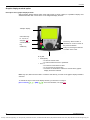
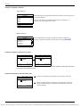
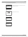
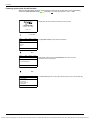
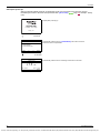
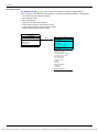
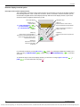
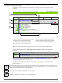
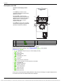

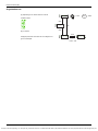
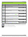

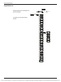
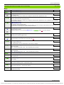
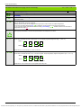
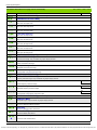
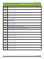
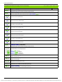
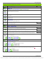

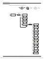

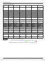
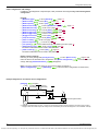
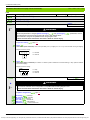
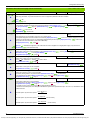
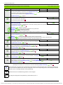
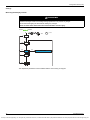
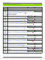
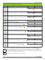
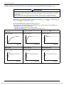
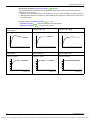
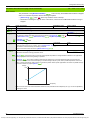
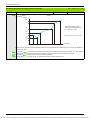
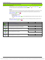
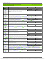
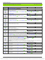
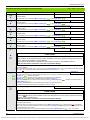
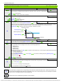
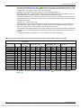
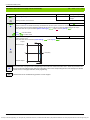

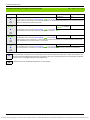
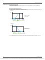

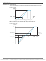
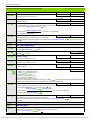
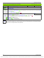
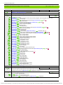
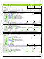
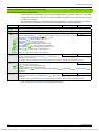
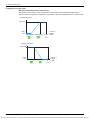
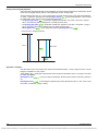
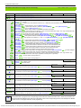
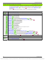
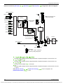
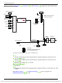
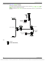
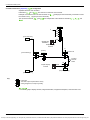
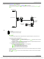
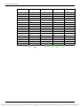
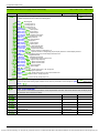
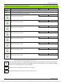
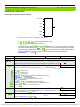
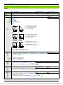
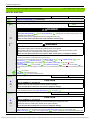
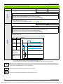
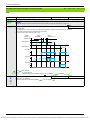
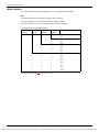
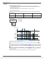
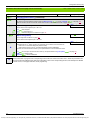
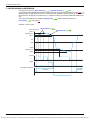
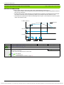
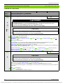
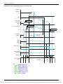
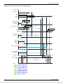
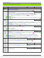
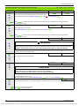
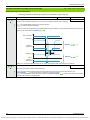
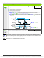
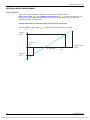
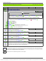
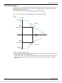
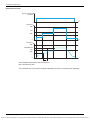
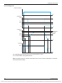
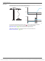
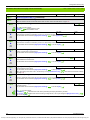
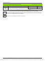
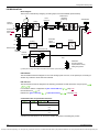
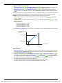
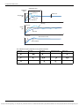
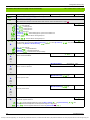
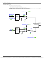
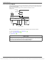
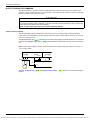
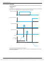
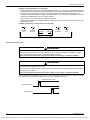
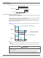
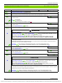
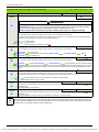
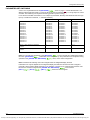
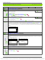
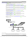
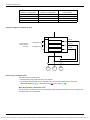
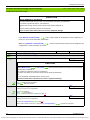
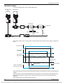
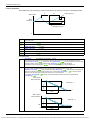
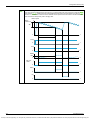
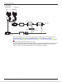
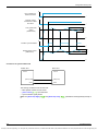
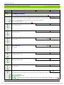
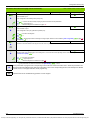
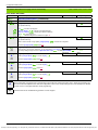
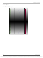
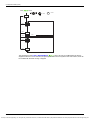
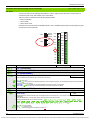
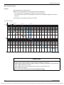
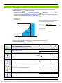
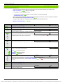
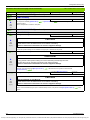
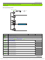
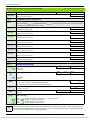
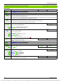
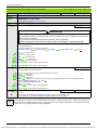

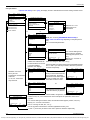
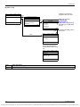
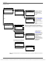

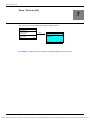
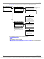

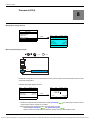
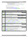
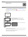


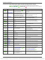
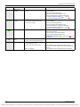
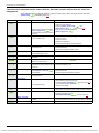
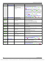


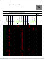
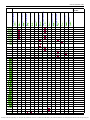
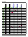
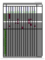
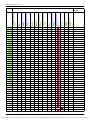
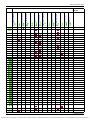
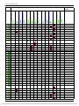
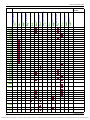
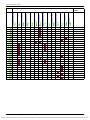


![[1.7 APPLICATION FUNCT.] (FUn](http://vs1.manualzilla.com/store/data/005865551_1-ec59525967aac13e1fcb9d41d71413ed-150x150.png)