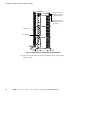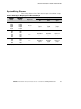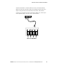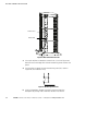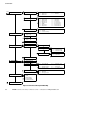
1
Powerware® 9170+ UPS
3–18 kVA
User’s Guide
Requesting a Declaration of Conformity
Units that are labeled with a CE mark comply with the following harmonized standards and EU directives:
S
Harmonized Standards: EN 50091-1-1 and EN 50091-2; IEC 60950 Third Edition
S
EU Directives:
73/23/EEC, Council Directive on equipment designed for use within certain voltage limits
93/68/EEC, Amending Directive 73/23/EEC
89/336/EEC, Council Directive relating to electromagnetic compatibility
92/31/EEC, Amending Directive 89/336/EEC relating to EMC
The EC Declaration of Conformity is available upon request for products with a CE mark. For copies of the EC
Declaration of Conformity, contact:
Eaton Power Quality Oy
Koskelontie 13
FIN-02920 Espoo
Finland
Phone: +358-9-452 661
Fax: +358-9-452 665 68
Powerware, LanSafe, and FERRUPS are registered trademarks and ConnectUPS and BestDock are trademarks of
Eaton Power Quality Corporation.
Torx is a registered trademark of Textron, Inc.
ECopyright 2000–2006 Eaton Corporation, Raleigh, NC, USA. All rights reserved. No part of this document may be
reproduced in any way without the express written approval of Eaton Corporation.
Class A EMC Statements
FCC Part 15
NOTE This equipment has been tested and found to comply with the limits for a Class A digital device, pursuant to
part 15 of the FCC Rules. These limits are designed to provide reasonable protection against harmful interference
when the equipment is operated in a commercial environment. This equipment generates, uses, and can radiate
radio frequency energy and, if not installed and used in accordance with the instruction manual, may cause harmful
interference to radio communications. Operation of this equipment in a residential area is likely to cause harmful
interference in which case the user will be required to correct the interference at his own expense.
ICES-003
This Class A Interference Causing Equipment meets all requirements of the Canadian Interference Causing
Equipment Regulations ICES-003.
Cet appareil numérique de la classe A respecte toutes les exigences du Reglement sur le matériel brouilleur du
Canada.
EN 50091-2
Some configurations are classified under EN 50091-2 as “Class-A UPS for Unrestricted Sales Distribution.” For
these configurations, the following applies:
WARNING This is a Class A-UPS Product. In a domestic environment, this product may cause radio interference, in
which case, the user may be required to take additional measures.
VCCI Notice
Special Symbols
The following are examples of symbols used on the UPS or accessories to alert you to important
information:
RISK OF ELECTRIC SHOCK - Indicates that a risk of electric shock is present and the
associated warning should be observed.
CAUTION: REFER TO OPERATOR’S MANUAL - Refer to your operator’s manual for
additional information, such as important operating and maintenance
instructions.
This symbol indicates that you should not discard the UPS or the UPS batteries
in the trash. This product contains sealed, lead-acid batteries and must be
disposed of properly. For more information, contact your local recycling/reuse or
hazardous waste center.
This symbol indicates that you should not discard waste electrical or electronic
equipment (WEEE) in the trash. For proper disposal, contact your local
recycling/reuse or hazardous waste center.
Table of Contents
1
Introduction . . . . . . . . . . . . . . . . . . . . . . . . . . . . . . . . . . . . . . . . . . . . . . . . . . . . . . . .
1
Safety Warnings . . . . . . . . . . . . . . . . . . . . . . . . . . . . . . . . . . . . . . . . . . . . . . . . . . . . . . . . . . . . . . . . . . . . .
Physical Features . . . . . . . . . . . . . . . . . . . . . . . . . . . . . . . . . . . . . . . . . . . . . . . . . . . . . . . . . . . . . . . . . . . .
2
5
Installation Setup . . . . . . . . . . . . . . . . . . . . . . . . . . . . . . . . . . . . . . . . . . . . . . . . . . .
9
Equipment Clearances . . . . . . . . . . . . . . . . . . . . . . . . . . . . . . . . . . . . . . . . . . . . . . . . . . . . . . . . . . . . . . . . .
Location Requirements . . . . . . . . . . . . . . . . . . . . . . . . . . . . . . . . . . . . . . . . . . . . . . . . . . . . . . . . . . . . . . . .
UPS Setup . . . . . . . . . . . . . . . . . . . . . . . . . . . . . . . . . . . . . . . . . . . . . . . . . . . . . . . . . . . . . . . . . . . . . . . . .
Three- and Six-Slot Cabinets . . . . . . . . . . . . . . . . . . . . . . . . . . . . . . . . . . . . . . . . . . . . . . . . . . . . . . . . . .
Nine- and Twelve-Slot Cabinets . . . . . . . . . . . . . . . . . . . . . . . . . . . . . . . . . . . . . . . . . . . . . . . . . . . . . . .
Caster Cart Installation (Three- and Six-Slot Cabinets) . . . . . . . . . . . . . . . . . . . . . . . . . . . . . . . . . . . . . . . . . .
Stabilizer Bracket Installation (Twelve-Slot Cabinet Only) . . . . . . . . . . . . . . . . . . . . . . . . . . . . . . . . . . . . . . . .
Rack-Mount Installation (Three- and Six-Slot Cabinets) . . . . . . . . . . . . . . . . . . . . . . . . . . . . . . . . . . . . . . . . . .
Floor Anchor Kit Installation . . . . . . . . . . . . . . . . . . . . . . . . . . . . . . . . . . . . . . . . . . . . . . . . . . . . . . . . . . . . .
Moving the Cabinets . . . . . . . . . . . . . . . . . . . . . . . . . . . . . . . . . . . . . . . . . . . . . . . . . . . . . . . . . . . . . . . . . .
9
10
10
10
11
12
13
14
16
17
UPS with Bypass Electrical Installation . . . . . . . . . . . . . . . . . . . . . . . . . . . . . . . . . .
19
Input Current Ratings . . . . . . . . . . . . . . . . . . . . . . . . . . . . . . . . . . . . . . . . . . . . . . . . . . . . . . . . . . . . . . . . . .
Bypass Switches . . . . . . . . . . . . . . . . . . . . . . . . . . . . . . . . . . . . . . . . . . . . . . . . . . . . . . . . . . . . . . . . . . . . .
UPS Installation with an External Bypass Switch . . . . . . . . . . . . . . . . . . . . . . . . . . . . . . . . . . . . . . . . . . . . . .
System Wiring Diagrams . . . . . . . . . . . . . . . . . . . . . . . . . . . . . . . . . . . . . . . . . . . . . . . . . . . . . . . . . . . . . . .
21
22
25
33
UPS Electrical Installation . . . . . . . . . . . . . . . . . . . . . . . . . . . . . . . . . . . . . . . . . . . .
39
Input Current Ratings . . . . . . . . . . . . . . . . . . . . . . . . . . . . . . . . . . . . . . . . . . . . . . . . . . . . . . . . . . . . . . . . . .
UPS Electrical Installation . . . . . . . . . . . . . . . . . . . . . . . . . . . . . . . . . . . . . . . . . . . . . . . . . . . . . . . . . . . . . .
System Wiring Diagrams . . . . . . . . . . . . . . . . . . . . . . . . . . . . . . . . . . . . . . . . . . . . . . . . . . . . . . . . . . . . . . .
40
42
48
Isolated Output Wiring Diagrams . . . . . . . . . . . . . . . . . . . . . . . . . . . . . . . . . . . . . . .
53
Neutral-to-Ground Bonding for Isolated Output . . . . . . . . . . . . . . . . . . . . . . . . . . . . . . . . . . . . . . . . . . . . . . .
System Wiring Diagrams . . . . . . . . . . . . . . . . . . . . . . . . . . . . . . . . . . . . . . . . . . . . . . . . . . . . . . . . . . . . . . .
54
56
6
Battery Cabinet Installation . . . . . . . . . . . . . . . . . . . . . . . . . . . . . . . . . . . . . . . . . . . .
61
7
UPS Startup . . . . . . . . . . . . . . . . . . . . . . . . . . . . . . . . . . . . . . . . . . . . . . . . . . . . . . . .
67
Power and Battery Module Installation . . . . . . . . . . . . . . . . . . . . . . . . . . . . . . . . . . . . . . . . . . . . . . . . . . . . .
Startup for Plug-Receptacle Units . . . . . . . . . . . . . . . . . . . . . . . . . . . . . . . . . . . . . . . . . . . . . . . . . . . . . . . . .
68
69
2
3
4
5
EATON Powerware® 9170+ UPS (3–18 kVA) User’s Guide S 164201393 Rev C www.powerware.com
i
TABLE OF CONTENTS
Startup for Hardwired Units . . . . . . . . . . . . . . . . . . . . . . . . . . . . . . . . . . . . . . . . . . . . . . . . . . . . . . . . . . . . .
Initial Startup Parameters . . . . . . . . . . . . . . . . . . . . . . . . . . . . . . . . . . . . . . . . . . . . . . . . . . . . . . . . . . . . . .
72
75
Operation . . . . . . . . . . . . . . . . . . . . . . . . . . . . . . . . . . . . . . . . . . . . . . . . . . . . . . . . . .
79
Turning the UPS On . . . . . . . . . . . . . . . . . . . . . . . . . . . . . . . . . . . . . . . . . . . . . . . . . . . . . . . . . . . . . . . . . . .
Removing Input Power . . . . . . . . . . . . . . . . . . . . . . . . . . . . . . . . . . . . . . . . . . . . . . . . . . . . . . . . . . . . . . . . .
Front Panel Display . . . . . . . . . . . . . . . . . . . . . . . . . . . . . . . . . . . . . . . . . . . . . . . . . . . . . . . . . . . . . . . . . . .
Using the Front Panel Display . . . . . . . . . . . . . . . . . . . . . . . . . . . . . . . . . . . . . . . . . . . . . . . . . . . . . . . . . . . .
Parameters . . . . . . . . . . . . . . . . . . . . . . . . . . . . . . . . . . . . . . . . . . . . . . . . . . . . . . . . . . . . . . . . . . . . . . . . .
Changing Parameter Settings . . . . . . . . . . . . . . . . . . . . . . . . . . . . . . . . . . . . . . . . . . . . . . . . . . . . . . . . . . . .
Reading the Powerware 9170+ System Logs . . . . . . . . . . . . . . . . . . . . . . . . . . . . . . . . . . . . . . . . . . . . . . . . .
Inverter Log . . . . . . . . . . . . . . . . . . . . . . . . . . . . . . . . . . . . . . . . . . . . . . . . . . . . . . . . . . . . . . . . . . . . . .
Alarm Log . . . . . . . . . . . . . . . . . . . . . . . . . . . . . . . . . . . . . . . . . . . . . . . . . . . . . . . . . . . . . . . . . . . . . . .
Battery Test . . . . . . . . . . . . . . . . . . . . . . . . . . . . . . . . . . . . . . . . . . . . . . . . . . . . . . . . . . . . . . . . . . . . . . . .
Menu Map . . . . . . . . . . . . . . . . . . . . . . . . . . . . . . . . . . . . . . . . . . . . . . . . . . . . . . . . . . . . . . . . . . . . . . . . .
81
81
82
83
85
85
86
86
87
88
89
Communication . . . . . . . . . . . . . . . . . . . . . . . . . . . . . . . . . . . . . . . . . . . . . . . . . . . . .
91
Powerware LanSafe Power Management Software . . . . . . . . . . . . . . . . . . . . . . . . . . . . . . . . . . . . . . . . . . . .
Optional Interface Kits . . . . . . . . . . . . . . . . . . . . . . . . . . . . . . . . . . . . . . . . . . . . . . . . . . . . . . . . . . . . . . . . .
Communication Slots . . . . . . . . . . . . . . . . . . . . . . . . . . . . . . . . . . . . . . . . . . . . . . . . . . . . . . . . . . . . . . . . . .
ConnectUPS Web/SNMP Card (BD Model) . . . . . . . . . . . . . . . . . . . . . . . . . . . . . . . . . . . . . . . . . . . . . . . .
Relay Interface Card (BestDock Model) . . . . . . . . . . . . . . . . . . . . . . . . . . . . . . . . . . . . . . . . . . . . . . . . . .
Dedicated Input Signals . . . . . . . . . . . . . . . . . . . . . . . . . . . . . . . . . . . . . . . . . . . . . . . . . . . . . . . . . . . . . . . .
DB-9 Communication Port . . . . . . . . . . . . . . . . . . . . . . . . . . . . . . . . . . . . . . . . . . . . . . . . . . . . . . . . . . . . . .
91
91
92
92
92
92
94
10 Maintenance . . . . . . . . . . . . . . . . . . . . . . . . . . . . . . . . . . . . . . . . . . . . . . . . . . . . . . .
95
Routine Maintenance . . . . . . . . . . . . . . . . . . . . . . . . . . . . . . . . . . . . . . . . . . . . . . . . . . . . . . . . . . . . . . . . .
Storage Temperature . . . . . . . . . . . . . . . . . . . . . . . . . . . . . . . . . . . . . . . . . . . . . . . . . . . . . . . . . . . . . . . . . .
External Bypass Switch (Make-Before-Break Only) Operation . . . . . . . . . . . . . . . . . . . . . . . . . . . . . . . . . . . . .
Battery Replacement . . . . . . . . . . . . . . . . . . . . . . . . . . . . . . . . . . . . . . . . . . . . . . . . . . . . . . . . . . . . . . . . . .
Power Module Replacement . . . . . . . . . . . . . . . . . . . . . . . . . . . . . . . . . . . . . . . . . . . . . . . . . . . . . . . . . . . . .
95
96
96
96
97
11 Specifications . . . . . . . . . . . . . . . . . . . . . . . . . . . . . . . . . . . . . . . . . . . . . . . . . . . . . .
99
12 Troubleshooting . . . . . . . . . . . . . . . . . . . . . . . . . . . . . . . . . . . . . . . . . . . . . . . . . . . . .
107
Alarms . . . . . . . . . . . . . . . . . . . . . . . . . . . . . . . . . . . . . . . . . . . . . . . . . . . . . . . . . . . . . . . . . . . . . . . . . . . .
Service and Support . . . . . . . . . . . . . . . . . . . . . . . . . . . . . . . . . . . . . . . . . . . . . . . . . . . . . . . . . . . . . . . . . .
109
113
13 Warranty . . . . . . . . . . . . . . . . . . . . . . . . . . . . . . . . . . . . . . . . . . . . . . . . . . . . . . . . . .
115
Two-Year Limited Warranty (US and Canada) . . . . . . . . . . . . . . . . . . . . . . . . . . . . . . . . . . . . . . . . . . . . . . . . .
Ten-Year Pro-Rated Limited Warranty (US and Canada) . . . . . . . . . . . . . . . . . . . . . . . . . . . . . . . . . . . . . . . . .
Load Protection Guarantee (US and Canada) . . . . . . . . . . . . . . . . . . . . . . . . . . . . . . . . . . . . . . . . . . . . . . . . .
115
117
119
8
9
ii
EATON Powerware® 9170+ UPS (3–18 kVA) User’s Guide S 164201393 Rev C www.powerware.com
Chapter 1
Introduction
The Powerware® 9170+ uninterruptible power system (UPS) is a modular
UPS that contains battery modules and power control modules (referred
to as power modules). These modules plug into a rack cabinet structure
containing additional control, communication, and display functions that
enable integrated control of all power modules. The UPS is housed in a
single cabinet, with extra battery capacity housed in auxiliary battery
cabinets.
The pluggable power modules can be removed and replaced
(hot-swapped) without powering the UPS down if the UPS has sufficient
redundant capacity. Battery modules may also be hot-swapped for
maintenance. Power control circuitry in the cabinet senses problems in
power modules, and automatically transfers control and load to the
remaining power modules.
All power modules share the load requirements equally. For example,
three power modules are capable of supplying a total of 9 kVA. If a load
requires only 4.5 kVA, each power module supplies 1.5 kVA to the
output. If one power module is removed or for some reason fails, each
of the two remaining power modules would supply half of the load, or
2.25 kVA. In other words, redundancy exists when the load can be
supplied by less than all of the installed power modules.
The UPS can be configured with up to seven power and/or optional
battery charger modules; its output is limited such that an excess
number of power modules allow the failure of one or more modules
without causing the UPS to lose any functionality.
To permit UPS removal from the power path while maintaining power to
the loads, an external bypass switch is required. This switch is optional
but recommended for system serviceability.
EATON Powerware® 9170+ UPS (3–18 kVA) User’s Guide S 164201393 Rev C www.powerware.com
1
INTRODUCTION
Safety Warnings
IMPORTANT SAFETY INSTRUCTIONS
SAVE THESE INSTRUCTIONS
This manual contains important instructions that you should follow during installation and
maintenance of the UPS and batteries. Please read all instructions before operating the
equipment and save this manual for future reference.
CAUTION
S Split-phase power modules (model ASY-0673) have brown labels on the front and
produce two output voltages: 100/100 for 200, 110/110 for 220, 120/120 for 240,
120/120 for 208, or 127/127 for 220 Vac. Universal power modules (model ASY-0674)
have black labels on the front and produce a single output voltage: 200, 208, 220, 230,
or 240 Vac. DO NOT mix the two types of power modules in the same Powerware 9170+
cabinet.
S Do NOT install more than seven power and/or optional battery charger modules in the
system.
S Battery modules to be used in the Powerware 9170+ system are model ASY-0529. Each
battery module weighs 14 kg (30 lb). Use care in lifting and moving battery modules.
S All input and output wiring must be copper and adequate to carrying currents as listed in
Table 16 and Table 17 on pages 100 and 102.
S Torque all bolts holding input and output power conductors to values specified in Table 2
on page 22.
S The user is required to provide power input and output disconnect devices for the UPS.
These must be within sight of the UPS and easily accessible. For a plug-receptacle unit,
the plug serves as the power input disconnect device, which must also be readily
accessible.
2
EATON Powerware® 9170+ UPS (3–18 kVA) User’s Guide S 164201393 Rev C www.powerware.com
INTRODUCTION
Consignes de Sécurité
CONSIGNES DE SÉCURITÉ IMPORTANTES
CONSERVER CES INSTRUCTIONS
Ce manuel comporte des instructions importantes que vous êtes invité à suivre lors de toute
procédure d’installation et de maintenance des batteries et de l’onduleur. Veuillez consulter
entièrement ces instructions avant de faire fonctionner l’équipement et conserver ce manuel
afin de pouvoir vous y reporter ultérieurement.
ATTENTION!
S Les blocs de puissance à phase auxiliaire (modèle ASY-0673) sont dotés d’étiquettes
marron sur le dessus et produisent deux tensions de sortie : 100/100 pour 200, 110/110
pour 220, 120/120 pour 240, 120/120 pour 208, ou 127/127 pour 220 Vca. Les blocs de
puissance universels (modèle ASY-0674) sont dotés d’étiquettes noires sur le dessus et
produisent une seule tension de sortie : 200, 208, 220, 230 ou 240 Vca. NE mélangez
PAS les deux types de blocs de puissance dans le même module d’unité d’alimentation.
S N’installez PAS plus de sept chargeurs de batteries optionnels et/ou de puissance dans
le système.
S Les modules de batterie à utiliser dans le système Powerware 9170+ correspondent au
modèle ASY-0529. Chaque module de batterie pèse 14 kg (30 lb). Levez ou déplacez les
modules de batterie avec soin.
S Tous les câblages d’entrée et de sortie doivent être en cuivre et doivent prendre en
charge les courants répertoriés dans les Table 16 et Table 17 des pages 100 et 102.
S Couplez tous les boulons en maintenant les conducteurs de sortie sur les valeurs
indiquées dans le Table 2 à la page 22.
S L’utilisateur doit fournir des appareils de déconnexion de l’alimentation en entrée et en
sortie pour l’onduleur. Ceux-ci doivent se trouver dans le périmètre de l’onduleur et être
faciles d’accès. En ce qui concerne l’unité de prise, la prise sert d’appareil de
déconnexion de l’alimentation en entrée, laquelle doit également être facile d’accès.
EATON Powerware® 9170+ UPS (3–18 kVA) User’s Guide S 164201393 Rev C www.powerware.com
3
INTRODUCTION
Advertencias de Seguridad
INSTRUCCIONES DE SEGURIDAD IMPORTANTES
GUARDE ESTAS INSTRUCCIONES
Este manual contiene instrucciones importantes que debe seguir durante la instalación y el
mantenimiento del SIE y de las baterías. Por favor, lea todas las instrucciones antes de
poner en funcionamiento el equipo y guarde este manual para referencia en el futuro.
PRECAUCIÓN
S Los módulos de potencia de fase dividida (modelo ASY-0673) portan etiquetas de color
café en la parte delantera y producen dos voltajes de salida: 100/100 para 200, 110/110
para 220, 120/120 para 240, 120/120 para 208 ó 127/127 para 220 Vca. Los módulos de
potencia universal (modelo ASY-0674) portan etiquetas negras en la parte delantera y
producen un solo voltaje de salida: 200, 208, 220, 230 ó 240 Vca. NO combine los dos
tipos de módulos de potencia en el mismo gabinete de la Unidad de distribución de
alimentación.
S NO instale en los módulos de potencia del sistema más de siete módulos de potencia
y/o de cargadores opcionales de baterías.
S Los módulos de baterías a utilizarse en el sistema Powerware 9170+ son del modelo
ASY-0529. Cada módulo de batería pesa 14 kg (30 lb). Levante y mueva con cuidado los
módulos de baterías.
S Todo el cableado de entrada y de salida debe ser de cobre y del tipo adecuado para
transportar las corrientes detalladas en la Table 16 y en la Table 17, en las páginas
100 y 102.
S Apriete todos los pernos que sostengan los conductos de alimentación de entrada y de
salida según los valores de torsión especificados en la Table 2, en la página 22.
S Se le solicita al usuario suministrar dispositivos de desconexión de entrada y salida de
alimentación para el SIE. Éstos deben estar a la vista del SIE y ser de fácil acceso. Para
una unidad con receptáculo de conexión, el conector funge como dispositivo de
desconexión de entrada de alimentación, el cual también debe estar fácilmente
accesible.
4
EATON Powerware® 9170+ UPS (3–18 kVA) User’s Guide S 164201393 Rev C www.powerware.com
INTRODUCTION
Physical Features
The Powerware 9170+ UPS is available in four cabinet sizes. Figure 1
through Figure 6 show the 3-slot and 9-slot configurations and identify
basic Powerware 9170+ system features. Six-slot and 12-slot cabinets
are also available; external battery cabinets are available in 6-, 9-, and
12-slot sizes.
Front Panel
Display
Front Cover
Figure 1. Three-Slot Cabinet (Front View)
Communication
Slots
DB-9
Communication
Port
Power Outlets
(optional)
Input Power
Cable (optional)
Figure 2. Three-Slot Cabinet (Rear View)
EATON Powerware® 9170+ UPS (3–18 kVA) User’s Guide S 164201393 Rev C www.powerware.com
5
INTRODUCTION
Front Panel Display
Front Cover
Cabinet Base
Figure 3. Nine-Slot Cabinet (Front View)
6
EATON Powerware® 9170+ UPS (3–18 kVA) User’s Guide S 164201393 Rev C www.powerware.com
INTRODUCTION
DB-9 Communication Port
Communication
Slots
Wiring Access
Power Outlets
(optional)
Input Power
Cable (optional)
Figure 4. Nine-Slot Cabinet (Rear View)
Handle/Latch
Release
Handle
Thumbscrew
Insertion/Extraction
Cams
Figure 5. Power Module (ASY-0673 and ASY-0674)
Secondary Stop
Release
Latch Release
Figure 6. Battery Module (ASY-0529)
EATON Powerware® 9170+ UPS (3–18 kVA) User’s Guide S 164201393 Rev C www.powerware.com
7
INTRODUCTION
8
EATON Powerware® 9170+ UPS (3–18 kVA) User’s Guide S 164201393 Rev C www.powerware.com
Chapter 2
Installation Setup
This chapter explains how to set up and install the Powerware 9170+
cabinets:
S Setup, including clearances and location requirements
S Caster cart installation (for 3- and 6-slot cabinets)
S Stabilizer bracket installation (for 12-slot cabinets with non-isolated
output)
S Rack-mount installation (for 3- and 6-slot cabinets)
S Floor anchor kit installation
S Moving the cabinets
Equipment Clearances
All cabinet sizes require the following clearances to allow for servicing
and adequate ventilation:
S Sides: 15.2 cm (6”)
S Top and back: 30.5 cm (12”)
S Front: 91.5 cm (36”)
If flexible conduit connects the UPS to the service input and load
distribution panels, you may be able to gain access for servicing by
moving the UPS. If this is the case, you must still leave 30.5 cm (12”)
clearance at the back and 15.2 cm (6”) at the sides of the UPS for
ventilation.
NOTE Do not block the ventilation holes on each side and the back of the cabinet.
Nine- and 12-slot external battery cabinets may be installed with bases
tight against the UPS cabinet base and against each other. Six-slot
cabinets require 15.2 cm (6”) of separation.
EATON Powerware® 9170+ UPS (3–18 kVA) User’s Guide S 164201393 Rev C www.powerware.com
9
INSTALLATION SETUP
Location Requirements
Install the Powerware 9170+ UPS as close as possible to the equipment
or the load distribution panel it will protect. If this distance is more than
7.6m (25 ft), transient noise can reappear in the electrical distribution
system.
If a separate external battery cabinet is installed, the battery cabinets
must be adjacent to the Powerware 9170+ UPS. If the batteries will be
farther from the cabinet than the standard cables allow, contact your
service representative or your local distributor for assistance.
UPS Setup
The Powerware 9170+ UPS is shipped in a carton on a shipping pallet.
Power and battery modules are shipped in separate boxes on another
pallet. Three-slot cabinets and modules are shipped on one pallet. Refer
to the unpacking instruction sheet (LTS-1724) packed inside the UPS
shipping carton.
NOTE Verify that all Powerware 9170 + UPS power modules are the proper type for the UPS
cabinet: Split-phase power modules have brown labels; universal (single-phase) power
modules have black labels. Do not mix brown and black modules in the same UPS cabinet.
Three- and Six-Slot Cabinets
NOTE Do not attempt to lift the cabinet by the module shelves or other convenient edges
or covers.
To set up 3- or 6-slot cabinets:
10
1.
Place the cabinet in its intended operating location.
2.
If an optional caster cart is included for cabinet mobility, see
“Caster Cart Installation (Three- and Six-Slot Cabinets)” on page 12
to mount the cabinet on the cart and stabilize it using the cart foot
pads.
3.
Cut the lifting straps or slip them off the cabinet base tabs.
4.
If an optional floor anchor kit is included for extra stability, see
”Floor Anchor Kit Installation” on page 16 to install the floor anchor
brackets.
EATON Powerware® 9170+ UPS (3–18 kVA) User’s Guide S 164201393 Rev C www.powerware.com
INSTALLATION SETUP
5.
If installing the 3- or 6-slot cabinet in a rack, see ”Rack-Mount
Installation (Three- and Six-Slot Cabinets)” on page 14 to install the
cabinet in the rack.
6.
If you are installing an external battery cabinet, continue to “Battery
Cabinet Installation” on page 61.
If you do not have an external battery cabinet, continue to “UPS
Startup” on page 67 for plug-receptacle units. For hardwired units,
continue to “UPS with Bypass Electrical Installation” on page 19 or
“UPS Electrical Installation” on page 39.
Nine- and Twelve-Slot Cabinets
CAUTION
Do NOT lower the casters or attempt to move the cabinet with the power or battery modules
installed.
To set up 9- or 12-slot cabinets:
NOTE If you are installing a 12-slot Powerware 9170 + UPS with non-isolated output, do
not follow this procedure. Proceed to “Stabilizer Bracket Installation (Twelve-Slot Cabinet
Only)” on page 13.
1.
Lower the four cabinet casters (one at each corner of the cabinet
base) by using a 1/2” hex-style socket wrench to turn each bolt
clockwise.
2.
With all casters fully extended, carefully roll the cabinet down the
ramp to its intended operating location.
3.
Stabilize the cabinet in its operating location by turning the four
caster bolts counter-clockwise until the cabinet rests on the floor.
Place a plastic cap into each bolt access hole.
NOTE If the floor is uneven and the cabinet is tilted or unstable, you may need to place a
thin steel plate under a corner. Do not use the caster bolts to level the cabinet.
4.
If an optional floor anchor kit is included for extra stability, see
”Floor Anchor Kit Installation” on page 16 to install the floor anchor
brackets.
EATON Powerware® 9170+ UPS (3–18 kVA) User’s Guide S 164201393 Rev C www.powerware.com
11
INSTALLATION SETUP
5.
If installing the 9- or 12-slot cabinet in a rack, follow the installation
instructions with the 9- and 12-slot rack-mount kit.
6.
If you are installing an external battery cabinet, continue to “Battery
Cabinet Installation” on page 61.
If you do not have an external battery cabinet, continue to “UPS
Startup” on page 67 for plug-receptacle units. For hardwired units,
continue to “UPS with Bypass Electrical Installation” on page 19 or
“UPS Electrical Installation” on page 39.
Caster Cart Installation (Three- and Six-Slot Cabinets)
An optional caster cart (ASY-0527) is available for 3- and 6-slot cabinets
for increased mobility of the UPS (see Figure 7).
NOTE The UPS cabinet is heavy (see page 106). This procedure requires two people to lift
and position the cabinet onto the caster cart. Lift the cabinet using four lifting straps shipped
with the cabinet; do not attempt to lift the cabinet by the module shelves or other convenient
edges or covers.
Caster Cart
Figure 7. Three-Slot Cabinet Being Lowered onto Caster Cart
12
EATON Powerware® 9170+ UPS (3–18 kVA) User’s Guide S 164201393 Rev C www.powerware.com
INSTALLATION SETUP
To install the caster cart:
1.
Place the caster cart (shipped separately from the UPS cabinet)
under the cabinet before installing power and battery modules and
before making connections to the intended power source.
The cart requires no bolts or other hardware to fasten it to the UPS
cabinet. It is shaped to fit securely under the cabinet, ensuring
proper alignment after placing the cabinet on the cart.
2.
Four foot pads under the cart keep the cart from rolling when it is in
its intended location. Turn each threaded foot to lower it to the
floor. When the foot is tight against the floor, turn the locknut on
the threaded foot up tight against the bottom of the cart to keep the
foot from rotating.
3.
If leveling of the UPS is required, use the foot pads to raise a side
or corner before locking them with their locknuts.
Stabilizer Bracket Installation (Twelve-Slot Cabinet Only)
The 12-slot Powerware 9170+ UPS cabinet with non-isolated output is
shipped with two stabilizer brackets. These brackets must be attached
to the wall or the floor behind the UPS cabinet. Under all module-loading
conditions, they act as a protective stop to prevent the cabinet from
falling forward if it is unintentionally pushed away from the wall.
Each bracket has holes that enable it to be attached by screws to either
the wall or the floor (or both) behind the intended cabinet installation
(see Figure 8). The stabilizer brackets are not attached to the cabinet
base itself.
To install the stabilizer brackets:
1.
Select the location for the brackets, approximately 30–41 cm
(12–16”) apart, at the floor/wall intersection behind the intended
cabinet location.
2.
Using the proper type of customer-supplied screws for the intended
mounting surface, attach each bracket as shown in Figure 8. All
screws must be driven into structural material such as wall studs.
3.
Roll the UPS cabinet to its intended location. Position the rear
section of the cabinet base under the open ends of the stabilizer
brackets as far as the cabinet will go.
EATON Powerware® 9170+ UPS (3–18 kVA) User’s Guide S 164201393 Rev C www.powerware.com
13
INSTALLATION SETUP
4.
Turn all four caster bolts counter-clockwise until the cabinet rests
on the floor. Place a plastic cap into each bolt access hole.
NOTE If the floor is uneven and the cabinet is tilted or unstable, you may need to place a
thin steel plate under a corner. Do not use the caster bolts to level the cabinet.
Stabilizer Bracket
Figure 8. Stabilizer Bracket Installation
Rack-Mount Installation (Three- and Six-Slot Cabinets)
NOTE For 9- and 12-slot cabinets, follow the installation instructions with the 9- and
12-slot rack-mount kit.
NOTE The UPS cabinet is heavy (see page 106). This procedure requires two people to lift
and position the cabinet into the equipment rack. Install the cabinet in the rack before
installing power and battery modules and before making connections to the intended power
source.
The 3- and 6-slot UPS cabinets may be installed in an EIA-standard
48.3 cm (19”) equipment rack. An optional rack-mounting kit (ASY-0547),
containing brackets and required hardware, is available.
For each 3-slot section, use the following mounting procedure to convert
the UPS cabinet and install it in the equipment rack:
14
1.
Remove the four screws (two on either side) securing the top cover
of the UPS cabinet. Carefully lift the cover straight up and off to
avoid stressing the front panel display. Set the cover aside.
2.
Remove the two cabinet side covers (four covers in 6-slot cabinets)
by lifting the top edge. No other hardware must be detached. Store
or discard the side covers.
EATON Powerware® 9170+ UPS (3–18 kVA) User’s Guide S 164201393 Rev C www.powerware.com
INSTALLATION SETUP
3.
Carefully replace the UPS cabinet top cover and secure with the
four screws removed in Step 1. Position the cover lip to fit behind
the front panel display.
4.
Install three metal clip nuts onto each side flange (six clip nuts on
6-slot cabinets) along the front of the UPS cabinet (see Figure 9).
Tab Slots
Metal Clip Nuts
Figure 9. Metal Clip Nut and Tab Slot Locations
5.
Install a rack-mount ear (two for 6-slot cabinets) on each side of the
UPS cabinet (see Figure 10).
Insert the two offset tabs on the rear edge of the ear into the
matching tab slots on the cabinet side frame (see Figure 9). Pivot
the ear forward until it is flush against the UPS cabinet side frame.
Using three 1/4-20×1/2” Phillips-head bolts, screw the bolts into
the metal clip nuts installed in Step 4.
Rack-Mount Ear
Figure 10. Rack-Mount Ear Installed
6.
Select the position for the UPS in the equipment rack.
EATON Powerware® 9170+ UPS (3–18 kVA) User’s Guide S 164201393 Rev C www.powerware.com
15
INSTALLATION SETUP
7.
Install one equipment rail on each side of the rack using four
10-32×1/2” flat-head screws per rail. Select the proper holes in the
rail that position the UPS at the desired location in the rack (see
Figure 11).
Equipment Rail
Figure 11. Rails Holding UPS
8.
With one person lifting each side of the UPS cabinet, position the
cabinet onto the two equipment rails.
Carefully slide the UPS into the equipment rack until the rack-mount
ears of the cabinet are flush with the front vertical rails of the rack.
Verify that the holes in the ears align with the holes in the rack.
9.
Secure the UPS in the rack using eight 10-32×1/2” Torx® screws
(16 for 6-slot cabinets) or other appropriate customer-specified
screws.
Floor Anchor Kit Installation
An optional floor anchor kit (ASY-0548) is available for all sizes of the
Powerware 9170+ UPS. The kit helps to stabilize the UPS or battery
cabinet in the event of accidental bumps or small floor movements. Any
testing to specific seismic requirements is the responsibility of the
customer.
The floor anchor brackets, shipped separately from the UPS and battery
cabinet, should be attached inside the lower front and rear edges of the
cabinet before installing power and battery modules and before making
connections to the intended power source.
16
EATON Powerware® 9170+ UPS (3–18 kVA) User’s Guide S 164201393 Rev C www.powerware.com
INSTALLATION SETUP
Use mounting hardware supplied with the floor anchor kit to attach the
brackets to the UPS or external battery cabinet (see Figure 12). The
customer is responsible for specifying and supplying floor mounting
bolts.
Mounting Centers for 8 mm (5/16”) Floor Bolts
Dimension (see Figure 12)
Measurement
A
36.8 cm (14.5”)
B (3- and 6-slot cabinets)
76.8 cm (30.25”)
B (9- and 12-slot cabinets)
87 cm (34.25”)
Floor Anchor
Bracket
B
A
Figure 12. Floor Anchor Brackets Bolted to UPS Cabinet
Moving the Cabinets
CAUTION
Do NOT attempt to raise the cabinet with the power or battery modules installed.
The Powerware 9170+ UPS and the battery cabinet are very heavy with
power and battery modules installed. Before moving the cabinets,
remove the power and battery modules. Move the modules separately
from the cabinets.
The 3- and 6-slot cabinets may be ordered with a caster cart to enable
moving the cabinet. “Caster Cart Installation (Three- and Six-Slot
Cabinets)” on page 12 describes how to set the four foot pads on this
cart to keep the cabinet from rolling when properly positioned.
EATON Powerware® 9170+ UPS (3–18 kVA) User’s Guide S 164201393 Rev C www.powerware.com
17
INSTALLATION SETUP
The 9- and 12-slot cabinets have casters built into the cabinet base. To
raise the cabinet before rolling it on its casters:
1.
Verify that the cabinet contains no power or battery modules.
2.
For 12-slot cabinets with non-isolated output only. Slide the cabinet
base out from under the stabilizer brackets in the rear section of the
cabinet base.
Remove the stabilizer brackets from the floor/wall. Follow the
instructions in “Stabilizer Bracket Installation” on page 13 to
reinstall the stabilizer brackets in the new location.
3.
Locate the four plastic caps covering the caster bolts. They are at
the corners of the cabinet base.
4.
Pry the caps out of the bolt access holes.
5.
Use a 1/2” hex-style socket wrench to turn each of the four bolts
clockwise. Doing so lowers the casters to allow the cabinet to roll
on the casters.
6.
After rolling the cabinet to its intended position, turn all four caster
bolts counter-clockwise until the cabinet rests on the floor. Place a
plastic cap into each bolt access hole.
NOTE If the floor is uneven and the cabinet is tilted or unstable, you may need to place a
thin steel plate under a corner. Do not use the caster bolts to level the cabinet.
7.
18
After properly positioning and leveling the cabinet, insert power and
battery modules into the cabinet as described in “Power and
Battery Module Installation” on page 68.
EATON Powerware® 9170+ UPS (3–18 kVA) User’s Guide S 164201393 Rev C www.powerware.com
Chapter 3
UPS with Bypass Electrical Installation
NOTE If you have a plug-receptacle unit, continue to “Battery Cabinet Installation” on
page 61 for installing optional battery cabinets or to “UPS Startup” on page 67.
WARNING
Only qualified service personnel (such as a licensed electrician) should perform the electrical
installation. Risk of electrical shock.
The Powerware 9170+ UPS input power may be hardwired through
conduit to either a main power source circuit breaker or to an optional
external bypass switch. For hardwired installations, it is recommended
that you install a Powerware bypass switch to enable power transfer
during maintenance or UPS downtime. If a bypass switch is used, both
UPS input and UPS output must be hardwired — through separate
conduits — to the bypass switch, as shown in Figure 13.
EATON Powerware® 9170+ UPS (3–18 kVA) User’s Guide S 164201393 Rev C www.powerware.com
19
UPS WITH BYPASS ELECTRICAL INSTALLATION
External Bypass Switch
Off
Service
Line
Building
Service
Panel
Load
Distribution
Panel
UPS
Off
Service
Line
UPS
Off
Service
Line
UPS
User-Supplied
(if required)
External Batteries
(optional)
Figure 13. Typical Installation with a Bypass Switch
20
EATON Powerware® 9170+ UPS (3–18 kVA) User’s Guide S 164201393 Rev C www.powerware.com
UPS WITH BYPASS ELECTRICAL INSTALLATION
Input Current Ratings
Table 1 contains the required circuit breaker ratings for hardwired
installations. Circuit breaker ratings for units having an input line cord are
determined by the current capacity of the line cord.
Table 1. Required Input Circuit Breaker Sizes (200–240 Vac, 50/60 Hz)
UPS Capacity
Input Circuit Breaker Rating
3 kVA
25A
6 kVA
40A
9 kVA
60A
12 kVA
80A
15 kVA
100A
18 kVA
125A
NOTE If you are installing an optional battery charger module, refer to that user’s guide for
the proper input circuit breaker sizes and ratings.
NOTE To accommodate the feature of easy system expandability, it is recommended that
initial installation of the Powerware 9170 + UPS contains wiring to support the maximum
capacity of the UPS cabinet: 3 kVA for 3-slot cabinets; 9 kVA for 6-slot cabinets; 18 kVA for
9- and 12-slot cabinets.
EATON Powerware® 9170+ UPS (3–18 kVA) User’s Guide S 164201393 Rev C www.powerware.com
21
UPS WITH BYPASS ELECTRICAL INSTALLATION
See Table 2 for recommended conductor sizes to wire the input circuit
breakers.
Table 2. Recommended Wire Sizes
Input Circuit Breaker Size
75°C Copper Wire Size
Conductor Screw Torque
25A
5.3 mm2 (10 AWG)
4.0 Nm (35 lb in)
40A
8.4 mm2 (8 AWG)
4.5 Nm (40 lb in)
60A
21.2 mm2 (4 AWG)
5.1 Nm (45 lb in)
80A
26.7 mm2 (3 AWG)
6.6 Nm (50 lb in)
100A
33.6 mm2 (2 AWG)
6.6 Nm (50 lb in)
125A
42.1 mm2 (1 AWG)
6.6 Nm (50 lb in)
FOR U.S. INSTALLATIONS, READ THIS IMPORTANT NOTE!
This table lists the mm2 and AWG wire size for each circuit breaker size shown on the
wiring diagrams. The minimum recommended circuit breaker sizes for each model and
voltage application are listed on the wiring diagrams.
Conductor sizes shall be no smaller than the 75°C wire size based on the ampacities
given in Table 310–16 of the National Electrical Code, ANSI/NFPA 70-1999, and
article 220. All circuit conductors, including the neutral conductor, must be the same
size (ampacity) wire. Code may require a larger AWG size than shown in this table
because of temperature, number of conductors in the conduit, or long service runs.
Follow local code requirements.
Bypass Switches
Bypass switches are available in two types: Make-Before-Break (MBB)
and Break-Before-Make (BBM).
An MBB switch makes a new connection before it breaks the original
connection. For example, if you turn an MBB switch from UPS to LINE,
the bypass switch connects the load to AC input power before
disconnecting the load from UPS output power. (As noted in Figure 39
on page 57, MBB switches may not be used in certain system
configurations.)
A BBM switch breaks the original connection before it makes a new
one. If you turn a BBM switch from UPS to LINE, the switch
disconnects the load from UPS output power before connecting the load
to AC input power.
The bypass switch has four positions as described in Table 3.
22
EATON Powerware® 9170+ UPS (3–18 kVA) User’s Guide S 164201393 Rev C www.powerware.com
UPS WITH BYPASS ELECTRICAL INSTALLATION
NOTE In the UPS or LINE position, AC input power is still connected to the input terminals
inside the UPS.
Table 3. Bypass Switch Positions
Switch Position
Description
LINE
Connects the load directly to AC input power and disconnects UPS output. AC input power is
still connected to the UPS input.
OFF
Disconnects the load from the UPS output power and AC input power, as well as AC input
power to the UPS input.
UPS
Connects the UPS output to the load.
SERVICE
Like the LINE position, SERVICE connects the load directly to AC input power and disconnects
UPS output. However, because SERVICE also disconnects AC input from the UPS, this is
the appropriate position for UPS maintenance or repair.
To disconnect AC input power during maintenance or service, turn the
bypass switch to the SERVICE position. For MBB switches, you must
press the red button beside the switch before you can change the
switch position.
Table 4 shows the bypass switch models available for the Powerware
9170+ UPS.
Table 4. Bypass Switch Specifications
Bypass Switch Models
BBM
MBB
See Figure 14
Rating,
Continuous
Height
Width
Depth
Mounting Centers
(A)
(B)
(C)
(D)
(E)
Weight
BPE12BBM1A BPE12MBB1A
40A/300 Vac
(CSA)
50A/300 Vac
(UL,TÜV)
53.4 cm
(21.0”)
35.6 cm
(14.0”)
17.2 cm
(6.8”)
28.0 cm
(11.0”)
50.8 cm
(20.0”)
12.3 kg
(27 lb)
BPE14BBM1A BPE14MBB1A
80A/300 Vac
53.4 cm
(21.0”)
35.6 cm
(14.0”)
17.2 cm
(6.8”)
28.0 cm
(11.0”)
50.8 cm
(20.0”)
14.1 kg
(31 lb)
BPE20BBM1A BPE20MBB1A
125A/300 Vac
53.4 cm
(21.0”)
35.6 cm
(14.0”)
17.2 cm
(6.8”)
28.0 cm
(11.0”)
50.8 cm
(20.0”)
15.9 kg
(35 lb)
EATON Powerware® 9170+ UPS (3–18 kVA) User’s Guide S 164201393 Rev C www.powerware.com
23
UPS WITH BYPASS ELECTRICAL INSTALLATION
D
A
E
B
C
Figure 14. Bypass Switch Dimensions
24
EATON Powerware® 9170+ UPS (3–18 kVA) User’s Guide S 164201393 Rev C www.powerware.com
UPS WITH BYPASS ELECTRICAL INSTALLATION
UPS Installation with an External Bypass Switch
WARNING
Only qualified service personnel (such as a licensed electrician) should perform the electrical
installation. Risk of electrical shock.
CAUTION
To prevent electrical shock or damage to the equipment, verify that the Powerware 9170+
UPS is OFF before you remove the entrance panel. The circuit breaker or disconnect switch
must also be off at the AC input service panel. Also, turn OFF the AC disconnect and bypass
switches before you connect any wires to the bypass switch terminal strip.
To install the UPS with an external bypass switch:
1.
Mount the bypass switch within sight of the UPS. If you do not
have a Powerware bypass switch or the fuse box or panel is out of
sight, you must install a separate disconnect switch next to the
UPS.
The bypass switch should be mounted securely to a sturdy surface.
You may need to turn the cabinet 90 degrees (on its side) to enable
operator access to the switch handle.
2.
Remove the six screws in the bypass switch front cover and
remove the cover. Remove any packing material inside the bypass
switch.
3.
Remove knockouts in the bottom of the bypass switch for AC Line
Input, AC to UPS Input, AC from UPS Output, and AC to the UPS
load.
4.
Unscrew and remove the rear cover(s) of the UPS (top cover on 3or 6-slot; top two covers on 9- or 12-slot). See Figure 15.
The entrance panel contains knockout openings for entrance and
exit conduits and for conduit to an optional external battery cabinet.
The entrance panel is located on the top 3-slot section for 3- and
6-slot cabinets; on the second section for 9- and 12-slot cabinets as
shown in Figure 15.
Wiring for optional emergency power-off (EPO) and bypass input
signals passes through the opening at the top back of the cabinet.
Wiring for an optional generator input signal must pass through a
separate opening. Installing this wiring is described in Steps 14
and 15 on page 32.
EATON Powerware® 9170+ UPS (3–18 kVA) User’s Guide S 164201393 Rev C www.powerware.com
25
UPS WITH BYPASS ELECTRICAL INSTALLATION
Wiring Access Hole
for Optional EPO and
Bypass Input Signals
Wiring Access Hole for
an Optional Generator
Input Signal
Entrance Panel
Battery Cable
Figure 15. UPS Power Entrance Panel (Nine-Slot Cabinet Shown)
5.
26
Remove the knockouts in the entrance panel for AC input and AC
output wiring.
EATON Powerware® 9170+ UPS (3–18 kVA) User’s Guide S 164201393 Rev C www.powerware.com
UPS WITH BYPASS ELECTRICAL INSTALLATION
6.
Install the conduit adapters. AC input and AC output conductors
must be run through separate conduits. UPS output circuits must
be installed in dedicated conduit systems and not shared with other
electrical circuits.
Figure 16 shows input and output wiring terminals inside the
Powerware 9170+ UPS cabinet.
3
+DC X3
X2
X1
2
1
N
-DC
Backplane Board
Terminating
Studs
X2
+DC
N
X1
-DC
Figure 16. UPS Input and Output Terminals
EATON Powerware® 9170+ UPS (3–18 kVA) User’s Guide S 164201393 Rev C www.powerware.com
27
UPS WITH BYPASS ELECTRICAL INSTALLATION
7.
Find the terminal strip inside the bypass switch cabinet. Using the
label on the back of the bypass switch access cover and the proper
installation wiring diagram, make the terminal strip connections and
tighten all connections as specified in Table 2 on page 22. Use
copper wire that is the appropriate size for the current draw.
Figure 17 shows a sample label.
Figure 17. Bypass Switch Wiring Label
8.
28
After installing bypass switch wiring, torque the screws holding all
input and output power conductors to the values specified in
Table 2 on page 22.
EATON Powerware® 9170+ UPS (3–18 kVA) User’s Guide S 164201393 Rev C www.powerware.com
UPS WITH BYPASS ELECTRICAL INSTALLATION
9.
Wire the UPS for the proper input voltage as shown in Figure 18.
Split-phase power modules (model ASY-0673, with brown labels on
the front) are capable of supplying two output voltages: 100/100
for 200, 110/110 for 220, 120/120 for 240, 120/120 for 208, or
127/127 for 220 Vac, as selected through the front panel display.
These modules produce two output voltages, typically required in
North America, South America, and Japan.
Universal power modules (model ASY-0674, with black labels on
the front) are capable of supplying a single-phase output voltage:
200, 208, 220, 230, or 240 Vac, as selected through the front panel
display. These modules produce a single output voltage, typically
required in Europe, the Middle East, Asia, and Africa.
CAUTION
Confirm that the UPS is wired for the proper input voltage as shown in Figure 18, and that
the proper power modules (either split-phase or universal) are installed to produce the
desired output voltage. Do not mix the two types of power modules in the same UPS
cabinet.
(a) Split-Phase Power Modules
(b) Universal Power Modules
(3-wire plus ground input) (2 PEN)
100/200, 110/220, 120/208, 120/240, 127/220 Vac
(2-wire plus ground input)
200, 208, 220, 230, and 240 Vac
L2
3
2
1
3
L1
L1
N
L2/N
GND
GND
2
1
Figure 18. UPS Input Wiring
10. For isolated output only. See Chapter 5, “Isolated Output Wiring
Diagrams” on page 53 to complete the wiring for isolated output.
11. See the wiring diagrams beginning on page 33 for output
configurations for various voltages and isolation options. Make UPS
output connections on the backplane board terminating studs.
Compression lugs (supplied in the accessory kit) may be installed
on the proper terminating studs. Wires may also be terminated with
ring terminals, which are attached to the output terminating studs.
EATON Powerware® 9170+ UPS (3–18 kVA) User’s Guide S 164201393 Rev C www.powerware.com
29
UPS WITH BYPASS ELECTRICAL INSTALLATION
Figure 19 and Figure 20 describe output wiring configurations for
various output voltages. You must also set the operating
menu 4 2 4 for the required output voltage as shown in the wiring
configuration drawings.
NOTE For Powerware 9170 + UPS models with low-voltage hardwire output, it is
recommended to divide the total load as equally as possible between X1 and X2, as shown in
Figure 19.
NOTE Failure to balance the loads may cause an overload alarm even if the full capacity of
the UPS has not been reached.
50 or 60 Hz
100/200, 110/220, 127/220, 120/208, or 120/240V Out
Menu 4 2 4 set to 200, 220, 208, or 240, as required.
X2
X
X1
X2
N/-DC
X
X1
X
200, 220
208, or 240
100, 110, 127, or 120
50%
100, 110, 127, or 120
L1 50%
L2
N
Figure 19. Split-Phase Power Modules with Non-Isolated Output
NOTE The factory-default wiring for all high-voltage receptacles in a chassis without a
power cord is 3-wire plus ground input. If you have a universal power module (ASY-0674), all
receptacles MUST be re-wired for a 2-wire plus ground input configuration as shown in
Figure 20.
50 or 60 Hz
200, 208, 220, 230, or 240V Out *
Menu 4 2 4 set to 200, 208, 220, 230, or 240, as required.
X2
N/-DC
X
X1
X
*
L1
L2/N
Figure 20. Universal Power Modules with Non-Isolated Output
30
EATON Powerware® 9170+ UPS (3–18 kVA) User’s Guide S 164201393 Rev C www.powerware.com
UPS WITH BYPASS ELECTRICAL INSTALLATION
12. Unscrew and remove the top rear cover of the cabinet and locate
the terminal block.
13. If the bypass switch is an MBB style, notice the cable routed out of
the left side of the bypass switch cabinet. Connect the red and
black pair of wires (normally open) in this cable to terminals 3 and 4
as shown in Figure 21. (Do not connect the white and black pair of
wires in this cable.)
CAUTION
EPO and external bypass circuits are not isolated from line voltage, and wiring must be
installed according to local codes using conduit or suitable primary supply cables.
The Generator On signal is isolated from line voltage and can be
treated as NEC Class 2 wiring.
Use 14–20 AWG, 600V wire (UL) or 14–26 AWG, 300V wire (CSA)
for all input control signals.
Generator On
(normally open)
Signal
Common
Plastic Cable Tie
Emergency Power-off (normally closed)
External Bypass *(short to common when active)
Figure 21. Input Control Signal Wiring (for MBB Bypass Switch)
EATON Powerware® 9170+ UPS (3–18 kVA) User’s Guide S 164201393 Rev C www.powerware.com
31
UPS WITH BYPASS ELECTRICAL INSTALLATION
14. If any external hardwired control signals are required (EPO or
Generator On), connect the wiring as shown in Figure 22.
CAUTION
EPO and external bypass circuits are not isolated from line voltage, and wiring must be
installed according to local codes using conduit or suitable primary supply cables.
The Generator On signal is isolated from line voltage and can be
treated as NEC Class 2 wiring.
Use 14–20 AWG, 600V wire (UL) or 14–26 AWG, 300V wire (CSA)
for all input control signals.
Generator On
(normally open)
Signal
Common
Plastic Cable Tie
Emergency Power-off (normally closed)
External Bypass *(short to common when active)
Generator Set
Figure 22. Input Control Signal Wiring (for External Controls)
15. Place the signal wires through the proper conduit or grommet
above the terminal block and attach to appropriate terminals.
Secure each connection by torquing terminal screws to a maximum
0.4 Nm (3.5 lb in). Provide strain relief for cables by installing plastic
cable ties.
NOTE Do not strain relieve EPO or external bypass wiring with the same cable tie used for
Generator On wires.
16. Remove the jumper between terminals 5 and 6 only if you are
wiring from an EPO switch. (See “Changing Parameter Settings”
on page 85 for information about accessing menu 4 3 2 to view or
change the EPO switch type.)
17. When all connections have been made and checked, reinstall the
bypass switch front cover and UPS cabinet rear covers using the
original screws.
32
EATON Powerware® 9170+ UPS (3–18 kVA) User’s Guide S 164201393 Rev C www.powerware.com
UPS WITH BYPASS ELECTRICAL INSTALLATION
System Wiring Diagrams
Select wiring diagrams from Table 5 based upon the installation voltage.
Table 5. UPS with Bypass Wiring Diagrams for Non-Isolated Output
Wiring Diagrams
UPS Input
Voltage
UPS Output
Voltage
O t t Wires
Output
Wi
100/200
110/220
120/208
120/240
127/220
100/200
110/220
120/208
120/240
127/220
200
208
220
230
240
220
230
240
Input
Output
System
L1, L2, N*
Figure 18a on
page 29
Figure 19 on
page 30
Figure 23 on
page 35
200
208
220
230
240
L1 – L2
Figure 18b on
page 29
Figure 20 on
page 30
Figure 24 on
page 36
220
230
240
L1 – N
Figure 18b on
page 29
Figure 20 on
page 30
Figure 25 on
page 37
* Split-phase power modules required.
EATON Powerware® 9170+ UPS (3–18 kVA) User’s Guide S 164201393 Rev C www.powerware.com
33
UPS WITH BYPASS ELECTRICAL INSTALLATION
The following notes are referenced in the non-isolated system wiring
diagrams (Figure 23 through Figure 25).
NOTE 1 The customer must provide input overcurrent protection. See NEC
Section 240-21 or local requirements. See Table 1 on page 21 for circuit breaker ratings to
size the protection device according to local code requirements.
NOTE 2 The UPS bypass switch must be installed within sight of the UPS. To properly
install, complete the voltage and phase check procedure in “Startup for Hardwired Units” on
page 72. The wires coming from the side of the switch must be connected as described in
Step 13 on page 31.
NOTE 3 The customer must size the AC circuit conductors. All AC circuit
conductors, including the neutral conductor, must be the same size (ampacity), have the same
rating (75°C) copper wire, and be sized according to the input circuit breaker. See Table 2 on
page 22 for recommended wire sizes. The UPS input and output conductors must be run
through separate conduits.
NOTE 4 The customer must provide output overcurrent protection. See NEC
Section 240-21 or local requirements. See Table 16 and Table 17 on pages 100 and 102 for
maximum output overcurrent protection device ratings.
NOTE 5 See “Equipment Clearances” on page 9 for installation and service clearances
before installing the UPS. Use flexible conduit on the UPS or the external battery cabinet if
either must be moved.
NOTE 6 External UPS battery cabinets are optional. See “Battery Cabinet Installation” on
page 61 for installation instructions.
NOTE 7 UPS output circuits shall be installed in dedicated conduit systems and not shared
with other electrical circuits.
34
EATON Powerware® 9170+ UPS (3–18 kVA) User’s Guide S 164201393 Rev C www.powerware.com
UPS WITH BYPASS ELECTRICAL INSTALLATION
1
3
2
3
2
3
3
7
4
5
7
S
S
S
S
S
110/220 Input, 110/220 Output
120/208 Input, 120/208 Output
120/240 Input, 120/240 Output
100/200 Input, 100/200 Output
127/220 Input, 127/220 Output
6
Figure 23. External Bypass Switch (L1, L2, N), Non-Isolated Output, Split-Phase Power Modules
NOTE To use Figure 23, refer to the list of Notes on page 34.
EATON Powerware® 9170+ UPS (3–18 kVA) User’s Guide S 164201393 Rev C www.powerware.com
35
UPS WITH BYPASS ELECTRICAL INSTALLATION
1
3
2
3
2
3
7
4
3
5
7
S
S
S
S
S
200 Input, 200 Output
208 Input, 208 Output
220 Input, 220 Output
230 Input, 230 Output
240 Input, 240 Output
6
Figure 24. External Bypass Switch (L1, L2), Non-Isolated Output, Universal Power Modules
NOTE To use Figure 24, refer to the list of Notes on page 34.
36
EATON Powerware® 9170+ UPS (3–18 kVA) User’s Guide S 164201393 Rev C www.powerware.com
UPS WITH BYPASS ELECTRICAL INSTALLATION
1
3
2
3
2
3
3
7
4
5
7
S 220 Input, 220 Output
S 230 Input, 230 Output
S 240 Input, 240 Output
6
Figure 25. External Bypass Switch (L1, N), Non-Isolated Output, Universal Power Modules
NOTE To use Figure 25, refer to the list of Notes on page 34.
EATON Powerware® 9170+ UPS (3–18 kVA) User’s Guide S 164201393 Rev C www.powerware.com
37
UPS WITH BYPASS ELECTRICAL INSTALLATION
38
EATON Powerware® 9170+ UPS (3–18 kVA) User’s Guide S 164201393 Rev C www.powerware.com
Chapter 4
UPS Electrical Installation
NOTE If you have a plug-receptacle unit, continue to “Battery Cabinet Installation” on
page 61 for installing optional battery cabinets or to “UPS Startup” on page 67.
WARNING
Only qualified service personnel (such as a licensed electrician) should perform the electrical
installation. Risk of electrical shock.
If a bypass switch is not used, the UPS input may be hardwired through
conduit to a main power source circuit breaker, and the UPS output may
either be hardwired to a circuit breaker in a distribution panel (as shown
in Figure 26) or supplied to loads through receptacles on the back of the
UPS. Without a bypass switch, power to the load cannot be maintained
if the UPS is taken completely offline.
Building
Service
Panel
Load
Distribution
Panel
User-Supplied
(if required)
External Batteries
(optional)
Figure 26. Typical Installation without a Bypass Switch
EATON Powerware® 9170+ UPS (3–18 kVA) User’s Guide S 164201393 Rev C www.powerware.com
39
UPS ELECTRICAL INSTALLATION
Input Current Ratings
Table 6 contains the required circuit breaker ratings for hardwired
installations. Circuit breaker ratings for units having an input line cord are
determined by the current capacity of the line cord.
Table 6. Required Input Circuit Breaker Sizes (200–240 Vac, 50/60 Hz)
UPS Capacity
Input Circuit Breaker Rating
3 kVA
25A
6 kVA
40A
9 kVA
60A
12 kVA
80A
15 kVA
100A
18 kVA
125A
NOTE If you are installing an optional battery charger module, refer to that user’s guide for
the proper input circuit breaker sizes and ratings.
NOTE To accommodate the feature of easy system expandability, it is recommended that
initial installation of the Powerware 9170 + UPS contains wiring to support the maximum
capacity of the UPS cabinet: 3 kVA for 3-slot cabinets; 9 kVA for 6-slot cabinets; 18 kVA for
9- and 12-slot cabinets.
40
EATON Powerware® 9170+ UPS (3–18 kVA) User’s Guide S 164201393 Rev C www.powerware.com
UPS ELECTRICAL INSTALLATION
See Table 7 for recommended conductor sizes to wire the input circuit
breakers.
Table 7. Recommended Wire Sizes
Input Circuit Breaker Size
75°C Copper Wire Size
Conductor Screw Torque
25A
5.3 mm2 (10 AWG)
4.0 Nm (35 lb in)
40A
8.4 mm2 (8 AWG)
4.5 Nm (40 lb in)
60A
21.2 mm2 (4 AWG)
5.1 Nm (45 lb in)
80A
26.7 mm2 (3 AWG)
6.6 Nm (50 lb in)
100A
33.6 mm2 (2 AWG)
6.6 Nm (50 lb in)
125A
42.1 mm2 (1 AWG)
6.6 Nm (50 lb in)
FOR U.S. INSTALLATIONS, READ THIS IMPORTANT NOTE!
This table lists the mm2 and AWG wire size for each circuit breaker size shown on the
wiring diagrams. The minimum recommended circuit breaker sizes for each model and
voltage application are listed on the wiring diagrams.
Conductor sizes shall be no smaller than the 75°C wire size based on the ampacities
given in Table 310–16 of the National Electrical Code, ANSI/NFPA 70-1999, and
article 220. All circuit conductors, including the neutral conductor, must be the same
size (ampacity) wire. Code may require a larger AWG size than shown in this table
because of temperature, number of conductors in the conduit, or long service runs.
Follow local code requirements.
EATON Powerware® 9170+ UPS (3–18 kVA) User’s Guide S 164201393 Rev C www.powerware.com
41
UPS ELECTRICAL INSTALLATION
UPS Electrical Installation
WARNING
Only qualified service personnel (such as a licensed electrician) should perform the electrical
installation. Risk of electrical shock.
CAUTION
To prevent electrical shock or damage to the equipment, verify that the Powerware 9170+
UPS is OFF before you remove the entrance panel. The circuit breaker or disconnect switch
must also be OFF at the AC input service panel.
To install the UPS without an external bypass switch:
1.
Unscrew and remove the rear cover(s) of the UPS (top cover on 3or 6-slot; top two covers on 9- or 12-slot). See Figure 27.
The entrance panel contains knockout openings for entrance and
exit conduits and for conduit to an optional external battery cabinet.
The entrance panel is located on the top 3-slot section for 3- and
6-slot cabinets; on the second section for 9- and 12-slot cabinets as
shown in Figure 27.
Wiring for optional emergency power-off (EPO) passes through the
opening at the top back of the cabinet. Wiring for an optional
generator input signal must pass through a separate opening.
Installing this wiring is described in Steps 8 and 9 on page 47.
42
EATON Powerware® 9170+ UPS (3–18 kVA) User’s Guide S 164201393 Rev C www.powerware.com
UPS ELECTRICAL INSTALLATION
Wiring Access Hole
for Optional EPO
Wiring Access Hole for
an Optional Generator
Input Signal
Entrance Panel
Battery Cable
Figure 27. UPS Power Entrance Panel (Nine-Slot Cabinet Shown)
2.
Remove the knockouts in the entrance panel for AC input and AC
output wiring.
EATON Powerware® 9170+ UPS (3–18 kVA) User’s Guide S 164201393 Rev C www.powerware.com
43
UPS ELECTRICAL INSTALLATION
3.
Install the conduit adapters. AC input and AC output conductors
must be run through separate conduits. UPS output circuits must
be installed in dedicated conduit systems and not shared with other
electrical circuits.
Figure 28 shows input and output wiring terminals inside the
Powerware 9170+ UPS cabinet.
3
+DC X3
X2
X1
2
1
N
-DC
Backplane Board
Terminating
Studs
X2
+DC
N
X1
-DC
Figure 28. UPS Input and Output Terminals
4.
44
Torque the screws holding all input and output power conductors to
the values specified in Table 7 on page 41.
EATON Powerware® 9170+ UPS (3–18 kVA) User’s Guide S 164201393 Rev C www.powerware.com
UPS ELECTRICAL INSTALLATION
5.
Wire the UPS for the proper input voltage as shown in Figure 29.
Split-phase power modules (model ASY-0673, with brown labels on
the front) are capable of supplying two output voltages: 100/100
for 200, 110/110 for 220, 120/120 for 240, 120/120 for 208, or
127/127 for 220 Vac, as selected through the front panel display.
These modules produce two output voltages, typically required in
North America, South America, and Japan.
Universal power modules (model ASY-0674, with black labels on
the front) are capable of supplying a single-phase output voltage:
200, 208, 220, 230, or 240 Vac, as selected through the front panel
display. These modules produce a single output voltage, typically
required in Europe, the Middle East, Asia, and Africa.
CAUTION
Confirm that the UPS is wired for the proper input voltage as shown in Figure 29, and that
the proper power modules (either split-phase or universal) are installed to produce the
desired output voltage. Do not mix the two types of power modules in the same UPS
cabinet.
(a) Split-Phase Power Modules
(b) Universal Power Modules
(3-wire plus ground input) (2 PEN)
100/200, 110/220, 120/208, 120/240, 127/220 Vac
(2-wire plus ground input)
200, 208, 220, 230, and 240 Vac
L2
3
2
1
3
L1
L1
N
L2/N
GND
GND
2
1
Figure 29. UPS Input Wiring
6.
For isolated output only. See Chapter 5, “Isolated Output Wiring
Diagrams” on page 53 to complete the wiring for isolated output.
7.
See the wiring diagrams beginning on page 48 for output
configurations. Make UPS output connections on the backplane
board terminating studs. Compression lugs (supplied in the
accessory kit) may be installed on the proper terminating studs.
Wires may also be terminated with ring terminals, which are
attached to the output terminating studs.
EATON Powerware® 9170+ UPS (3–18 kVA) User’s Guide S 164201393 Rev C www.powerware.com
45
UPS ELECTRICAL INSTALLATION
Figure 30 and Figure 31 describe output wiring configurations for
various output voltages. You must also set the operating
menu 4 2 4 for the required output voltage as shown in the wiring
configuration drawings.
NOTE For Powerware 9170 + UPS models with low-voltage hardwire output, it is
recommended to divide the total load as equally as possible between X1 and X2, as shown in
Figure 30.
NOTE Failure to balance the loads may cause an overload alarm even if the full capacity of
the UPS has not been reached.
50 or 60 Hz
100/200, 110/220, 127/220, 120/208, or 120/240V Out
Menu 4 2 4 set to 200, 220, 208, or 240, as required.
X2
X
X1
X2
N/-DC
X
X1
X
200, 220
208, or 240
100, 110, 127, or 120
50%
100, 110, 127, or 120
L1 50%
L2
N
Figure 30. Split-Phase Power Modules with Non-Isolated Output
NOTE The factory-default wiring for all high-voltage receptacles in a chassis without a
power cord is 3-wire plus ground input. If you have a universal power module (ASY-0674), all
receptacles MUST be re-wired for a 2-wire plus ground input configuration as shown in
Figure 31.
50 or 60 Hz
200, 208, 220, 230, or 240V Out *
Menu 4 2 4 set to 200, 208, 220, 230, or 240, as required.
X2
N/-DC
X
X1
X
*
L1
L2/N
Figure 31. Universal Power Modules with Non-Isolated Output
46
EATON Powerware® 9170+ UPS (3–18 kVA) User’s Guide S 164201393 Rev C www.powerware.com
UPS ELECTRICAL INSTALLATION
8.
If any external hardwired control signals are required (EPO or
Generator On), unscrew and remove the top rear cover of the
cabinet and locate the terminal block (see Figure 32).
CAUTION
EPO circuits are not isolated from line voltage, and wiring must be installed according to
local codes using conduit or suitable primary supply cables.
The Generator On signal is isolated from line voltage and can be
treated as NEC Class 2 wiring.
Use 14–20 AWG, 600V wire (UL) or 14–26 AWG, 300V wire (CSA)
for all input control signals.
Generator On
(normally open)
Signal
Common
Plastic Cable Tie
Emergency Power-off (normally closed)
External Bypass *(short to common when active)
Generator Set
Figure 32. Input Control Signal Wiring
9.
Place the signal wires through the proper conduit or grommet
above the terminal block and attach to appropriate terminals.
Secure each connection by torquing terminal screws to a maximum
0.4 Nm (3.5 lb in). Provide strain relief for cables by installing plastic
cable ties.
NOTE Do not strain relieve EPO wiring with the same cable tie used for Generator On
wires.
10. Remove the jumper between terminals 5 and 6 only if you are
wiring from an EPO switch. (See “Changing Parameter Settings”
on page 85 for information about accessing menu 4 3 2 to view or
change the EPO switch type.)
11. When all connections have been made and checked, reinstall the
UPS cabinet rear covers using the original screws.
EATON Powerware® 9170+ UPS (3–18 kVA) User’s Guide S 164201393 Rev C www.powerware.com
47
UPS ELECTRICAL INSTALLATION
System Wiring Diagrams
Select wiring diagrams from Table 8 based upon the installation voltage.
Table 8. Wiring Diagrams for Non-Isolated Output
Wiring Diagrams
UPS Input
Voltage
UPS Output
Voltage
O t t Wires
Output
Wi
100/200
110/220
120/208
120/240
127/220
100/200
110/220
120/208
120/240
127/220
200
208
220
230
240
220
230
240
Input
Output
System
L1, L2, N*
Figure 29a on
page 45
Figure 30 on
page 46
Figure 33 on
page 50
200
208
220
230
240
L1 – L2
Figure 29b on
page 45
Figure 31 on
page 46
Figure 34 on
page 51
220
230
240
L1 – N
Figure 29b on
page 45
Figure 31 on
page 46
Figure 35 on
page 52
* Split-phase power modules required.
48
EATON Powerware® 9170+ UPS (3–18 kVA) User’s Guide S 164201393 Rev C www.powerware.com
UPS ELECTRICAL INSTALLATION
The following notes are referenced in the non-isolated system wiring
diagrams (Figure 33 through Figure 35).
NOTE 1 The customer must provide input overcurrent protection. See NEC
Section 240-21 or local requirements. See Table 6 on page 40 for circuit breaker ratings to
size the protection device according to local code requirements.
NOTE 2 The customer must size the AC circuit conductors. All AC circuit
conductors, including the neutral conductor, must be the same size (ampacity), have the same
rating (75°C) copper wire, and be sized according to the input circuit breaker. See Table 7 on
page 41 for recommended wire sizes. The UPS input and output conductors must be run
through separate conduits.
NOTE 3 The customer must provide output overcurrent protection. See NEC
Section 240-21 or local requirements. See Table 16 and Table 17 on pages 100 and 102 for
maximum output overcurrent protection device ratings.
NOTE 4 See “Equipment Clearances” on page 9 for installation and service clearances
before installing the UPS. Use flexible conduit on the UPS or the external battery cabinet if
either must be moved.
NOTE 5 External UPS battery cabinets are optional. See “Battery Cabinet Installation” on
page 61 for installation instructions.
NOTE 6 UPS output circuits shall be installed in dedicated conduit systems and not shared
with other electrical circuits.
EATON Powerware® 9170+ UPS (3–18 kVA) User’s Guide S 164201393 Rev C www.powerware.com
49
UPS ELECTRICAL INSTALLATION
1
2
2
3
4
6
6
S
S
S
S
S
110/220 Input, 110/220 Output
120/208 Input, 120/208 Output
120/240 Input, 120/240 Output
100/200 Input, 100/200 Output
127/220 Input, 127/220 Output
Figure 33. No External Bypass (L1, L2, N), Non-Isolated Output, and Split-Phase Power Modules
NOTE To use Figure 33, refer to the list of Notes on page 49.
50
EATON Powerware® 9170+ UPS (3–18 kVA) User’s Guide S 164201393 Rev C www.powerware.com
5
UPS ELECTRICAL INSTALLATION
1
2
2
4
6
6
S
S
S
S
S
200 Input, 200 Output
208 Input, 208 Output
220 Input, 220 Output
230 Input, 230 Output
240 Input, 240 Output
5
Figure 34. No External Bypass (L1, L2), Non-Isolated Output, and Universal Power Modules
NOTE To use Figure 34, refer to the list of Notes on page 49.
EATON Powerware® 9170+ UPS (3–18 kVA) User’s Guide S 164201393 Rev C www.powerware.com
51
UPS ELECTRICAL INSTALLATION
1
2
2
4
6
6
5
S 220 Input, 220 Output
S 230 Input, 230 Output
S 240 Input, 240 Output
Figure 35. No External Bypass (L1, N), Non-Isolated Output, and Universal Power Modules
NOTE To use Figure 35, refer to the list of Notes on page 49.
52
EATON Powerware® 9170+ UPS (3–18 kVA) User’s Guide S 164201393 Rev C www.powerware.com
Chapter 5
Isolated Output Wiring Diagrams
The wiring diagrams in this section are unique and specific to
installations in which the output of the Powerware 9170+ UPS is
galvanically isolated from the input.
Figure 36 and Figure 37 describe output wiring configurations for various
output voltages. Use Table 9 to identify the wiring diagrams and connect
the output AC wiring to the proper Powerware 9170+ system power
terminals. You must also set the operating menu 4 2 4 for the required
output voltage as shown in the wiring configuration drawings.
NOTE Do NOT install more than seven power and/or optional battery charger modules in
the system.
NOTE In isolated-output installations, connect the UPS green and yellow neutral-to-ground
wire (N-G bond) to the UPS output terminal as illustrated in Figure 38 on page 55.
Table 9. Wiring Diagrams for Isolated Output (Split-Phase Power Modules Required)
UPS Input
Voltage
UPS Output
Voltage
100/200
110/220
115/230
120/240
120/208*
100/200
110/220
115/230
120/240
120/240
120/208
120/208*
127/220*
120/208
127/220
O t t Wires
Output
Wi
External
Bypass
Wiring Diagrams
Input
Output
System
Yes
Figure 18a on
page 29
Figure 36 on
page 54
Figure 39 on
page 57
No
Figure 18a on
page 29
Figure 36 on
page 54
Figure 40 on
page 58
Yes
Figure 18a on
page 29
Figure 37 on
page 54
Figure 41 on
page 59
No
Figure 18a on
page 29
Figure 37 on
page 54
Figure 42 on
page 60
L1 L2
L1,
L2, N
L1 L2
L1,
L2, N
* External bypass switch, if installed, must be Break-Before-Make.
EATON Powerware® 9170+ UPS (3–18 kVA) User’s Guide S 164201393 Rev C www.powerware.com
53
ISOLATED OUTPUT WIRING DIAGRAMS
50 or 60 Hz
100/200, 110/220, 115/230, or 120/240V Out
with Isolated Output Option
Menu 4 2 4 set to 200, 220, 230, or 240, as required.
X1
X
X3
X0
X
N-G Bond
100, 110,
115, or 120
L1
X2
X
100, 110,
115, or 120
200, 220, 230, or 240
N
L2
Figure 36. Isolated Outputs – Single-Phase Voltages
50 or 60 Hz
120/208 or 127/220V Out
with Isolated Output Option
Menu 4 2 4 set to 208 or 220, as required.
X1
X3
X
X0
X
N-G Bond
88 or 93
L1
X2
X
120 or 127
208 or 220
N
L2
Figure 37. Isolated Outputs – Derived Three-Phase Voltages
Neutral-to-Ground Bonding for Isolated Output
As required under safety regulations issued by various regulatory
agencies, the UPS cabinet must have a ground-bond connection for the
neutral terminal of an isolated-output system. In such a system, the
customer must make the neutral-to-ground (also referred to as N-G or
neutral-to-earth) connection after selecting the desired output
configuration.
In isolated-output systems, connect the neutral-to-ground (neutral-to-earth)
wire to the proper terminal before making any other connections to the UPS. A
green and yellow neutral-to-ground bonding wire is supplied, with one
end connected to the ground (earth) UPS terminal as shown in
Figure 38. The other end of the wire (as shown by * in Figure 38) must
be attached to the proper output neutral terminal, as specified in
Figure 36 and Figure 37.
54
EATON Powerware® 9170+ UPS (3–18 kVA) User’s Guide S 164201393 Rev C www.powerware.com
ISOLATED OUTPUT WIRING DIAGRAMS
Ground terminations, inside the UPS rear cover, are located directly
below the line input terminals. Figure 16 on page 27 shows input and
output wiring terminals inside the Powerware 9170+ UPS cabinet.
If there is any question as to the need for this bond wire, contact your
local regulatory agency or your service representative.
N-G Bond Wire
X1
X3
X0
X2
Figure 38. N-G Bond Wire
EATON Powerware® 9170+ UPS (3–18 kVA) User’s Guide S 164201393 Rev C www.powerware.com
55
ISOLATED OUTPUT WIRING DIAGRAMS
System Wiring Diagrams
The following notes are referenced in the isolated system wiring
diagrams (Figure 39 through Figure 42). To determine which diagram is
correct for your site, see Table 9 on page 53.
NOTE 1 The customer must provide input overcurrent protection. See NEC
Section 240-21 or local requirements. See Table 1 on page 21 for circuit breaker ratings to
size the protection device according to local code requirements.
NOTE 2 The UPS bypass switch must be installed within sight of the UPS. To properly
install, complete the voltage and phase check procedure in “Startup for Hardwired Units” on
page 72. The wires coming from the side of the switch must be connected as described in
Step 13 on page 31.
NOTE 3 The customer must provide and install this ground (earth) connection per NEC
Sections 250-20, 250-30, 250-62, and 250-64, or local code requirements.
NOTE 4 The customer must size the AC circuit conductors. All AC circuit
conductors, including the neutral conductor, must be the same size (ampacity), have the same
rating (75°C) copper wire, and be sized according to the input circuit breaker. See Table 2 on
page 22 for recommended wire sizes. The UPS input and output conductors must be run
through separate conduits.
NOTE 5 The customer must provide output overcurrent protection. See NEC
Section 240-21 or local requirements. See Table 16 and Table 17 on pages 100 and 102 for
maximum output overcurrent protection device ratings.
NOTE 6 For maximum protection against electrical noise, use isolated ground receptacles.
See NEC Section 250-146(d).
NOTE 7 See “Equipment Clearances” on page 9 for installation and service clearances
before installing the UPS. Use flexible conduit on the UPS or the external battery cabinet if
either must be moved.
NOTE 8 External battery cabinets are optional. See “Battery Cabinet Installation” on
page 61 for installation instructions.
NOTE 9 UPS output circuits shall be installed in dedicated conduit systems and not shared
with other electrical circuits.
NOTE 10 Do not connect output wiring to X1 when connecting L1 to X3. X1 produces only
88V at 208V nominal output, and 93V at 220V.
56
EATON Powerware® 9170+ UPS (3–18 kVA) User’s Guide S 164201393 Rev C www.powerware.com
ISOLATED OUTPUT WIRING DIAGRAMS
1
4
2
4
2
3
4
9
5
4
7
S 100/200 Input, 100/200 Output
S 120/208 Input, 120/240 Output (BBM
6
9
8
bypass required)
S 110/220 Input, 110/220 Output
S 115/230 Input, 115/230 Output
S 120/240 Input, 120/240 Output
Figure 39. External Bypass Switch (L1, L2, N), Isolated Output for Single-Phase Voltages
NOTE To use Figure 39, refer to the list of Notes on page 56.
EATON Powerware® 9170+ UPS (3–18 kVA) User’s Guide S 164201393 Rev C www.powerware.com
57
ISOLATED OUTPUT WIRING DIAGRAMS
1
4
3
4
7
9
6
9
S
S
S
S
S
100/200 Input, 100/200 Output
120/208 Input, 120/240 Output
110/220 Input, 110/220 Output
115/230 Input, 115/230 Output
120/240 Input, 120/240 Output
Figure 40. No External Bypass (L1, L2, N), Isolated Output for Single-Phase Voltages
NOTE To use Figure 40, refer to the list of Notes on page 56.
58
EATON Powerware® 9170+ UPS (3–18 kVA) User’s Guide S 164201393 Rev C www.powerware.com
8
ISOLATED OUTPUT WIRING DIAGRAMS
1
4
2
4
2
3
4
9
5
4
7
6
9
10
8
S 120/208 Input, 120/208 Output
S 127/220 Input, 127/220 Output
(Voltages require the bypass switch to be BBM; contact your service representative for details.)
Figure 41. External Bypass Switch (L1, L2, N), Isolated Output for Derived Three-Phase Voltages
NOTE To use Figure 41, refer to the list of Notes on page 56.
EATON Powerware® 9170+ UPS (3–18 kVA) User’s Guide S 164201393 Rev C www.powerware.com
59
ISOLATED OUTPUT WIRING DIAGRAMS
1
4
4
7
9
3
6
9
10
8
S 120/208 Input, 120/208 Output
S 127/220 Input, 127/220 Output
Figure 42. No External Bypass (L1, L2, N), Isolated Output for Derived Three-Phase Voltages
NOTE To use Figure 42, refer to the list of Notes on page 56.
60
EATON Powerware® 9170+ UPS (3–18 kVA) User’s Guide S 164201393 Rev C www.powerware.com
Chapter 6
Battery Cabinet Installation
If you are not installing battery modules into a separate external battery
cabinet, continue to “UPS Startup” on page 67.
WARNING
Only qualified service personnel (such as a licensed electrician) should perform the battery
cabinet installation. Risk of electrical shock.
CAUTION
S Before connecting an external battery cabinet to the UPS cabinet or to another external
battery cabinet, verify that all AC input power is removed from the UPS. Open the input
service circuit breaker or turn the external bypass switch to the SERVICE position.
S Disconnect all battery strings in the UPS cabinet and/or battery cabinet to ensure DC
voltage is removed from the internal DC buses. You can remove all battery modules or
unplug each pair of battery modules from the cabinet backplane.
To install an external battery cabinet:
1.
Open the carton containing the external battery cabinet cable
assembly.
2.
Locate the 3-slot section in the UPS cabinet that contains the
power entrance panel. Unscrew and remove the rear panel of this
section (see Figure 43).
EATON Powerware® 9170+ UPS (3–18 kVA) User’s Guide S 164201393 Rev C www.powerware.com
61
BATTERY CABINET INSTALLATION
Entrance Panel
Battery Cable
Figure 43. UPS Power Entrance Panel
3.
Use a pair of pliers to bend the narrow links (1 and 2 in Figure 44)
between the outer edge of the lower breakaway panel and the rear
panel.
4.
Use the pliers to bend the entire breakaway panel (at 3 and 4 in
Figure 44) until it breaks away.
1
2
4
3
Figure 44. Breakaway Panel Links
5.
62
Verify all hazardous voltages have been removed from the
backplane by testing with a voltmeter or other test device.
EATON Powerware® 9170+ UPS (3–18 kVA) User’s Guide S 164201393 Rev C www.powerware.com
BATTERY CABINET INSTALLATION
Backplane
Ring Terminal
Compression Lug
Bus-Bar Extension Assembly
Cable Assembly
Figure 45. Bus-Bar Extension Installation
6.
Remove the nuts holding the +DC and the –DC bus bars to the
backplane as shown in Figure 45. Remove the ring terminal and the
compression lug from the –DC bolt.
7.
Position the bus-bar extension assembly onto the +DC and –DC
bolts as shown in Figure 45. Replace the compression lug onto the
–DC bolt of the bus-bar extension assembly. Secure the assembly
by replacing the two nuts removed in Step 6.
8.
Use the bolt and nut supplied with the cable assembly to attach the
ring terminal to the empty hole in the –DC bus bar.
9.
Torque all three bolts to 8.5–9.6 Nm (75–85 lb in).
10. Loosen the three large nuts on the end of the cable assembly (see
Figure 45).
11. Slip the terminals of the cable assembly onto the tabs of the
bus-bar extension, putting the tabs between the stud block and the
fuse end and between the other stud block and the cable terminal.
EATON Powerware® 9170+ UPS (3–18 kVA) User’s Guide S 164201393 Rev C www.powerware.com
63
BATTERY CABINET INSTALLATION
Cable Assembly
Figure 46. Battery Cable Assembly Installation
12. Align the screw holes of the cable assembly’s entry plate with
holes on the cabinet side cover as shown in Figure 46. Secure the
entry plate with screws supplied with the cable assembly.
13. If the battery cable will be installed in customer-supplied flexible or
other conduit (as required by local wiring codes), loosen the two
screws holding the strain-relief clamp shown in Figure 46. Remove
the clamp by loosening the star nut on the inside of the entry plate,
leaving the nut in place. Replace the clamp with a panel-to-conduit
feedthrough and secure it with the star nut.
14. Secure the cable assembly terminals by tightening the nuts onto
the backplane bus bars. Also tighten the third nut, holding the other
fuse end. Torque all three nuts to 8.5–9.6 Nm (75–85 lb in).
15. Reinstall the UPS cabinet rear cover using the original screws.
16. If the battery cable will be installed in flexible or other conduit, pull
the conductors through the conduit. Attach the conduit to both the
UPS power entrance panel and the battery cabinet entrance panel
as shown in Figure 47.
64
EATON Powerware® 9170+ UPS (3–18 kVA) User’s Guide S 164201393 Rev C www.powerware.com
BATTERY CABINET INSTALLATION
+
–
Figure 47. Battery Cable Installed in Battery Cabinet
–
17. Secure the +, the , and the
conductors to the proper
compression lugs on the battery cabinet backplane as shown in
Figure 47. Torque all three compression lugs to 8.5–9.6 Nm
(75–85 lb in).
18. If an additional battery cabinet will be connected to the first, in a
daisy-chain configuration, use another external battery cabinet cable
assembly for the connections between the battery cabinets (see
Figure 48).
19. Locate the daisy-chained cable on the rear of the first battery
cabinet in the section below the location of the first cable assembly.
Follow this procedure for connecting any additional daisy-chained
battery cabinets.
EATON Powerware® 9170+ UPS (3–18 kVA) User’s Guide S 164201393 Rev C www.powerware.com
65
BATTERY CABINET INSTALLATION
To UPS or Previous
Battery Cabinet
To Next
Battery Cabinet
Figure 48. Connecting Additional Battery Cabinets
20. Reinstall the remaining rear covers using the original screws.
21. Continue to “UPS Startup” on page 67.
66
EATON Powerware® 9170+ UPS (3–18 kVA) User’s Guide S 164201393 Rev C www.powerware.com
Chapter 7
UPS Startup
This section provides step-by-step instructions for starting your
Powerware 9170+ system. Follow these procedures closely to avoid
potential damage to your equipment or the UPS and to protect yourself
and others from hazardous operating conditions.
CAUTION
S This UPS contains its own energy source (batteries). The output receptacles may carry
hazardous voltage even when the UPS is not connected to an AC supply. When AC input
voltage is present, the Powerware 9170+ system can provide output voltage even though
its batteries are disconnected. To confirm that there is no UPS output voltage, always
disconnect all of the AC input sources and unplug all strings of internal battery modules;
if the UPS has one or more separate battery cabinets, open (push in) the DC disconnect
switch button on each battery cabinet or unplug all battery strings in each battery
cabinet.
S To reduce the risk of fire or electric shock, install this UPS in a temperature and humidity
controlled, indoor environment, free of conductive contaminants. Ambient temperature
must not exceed 40°C (104°F). Do not operate near water or excessive humidity (95%
maximum).
S For optimum battery life, ambient temperature should not exceed 25°C (77°F). Battery
life is substantially reduced if ambient temperature is higher.
EATON Powerware® 9170+ UPS (3–18 kVA) User’s Guide S 164201393 Rev C www.powerware.com
67
UPS STARTUP
Power and Battery Module Installation
To install the power and battery modules into the Powerware 9170+
cabinet:
1.
Remove the front cover(s) of the cabinet.
The covers have spring latches on the left and right sides that hold
them in place.
NOTE Place battery modules below all power modules in the UPS cabinet. Two battery
modules (side-by-side) are required to complete each battery string.
2.
Insert the battery modules into the cabinet.
Push each module firmly until the front latch snaps to secure the
battery module (see Figure 49). Repeat for each additional battery
module.
NOTE All power modules in the Powerware 9170 + UPS cabinet must be of the same type:
Split-phase power modules have brown labels; universal (single-phase) power modules have
black labels. Do not mix brown and black modules in the same UPS cabinet.
NOTE Do NOT install more than seven power and/or optional battery charger modules in
the system.
3.
Insert the power modules into the upper slots of the cabinet. To
insert a power module:
Lower the front slightly and lift the rear edge over the safety stop
on the center support rail. Keep the module handle extended until
the module is fully inserted (see Figure 49).
Raise the power module handle to secure the module into the
cabinet. Be sure the handle latch snaps into place. Tighten the
thumbscrew on the handle.
68
EATON Powerware® 9170+ UPS (3–18 kVA) User’s Guide S 164201393 Rev C www.powerware.com
UPS STARTUP
Figure 49. Inserting the Modules
4.
If you installed an optional battery cabinet, repeat Steps 1 and 2 to
install the battery modules.
5.
Reinstall the front cover(s).
6.
Continue to the following section, “Startup for Plug-Receptacle
Units” if your cabinet has a power cord already attached. If you
hardwired the UPS, skip to “Startup for Hardwired Units” on
page 72.
Startup for Plug-Receptacle Units
To start a plug-receptacle unit:
1.
Plug the power cable of the unit into an approved, functional power
outlet.
2.
If external battery cabinets are installed, check the cable
connections between the UPS and external battery cabinets.
Close the DC disconnect switch button on the back of each external
battery cabinet. Insert the switch key supplied with the cabinet into
the button and turn clockwise 1/2-turn. Pull the button out to close
the switch. Turn the key back counter-clockwise, and remove the
key.
EATON Powerware® 9170+ UPS (3–18 kVA) User’s Guide S 164201393 Rev C www.powerware.com
69
UPS STARTUP
3.
Ensure that all power modules are properly installed and latched
into the UPS cabinet.
4.
If you are installing power management software, connect your
computer to the UPS communication port (shown in Figure 50)
using the supplied communication cable.
DB-9 Communication Port
for Computer Cable
Figure 50. Communication Port
5.
The UPS front panel display automatically turns on whenever input
power is present and at least one power module is installed. Set up
the initial operating parameters through the front panel display (see
“Initial Startup Parameters” on page 75).
NOTE The unit has no physical On/Off switch. Access the UPS On/Off function through the
front panel display.
NOTE If the UPS has been manually set to operate in Bypass or Battery mode, change the
System Control Mode Preference (menu 4 1) selection to Auto to return to normal Auto mode
operation.
6.
70
If applicable, test proper operation of optional external control
signals and computer communication before connecting the load.
(See “DB-9 Communication Port” on page 94 for details.)
EATON Powerware® 9170+ UPS (3–18 kVA) User’s Guide S 164201393 Rev C www.powerware.com
UPS STARTUP
7.
Plug the equipment to be protected into the UPS output
receptacles. Turn on the equipment that is connected to the UPS.
NOTE DO NOT protect laser printers with the UPS because of the exceptionally high power
requirements of the heating elements.
NOTE The total volt-ampere load must not exceed the volt-ampere rating of the entire
cabinet. Failure to balance the loads may cause an overload alarm even if the full capacity of
the UPS has not been reached.
For Powerware 9170+ UPS models with low-voltage output
receptacles, it is recommended to divide loads between upper and
lower receptacles as equally as possible. (In some configurations,
each set of receptacles is limited to one half of the total UPS
capacity.) Whether the cabinet has one panel containing eight
receptacles, two panels containing 16 receptacles, or three panels
containing 24 receptacles, you should try to supply half of the UPS
output through the upper half of the receptacles (X1) and the other
half through the lower half of the receptacles (X2), as shown in
Figure 51.
X1
X2
X1
X2
Figure 51. Balancing Receptacle Loads
NOTE The factory-default wiring for all high-voltage receptacles in a chassis without a
power cord is 3-wire plus ground input. If you have a universal power module (ASY-0674), all
receptacles MUST be re-wired for a 2-wire plus ground input configuration as shown in
Figure 20 on page 30.
EATON Powerware® 9170+ UPS (3–18 kVA) User’s Guide S 164201393 Rev C www.powerware.com
71
UPS STARTUP
Startup for Hardwired Units
To start a hardwired unit:
1.
Confirm that an electrician has completed and tested the
connection to the proper power source.
2.
If external battery cabinets are installed, check the cable
connections between the UPS and external battery cabinets.
3.
Ensure that all power modules are properly installed and latched
into the UPS cabinet.
4.
If you are installing power management software, connect your
computer to the UPS communication port (shown in Figure 52)
using the supplied communication cable.
DB-9 Connector for
Computer Cable
Figure 52. Communication Port
5.
If your unit is wired to an external bypass switch, you must perform
a voltage and phase check (Steps 6 through 16). Otherwise, skip to
Step 17.
CAUTION
Before operating the bypass switch, use the following procedure to check the wiring for
correct installation. To prevent damage to the load, turn off the main circuit breaker in the
load service panel or verify that the load cannot receive power from the UPS.
72
6.
At the bypass switch, press the red button and turn the switch to
UPS.
7.
Remove the six screws in the bypass switch front cover and
remove the cover to gain access to the terminal block for voltage
measurements.
EATON Powerware® 9170+ UPS (3–18 kVA) User’s Guide S 164201393 Rev C www.powerware.com
UPS STARTUP
8.
If external battery cabinets are installed, close the DC disconnect
switch button on the back of each external battery cabinet. Insert
the switch key supplied with the cabinet into the button and turn
clockwise 1/2-turn. Pull the button out to close the switch. Turn the
key back counter-clockwise, and remove the key.
9.
The UPS front panel display automatically turns on whenever input
power is present and at least one power module is installed. Set up
the initial operating parameters through the front panel display (see
“Initial Startup Parameters” on page 75).
NOTE The unit has no physical On/Off switch. Access the UPS On/Off function through the
front panel display.
NOTE If the UPS has been manually set to operate in Bypass or Battery mode, change the
System Control Mode Preference (menu 4 1) selection to Auto to return to normal Auto mode
operation.
10. Use an AC voltmeter to measure voltages on the terminal block
inside the bypass switch cabinet. See Figure 17 on page 28, which
shows the terminal numbering for input and output UPS
connections.
Record your measurements in the following chart. The voltages in
the first column should be nearly equal to the voltages in the
second column. If the values differ by more than a few volts, check
the terminal block connections and correct any wiring problems.
AC Line Input
Measurement
AC from UPS
Output
L1 to L2 (11 to 12*)
7 to 8*
N to L1 (10 to 11*)
6 to 7*
N to L2 (10 to 12*)
6 to 8*
Measurement
* For some installations, there is no connection at terminals 6, 8, 10, or 12.
EATON Powerware® 9170+ UPS (3–18 kVA) User’s Guide S 164201393 Rev C www.powerware.com
73
UPS STARTUP
11. If the bypass switch is a Break-Before-Make type, skip this step and
proceed to Step 12.
If the bypass switch is a Make-Before-Break type, verify that the AC
voltages from the UPS and the AC line input are in phase. Measure
the voltage between the following points on the terminal block and
record in the spaces below. These measurements must be no more
than 20 Vac; if they are, call your service representative.
Terminal 7 to 11
Terminal 8 to 12
12. Measure the AC voltage between the following points on the
terminal block and record in the space below. This reading must be
no more than 1 Vac; if it is, call your service representative.
Terminal 6 to 10
13. Switch the bypass switch to LINE. Measure the voltage to the
protected equipment (at the load distribution panel) and verify that it
is correct.
14. Switch the bypass switch to UPS and verify the voltage to the
protected equipment is still correct.
15. Reinstall the bypass switch front cover and UPS front covers using
the original screws.
16. If the UPS will not be operated immediately, switch the bypass
switch to SERVICE and push in the DC disconnect switch button on
the back panel of the external battery cabinet closest to the UPS.
Otherwise, skip to Step 19 to continue the UPS startup.
17. When starting the UPS, apply input power to the UPS by closing
the service circuit breaker.
If external battery cabinets are installed, close the DC disconnect
switch button on the back of each external battery cabinet. Insert
the switch key supplied with the cabinet into the button and turn
clockwise 1/2-turn. Pull the button out to close the switch. Turn the
key back counter-clockwise, and remove the key.
74
EATON Powerware® 9170+ UPS (3–18 kVA) User’s Guide S 164201393 Rev C www.powerware.com
UPS STARTUP
18. The UPS front panel display automatically turns on whenever input
power is present and at least one power module is installed. Set up
the initial operating parameters through the front panel display (see
“Initial Startup Parameters” on page 75).
NOTE The unit has no physical On/Off switch. Access the UPS On/Off function through the
front panel display.
NOTE If the UPS has been manually set to operate in Bypass or Battery mode, change the
System Control Mode Preference (menu 4 1) to Auto to return to normal Auto mode operation.
19. If applicable, test proper operation of optional external control
signals and computer communication before connecting the load.
(See “DB-9 Communication Port” on page 94 for details.)
20. If there are receptacles on the UPS rear panel, plug the equipment
to be protected into the UPS output receptacles.
NOTE DO NOT protect laser printers with the UPS because of the exceptionally high power
requirements of the heating elements.
21. Turn on the equipment that is connected to the UPS.
22. If there is an external bypass switch, turn it to UPS. Otherwise,
close the load distribution circuit breaker(s).
Initial Startup Parameters
The first time the UPS is turned on, you must set or verify certain
operating parameters before placing the UPS into operation. To set
these initial configuration parameters:
1.
Enter the correct user security password: 0377. Move left and right
by pressing the buttons below the <- and -> on the display. To
change the value of the selected digit, press the Y and B buttons.
When the password shows 0377, press the button.
ENTER PASSWORD
Password - 0000
<->
ESC
EATON Powerware® 9170+ UPS (3–18 kVA) User’s Guide S 164201393 Rev C www.powerware.com
75
UPS STARTUP
2.
Select the desired language for the display. Use the Y and B
buttons to scroll between English, French, German, and Spanish.
Enter your selection by pressing the button.
3.
Set the clock for the local time and date. If the time or the date is
correct as displayed, press the button to advance to the next
configuration setting. Time must be entered in 24-hour format.
Press the <- and -> buttons to move left and right. Press the Y and
B buttons to increase or decrease the value of each selected digit.
When the displayed value is correct, press the button.
Set Time
time
14:51:38
<->
ESC
4.
The output voltage is the most important operating parameter you
must set as part of the initial configuration screens. Select the
desired UPS output voltage using the Y and B buttons. Possible
selections are 200, 208, 220, 230, and 240 Vac. (Low voltages are
derived from these voltages, as listed in Table 5 on page 33 and
Table 9 on page 53.) Press the button when the desired output
value is displayed.
5.
If the system includes any external battery cabinets, record the
ampere-hour capacity of batteries installed in these cabinets. If
using a standard cabinet, count the number of battery strings (two
battery modules side-by-side equals one string). Each battery string
contains 7.2 ampere-hours. Enter the total value in the next startup
screen.
External Capacity
extamphr 0028.8
<->
ESC
76
EATON Powerware® 9170+ UPS (3–18 kVA) User’s Guide S 164201393 Rev C www.powerware.com
UPS STARTUP
6.
The system signals an alarm when the required output cannot be
maintained with the loss of redundant power modules. The alarm is
essentially disabled with a redundancy level set at 0.
If you want the system to notify you when the number of
redundant power modules is less than a specified level, enter a
redundancy level. Each increment above 0 indicates the number of
modules that can be removed from operation before the alarm
occurs. This setting affects only the alarm; the system continues to
operate as an N+X system even if this parameter is left at the
default value of 0.
Set Redundancy
RSetting
0
<->
7.
ESC
To password-protect the UPS On/Off function, press the Y or B
button to make your selection; then press the button. If a
password is required, the UPS On and Off functions are accessible
only after first entering the correct password value (0377).
ON OFF Password?
No
ESC
8.
The UPS is now ready to operate, and displays the normal On/Off
function screen.
Press the ON button on this screen to start the UPS.
These configuration parameters are accessible during normal UPS
operation by pressing the Config button through the front panel display.
EATON Powerware® 9170+ UPS (3–18 kVA) User’s Guide S 164201393 Rev C www.powerware.com
77
UPS STARTUP
78
EATON Powerware® 9170+ UPS (3–18 kVA) User’s Guide S 164201393 Rev C www.powerware.com
Chapter 8
Operation
The Powerware 9170+ UPS operates in several different modes.
Normally it operates under internal control (Auto mode) to automatically
protect loads connected to it. An operator can enable manual override
should servicing or testing be required.
Figure 53 shows the operating modes. In Auto mode, the UPS
automatically switches between modes depending on line and load
conditions.
Double Conversion
(line conditioning)
Internal Bypass
Battery
Off
Figure 53. UPS Operating Modes Under Auto Mode Control
Double Conversion mode produces output power from the internal DC
bus. The AC input power is rectified and boosted to supply this DC bus.
The UPS switches automatically to and from Battery mode with no
interruption (0 ms transfer time) as AC input power drops and returns.
Batteries are charged in this mode.
Battery mode produces power from the batteries to supply the internal
DC bus.
Internal Bypass (Bypass) mode shunts power flow around the DC/AC
internal circuitry to keep the output powered with no line conditioning.
Electromagnetic interference (EMI) and surge circuitry still protect the
loads from voltage spikes and noise.
High Efficiency (H.E.) mode is a user-programmable automatic mode
that allows power to flow through the internal UPS bypass path for as
long as AC input stays within the user-defined set points. If the input
voltage or frequency deviates beyond these set points, the UPS
transfers to Double Conversion mode. Complete loss of input voltage
causes the UPS to transfer to Battery mode. While in H.E. mode, the
UPS provides passive EMI filtering in the power path.
EATON Powerware® 9170+ UPS (3–18 kVA) User’s Guide S 164201393 Rev C www.powerware.com
79
OPERATION
Off mode turns off the output and most internal circuitry. Within this
mode, Sleep mode turns off all internal circuitry when AC line is not
present and battery voltage drops to a low threshold. If AC input voltage
is not present in Off mode, the user can direct the UPS to enter Sleep
mode by selecting the Battery Protect (BP) feature (see “Removing
Input Power” on page 81). When AC input voltage returns in the Off
mode (caused by a low battery alarm condition), the UPS automatically
recovers and, if the Auto Restart parameter is enabled, switches to
Double Conversion mode. Auto Restart is enabled as a factory-default.
After a discharge and subsequent low-battery shutdown, the UPS
automatically recovers from Sleep mode if the Auto Restart parameter is
enabled.
Figure 54 shows the basic functional elements of the UPS.
Bypass Relay
Input
(utility)
Power
Line/Battery
Relay
Input Power (boost)
Converter
Internal DC
Power Bus
DC/AC Power Inverter
Output Relay
EMI/RFI
Filter
Battery
Modules
(parallel)
Isolation
Transformer
(optional)
Battery Charger
Capacitor Bank
Figure 54. Powerware 9170+ UPS Functional Block Diagram
80
EATON Powerware® 9170+ UPS (3–18 kVA) User’s Guide S 164201393 Rev C www.powerware.com
OPERATION
Turning the UPS On
The unit has no physical On/Off switch. Access the UPS On/Off function
through the front panel display.
If the UPS is off, press the ON button through the front panel display to
turn the UPS on again.
If the UPS has been manually set to operate in Bypass or Battery mode,
change the System Control Mode Preference (menu 4 1) selection to
Auto to return to normal Auto mode operation.
NOTE The UPS will not start operating if AC input voltage or frequency is beyond
acceptable limits or if the system mode selection is set to Battery. The UPS can not go
directly from Off to Battery.
Removing Input Power
Always transfer the UPS to Off mode before removing input power. The
batteries will discharge if the input line voltage is disconnected or turned
off without first turning off the UPS.
If the input power source will be disconnected or turned off for more
than a day or two, transfer the UPS to Sleep mode: turn the UPS off,
remove AC input power, press the On button, and then select Battery
Protect (BP). Sleep mode allows the UPS to remain unpowered for up to
six months without having to remove or recharge batteries.
Failure to properly power down the UPS could permanently damage any
installed batteries. Also, if batteries become severely discharged, the
UPS might not start immediately when input power is restored.
EATON Powerware® 9170+ UPS (3–18 kVA) User’s Guide S 164201393 Rev C www.powerware.com
81
OPERATION
Front Panel Display
The front panel has an alphanumeric display, three LED indicators, and
six pushbuttons as described in Figure 55 and in Table 10.
1
2
3
4
1 2 9
Wout
watts
Slot
USER
A
B
#3
2.07 KW
Top
ESC
C
Figure 55. UPS Front Panel
Table 10. Front Panel Details
Item
Description
1
Alphanumeric display of unit function and operating parameters. Also displays alarm/data logs.
2
Alarm LED (red)
Illuminates to signal that the unit has detected an alarm condition.
3
Battery LED (yellow)
Illuminates to signal that the unit is operating on battery power and producing output voltage.
4
Line LED (green)
Illuminates to signal that the unit is operating on AC utility power and producing output voltage.
A and B
C
Y
Multi-function buttons, as labeled by the bottom line of the alphanumeric display.
Menu/Escape button, for moving into and out of display menus. Also, for avoiding a change to a
parameter value.
and B
Menu scroll up and down buttons. Also, for increasing/decreasing parameter value digits.
Enter button, to activate/accept displayed parameter or operating mode.
82
EATON Powerware® 9170+ UPS (3–18 kVA) User’s Guide S 164201393 Rev C www.powerware.com
OPERATION
Using the Front Panel Display
Figure 56 shows an example of the front panel display. The numbers in
the upper left corner (1 2 9 in Figure 56) indicate the menu level. The
word in the top center (USER) is the security level.
1 2 9
Wout
watts
Slot
A
USER
#2
1.87 KW
Top
ESC
B
C
Figure 56. Typical Front Panel Display
The number in the upper right corner (#2) identifies the cabinet slot
(numbered from the top down) for a specific power module. #0 is
defined as System, for observing overall system operation.
One or two triangles at the right of the display indicate which arrow
buttons are active for moving within a menu level. See Figure 61 on
page 90 for the complete system menu.
The words or symbols in the bottom line of the display define the
function of the three buttons below the display:
S In Figure 56, Slot (button A) lets you observe the operation of a
specific power module (the module in slot #2, in this example) or the
overall system (slot #0).
S Top (button B) moves to the top item in the current menu level (in
this example, 1 2 1).
S ESC (button C) exits the current menu level (in this example, to
menu 1 2).
EATON Powerware® 9170+ UPS (3–18 kVA) User’s Guide S 164201393 Rev C www.powerware.com
83
OPERATION
During normal operation, the display appears as shown in Figure 57:
Md:
St:
Mn
Bn
nn
Current UPS operating mode
Operational state
Number of power modules
Number of battery module strings currently online
Total number of module slots in the cabinet
The count of battery strings does not include additional battery strings
contained in connected external battery cabinets.
Md: AUTO
M4-B7-12
St: ON LINE
acvout
232 V
Config
OFF
Menu
Figure 57. Front Panel Display (Normal Operation)
Operating parameters on the third line of the display vary depending on
the operating mode. Use the B and Y buttons to scroll through the
available parameters. After five seconds of inactivity, the system
automatically saves the parameter that was selected as the default
display parameter. The parameters available for display are:
S Phase 1 Input Voltage
S Phase 2 Input Voltage
S Phase 1 Output Voltage
S Phase 2 Output Voltage
S Total System Percent Load
S Phase 1 Percent Load
S Phase 2 Percent Load
S Battery Voltage
S Estimated Battery Runtime
84
EATON Powerware® 9170+ UPS (3–18 kVA) User’s Guide S 164201393 Rev C www.powerware.com
OPERATION
Parameters
The parameters describe the UPS operation. Some useful parameters
are input and output voltage, input and output current, and battery
voltage, among others. Some are operator-adjustable, such as the
local date and time and various operating limits. All parameters are
password-protected. Although every operating condition and parameter
is accessible through the front panel display, you may change a value
only if you have entered the correct password.
NOTE After 10 minutes of inactivity, the UPS automatically deletes any active password
level and returns to the normal running display.
Changing Parameter Settings
Changing an operating parameter is similar to setting initial parameters,
as described in “Initial Startup Parameters” on page 75:
1.
Use the Menu map (Figure 61 on page 90) to find the parameter
you need to change, and move through the menu structure until the
parameter name appears on the display.
2.
Press the button to access the parameter value. The Enter
Password screen automatically opens if permission is required for a
particular parameter.
3.
Enter the appropriate password, if applicable, and then change the
parameter value.
4.
Press the button again to save the change. To not save the
change, press ESC instead of the button.
EATON Powerware® 9170+ UPS (3–18 kVA) User’s Guide S 164201393 Rev C www.powerware.com
85
OPERATION
Reading the Powerware 9170+ System Logs
The Powerware 9170+ system makes an entry in its logs each time it
sounds an alarm or runs on battery power. This information can help in
diagnosing power problems. You can display the UPS Inverter and Alarm
logs on the front panel display in menu 2.
Inverter Log
The inverter (Battery mode) log is in menu 2 1. Move through the menu
structure by pressing the Menu button and pressing the B button to
move down to menu 2. Press to move to submenu 1 and press
again to view the most recent entry in the inverter log.
The log stores up to 10 entries, in chronological order. Use the B and Y
buttons to scroll up and down through the log entries. Each entry shows
the date and time the unit switched to battery operation (in 24-hour
format) and the duration of battery operation (in hours and minutes).
A typical Inverter Log entry is shown in Figure 58:
2 1 1
#0
I
09/29 13:56 01:04
Line Fault
Slot
Top
ESC
Figure 58. Inverter Log Entry
Figure 58 displays the most recent inverter log (2 1 1). If the unit is still
running on inverter (battery power), an asterisk (*) appears beside the
date. The Battery mode operation occurred on “09/29” (September 29)
at “13:56” (1:56 p.m.), and the batteries supplied power for “01:04”
(1 hour and 4 minutes).
Table 11 lists the inverter messages.
Table 11. Inverter Log Messages
86
Message
Explanation
Line Fault
UPS switched to battery because the input voltage was too high or low.
Battery Test
Battery test initiated inverter operation.
Manual
Operator initiated inverter operation.
EATON Powerware® 9170+ UPS (3–18 kVA) User’s Guide S 164201393 Rev C www.powerware.com
OPERATION
Alarm Log
The alarm log is in menu 2 2. Move through the menu structure by
pressing the Menu button and pressing the B button to move down to
menu 2. Press and then press the B button to move down to
submenu 2. The display shows the most recent entry in the alarm log.
The log stores up to 10 entries, in chronological order. Use the Y and B
buttons to scroll up and down through the log entries. Each entry shows
the alarm code, the alarm date and time (in 24-hour format), and the
duration (in hours and minutes).
A typical alarm log entry is shown in Figure 59:
2 2 6
#0
A
02/05 17:51 04:35
Low Battery
Slot
Top
ESC
Figure 59. Alarm Log Entry
Figure 59 displays the sixth most-recent alarm (2 2 6). This UPS sounded
alarm “A” (Low Battery). If the alarm is still active, an asterisk (*)
displays beside the letter alarm code. The alarm occurred on “02/05”
(February 5) at “17:51” (5:51 p.m.), and the alarm was active for “04:35”
(4 hours and 35 minutes).
Some alarms indicate the specific power or battery module slot number.
“Slot: nn” appears in the upper right hand corner, as shown in Figure 60,
indicating the slot number where the fault occurred.
2 2 6
Slot: 7
M
02/05 17:51 00:01
Open Cell
Slot
Top
ESC
Figure 60. Alarm Entry for Specific Slot Number
EATON Powerware® 9170+ UPS (3–18 kVA) User’s Guide S 164201393 Rev C www.powerware.com
87
OPERATION
Table 12 lists the alarm log messages.
Table 12. Alarm Log Messages
Message
Explanation
Open Cell
Battery failure caused by open cell.
Weak Battery
Battery failure caused by load test.
Phase Error
Internal error – contact your service representative.
Module Failure
Internal error – contact your service representative.
Excessive Transfers
Internal error – contact your service representative.
Precharge Failure
Internal error – contact your service representative.
Insufficient Batteries
Too few battery modules; decrease load or add battery modules.
Insufficient Modules
Too few power modules; decrease load or add power modules.
Incompatible Module
A power module with incompatible firmware has been installed
in the system; contact your service representative.
Battery Test
NOTE The batteries must be fully charged and the UPS must not have been on battery
within 24 hours of the battery test.
The Powerware 9170+ battery test runs automatically every 30 days by
default and can also be performed manually. When the test is complete,
the UPS automatically displays the results.
To initiate a manual test, select menu 3 1 1. Use menu 3 1 to set the
battery test parameters, including the test interval and time of day.
During the battery test, the Powerware 9170+ performs an open cell
test and displays the message “Open Cell Test” (firmware versions 2.22
and later) or “Open Cell” (firmware versions prior to 2.22). Both of these
messages are different from the Open Cell alarm.
88
EATON Powerware® 9170+ UPS (3–18 kVA) User’s Guide S 164201393 Rev C www.powerware.com
OPERATION
Menu Map
Figure 61 shows all the Powerware 9170+ system parameters. The
menu structure has six primary-level menus, System Status Menu (1)
through Service Menu (6). Each primary menu has secondary items
numbered by their location under the primary menu. Use the various
buttons as shown in the map to navigate to the desired parameter.
EATON Powerware® 9170+ UPS (3–18 kVA) User’s Guide S 164201393 Rev C www.powerware.com
89
OPERATION
(Menu)
1 System Status Menu
(ESC)
(ESC)
1 1 Input Status
1 1 1 Input Frequency
1 1 4 ACIin Ph1
1 1 5 ACIin Ph2
(ESC) 1 1 2 ACVin P1-N
1 1 3 ACVin P2-N
1 2 1 Output Frequency
1 2 Output Status
1
1
1
1
1
1
1
1
(ESC) 1 2 2 ACVout P1-N
1
1
1
1
1
1
(Top)
1 3 Battery Status
2
2
2
2
2
2
3
4
5
6
7
8
ACVout P2-N
ACIout P1-N
ACIout P2-N
VAOut
VAout P1-N
VAout P2-N
2
2
2
2
2
2
2
2
9
10
11
12
13
14
15
16
Wout
Wout P1-N
Wout P2-N
% Full Load
% Full Load P1
% Full Load P2
PowerFactor L1
PowerFactor L2
1 3 1 Battery Volts
(ESC) 1 3 2 Runtime
1 3 3 Seconds on Battery
2 Logs
(ESC)
2 1 Inverter Log
(Logs 1–10)
2 2 Alarm Log
(Logs 1 - 10)
(Top)
3 Diagnostics
2 3 Clear Logs
3 1 Battery Test
(ESC)
3 1 1 Execute Test
(ESC)
3 1 2 Test Results
(ESC)
(Top)
(Top)
4 System Control
3 1 3 Test Config
(ESC)
3 1 2 1 Battery Results
3 1 2 2 Runtime at EOT
3 1 2 3 DC Volts at EOT
3 1 3 1 Test Interval
3 1 3 2 Test Time
3 2 Fan Test
4 1 Mode Preference
(ESC)
4 2 Control Settings
4 2 1 System VA Limit
(ESC) 4 2 2 Number Phases
4 2 3 Nominal Frequency
4 2 4 Nominal AC Vout
(Top)
4 3 Comm. Settings
4
4
4
4
2
2
2
2
5
6
7
8
Redundancy Level
External Capacity
Auto Restart
Low Runtime Alarm
4 3 1 Inv. Relay Delay
(ESC) 4 3 2 EPO Mode
4 3 3 Ext. Bypass Mode
5 System ID
(ESC)
(Top)
5
5
5
5
5
1
2
3
4
5
Time
Date
Model Name
Serial Number
Software Version
6 Service Menu
Figure 61. Powerware 9170+ System Menu Map
90
EATON Powerware® 9170+ UPS (3–18 kVA) User’s Guide S 164201393 Rev C www.powerware.com
Chapter 9
Communication
Powerware offers several methods of communicating with your
Powerware 9170+ system in addition to the front panel display:
S Powerware LanSafe® Power Management Software
S Optional interface kits
S Communication slots
S Dedicated input signals
S DB-9 communication port
Powerware LanSafe Power Management Software
Each Powerware 9170+ UPS ships with Powerware LanSafe Power
Management Software and an interface cable. To begin installing
Powerware LanSafe software, see the instructions accompanying the
Software Suite CD.
Powerware LanSafe software uses an RS-232 serial link to communicate
with the UPS, and it provides you with up-to-date graphics of UPS power
and system data and power flow. It also gives you a complete record of
critical power events, and it notifies you of important UPS or power
information. If there is a power outage and the Powerware 9170+
system battery power becomes low, Powerware LanSafe software can
automatically shut down your computer system to protect your data
before the UPS shutdown occurs.
Optional Interface Kits
For computer systems that already have UPS monitoring software,
Powerware offers interface cable kits for connecting the Powerware
9170+ system to your computer system. The kit includes the cable,
adapters, and instructions.
EATON Powerware® 9170+ UPS (3–18 kVA) User’s Guide S 164201393 Rev C www.powerware.com
91
COMMUNICATION
Communication Slots
The Powerware 9170+ UPS has two communication slots that allow
quick installation of the optional BestDockt cards. These interface cards
extend the capabilities of the Powerware 9170+ system to provide
compatibility with network and remote monitoring/management
systems.
ConnectUPSt Web/SNMP Card (BD Model)
The ConnectUPS-BD Web/SNMP Card provides the Powerware 9170+
system with its own ethernet network connection, allowing it to be
remotely monitored and controlled via industry-standard Internet
browsers. The HTML interface enables UPS monitoring and
management from anywhere on the Internet or within your intranet. In
addition, third-party Simple Network Management Protocol (SNMP)
software packages may also be used to communicate remotely with the
Powerware 9170+ system.
The ConnectUPS-BD Web/SNMP Card also allows UPS-dependent
computer systems to automatically shut down during extended power
outages using the NetWatch client software provided on the Software
Suite CD or Web site.
Relay Interface Card (BestDock Model)
The BestDock Relay Interface Card provides true relay contact output to
peripheral devices. Outputs are user-selectable as normally open or
normally closed. Refer to the instructions included with the relay card for
more detail.
Dedicated Input Signals
Emergency Power-off: Connection to a facility Emergency Shutdown
switch provides a method for emergency Powerware 9170+ system
shutdown. Opening this connection creates an immediate shutdown of
the Powerware 9170+ UPS output.
Bypass: The signal from an external bypass switch, to isolate the
Powerware 9170+ system for maintenance purposes, tells the UPS to
go into Internal Bypass mode.
92
EATON Powerware® 9170+ UPS (3–18 kVA) User’s Guide S 164201393 Rev C www.powerware.com
COMMUNICATION
On-Generator: An external signal can indicate that the input power is
being supplied by a generator. Closure of this contact causes the UPS to
change the following parameters to preset values that are designed to
optimize performance during periods of generator instability:
S Phase Lock Window and Frequency Slew Rate. These parameters
increase the rate at which the UPS tracks the input line, which causes
fewer recognized line faults during generator instability.
S Frequency Glitch Count. This parameter increases the number of bad
frequency cycles before the unit transfers to battery power, allowing
the UPS to operate smoothly during generator instability without
transferring to battery.
S Maximum Delta and Line Delta. These parameters widen the
acceptable input voltage range, allowing the UPS to ignore any
transient voltage regulation problems a generator may experience
during unstable periods.
These parameters are also available to trained service personnel through
the Service Menu.
See Figure 15 on page 26 and Figure 22 on page 32 to make the
connection for all dedicated input signals.
EATON Powerware® 9170+ UPS (3–18 kVA) User’s Guide S 164201393 Rev C www.powerware.com
93
COMMUNICATION
DB-9 Communication Port
Table 13 explains the functions of the pins on the Powerware 9170+
DB-9 communication port. This port is on the Powerware 9170+ UPS
rear panel, as shown in Figure 50 on page 70.
Table 13. DB-9 Port Signals
Pin
94
Function
Description
1
Low Battery Alarm
Pin 1 shifts from RS-232 Low (positive voltage) to RS-232 High (negative voltage) and
remains high whenever the UPS enters a Low Battery alarm state.
2
RS-232 Transmit Data
Sends outgoing RS-232 communication data at 9600 baud, 8 bits, no parity, 1 stop bit.
3
RS-232 Receive Data/
RS-232 Shutdown
RS-232 Receive Data Function. Receives incoming RS-232 communication data at
9600 baud, 8 bits, no parity, 1 stop bit.
RS-232 Shutdown Function. If Pin 3 receives an RS-232 Low signal (+Vdc) for at
least 5 seconds, but not more than 7 seconds, during an AC Failure condition, the
UPS output shuts off following a delay of 120 seconds (±5 seconds).
S The UPS output shuts off even if the normal AC input power is restored during the
120 second delay.
S The UPS output automatically restarts after the UPS determines the normal AC
input power is stable.
S The shutdown and restart timing represented by the functionality of Pin 3 is
independent from the shutdown and restart timing specified from the host
software.
4
Reserved
Loopback to Pin 6
5
Common
Signal Ground
6
Reserved
Loopback to Pin 4
7
No Connection
Open pin
8
AC Fail Signal
(On-Battery)
Pin 8 shifts from RS-232 Low (positive voltage) to RS-232 High (negative voltage) and
remains high for 15 seconds (±1 second) after the UPS detects an AC Failure
condition, assuming the condition still exists after the 15 seconds.
When the AC Failure condition no longer exists, the signal returns to the RS-232 Low
state (positive voltage).
9
No Connection/
DC Supply Voltage
The UPS is factory-set with Pin 9 disconnected, but can be enabled through a
technician-replaceable jumper inside the UPS. The jumper setting MUST be
changed by a qualified service technician.
When enabled, Pin 9 provides supply voltage for use with external connectivity
devices requiring DC power directly from the UPS DB-9 port (nominal 12 Vdc/5W;
8V minimum, 24V maximum). Use only Powerware brand connectivity devices.
EATON Powerware® 9170+ UPS (3–18 kVA) User’s Guide S 164201393 Rev C www.powerware.com
Chapter 10
Maintenance
Routine Maintenance
NOTE Observe important safety precautions while performing these checks.
NOTE Powerware recommends that you schedule preventive maintenance checks at least
every six months.
The Powerware 9170+ system is designed to provide years of
trouble-free operation. Its internal control system checks the batteries
and inverter periodically to ensure reliable operation.
The Powerware 9170+ UPS and optional external battery cabinets do
require some attention to assure continued reliable service. Follow
Powerware’s recommended maintenance schedule, which includes:
S Check operating environment for clean, cool, dry conditions.
S Inspect and clean the cabinet.
S Check operation of fans (power modules).
S Check and tighten all connections.
S View and record the alarm and inverter logs.
S Check the batteries.
S Check the displayed UPS readings against actual measurements and
recalibrate if necessary.
S Perform a system test.
S Check and record the values of the parameters in the System Status
Menu (menu 1) online and on battery.
S Check the MOV surge suppression pack.
For more information on preventive maintenance checks, contact your
service representative.
EATON Powerware® 9170+ UPS (3–18 kVA) User’s Guide S 164201393 Rev C www.powerware.com
95
MAINTENANCE
Storage Temperature
Store the Powerware 9170+ battery modules (in the UPS or external
battery cabinet) at –20 to +40°C (–4 to +104°F). Batteries will have a
longer shelf life if they are kept below +25°C (+77°F). The Powerware
9170+ UPS or battery cabinet without batteries may be stored at –40 to
+60°C (–40 to +140°F).
External Bypass Switch (Make-Before-Break Only) Operation
Press the red button beside the switch before turning the Powerware
MBB bypass switch. This button:
S Sends an electrical signal to the UPS to switch to the internal Bypass
mode (if it is not already operating in that mode).
S Operates a mechanical interlock, to prevent the switch from being
turned without first signaling the UPS.
NOTE When the red button is released, the UPS remains in its internal Bypass mode.
Return the UPS to Auto mode by selecting that mode on the front panel display.
Battery Replacement
The Powerware 9170+ hot-swappable feature lets you replace the
battery modules without disconnecting the load or damaging the
batteries.
NOTE The Powerware 9170 + UPS will operate with uncharged (or no) batteries, but will
have limited (or no) battery backup capability. Backup protection requires at least three
battery strings for every four power modules. The UPS may indicate an alarm with no
batteries present.
To replace battery modules in pairs:
1.
Remove the front covers from the battery modules to replace.
The covers have spring latches on the left and right sides that hold
them in place.
2.
96
Grasp the battery module handle and press down on the latch
release.
EATON Powerware® 9170+ UPS (3–18 kVA) User’s Guide S 164201393 Rev C www.powerware.com
MAINTENANCE
3.
Pull the module out approximately 17 cm (7”) to the secondary stop
on top of the module.
4.
Press down on the secondary stop release, pull the module out
farther, and support the module weight with your second hand as
you remove the module from the cabinet.
5.
Remove the battery module beside the first in a similar manner.
Label the original modules with masking tape or some other
identifier.
6.
After removing a pair (one string) of battery modules, install a
replacement pair. Replacements may be installed in empty cabinet
slots before removing the original battery modules.
7.
When all desired battery modules have been replaced, replace the
front cover(s).
8.
If the batteries are not properly installed, the Open Cell alarm
activates. Check the batteries in the slot indicated on the alarm
screen.
Power Module Replacement
The Powerware 9170+ hot-swap feature lets you replace a power
module without disconnecting the load or damaging the UPS.
NOTE The UPS may switch to internal Bypass mode if the remaining power modules are
insufficient to supply the required power. If empty slots exist, install replacement modules
before removing original ones.
Use care in removing and installing power modules. To remove a power
module:
1.
Remove the front cover.
The cover has spring latches on the left and right sides that hold it
in place.
2.
Loosen the thumbscrew on the module handle. Press down on the
latch release at the center of the module handle and pull the handle
down.
As the module handle fully extends, the module disconnects. Slide
the module slowly out of the cabinet.
EATON Powerware® 9170+ UPS (3–18 kVA) User’s Guide S 164201393 Rev C www.powerware.com
97
MAINTENANCE
98
3.
Use two hands to support the module. When fully extended, lower
the front down slightly and lift the rear edge over the safety stop on
the center support rail.
4.
Treat the original and replacement modules with care to avoid
damaging connectors or internal circuitry. Label the original module
with masking tape or some other identifier. Record the serial
number of the replacement module for your warranty.
5.
Insert the replacement module by sliding it carefully into the
cabinet. Lower the front down slightly and lift the rear edge over
the safety stop on the center support rail. Keep the module handle
extended until the module is fully inserted.
6.
Raise the power module handle to secure the module into the
cabinet. Be sure the handle latch snaps into place. Tighten the
thumbscrew on the handle.
7.
Replace the front cover.
EATON Powerware® 9170+ UPS (3–18 kVA) User’s Guide S 164201393 Rev C www.powerware.com
Chapter 11
Specifications
This section provides the following specifications for the Powerware
9170+ models:
S Electrical input and output
S Isolation
S Model specifications
S Environmental and safety
S Battery
S Weights and dimensions
Table 14. Electrical Input and Output
Nominal Input Voltage
200–240 Vac or 100/200, 110/220, 120/208, 120/240, 127/220 Vac
Input Voltage Range
176–276 Vac*
Nominal Output Voltage
200–240 Vac or 100/200, 110/220, 120/208, 120/240, 127/220 Vac
Nominal Frequency
Online: 50/60 Hz auto-sensing; output frequency tracks input frequency
to selectable limit (±0.1 to ±5.0 Hz; ±3.0 Hz default); switches to battery
operation outside this tolerance
On battery: 50 Hz or 60 Hz ±0.1 Hz
Regulation
±3% load regulation (under any line, load, or battery condition)
Voltage Waveform
Sine wave; <3% THD at rated linear loads, computer-grade power
Overload Capability
150% for 10 seconds; 300% for 12 cycles
DC Input Protection
DC fuse and battery charger overvoltage limit network
Output Protection
Microprocessor-sensed overvoltage and overcurrent, with fuse backup
Efficiency in Double-Conversion mode
>88%
Efficiency in Double-Conversion mode
(with Isolated Output)
>84%
Efficiency in Bypass mode (with Isolated
Output)
>96%
* 176–250 Vac for universal power modules producing 200 and 208 Vac nominal output voltage. 152–239 Vac for 120/208
and 127/220.
EATON Powerware® 9170+ UPS (3–18 kVA) User’s Guide S 164201393 Rev C www.powerware.com
99
SPECIFICATIONS
Table 15. Isolation
Models 0650C and 0660C Output
Neutral-to-Ground Bonding
±3% load regulation (under any line, load, or battery condition)
Neutral is carried through from input to output; a separate neutral-to-ground
bond is not required.
Model 0650I, 0660I, and 0660J
Isolation, Including Output
Neutral-to-Ground Bonding
True, separately derived power source as defined by National Electrical Code
Article 250-5d, with output neutral bonded to ground. No direct connection
between input and output; neutral-to-ground bond is required; other local codes
may take precedence.
Table 16. Split-Phase Model Specifications (ASY-0673)
3 kVA, 2500 Watts
Voltage
Input Current*
Output Current
200
16A
15A
220
15A
14A
208
14A
14.5A
220
13A
14A
230
14.5A
13A
240
14A
12.5A
Input Service*
Heat Dissipation
Normal Mode
25A
285W (0
(0.98
98 kBTU/h
kBTU/hr))
Input Service*
Heat Dissipation
Normal Mode
40A
570W (1
(1.95
95 kBTU/h
kBTU/hr))
6 kVA, 5000 Watts
Voltage
Input Current*
Output Current
200
32A
30A
220
30A
28A
208
28A
29A
220
26A
28A
230
29A
26A
240
28A
25A
* In High-Efficiency and Bypass modes the input current equals the output current plus 2A for each power module in
the system.
For redundant power module operation (N+X), increase the input current rating by 2A for each additional redundant
power module.
100
EATON Powerware® 9170+ UPS (3–18 kVA) User’s Guide S 164201393 Rev C www.powerware.com
SPECIFICATIONS
Table 16. Split-Phase Model Specifications (ASY-0673) Continued
9 kVA, 7500 Watts
Voltage
Input Current*
Output Current
200
48A
45A
220
45A
42A
208
42A
43.5A
220
39A
42A
230
43.5A
39A
240
42A
37.5A
Input Service*
Heat Dissipation
Normal Mode
60A
860W (2
(2.93
93 kBTU/h
kBTU/hr))
Input Service*
Heat Dissipation
Normal Mode
80A
1145W (3
(3.90
90 kBTU/h
kBTU/hr))
Input Service*
Heat Dissipation
Normal Mode
100A
1430W (4
(4.88
88 kBTU/h
kBTU/hr))
12 kVA, 10000 Watts
Voltage
Input Current*
Output Current
200
64A
60A
220
60A
56A
208
56A
58A
220
52A
56A
230
58A
52A
240
56A
50A
15 kVA, 12500 Watts
Voltage
Input Current*
Output Current
200
80A
75A
220
75A
70A
208
70A
72.5A
220
65A
70A
230
72.5A
65A
240
70A
62.5A
* In High-Efficiency and Bypass modes the input current equals the output current plus 2A for each power module in
the system.
For redundant power module operation (N+X), increase the input current rating by 2A for each additional redundant
power module.
EATON Powerware® 9170+ UPS (3–18 kVA) User’s Guide S 164201393 Rev C www.powerware.com
101
SPECIFICATIONS
Table 16. Split-Phase Model Specifications (ASY-0673) Continued
18 kVA, 15000 Watts
Voltage
Input Current*
Output Current
200
96A
90A
220
90A
84A
208
84A
77A
220
78A
84A
230
87A
78A
240
84A
75A
Input Service*
Heat Dissipation
Normal Mode
125A
1720W (5
(5.85
85 kBTU/h
kBTU/hr))
* In High-Efficiency and Bypass modes the input current equals the output current plus 2A for each power module in
the system.
For redundant power module operation (N+X), increase the input current rating by 2A for each additional redundant
power module.
Table 17. Universal Model Specifications (ASY-0674)
3 kVA, 2100 Watts
Voltage
Input Current*
Output Current
200
14A
15A
208
13.5A
14.5A
220
13A
14A
230
12.5A
13A
240
12A
12.5A
Input Service*
Heat Dissipation
Normal Mode
25A
285W ((0.98 kBTU/hr)
/ )
* In High-Efficiency and Bypass modes the input current equals the output current plus 2A for each power module in
the system.
For redundant power module operation (N+X), increase the input current rating by 2A for each additional redundant
power module.
102
EATON Powerware® 9170+ UPS (3–18 kVA) User’s Guide S 164201393 Rev C www.powerware.com
SPECIFICATIONS
Table 17. Universal Model Specifications (ASY-0674) Continued
6 kVA, 4200 Watts
Voltage
Input Current*
Output Current
200
28A
30A
208
27A
29A
220
26A
28A
230
25A
26A
240
24A
25A
Input Service*
Heat Dissipation
Normal Mode
40A
570W ((1.95 kBTU/hr)
/ )
Input Service*
Heat Dissipation
Normal Mode
60A
860W ((2.93 kBTU/hr)
/ )
9 kVA, 6300 Watts
Voltage
Input Current*
Output Current
200
42A
45A
208
40.5A
43.5A
220
39A
42A
230
37.5A
39A
240
36A
37.5A
12 kVA, 8400 Watts
Voltage
Input Current*
Output Current
Input Service*
Heat Dissipation
Normal Mode
200
56A
60A
80A
1145W (3.90 kBTU/hr)
208
54A
58A
80A
1145W (3.90 kBTU/hr)
220
52A
56A
80A
1145W (3.90 kBTU/hr)
230
50A
52A
80A
1145W (3.90 kBTU/hr)
240
48A
50A
80A
1145W (3.90 kBTU/hr)
* In High-Efficiency and Bypass modes the input current equals the output current plus 2A for each power module in
the system.
For redundant power module operation (N+X), increase the input current rating by 2A for each additional redundant
power module.
EATON Powerware® 9170+ UPS (3–18 kVA) User’s Guide S 164201393 Rev C www.powerware.com
103
SPECIFICATIONS
Table 17. Universal Model Specifications (ASY-0674) Continued
15 kVA, 10500 Watts
Voltage
Input Current*
Output Current
200
70A
75A
208
67.5A
72.5A
220
65A
70A
230
62.5A
65A
240
60A
62.5A
Input Service*
Heat Dissipation
Normal Mode
100A
1430W ((4.88 kBTU/hr)
/ )
Input Service*
Heat Dissipation
Normal Mode
125A
1720W ((5.85 kBTU/hr)
/ )
18 kVA, 12600 Watts
Voltage
Input Current*
Output Current
200
84A
90A
208
81A
87A
220
78A
84A
230
75A
78A
240
72A
75A
* In High-Efficiency and Bypass modes the input current equals the output current plus 2A for each power module in
the system.
For redundant power module operation (N+X), increase the input current rating by 2A for each additional redundant
power module.
104
EATON Powerware® 9170+ UPS (3–18 kVA) User’s Guide S 164201393 Rev C www.powerware.com
SPECIFICATIONS
Table 18. Environmental and Safety
Operating Temperature
0°C to 40°C (32°F to 104°F)
Optimal battery performance: 25°C (77°F)
Storage Temperature
UPS with battery modules: –20°C to +40°C (–4°F to 104°F)
UPS without batteries: –40°C to +60°C (–40°F to 140°F)
Relative Humidity
5–95% noncondensing
Operating Altitude
Up to 3,050 meters above sea level (10,000 ft)
The maximum operating ambient temperature decreases 1°C per 300m above 1525m
(2°F per 1000 ft above 5000 ft)
Non-Operating Altitude
Up to 12,200m above sea level (40,000 ft)
Ventilation
The air around the UPS must be clean and free of dust, corrosive chemicals, and other
contaminants. The Powerware 9170+ UPS uses internal fans to circulate the air for
cooling. The air must be free to circulate around the UPS and battery cabinet(s). Do not
operate the UPS in a sealed room or container.
Audible Noise
Less than 53 dBA
Surge Suppression
ANSI C62.41 Category B (formerly IEEE 587); IEC 61000-4-5
Safety Conformance
CAN/CSA C22.2, No. 107.1; UL 1778;
EN 50091-1-1 and IEC 60950
Agency Markings
UL, cUL, TÜV, CE, C-Tick, BCIQ
EMC (Class A)
EN 50091-2, FCC Part 15, ICES-003, VCCI
Table 19. Battery
Configuration
(2) 60V, 7.2 Ah batteries per string
Voltage
120 Vdc
Type
Sealed, maintenance-free, valve-regulated, lead-acid
Charging
Recharge time: 4 hr after full-load resistive discharge; 8 hr after half-load resistive
discharge, using standard internal battery charger.
Optional battery chargers at higher current ratings will be available for future product
release.
EATON Powerware® 9170+ UPS (3–18 kVA) User’s Guide S 164201393 Rev C www.powerware.com
105
SPECIFICATIONS
Table 20. Weights and Dimensions
Cabinet Size
Height
Width
Depth
Weight*
3-slot
45 cm (17.75”)
43 cm (17.0”)
65 cm (25.5”)
30 kg (66 lb)
3-slot (with caster cart)
49.5 cm (19.5”)
43 cm (17.0”)
65 cm (25.5”)
35 kg (78 lb)
80 cm (31.5”)
43 cm (17.0”)
65 cm (25.5”)
47 kg (103 lb)
6-slot (with caster cart)
84.5 cm (33.25”)
43 cm (17.0”)
65 cm (25.5”)
52 kg (115 lb)
9-slot
119.5 cm (47.0”)
61 cm (24.0”)
72.5 cm (28.5”)
72 kg (158 lb)
12-slot
154.5 cm (60.75”)
61 cm (24.0”)
72.5 cm (28.5”)
89 kg (196 lb)
6-slot
* Add the following weights for isolation transformers:
3-slot cabinet: 30 kg (65 lb)
6-slot cabinet: 64 kg (140 lb)
12-slot cabinet: 125 kg (275 lb)
Optional floor anchor kit weighs 4 kg (9 lb)
Each battery module weighs 14 kg (30 lb)
Each power module weighs 8 kg (17 lb)
106
EATON Powerware® 9170+ UPS (3–18 kVA) User’s Guide S 164201393 Rev C www.powerware.com
Chapter 12
Troubleshooting
The following table provides answers to commonly asked questions.
Table 21. Frequently Asked Questions
Question: “How do I... ”
Answer
Turn the UPS on?
Verify that all power modules are securely plugged into the cabinet, and each module
handle is latched.
If external battery cabinets are installed, confirm that the DC disconnect switch button
on the back of the cabinet is closed (pulled out). To close the DC disconnect switch
button, insert the switch key supplied with the cabinet into the button and turn
clockwise 1/2-turn. Pull the button out to close the switch. Turn the key back
counter-clockwise, and remove the key.
If an external bypass switch is installed, turn the switch to the LINE or UPS position.
Refer to the front panel display and press the button labeled ON. (If On/Off control is
password-protected, enter the user password: 0377.) Confirm the selection by pressing
the button labeled Yes. After a few seconds, the green LED illuminates to signal the
UPS is operating and producing power.
Turn the UPS off?
Refer to the front panel display and press the button labeled OFF. Confirm the selection
by pressing the button labeled Yes. (If On/Off control is password-protected, enter the
user password: 0377.)
In the event of a front panel display failure, you can turn the unit on or off using a
computer connected to the communication port.
In an emergency or when the above two methods fail to turn the unit off, remove the
front covers, and unlatch and pull the handles of all power modules out at least 2.5 cm
(1”) to turn off the power control circuitry. If your UPS has external battery cabinets,
push in the DC disconnect switch button on the back of the battery cabinet nearest to
the UPS cabinet.
Turn off the alarm beeps?
Press the lower left button on the front panel display. Note the alarm message and see
“Alarms” on page 109 to correct the problem. After the problem has been resolved,
press the lower center button to clear the alarm.
View the alarm log?
Go to menu 2 2. Press the button to view the most recent alarm. Press the
button to scroll down through the log to view previous alarms.
B
Install the Powerware
LanSafe software?
See the instructions accompanying the Software Suite CD.
Check the input or output
voltage?
Go to menus 1 1 2 and 1 1 3 for the input voltage; go to menus 1 2 2 and 1 2 3 for the
output voltage.
Check the battery voltage?
Go to menu 1 3 1. To view other system status parameters, see the Menu map on
page 90.
EATON Powerware® 9170+ UPS (3–18 kVA) User’s Guide S 164201393 Rev C www.powerware.com
107
TROUBLESHOOTING
Question: “How do I... ”
Answer
Check the condition of the
batteries?
The results of the most recent battery test are stored at menu 3 1 2 1. To run a test of
battery condition, go to menu 3 1 1 and press the button. When the test is complete,
the results are again stored in the Battery Results parameter.
Change the battery
low-voltage alarm
threshold? (or any other
alarm or operating limit?)
This parameter requires a trained person, knowing the correct password, to perform.
Without the proper password, you are able to only view operating limits, not change
them. Only authorized personnel should change these limits. For information about
making this or other password-protected adjustments, contact your service
representative.
Apply power to the load if
the unit will not operate?
Turn the optional external bypass switch to either the SERVICE or the LINE position. In
these two positions, utility power flows directly to the load. In the SERVICE position, the
UPS does not receive utility power and may be worked on for maintenance purposes.
Turn the external bypass
switch?
If the bypass switch is a Make-Before-Break type, you must press the red button
beside the switch before turning the switch.
Set the UPS to turn on in
High Efficiency mode?
Go to menu 4 1. Select the system mode desired at power-on by pressing the
Y or B button. When the display shows Auto High Efficiency, press the
button.
Set the UPS to operate in
High Efficiency mode on
weekends?
The Powerware 9170+ system will not change operating modes as a timed event. But, if
you wish to conserve energy, before leaving for the weekend, go to menu 4 1. Select
High Efficiency and press the button. After the weekend, return to the Automatic
mode by going to menu 4 1 again, and selecting Auto followed by pressing the
button.
Change the level of system
redundancy?
To view or change the redundancy level, go to menu 4 2 5.
Change the batteries?
Each side-by-side pair of battery modules forms one series string on the battery bus.
See “Battery Replacement” on page 96 for the battery replacement procedure.
Add/delete one or more
strings of batteries?
Physically install or remove battery modules as described on page 68. Record capacity
of external battery strings (in all external battery cabinets) by going to menu 4 2 6.
Add/delete one or more
power modules?
Physically install or remove power modules as described on page 68. The system
operating software senses the number and location of all power modules in the
cabinet. If you want to change the number of redundant power modules, go to
menu 4 2 5 and change the level of system redundancy.
108
EATON Powerware® 9170+ UPS (3–18 kVA) User’s Guide S 164201393 Rev C www.powerware.com
TROUBLESHOOTING
Alarms
Figure 62 shows a typical alarm display. Alarms are annunciated by a
constant Alarm LED and a constant beep. During alarm display,
button (A) silences the audible alarm, button (B) clears the alarm display,
and button (C) performs the normal Escape function to exit from the
alarm display. The button lets you scroll through all alarms.
S High AC Input
System
(Silence)
(Clear)
(ESC)
(A)
(B)
(C)
Figure 62. Typical System Active Alarm Display
Figure 63 shows a detailed alarm entry. Some alarms provide additional
information on the second line of the display to help identify the cause
of the alarm. The third line may also display a specific slot number
where the fault occurred. If the alarm is not specific to a slot number,
“System” appears on the display.
M Batt Test Failed
Open Cell
Slot 4
(Silence)
(Clear)
(ESC)
(A)
(B)
(C)
1
Figure 63. Detailed Alarm Entry
When the Powerware 9170+ UPS detects an alarm condition, the UPS
displays the alarm with the following indications:
S Illuminates the red LED next to the front panel display
S Sounds an audible alarm
S Displays an alarm message
EATON Powerware® 9170+ UPS (3–18 kVA) User’s Guide S 164201393 Rev C www.powerware.com
109
TROUBLESHOOTING
When an alarm occurs, follow these steps:
1.
Observe the display to see which alarm is active.
NOTE To find out if more than one alarm is active, press . This switches the display
between alarm messages. To silence the audible alarm, press button (A) below the display.
2.
Find the alarm message in Table 22 or Table 23 and follow the
instructions to resolve the problem. To clear an alarm after resolving
the problem, press button (B) below the display. If the problem is
still present, the alarm will sound again after a short delay.
Table 22 contains descriptions of critical alarm messages. Critical alarms
require immediate operator attention and corrective action.
Table 22. Critical Alarm Messages
Alarm Message
What It Means
What to Do
A Low Battery
The UPS has shut down after running Wait for AC input power to be restored. When AC
on battery and discharging the
input power returns, the UPS begins recharging
batteries.
batteries and applies power to the load.
C High Battery
The battery voltage is too high
because of a charger problem,
battery problem, or incorrect
parameter setting.
Contact your service representative.
E Low AC Output
The UPS has shut down because the
AC output voltage is too low to
provide power to the load.
Contact your service representative.
F High AC Output
The UPS has shut down because the
AC output voltage is too high.
Contact your service representative.
S High AC Input
The AC input voltage is too high; any
further increase to the voltage may
damage the UPS.
This alarm automatically clears when input voltage
returns to normal limits. The UPS will continue to
support the load until the batteries are depleted.
G Output Overload
The load is requiring more power
than the UPS power modules are
capable of supplying, and the UPS
has switched to Bypass mode.
Switch off your equipment one piece at a time until
the alarm stops.
I Overload Shutdown
The UPS has shut down due to
excessive load.
Remove excess load(s) from the UPS output and
restart the UPS by pressing the ON button through
the front panel display.
H High Heatsink
Temperature
The inverter temperature is too high.
If the temperature reaches a preset
limit, the unit will shut down.
If the UPS has not shut down, bypass the UPS or shut
down your equipment, and turn the UPS off. Contact
your service representative.
110
EATON Powerware® 9170+ UPS (3–18 kVA) User’s Guide S 164201393 Rev C www.powerware.com
TROUBLESHOOTING
Alarm Message
What It Means
What to Do
P EPO
The Emergency Power-off function
has been activated.
Deactivate the external EPO switch and restart the
UPS by pressing the ON button through the front
panel display.
T Call Service
The UPS has detected a problem that Contact your service representative.
requires service.
T Call Service
Phase Error
The UPS has detected the input
phase rotation to be incompatible
with its output wiring and will not
start up.
Correct the input wiring problem and restart the UPS.
T Call Service
Module Failure
A power module has detected an
internal fault and has shut down.
Look for the slot number (third line on display) of the
power module and replace the defective module.
T Call Service
Module Handle Open
(firmware versions 2.22
and later)
The UPS has detected an open
power module handle.
Look for the slot number (third line on display) of the
power module and close the handle.
T Call Service
Excessive Transfers
The UPS has detected an excessively Contact your service representative.
high number of automatic transfers
from High Efficiency mode, and has
switched to Double Conversion
(Auto) mode.
T Call Service
Precharge Failure
A power module has detected an
initialization sequence problem and
will not start up.
Look for the slot number (third line on display) of the
affected module. Contact your service
representative.
T Call Service
Incompatible Module
A power module with incompatible
firmware has been installed in the
system.
Look for the slot number (third line on display) of the
affected module. Contact your service
representative.
5 Fan Failure
The UPS has detected a module fan
problem that requires service.
Contact your service representative.
EATON Powerware® 9170+ UPS (3–18 kVA) User’s Guide S 164201393 Rev C www.powerware.com
111
TROUBLESHOOTING
Table 23 contains descriptions of non-critical alarm messages.
Non-critical alarms are not as urgent as critical alarms, but should be
attended to as soon as convenient to avoid the problem becoming
critical.
Table 23. Non-Critical Alarm Messages
Alarm Message
What It Means
What to Do
B Near Low Battery
The battery voltage has reached the Near
Low Battery set point.
If the voltage increases, the alarm clears
automatically. If it drops further, it will cause a Low
Battery alarm.
D Low Runtime
Batteries in the cabinet are nearly
discharged.
Perform an orderly shutdown of all equipment and
wait for AC input power to return. When AC input
power returns, the UPS begins recharging batteries
and automatically restarts.
O Check Memory
The configuration as stored in the system
memory may have been corrupted.
Look for the slot number (third line on display) of the
failed module. Contact your service representative.
M Check Battery
The batteries have failed an automatic
system test.
Contact your service representative.
M Check Battery
Open Cell
A battery (pair of modules) has failed an
open cell test.
Look for the slot number (third line on display) of the
failed modules. Verify that both battery modules are
properly installed. If properly installed, replace both
battery modules.
M Check Battery
Weak Battery
The system batteries have degraded to the Replace all battery modules.
point where system runtime is less than
the designed rating.
U Low Redundancy
The number of active power modules is
too low to provide the programmed
redundancy level to protect the current
load.
U Low Redundancy
Insufficient
Batteries
The UPS load exceeds 2800 watts per
Reduce the load or install additional battery
battery string. The system will protect the modules (two modules per string).
load during short power outages, but
battery degradation or damage may result.
U Low Redundancy
Insufficient
Modules
The number of active power modules is
Reduce the load or install additional power
too few to provide the programmed
modules.
redundancy level while protecting the
load. The UPS will protect the load, but will
not be fault tolerant.
112
The unit is able to protect the equipment, but will
not be fault tolerant. To regain the desired
redundancy, either add power modules or reduce
the load.
EATON Powerware® 9170+ UPS (3–18 kVA) User’s Guide S 164201393 Rev C www.powerware.com
TROUBLESHOOTING
Service and Support
If you have any questions or problems with the UPS, call your Local
Distributor or the Help Desk at one of the following telephone numbers
and ask for a UPS technical representative.
United States:
Canada:
All other countries:
1-800-356-5737 or 1-919-870-3149
1-800-461-9166 ext 260
Call your local service representative
Please have the following information ready when you call the Help
Desk:
S Model number
S Serial number
S Version number (if available)
S Date of failure or problem
S Symptoms of failure or problem
S Customer return address and contact information
If repair is required, you will be given a Returned Material Authorization
(RMA) Number. This number must appear on the outside of the package
and on the Bill Of Lading (if applicable). Use the original packaging or
request packaging from the Help Desk or distributor. Units damaged in
shipment as a result of improper packaging are not covered under
warranty. A replacement or repair unit will be shipped, freight prepaid for
all warrantied units.
NOTE For critical applications, immediate replacement may be available. Call the Help
Desk for the dealer or distributor nearest you.
EATON Powerware® 9170+ UPS (3–18 kVA) User’s Guide S 164201393 Rev C www.powerware.com
113
TROUBLESHOOTING
114
EATON Powerware® 9170+ UPS (3–18 kVA) User’s Guide S 164201393 Rev C www.powerware.com
Chapter 13
Warranty
Two-Year Limited Warranty (US and Canada)
Powerware UPS Models: 9150, 9155, 9170+, and FERRUPS® 4.3–18 kVA
WARRANTOR: The warrantor for the limited warranties set forth herein is Eaton Power Quality Corporation, a
Delaware Corporation company (“Company”).
LIMITED WARRANTY: This limited warranty (this “Warranty”) applies only to the original end-user (the “End-User”)
of any Powerware 9150, 9155, 9170+, and FERRUPS 4.3–18 kVA Products (individually and collectively, the
“Product”) purchased on or after June 1, 2004 and cannot be transferred. This Warranty applies even in the event
that the Product is initially sold by Company for resale to an End-User.
LIMITED WARRANTY PERIOD: The period covered by this Warranty for the Product installed [and currently located]
in the fifty (50) United States, the District of Columbia, and Canada is twenty-four (24) months from the date of
purchase for parts and ninety (90) days from the date of purchase for parts and labor, as further clarified in the
following sections.
WHAT THIS LIMITED WARRANTY COVERS: The warrantor warrants that the Product and battery (individually and
collectively, the “Warranted Items”) are free of defects in material and workmanship. If, in the opinion of Company,
a Warranted Item is defective and the defect is within the terms of this Warranty, Company’s sole obligation will be
to repair or replace such defective Warranted Items (including by providing service, parts and labor, as applicable), at
the option of Company, and such repair or replacement shall be at either the End-User’s location, Company’s site, or
such other location as determined by Company. All Warranted Items returned to Company and all parts replaced by
Company shall become the property of Company. Expenses for any labor to repair the Warranted Item beyond the
initial ninety (90) days are the sole responsibility of the End-User.
PROCEDURES FOR REPAIR OR REPLACEMENT OF WARRANTED ITEMS when shipment is required of End-User:
When Company determines that the Warranted Item will be repaired or replaced at a Company site or such other
location, and the End-User must ship to Company the defective Warranted Item, the following procedures are
required.
If the Warranted Item is to be replaced by Company, and the End-User supplies a credit card number or purchase
order for the value of the replacement Product, Company will use commercially reasonable business efforts to ship
(via standard ground shipment and at no cost to the End-User) the replacement Warranted Item to the End-User
within one (1) business day after Company receives notice of the warranty claim. In such case, the End-User must
return (at Company’s expense) the defective Warranted Item to Company in the same packaging as the
replacement Warranted Item received by the End-User or as otherwise instructed by Company. If Company does
not receive the defective Warranted Item, Company will either charge the End-User’s credit card, or send the
End-User an invoice (which the End-User agrees to pay), for the value of the replacement Product.
If the Warranted Item is to be replaced by Company, but the End-User is unwilling or unable to supply a credit card
number or purchase order for the value of the replacement Product, Company will use commercially reasonable
business efforts to ship (via standard ground shipment and at no cost to the End-User) the replacement Warranted
Item to the End-User within one (1) business day after Company receives the defective Product from the End-User.
EATON Powerware® 9170+ UPS (3–18 kVA) User’s Guide S 164201393 Rev C www.powerware.com
115
WARRANTY
In any case, Company will provide shipping instructions and will pay its designated carrier for all shipping charges for
return of defective equipment and replacement of Warranted Items. Any returned Warranted Item or parts that are
replaced may be new or reconditioned. All Warranted Items returned to Company and all parts replaced by
Company shall become the property of Company.
WHAT THIS LIMITED WARRANTY DOES NOT COVER: This Warranty does not cover any defects or damages
caused by: (a) failure to properly store the Product before installation, including the charge of batteries no later than
the date indicated on the packaging; (b) shipping and delivery of the Product if shipping is FOB Factory; (c) neglect,
accident, abuse, misuse, misapplication, or incorrect installation; (d) repair or alteration not authorized in writing by
Company personnel or performed by an authorized Company Customer Service Engineer or Agent; (e) improper
testing, operation, maintenance, adjustment, or modification of any kind not authorized in writing by Company
personnel or performed by an authorized Company Customer Service Engineer or Agent; or (f) use of the Product
under other than normal operating conditions or in a manner inconsistent with the Product’s labels or instructions.
This Warranty is not valid if the Product’s serial numbers have been removed or are illegible. Any Warranted Items
repaired or replaced pursuant to this Warranty will be warranted for the remaining portion of the original Warranty
subject to all the terms thereof.
Company shall not be responsible for any charges for testing, checking, removal or installation of Warranted Items.
COMPANY DOES NOT WARRANT EQUIPMENT NOT MANUFACTURED BY COMPANY. IF PERMITTED BY THE
APPLICABLE MANUFACTURER, COMPANY SHALL PASS THROUGH SUCH MANUFACTURER’S WARRANTIES TO
END-USER.
COMPANY DOES NOT WARRANT SOFTWARE, INCLUDING SOFTWARE EMBEDDED IN PRODUCTS, THAT IS NOT
CREATED BY COMPANY. WITHOUT LIMITING THE FOREGOING, COMPANY SPECIFICALLY DOES NOT WARRANT
SOFTWARE (SUCH AS LINUX) THAT WAS CREATED USING AN “OPEN SOURCE” MODEL OR IS DISTRIBUTED
PURSUANT TO AN OPEN SOURCE LICENSE.
THIS WARRANTY IS THE SOLE AND EXCLUSIVE WARRANTY OFFERED BY COMPANY WITH RESPECT TO THE
PRODUCTS AND SERVICES AND, EXCEPT FOR SUCH FOREGOING WARRANTY COMPANY DISCLAIMS ALL OTHER
WARRANTIES INCLUDING BUT NOT LIMITED TO ANY IMPLIED WARRANTIES OF MERCHANTABILITY, TITLE,
NON-INFRINGEMENT, AND FITNESS FOR A PARTICULAR PURPOSE. CORRECTION OF NON-CONFORMITIES IN
THE MANNER AND FOR THE PERIOD OF TIME PROVIDED ABOVE SHALL CONSTITUTE COMPANY’S SOLE
LIABILITY AND END-USER’S EXCLUSIVE REMEDY FOR FAILURE OF COMPANY TO MEET ITS WARRANTY
OBLIGATIONS, WHETHER CLAIMS OF THE END-USER ARE BASED IN CONTRACT, IN TORT (INCLUDING
NEGLIGENCE OR STRICT LIABILITY), OR OTHERWISE.
LIMITATION OF LIABILITY: The remedies of the End-User set forth herein are exclusive and are the sole remedies
for any failure of Company to comply with its obligations hereunder. In no event shall Company be liable in contract,
in tort (including negligence or strict liability) or otherwise for damage to property or equipment other than the
Products, including loss of profits or revenue, loss of use of Products, loss of data, cost of capital, claims of
customers of the End-User or any special, indirect, incidental or consequential damages whatsoever. The total
cumulative liability of Company hereunder whether the claims are based in contract (including indemnity), in tort
(including negligence or strict liability) or otherwise, shall not exceed the price of the Product on which such liability
is based.
Company shall not be responsible for failure to provide service or parts due to causes beyond Company’s
reasonable control.
END-USER’S OBLIGATIONS: In order to receive the benefits of this Warranty, the End-User must use the Product
in a normal way; follow the Product’s user’s guide; and protect against further damage to the Product if there is a
covered defect.
116
EATON Powerware® 9170+ UPS (3–18 kVA) User’s Guide S 164201393 Rev C www.powerware.com
WARRANTY
OTHER LIMITATIONS: Company’s obligations under this Warranty are expressly conditioned upon receipt by
Company of all payments due to it (including interest charges, if any). During such time as Company has not
received payment of any amount due to it for the Product, in accordance with the contract terms under which the
Product is sold, Company shall have no obligation under this Warranty. Also during such time, the period of this
Warranty shall continue to run and the expiration of this Warranty shall not be extended upon payment of any
overdue or unpaid amounts.
COSTS NOT RELATED TO WARRANTY: The End-User shall be invoiced for, and shall pay for, all services not
expressly provided for by the terms of this Warranty, including without limitation, site calls involving an inspection
that determines no corrective maintenance is required. Any costs for replacement equipment, installation, materials,
freight charges, travel expenses or labor of Company representatives outside the terms of this Warranty will be
borne by the End-User.
OBTAINING WARRANTY SERVICE: In the USA, call the Customer Reliability Center 7x24 at 800-356-5737. Outside
of the USA, contact your local Powerware product sales or service representative, or call the Customer Reliability
Center in the USA at 919-870-3149. For comments or questions about this Warranty, write to the Customer Quality
Representative, 3301 Spring Forest Road, Raleigh, North Carolina 27616 USA.
Ten-Year Pro-Rated Limited Warranty (US and Canada)
Powerware UPS Models: 5115, 5125, 5140, 9104, 9120, 9125, 9155, 9170+, and FERRUPS
WARRANTOR: The warrantor for the limited warranties set forth herein is Eaton Power Quality Corporation, a
Delaware Corporation company (“Company”).
LIMITED WARRANTY: This pro-rated limited warranty (this “Warranty”) applies only to the original End-User (the
“End-User”) of any Powerware 5115, 5125, 5140, 9104, 9120, 9125, 9155, 9170+, and FERRUPS Products
(individually and collectively, the “Product”) and cannot be transferred. This Warranty applies even in the event that
the Product is initially sold by Company for resale to an End-User.
WHAT THIS WARRANTY COVERS: In addition to the standard Two-Year Limited Warranty covering the applicable
Product, the warrantor warrants that the Product will have a service life (defined below) of ten years from the date
of purchase (the “Ten-Year Service Life”) when used in accordance with the storage, handling, installation,
operation and maintenance procedures prescribed in the Product’s user’s guide. “Service life” means the Product’s
ability to deliver at least 80% of its original rated backup time.
If Company finds, in its sole discretion, that any Product has not provided the Ten-Year Service Life, Company will,
as its sole obligation and the End-User’s sole remedy for Company’s breach of this warranty, repair or replace the
Product, at its option, F.O.B. Company’s factory, for a charge, payable by the End-User to Company pro-rated on the
following basis:
The End-User will be allowed a credit against Company’s list price of equivalent equipment at the time of return of
the Product to Company, in proportion to the percentage of Ten-Year Service Life remaining at the time of return of
the Product to Company. In calculating the available credit, the remaining portion of the Ten-Year Service Life will be
rounded up or down to the nearest whole year. The End-User will assume responsibility to pay the balance of the
list price; and Company reserves the right to require payment prior to delivery of the repaired or replacement
equipment.
For the avoidance of doubt, Company’s responsibilities under this Warranty are as follows:
Years 1-2 - Product repaired or replaced pursuant to terms of Limited Warranty
Years 3-10 - Unit Credit ($) = Current List Price
×
Years of Unexpired Life
10 Years of Warranted Life
EATON Powerware® 9170+ UPS (3–18 kVA) User’s Guide S 164201393 Rev C www.powerware.com
117
WARRANTY
WHAT THIS LIMITED WARRANTY DOES NOT COVER: This Warranty does not cover any defects or damages
caused by: (a) failure to properly store the Product before installation, including the charge of batteries no later than
the date indicated on the packaging; (b) shipping and delivery of the Product if shipping is FOB Factory; (c) neglect,
accident, abuse, misuse, misapplication, or incorrect installation; (d) repair or alteration not authorized in writing by
Company personnel or performed by an authorized Company Customer Service Engineer or Agent; (e) improper
testing, operation, maintenance, adjustment, or modification of any kind not authorized in writing by Company
personnel or performed by an authorized Company Customer Service Engineer or Agent; or (f) use of the Product
under other than normal operating conditions or in a manner inconsistent with the Product’s labels or instructions.
This Warranty is not valid: (a) unless the End-User returns to Company the Warranty Registration Card within
thirty (30) days of purchase; or (b) if the Product’s serial numbers have been removed or are illegible. Any
Warranted Items repaired or replaced pursuant to this Warranty will be warranted for the remaining portion of the
original Warranty subject to all the terms thereof.
Company shall not be responsible for any charges for testing, checking, removal or installation of Warranted Items.
COMPANY DOES NOT WARRANT EQUIPMENT NOT MANUFACTURED BY COMPANY. IF PERMITTED BY THE
APPLICABLE MANUFACTURER, COMPANY SHALL PASS THROUGH SUCH MANUFACTURER’S WARRANTIES TO
END-USER.
COMPANY DOES NOT WARRANT SOFTWARE, INCLUDING SOFTWARE EMBEDDED IN PRODUCTS, THAT IS NOT
CREATED BY COMPANY. WITHOUT LIMITING THE FOREGOING, COMPANY SPECIFICALLY DOES NOT WARRANT
SOFTWARE (SUCH AS LINUX) THAT WAS CREATED USING AN “OPEN SOURCE” MODEL OR IS DISTRIBUTED
PURSUANT TO AN OPEN SOURCE LICENSE.
THIS WARRANTY IS THE SOLE AND EXCLUSIVE WARRANTY OFFERED BY COMPANY WITH RESPECT TO THE
PRODUCTS AND SERVICES AND, EXCEPT FOR SUCH FOREGOING WARRANTY COMPANY DISCLAIMS ALL OTHER
WARRANTIES INCLUDING BUT NOT LIMITED TO ANY IMPLIED WARRANTIES OF MERCHANTABILITY, TITLE,
NON-INFRINGEMENT, AND FITNESS FOR A PARTICULAR PURPOSE. CORRECTION OF NON-CONFORMITIES IN
THE MANNER AND FOR THE PERIOD OF TIME PROVIDED ABOVE SHALL CONSTITUTE COMPANY’S SOLE
LIABILITY AND END-USER’S EXCLUSIVE REMEDY FOR FAILURE OF COMPANY TO MEET ITS WARRANTY
OBLIGATIONS, WHETHER CLAIMS OF THE END-USER ARE BASED IN CONTRACT, IN TORT (INCLUDING
NEGLIGENCE OR STRICT LIABILITY), OR OTHERWISE.
LIMITATION OF LIABILITY: The remedies of the End-User set forth herein are exclusive and are the sole remedies
for any failure of Company to comply with its obligations hereunder. In no event shall Company be liable in contract,
in tort (including negligence or strict liability) or otherwise for damage to property or equipment other than the
Products, including loss of profits or revenue, loss of use of Products, loss of data, cost of capital, claims of
customers of the End-User or any special, indirect, incidental or consequential damages whatsoever. The total
cumulative liability of Company hereunder whether the claims are based in contract (including indemnity), in tort
(including negligence or strict liability) or otherwise, shall not exceed the price of the Product on which such liability
is based.
Company shall not be responsible for failure to provide service or parts due to causes beyond Company’s
reasonable control.
END-USER’S OBLIGATIONS: In order to receive the benefits of this Warranty, the End-User must use the Product
in a normal way; follow the Product’s operation and maintenance manual; and protect against further damage to the
Product if there is a covered defect.
118
EATON Powerware® 9170+ UPS (3–18 kVA) User’s Guide S 164201393 Rev C www.powerware.com
WARRANTY
OTHER LIMITATIONS: Company’s obligations under this Warranty are expressly conditioned upon receipt by
Company of all payments due to it (including interest charges, if any). During such time as Company has not
received payment of any amount due to it for the Product, in accordance with the contract terms under which the
Product is sold, Company shall have no obligation under this Warranty. Also during such time, the period of this
Warranty shall continue to run and the expiration of this Warranty shall not be extended upon payment of any
overdue or unpaid amounts.
COSTS NOT RELATED TO WARRANTY: The End-User shall be invoiced for, and shall pay for, all services not
expressly provided for by the terms of this Warranty, including without limitation, site calls involving an inspection
that determines no corrective maintenance is required. Any costs for replacement equipment, installation, materials,
freight charges, travel expenses or labor of Company representatives outside the terms of this Warranty will be
borne by the End-User.
OBTAINING WARRANTY SERVICE: In the USA, call the Customer Reliability Center 7x24 at 800-356-5737. Outside
of the USA, contact your local Powerware product sales or service representative, or call the Customer Reliability
Center in the USA at 919-870-3149. Company will not accept any Product for return, credit or exchange unless
expressly authorized by Company in writing and delivered FOB Company factory. For comments or questions about
this Warranty, write to the Customer Quality Representative, 3301 Spring Forest Road, Raleigh, North Carolina
27616 USA.
Load Protection Guarantee (US and Canada)
Powerware UPS Models 3105, 3110, 3115, 5110, 5115, 5125, 9120, 9125, 9150, 9155, 9170+, and FERRUPS
GUARANTOR: The Guarantor for the load protection guaranty set forth herein is Eaton Power Quality Corporation, a
Delaware Corporation company (“Company”).
LIMITED GUARANTY: This load protection guaranty (this “Guaranty”) applies only to the original End-User (the
“End-User”) of any Powerware 3105, 3110, 3115, 5110, 5115, 5125, 9120, 9125, 9150, 9155, 9170+, and FERRUPS
Products (individually and collectively, the “Product”) and cannot be transferred. This Guaranty applies even in the
event that the Product is initially sold by Company for resale to an End-User.
WHAT THIS GUARANTY COVERS: For the lifetime of the Product, Guarantor promises to repair or replace, at
Guarantor’s option, the equipment (valued up to the limits shown below*) that is damaged by an AC power line
surge, spike, or other transient when properly connected to Guarantor’s uninterruptible power system (“UPS”).
Reimbursement for or restoration of data loss excluded. This Guaranty applies only if all of the following
circumstances arise:
1. The UPS is plugged into properly grounded and wired outlets, using no extension cords, adapters, other ground
wires or other electrical connectors;
2. The installation of the UPS complies with all applicable electrical and safety codes described by the National
Electric Code (NEC);
3. The UPS was used under normal operating conditions and in accordance with all labels and instructions; and
4. The UPS was not damaged by accident (other than AC power line transient), misuse, or abuse.
*Cumulative Limits to be paid by Guarantor under this Load Protection Guaranty:
S
$25,000 for Powerware UPS Models 3105, 3110, and 3115
S
$150,000 for Powerware UPS Models 5110, 5115, and 5125
S
$250,000 for Powerware UPS Models 9120, 9125, 9150, 9155, 9170+, and FERRUPS products
EATON Powerware® 9170+ UPS (3–18 kVA) User’s Guide S 164201393 Rev C www.powerware.com
119
WARRANTY
WHAT THIS GUARANTY DOES NOT COVER: Any reimbursement or repair to End-User’s equipment does not
include reimbursement for or restoration of any data loss. This Guaranty does not cover any defects or damages
caused by: (a) failure to properly store the Product before installation, including the charge of batteries no later than
the date indicated on the packaging; (b) shipping and delivery of the Product if shipping is FOB Factory; (c) neglect,
accident, abuse, misuse, misapplication, or incorrect installation of Product; (d) repair or alteration of Product not
authorized in writing by Company personnel or performed by an authorized Company Customer Service Engineer or
Agent; (e) improper testing, operation, maintenance, adjustment, or modification of any kind to the Product not
authorized in writing by Company personnel or performed by an authorized Company Customer Service Engineer or
Agent; or (f) use of the Product under other than normal operating conditions or in a manner inconsistent with the
Product’s labels or instructions.
This Guaranty is not valid: (a) unless the End-User returns to Company the Warranty Registration Card within
thirty (30) days of purchase; or (b) if the Product’s serial numbers have been removed or are illegible.
Company shall not be responsible for any charges for testing, checking, removal or installation of any items.
LIMITATION OF LIABILITY: THE REMEDIES OF THE END-USER SET FORTH HEREIN ARE EXCLUSIVE AND ARE THE
SOLE REMEDIES FOR ANY FAILURE OF COMPANY TO COMPLY WITH ITS OBLIGATIONS HEREUNDER. EXCEPT AS
OTHERWISE PROVIDED FOR IN THIS GUARANTY, IN NO EVENT SHALL COMPANY BE LIABLE IN CONTRACT, IN TORT
(INCLUDING NEGLIGENCE OR STRICT LIABILITY) OR OTHERWISE FOR DAMAGE TO PROPERTY OR EQUIPMENT OTHER
THAN THE PRODUCTS, INCLUDING LOSS OF PROFITS OR REVENUE, LOSS OF USE OF PRODUCTS, LOSS OF DATA, COST
OF CAPITAL, CLAIMS OF CUSTOMERS OF THE END-USER OR ANY SPECIAL, INDIRECT, INCIDENTAL OR
CONSEQUENTIAL DAMAGES WHATSOEVER. THE TOTAL CUMULATIVE LIABILITY OF COMPANY HEREUNDER WHETHER
THE CLAIMS ARE BASED IN CONTRACT (INCLUDING INDEMNITY), IN TORT (INCLUDING NEGLIGENCE OR STRICT
LIABILITY) OR OTHERWISE, SHALL NOT EXCEED THOSE SET FORTH ABOVE.
Company shall not be responsible for failure to provide repair or replacement under this Guaranty due to causes
beyond Company’s reasonable control.
END-USER’S OBLIGATIONS: In order to receive the benefits of this Guaranty, the End-User must use the Product in
a normal way; follow the Product’s operation and maintenance manual; and protect against further damage to the
Product if there is a covered defect.
OTHER LIMITATIONS: Company’s obligations under this Guaranty are expressly conditioned upon receipt by
Company of all payments due to it (including interest charges, if any). During such time as Company has not
received payment of any amount due to it for the Product, in accordance with the contract terms under which the
Product is sold, Company shall have no obligation under this Guaranty.
COSTS NOT RELATED TO GUARANTY: The End-User shall be invoiced for, and shall pay for, all services not
expressly provided for by the terms of this Guaranty, including without limitation, site calls involving an inspection
that determines no corrective maintenance is required. Any costs for replacement equipment, installation, materials,
freight charges, travel expenses or labor of Company representatives outside the terms of this Guaranty will be
borne by the End-User.
TO MAKE A CLAIM: In the USA, call the Customer Reliability Center 7x24 at 800-356-5737. Outside of the USA,
contact your local Powerware product sales or service representative, or call the Customer Reliability Center in the
USA at 919-870-3149. For comments or questions about this Load Protection Guaranty, write to the Customer
Quality Representative, 3301 Spring Forest Road, Raleigh, North Carolina 27616 USA.
120
EATON Powerware® 9170+ UPS (3–18 kVA) User’s Guide S 164201393 Rev C www.powerware.com