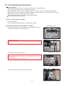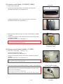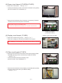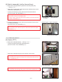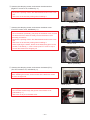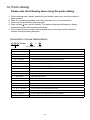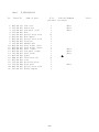
1
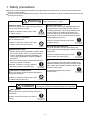
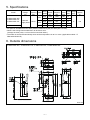
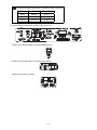
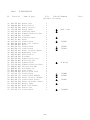
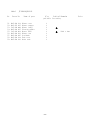
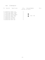
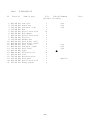
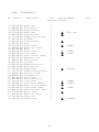
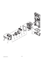
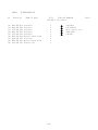
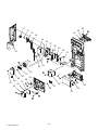
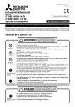
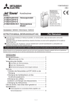
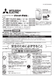
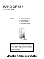
December 2012 HAND DRYER HANDBOOK Model: JT-SB216JSH-W-E JT-SB216JSH-H-E JT-SB216JSH-S-E JT-SB216KSN-W-E Nameplate Repair work must be performed by the manufacturer, its service agent or a similarly qualified person in order to avoid hazards. No. U180-A Contents 1. Safety precautions .................................................................... 3-4 2. Features ....................................................................................... 4 3. Improved points ............................................................................ 5 4. Names and functions of components .......................................... 6 5. Specifications .............................................................................. 7 6. Outside dimensions ..................................................................... 7 7. Electrical wiring diagrams ......................................................... 8-9 8. Circuit board diagrams .......................................................... 10-12 9. Fundamentals of operation ................................................... 13-14 10. Troubleshooting ..................................................................... 15-18 11. How to call .................................................................................. 18 12. Service inspection list ................................................................. 18 13. Overhauling procedures ........................................................ 19-26 14. Parts catalog ......................................................................... 27-59 JT-SB216JSH-W-E ......................................................... 28-35 JT-SB216JSH-H-E .......................................................... 36-43 JT-SB216JSH-S-E .......................................................... 44-51 JT-SB216KSN-W-E......................................................... 52-59 1. Safety precautions Be sure to read the following precautions thoroughly before the maintenance, and then inspect and repair the product in a safe manner. The types and levels of danger that may arise if the product is handled incorrectly are described with the warning symbols shown below. Warning Incorrect handling of the product may result in serious injury or death. Electric shock If you must inspect the circuitry while the power is on, do not touch the live parts. (Failure to heed this warning may result in electric shock.) Caution against electric shock Modification is prohibited Do not modify the unit. (Failure to heed this warning may result in electric shock.) (Failure to heed this warning may result in electric shock, fire and/or injury.) Prohibited Proper electric work • Use the electric wires designated for electric work, and conduct electric work in accordance with the "Electric Installation Engineering Standard", the "Indoor Wiring Regulations" and the installation instructions. • Be sure to check whether the terminals and fixed wiring are securely connected. (Improper connection or wiring installation may result in electric shock and/or fire.) Be sure to follow this instruction. Caution Be sure to follow this instruction. Use proper parts and tools For repair, be sure to use the parts listed in the service parts list of the applicable model and use the proper tools. (Failure to heed this warning may result in electric shock, fire and/or injury.) Be sure to follow this instruction. Check insulation Upon completing repair work, always measure the insulation resistance. Verify that it is at least 10 MΩ (with a 500 V DC insulation resistance tester), and then turn on the power. (Inadequate insulation may result in electric shock.) Scratches and deterioration Be sure to replace scratched and/or deteriorated wiring and lead wires. (Failure to heed this warning may result in electric shock and/or fire.) Turn off the power Be sure to turn off the earth leakage breaker and the power switch of the product's main unit prior to starting repair work. (The charge voltage in the circuitry remains for another 50 seconds or so, even after the power is turned off and the LED is unlit; therefore, wait for at least 50 seconds before disassembling the product.) Be sure to follow this instruction. Prohibited Incorrect handling of the product may result in serious injury or damage to properties including buildings and equipment. Wear gloves Always wear a pair of gloves during inspection or repair work. (Failure to heed this caution may result in injury.) Be sure to follow this instruction. ─3─ Request for repair ● Before repairs, take the product off the wall. ● Inspect the earth condition, and repair it if it is incomplete. Make sure that an earth leakage breaker or an overload protection device is installed, if it is not installed, recommend the dealer to install one. ● Check whether the air filter, side cover, and the drain tank are installed securely in place. ● Do not leave a towel or other object in the hand-drying area. ● Never place any object on the main body nor cover it. ● Make sure that the product is not being used in any of the following locations: • Outdoors • Locations where the temperature could be lower than 0°C • Locations where there is a lot of dust • Locations where the temperature could be higher than 40ºC • Locations where there is a lot of condensation • Locations where salt damage could occur • Vehicles (including ships and airplanes) • Locations where corrosive, neutral, or reductive gases are present. • Near food or tableware. • Kitchens • Locations where the appliance may come into direct contact with water. (Where there is a risk of water splashing.) • Locations where the appliance is in direct sunlight or strong light (It may cause sensor malfunction) • Rooms that have a sterilization basin, swimming pools, bathrooms. Make sure that the product operates properly upon completion of repair. Clean the product and the surrounding area, and then notify the customer of the completion of repair. 2. Features • Wide hand drying area: easy-to-use for people with big hands • Child sensor: easy-to-use for children • The wave nozzle has reduced operating sound by 1 dB. • Cleanable drain ditch • Joints of hand drying area has been reduced by half. • Exteriors can be cleaned by wiping with alcohol. • The square design matches various lavatories. ─4─ 3. Improved points Old model Item New model Old model New model JT-SB216ESH-W-CE JT-SB216JSH-W-E JT-SB216GSN-W-CE JT-SB216ESH-DG-CE JT-SB216JSH-H-E JT-SB216GSN-DG-CE JT-SB216KSN-W-E JT-SB216ESH-W-E JT-SB216GSN-W-E (Without a heater) JT-SB216JSH-S-E (With a thermal storage heater) (With a simple heater) (Without a heater) Appearance Drying time (sec.) Nozzle Noise (dB) Draining device 10 to 12 9 to 11 10 to 12 13 to 15 Hyper slit nozzle Wave nozzle Hyper slit nozzle Wave nozzle 59 61 59 58 Drain hose Cleanable drain ditch Drain hose Cleanable drain ditch 630 550 3.5 3.0 to 3.2 1010 to 1200 Rated power (During heat accumulation by the heater) consumption (W) 650 (Heater OFF) 4.6 to 5.0 (During heat accumulation by the heater) Rated current (A) 4.0 (Heater OFF) Weight (kg) Stand (Optional parts) 1240 (Heater ON) 720 (Heater OFF) 5.7 to 6.2 (Heater ON) 3.9 to 4.2 (Heater OFF) 14 11 12 11 JP-S15FS-H-E JP-S21FS2-H-E JP-S26FS-H-E JP-S21FS2-H-E ─5─ 4. Names and functions of components *Shaded areas in the figure indicate antibacterial material. Hand drying area Black wall area Blue light Power control section Switch door Main unit r Powe ON OFF Power switch Sensor The blue light does not have a sterilizing effect. Do not look directly into the blue light. Drain tank Side cover Display Air filter Heater type (JT-SB216JSH-W/H/S-E) Heater-less type (JT-SB216KSN-W-E) Power Power lamp Heater Heater lamp Power Power lamp Check Check lamp <JT-SB216JSH-W/H/S-E> Switches Switch box cover OFF STANDARD ON HEATER Mounting HIGH AIR SPEED screws Factory default settings Settings OFF / ON HEATER AIR SPEED STANDARD / HIGH Note: JT-SB216KSN-W-E is not equipped with those switches. ─6─ 5. Specifications Model Rated voltage (V) JT-SB216JSH-W-E JT-SB216JSH-H-E 220-240 JT-SB216JSH-S-E Single phase Rated Rated Power con- Air Drain tank Motor Noise Weight frequency Heater current sumption speed capacity speed (dB) (kg) (Hz) (A) (W) (m/s) (ℓ) ON 50-60 JT-SB216KSN-W-E OFF ― High 5.7-6.2 1240 106 61 Standard 4.9-5.3 1070 98 58 High 3.9-4.2 720 106 61 Standard 3.0-3.2 550 98 58 550 98 58 ― 3.0-3.2 11 0.8 • Air speed is calculated from the static pressure measured by the pitot tube (at the nozzle). • Noise is the A range value measured in an anechoic room. (Average as three points, 2 m from the front and both sides.) • The heater is turned off automatically when ambient temperature is 30°C or more. (Applicable models: JTSB216JSH-W/H/S-E) 6. Outside dimensions JT-SB216JSH-W-E, JT-SB216JSH-H-E, JT-SB216JSH-S-E, JT-SB216KSN-W-E Unit: mm ─7─ 7. Electrical wiring diagrams JT-SB216JSH-W-E, JT-SB216JSH-H-E, JT-SB216JSH-S-E ─8─ JT-SB216KSN-W-E ─9─ 8. Circuit board diagrams Circuit board diagrams and check points 1 Power circuit board (JT-30P3H [JT-SB216JSH-W/H/S-E] /JT-30P3 [JT-SB216KSN-W-E]) Heater power supply (JT-30P3H: Between TAB3-TAB4) Bus voltage (Being stopped): 310 V DC, 324 V DC, 338 V DC JT-SB216JSH-W/H/S-E: 220 V AC, 230 V AC, 240 V AC (With heater ON) (JT-30P3H/JT-30P3: Between TAB5 and 0 V or between TAB6 and 0 V) 15 V 0V Carrier frequency 15 kHz (JT-30P3H/JT-30P3: CN2 1P) (JT-30P3H/JT-30P3: CN2 3P) (JT-30P3H/JT-30P3: IC1 8P) 5V Reset input 5 V (JT-30P3H/JT-30P3: CN2 2P) (JT-30P3H/JT-30P3: IC1 18P) Power supply voltage: 220 V AC, 230 V AC, 240 V AC Clock frequency 12 MHz (JT-30P3H/JT-30P3: Between TAB1-TAB2) (JT-30P3H/JT-30P3: IC1 19P) ─ 10 ─ 2 Filter circuit board (JT-30F3) Power supply voltage: 220 V AC, 230 V AC, 240 V AC (JT-30F3: Between TAB20-TAB21) 3 Control circuit board (JT-30M3 [JT-SB216JSH-W/H/S-E] /JT-30M2 [JT-SB216KSN-W-E]) Clock frequency 8 MHz (JT-30M3/JT-30M2: IC20 14P) Reset input 5 V (JT-30M3/JT-30M2: IC20 11P) 5V (JT-30M3/JT-30M2: CN18 1P) 15 V (JT-30M3/JT-30M2: CN8 2P) ─ 11 ─ 0V (JT-30M3/JT-30M2: CN8 7P) Circuit thermostat characteristics (JT-30M3/JT-30M2: IC20 5P) Temperature Resistance IC20 5P Voltage 20°C 59.3 kΩ 3.44 V 30°C 37.6 kΩ 2.91 V 40°C 24.5 kΩ 2.38 V 4 Light receiving circuit board (JT-30S1) (Upper sensor) 5 Sensor circuit board (middle) (JT-30S2) (Middle sensor) 6 Sensor circuit board (lower) (JT-30S3) (Lower sensor) 7 Display circuit board (JT-30S5) ─ 12 ─ 9. Fundamentals of operation Descriptions of circuit operation (1) Notes for turning the power switch “ON / OFF” 1 When the power switch is turned “ON”, the power lamp (LED1), the heater lamp (LED2) (JT-SB216JSH-W/ H/S only, with the heater switch ON), and blue illumination lamps (LED10, 11) turn on after 1.5 seconds(*1), and the hand dryer becomes ready for operation. • Before the power lamp turns on, the hand dryer will not operate even if hands are inserted in the hand drying area. In the meantime, the microcomputer (IC20) of the main unit performs the initial settings, including the setting of the hand detection sensor sensitivity. • In order to set the sensitivity of the hand detection sensor correctly, do not insert hands in the hand drying area until the power lamp is turned on. • Even if the hand dryer has started immediately (within 15 seconds or less) after turning the power switch “ON”, it is normal though the motor input may become slightly lower due to the initial setting. *1: If the power switch is turned ON again 30 to 120 seconds after turning the power switch OFF, it may take 3 seconds before the operation is enabled. 2 When the power switch is turned “OFF”, the power lamp and blue illumination lamps turn off and operation stops. • The circuitry takes about 50 seconds to discharge the voltage retained in it. Wait until the discharging time elapses before plugging in or out the connectors, replacing the circuit boards, or doing other maintenance. • Even when any error is occurred, the error display will go off if the power switch has been turned off. Only when a microcomputer error is occurred, the error display persists till the voltage retained in the circuitry has been discharged (till the microcomputer has been reset). (2) Hand detection and operation 1 The hand detection sensors are infrared sensors containing the light emitting sensor (infrared LED) and light receiving sensor (photo-diode), etc. and consist of the upper sensor, the middle sensors, and the lower sensor. 2 Reflection type upper sensor: This sensor detects the change in the reflected amount of infrared light when hands are inserted. Transmission type middle and lower sensors: These sensors detect that the infrared light is shielded when hands are inserted. 3 When the lower or middle sensors detect hands, the blower motor turns on and the hand dryer starts to operate. 4 Once operation has started, it continues as long as any of the upper, middle, or lower sensors detects hands. 5 If 1.5 to 3 seconds elapse without detecting hands by any of the sensors, the blower motor turns off and operation stops. 6 The hand dryer continuously operates for up to 30 seconds. • Once 30 seconds have elapsed, the hand dryer stops operating even if hands are detected. • Since this is a function to assume the presence of a foreign object, the operation will resume if hands are pulled out and reinserted. ─ 13 ─ (3) Control of the heater (Applicable models: JT-SB216JSH-W/H/S-E) 1 The heater turns ON simultaneously with the blower motor turns ON. (The heater lamp turns on.) 2 The heater does not turn ON in the following occasions: • When the heater switch is turned “OFF” • When the circuit thermostat detection temperature on the control circuit board (JT-30M3) is 32°C or higher (4) Turning ON/OFF of the blue illumination lamps (Applicable models: JT-SB216JSH-W/H/S-E) 1 While the power is ON and the motor is stopping, switching the air speed switch six times within 5 seconds turns off the blue illumination lamps. (The switching can be started from either side of HIGH or STANDARD.) 2 Also when turning the illumination lamps on from off, perform the switching in the same way as described in 1. ─ 14 ─ 10. Troubleshooting Work precautions • When servicing, be sure to recreate the malfunction two or three times before starting repairs. • When servicing, always take care to keep proper footing. • Before starting the service, always unplug the power cord from the outlet, or turn off the earth leakage breaker when no power cord plug is provided. Sufficient care must be taken to avoid electric shock or injury. • Make sure to connect the power supply wires correctly. • When removing the circuit board, always hold it at both ends and remove carefully so as not to apply force to the surface mounted parts. • When removing the circuit board, be careful of the metal edges on the board. • When removing or inserting the connectors for the circuit board, hold the entire housing section. Never pull on the lead wires. • When circuit board failure is considered to be a cause, check closely for any broken section on the copper foil patterns, burning or discoloration of parts. • After replacing a circuit board, make sure to restore the same settings as before the replacement. Description of the error mode display <JT-SB216JSH-W/H/S-E> Power LED : ON : OFF Heater LED <JT-SB216KSN-W-E> Power LED Check LED : Slow blinking (ON for 0.4 seconds/ OFF for 0.4 seconds) : Fast blinking (ON for 0.1 second/ OFF for 0.1 second) Troubles with error display Error Mode Display Power Checkpoint Power supply Heater/Check voltage (Fuse is blown) Check Method and Remedy Check that the power switch is turned ON and that approx. 220 to 240 V AC is supplied at both ends of the power cord connections on the terminal block. ■ If 220 to 240 V AC is not supplied, check the following points. 1 Check if the earth leakage breaker is turned ON. 2 Check if the power cord is connected securely to the terminal block. Power supply Check that approx. 220 to 240 V AC is supplied between TAB1 and voltage on the TAB2 (orange) on the power circuit board (JT-30P3H/JT-30P3). power circuit board (JT-30P3H/ JT-30P3) ●If 220 to 240 V AC is not supplied, check the following points. Power supply Check that approx. 220 to 240 V AC is supplied to the following voltage on the points in the order of 1 and 2. filter circuit board 1 Between TAB20 and TAB21 (red) If approx. 220 to 240 V AC is not supplied, replace the power (JT-30F3) switch (assembly). 2 Between TAB22 and TAB23 (orange) If approx. 220 to 240 V AC is not supplied, replace the filter circuit board (JT-30F3). ●When 220 to 240 V AC is supplied, check the following points. Connector disCheck if the connector CN19 on the display circuit board (JT-30S5) connection for or CN18 on the control circuit board (JT-30M3/JT-30M2) is disconthe display circuit nected. board (JT-30S5) ─ 15 ─ Error Mode Display Power Checkpoint Check Method and Remedy Connector discon- Check if the connector CN2 on the power circuit board (JT-30P3H/ Heater/Check nection between JT-30P3) or CN5 on the control circuit board (JT-30M3/JT-30M2) is the circuit boards disconnected. Malfunction of If no error is found after checking the above, replace the control the control circuit circuit board (JT-30M3/JT-30M2). board (JT-30M3/ JT-30M2) (Fuse is blown) Malfunction of If the hand dryer does not operate even after replacing the control the power circuit circuit board (JT-30M3/JT-30M2), replace the power circuit board board (JT-30P3H/ (JT-30P3H/JT-30P3). JT-30P3) Power Heater/Check or (Tamper-proof timer) Leftover object Check for any objects left over and shielding the sensor in the hand drying area. Dirty sensor window Dirt may shield the sensors. Wipe the dirt off the sensor window. Connector disCheck if the following connectors are disconnected. connection for the 1 Sensor circuit board (lower) (JT-30S3) connector CN12 sensors 2 Sensor circuit board (middle) (JT-30S2) (2 locations) connectors CN15 3 Light receiving circuit board (JT-30S1) connector CN11 4 Control circuit board (JT-30M3/JT-30M2) connectors CN7 and CN8 Malfunction of If no error is found after checking the above, replace the control the control circuit circuit board (JT-30M3/JT-30M2). board (JT-30M3/ JT-30M2) Power Heater/Check (Overvoltage or undervoltage detection) Power Heater/Check (Motor start error) (Motor lock) (Motor over-revolution) Power Heater/Check (Motor overcurrent error) (Current detection circuit error) Abnormal power supply voltage Malfunction of the power circuit board (JT-30P3H/ JT-30P3) Check if correct power supply voltage is applied. • The error will occur if the power supply voltage is approx. 359 V AC or over, or approx. 127 V AC or under. *Note: If 359 V AC or over is applied, a current fuse on the power circuit board (JT-30P3H/JT-30P3) may blow. If no error is found after checking the above, replace the power circuit board (JT-30P3H/JT-30P3). Motor malfunction Check if the motor is locked or turns smoothly by hand. Malfunction of If no error is found after checking the above, replace the power the power circuit circuit board (JT-30P3H/JT-30P3). board (JT-30P3H/ JT-30P3) Blower (assembly) malfunction If the error display persists after replacing the power circuit board (JT-30P3H/JT-30P3), replace the blower (assembly). Motor overload Check for causes of motor overload. (Too much higher power supply voltage, any object disturbing the motor revolution, etc.) Connector disCheck if the motor lead wire connectors (black, white, and red) are connection for the disconnected. motor Blown thermal Measure the resistance between Red - White and Red - Black of fuse of the motor the motor lead wires. If it is ∞Ω, replace the blower (assembly). Malfunction of If no error is found after checking the above, or if the error display the power circuit persists after replacing the blower (assembly), replace the power board (JT-30P3H/ circuit board (JT-30P3H/JT-30P3). JT-30P3) ─ 16 ─ Error Mode Display Power Heater/Check (Motor signal error) Power Heater/Check (Microcomputer error) Checkpoint Check Method and Remedy Connector discon- Check if the connector CN5 on the control circuit board (JT-30M3/ nection JT-30M2) or CN2 on the power circuit board (JT-30P3H/JT-30P3) is disconnected. Malfunction of If no error is found after checking the above, replace the power the power circuit circuit board (JT-30P3H/JT-30P3). board (JT-30P3H/ JT-30P3) Malfunction of Replace the control circuit board (JT-30M3/JT-30M2). the control circuit board (JT-30M3/ JT-30M2) Troubles without error display Symptom Warm air does not blow. (JT-SB216JSH-W/H/S-E) Cause Heater switch Check Method and Remedy Check if the heater switch is turned ON. (Heater lamp lights with the heater switch ON.) Connector disCheck if the connectors TAB3 and TAB4 on the power circuit board connection for the (JT-30P3H) are disconnected. heater Blown thermal Measure the resistance between the connectors TAB3 and TAB4 fuse of the heater on the power circuit board (JT-30P3H). At a heater temperature of 0°C or over: 100 Ω or under If the fuse is blown, the resistance will be ∞ Ω. In this case, replace the heater (PTC) and the power circuit board (JT-30P3H). Malfunction of Check if approx. 220 to 240 V AC is output at both ends of the conthe power circuit nectors TAB3 and TAB4 on the power circuit board (JT-30P3H). If it board (JT-30P3H) is not output, replace the power circuit board (JT-30P3H). *Note: Approx. 220 to 240 V AC is output during operation, and it is not output during standby. Heater malfunction The hand dryer operates by itself. The hand dryer does not stop operation. If no error is found after checking the above, replace the heater (PTC). Connector disCheck if the following connectors are disconnected. connection for the 1 Sensor circuit board (lower) (JT-30S3) connector CN12 sensors 2 Sensor circuit board (middle) (JT-30S2) (2 locations) connectors CN15 3 Light receiving circuit board (JT-30S1) connector CN11 4 Control circuit board (JT-30M3/JT-30M2) connectors CN7 and CN8 Malfunction of Visually check the sensor circuit boards for a defect such as a the sensor circrack, corrosion, or a cold solder joint. cuit boards (JTIf the error persists after replacing the control circuit board (JT30M3/JT-30M2) in the next procedure, replace the defective sensor 30S1/2/3) circuit boards (JT-30S1/2/3). Malfunction of the control circuit board (JT-30M3/ JT-30M2) Air speed switch does not Connector disconnection change the air volume. (JT-SB216JSH-W/H/S-E) Malfunction of If no error is found after checking the above, replace the control circuit board (JT-30M3/JT-30M2). Check if the connector CN21 on the control circuit board (JT-30M3) or CN4 on the power circuit board (JT-30P3H) is disconnected. If no error is found after checking the above, replace the power the power circuit circuit board (JT-30P3H). board (JT-30P3H) ─ 17 ─ Symptom The hand dryer makes abnormal noises. Air blow is weak. Cause Check Method and Remedy Sucking of foreign Check for any foreign matter sticking to the blower (assembly) matter vanes. Clogged filter Incorrect wiring Check the filter for clogging with dust, etc. Check if the motor lead wires of the blower (assembly) (red to TAB7, white to TAB8, black to TAB9) are connected to incorrect TABs on the power circuit board (JT-30P3H/JT-30P3). (If they are connected incorrectly, the motor turns in the reverse direction.) Malfunction of If no error is found after checking the above, replace the power the power circuit circuit board (JT-30P3H/JT-30P3). board (JT-30P3H/ JT-30P3) 11. How to call Symptom Air blow is too weak to dry hands quickly. Remedy 1 Check if the filter is clogged. 2 Isn’t the air speed switch set at the STANDARD position? (Applicable models: JT-SB216JSH-W/H/S-E) Water leaks from the product. 1 Check if the drain tank is filled up. (Empty the drain tank.) *Note: Since the main unit may get flooded with water if the product operates with the drain tank is full, drain water will flow over when it is filled up beyond its capacity. 2 Is the drain tank installed properly? Air does not blow immediately after turning on the power switch and inserting hands. Initial setting takes 1.5 seconds after turning on the power switch. Operation is disabled in the meantime. Warm air does not blow. (JT-SB216JSH-W/H/S-E) Is the heater switch turned ON? The product has an abnormal odor. 1 Check if the drain tank is filled up. (Empty the drain tank.) 2 Check the inside of the drain tank for any foreign matter. (Remove it.) 3 Is the inside of the side cover cleaned up? 12. Service inspection list Location Electric wiring Operation Inspection Item Are lead wire connectors connected securely? Is the wiring correct? Does it operate properly? Isn’t there any abnormal noise, vibration, etc? Heater Is warm air blown? (JT-SB216JSH-W/H/S-E) Do the lamps, the power lamp (LED1), the heater lamp (LED2) Lamps (JT-SB216JSH-W/H/S only, with the heater switch ON), and blue illumination lamps (LED10, 11), turn on? Wall installation Isn’t there clearance between the product and the back wall? ─ 18 ─ Check Result 13. Overhauling procedures Work precautions • Before replacing parts, follow the instructions described in the troubleshooting. • When servicing, always take care to keep proper footing. • Before starting the service, always unplug the power cord from the outlet, or turn off the earth leakage breaker when no power cord plug is provided. Sufficient care must be taken to avoid electric shock or injury. • Make sure to connect the power supply wires correctly. • After completing repairs, check that the unit operates properly. Always wear gloves when servicing. (1) Turn off the power supply. 1 Stop the operation. 2 Turn off the earth leakage breaker on the distribution board. (2) Light receiving circuit board (JT-30S1) Maintenance cover 1 Unscrew the clamping screws, and remove the maintenance cover. (Two special screws 4 x 16, indicated by ) Assembly precaution Insert the maintenance cover into the groove of the base. (Indicated by ) 2 Remove the sensor fix plate (upper). Sensor fix plate (upper) Assembly precautions • Run the lead wires through the groove of the maintenance cover. (Indicated by ) • Take care not to pinch the lead wires. Maintenance cover 3 Remove the light receiving circuit board (JT-30S1). ─ 19 ─ Light receiving circuit board (JT-30S1) (3) Control circuit board (JT-30M3/JT-30M2) Front panel 1 Draw out the drain tank. 2 Unscrew the clamping screws, and remove the front panel. (Two special screws 4×16, indicated by ) 3 Unscrew the clamping screw, and remove the cover (micon). (One special screw 4×16, indicated by ) cover (micon) 4 Disconnect the lead wires from the control circuit board (JT-30M3/ JT-30M2). 5 Unscrew the clamping screw, and remove the control circuit board (JT-30M3/JT-30M2). (One special screw 4×12, indicated by ) Assembly precaution Take care not to pinch the lead wires. Control circuit board (JT-30M3/JT-30M2) (4) Sensor circuit board (middle) (JT-30S2) 1 Remove the front panel. → See (3) 1 to 2. 2 Unscrew the clamping screws. (Two PTT screws 4×16, indicated by ) 3 Unscrew the clamping screws, and remove the sensor fix pieces (middle). (Two special screws 4×12, indicated by ) Assembly precaution Take care not to pinch the lead wires. Sensor fix piece (middle) 4 Remove the sensor circuit boards (middle) (JT-30S2). (Two locations) Sensor fix piece (middle) Assembly precautions • Insert the sensor circuit board (middle) between the claws of the sensor fix piece (middle). • Take care not to pinch the lead wires. • After installing the circuit board, make sure that the LED is upright. ─ 20 ─ Sensor circuit board (middle) (JT-30S2) (5) Power circuit board (JT-30P3H/JT-30P3) 1 Remove the front panel. → See (3) 1 to 2. 2 Unscrew the clamping screws, and remove the board cover (power). (Two PTT screws 4×16, indicated by ) Board cover (power) 3 Disconnect the lead wires from the power circuit board (JT-30P3H/ JT-30P3), and remove the power circuit board. Assembly precautions • Take care not to pinch the lead wires. • Connect the lead wires as printed on the power circuit board. Power circuit board (JT-30P3H/JT-30P3) (6) Display circuit board (JT-30S5) Display circuit board (JT-30S5) 1 Remove the board cover (power). → See (5) 1 to 2. 2 Remove the display circuit board (JT-30S5) from the spacer. Assembly precaution After installing the circuit board, make sure that all LEDs are upright. Spacer (7) Filter circuit board (JT-30F3) 1 Disconnect the lead wires for the filter circuit board (orange) (TAB1 and TAB2) from the power circuit board (JT-30P3H/JT-30P3). → See (5) 1 to 3. 2 Unscrew the side panel (left) clamping screw. (One PTT screw 4×16, indicated by ) Filter circuit board lead wires (orange) 3 Disconnect the lead wires for the display circuit board (blue) (CN18) from the control circuit board (JT-30M3/JT-30M2). → See (3) 3 to 4. ─ 21 ─ Display circuit board lead wires (blue) 4 Unscrew the clamping screw, and remove the terminal block cover. (One PTT screw 4×16, indicated by ) Terminal block cover 5 Remove the side panel (left) in the direction of the arrow. Panel (back) Side panel (left) Assembly precautions • Fit the side panel (left) into the groove of the panel (back) and the base. (Indicated by ) • Carry out wiring after screwing the side panel (left). 6 Unscrew the clamping screw, and remove the board cover (filter). (One PTT screw 4×6, indicated by ) Board cover (filter) 7 Unscrew the clamping screw, and remove the terminal block fix plate from the side panel (left). (One PTT screw 4×16, indicated by ) Terminal block fix plate 8 Disconnect the lead wires from the filter circuit board (JT-30F3). 9 Remove the spacers (four locations, indicated by ), and then remove the filter circuit board (JT-30F3). (Pinch the spacers from the back for easier removal.) Side panel (left) ─ 22 ─ Filter circuit board (JT-30F3) (8) Switch (assembly) (with a thermal fuse) 1 Remove the terminal block fix plate from the side panel (left). → See (7) 1 to 7. 2 Remove the power switch lead wires (brown and blue) from the terminal block. (Indicated by ) 3 Unscrew the clamping screw, and remove the terminal block. (One PTT screw 4×6, indicated by ) Assembly precautions • Take care not to pinch the lead wires. • Hook the claw of the terminal block fix holder to the terminal block fix plate. (Indicated by ) 4 Unscrew the clamping screw, and remove the switch fix piece and the switch (assembly). (One PPT screw 3×8, indicated by ) Terminal block fix holder Terminal block Switch fix piece Switch (assembly) Assembly precaution Hook the claw of the switch fix piece to the terminal block fix plate. (Indicated by ) Terminal block fix plate For JT-SB216JSH-W/H/S-E (9) Heater (PTC) 1 Remove the side panel (left). → See (7) 1 to 5. 2 Unscrew the side panel (right) clamping screw. (One PTT screw 4×16, indicated by ) 3 Remove the side panel (right) in the direction of the arrow. Assembly precaution Fit the side panel (right) into the groove of the panel (back) and the base. (Indicated by ) Side panel (right) Assembly precaution Run the lead wires through the groove of the base. (Indicated by ) ─ 23 ─ Panel (back) 4 Unscrew the clamping screws, and remove the exhaust duct. (Eight PTT screws 4×16, indicated by ) Assembly precautions • Replace the packing used in the disassembled section with a new one. • Take care not to twist the packing when installing it. Exhaust duct 5 Unscrew the clamping screws, and remove the blower cover. (Four PTT screws 4×16, indicated by ) Precaution • Since the blower (assembly) may drop off the blower case, remove the lead wires first, and then slowly remove the blower cover. Assembly precautions • Replace the packing used in the disassembled section with a new one. • Take care not to twist the packing when installing it. • When replacing the heater, attach the included fixing piece to the position, indicated by , with a screw (one PTT screw 4×16) to prevent the blower from dropping off. Blower cover Blower (assembly) 6 Unscrew the clamping screws, and remove the heater (PTC). (Two PTT screws 4×16, indicated by ) Assembly precaution When installing the heater, set the heater as the lead wire comes out from the right side. Heater (PTC) Assembly precautions • Run the lead wires through the groove of the blower cover. (Indicated by ) • Take care not to pinch the lead wires. ─ 24 ─ Lead wire (10) Blower (assembly) 1 Remove the blower cover. → See (9) 1 to 5. Set the blower horizontally. Precaution • Since the blower (assembly) may drop off the blower case, remove the lead wires first, and then slowly remove the blower cover. Assembly precautions • When replacing the blower (assembly), attach the included fixing piece to the position, indicated by , with a screw (one PTT screw 4×16). • Set the blower (assembly) as the lead wire outlet comes to the position indicated by . • The part of the lead wires covered by the white code tube must pass through the code bush. (Indicated by ) Blower (assembly) 2 Remove the blower (assembly). 3 Remove the ferrite core from the blower lead wires. Ferrite core (11) Sensor circuit board (lower) (JT-30S3) 1 Remove the blower (assembly). → See (10) 1 to 2. 2 Unscrew the clamping screws, and remove the blower case. (Three PTT screws 4×16, indicated by ) Blower case 3 Unscrew the panel (front) and panel holder clamping screws, and remove the panel holders (left and right). (Five PTT screws 4×16, indicated by ) Panel (front) Panel holder (left) ─ 25 ─ Panel holder (right) 4 Tilt the panel (front) in the direction of the arrow, and remove it. 5 Remove the sensor fix holder (lower). Assembly precaution Take care not to pinch the lead wires. Sensor fix holder (lower) 6 Unhook the claw of the sensor fix holder (lower) (one location, indicated by ), and remove the sensor circuit board (lower) (JT-30S3). Sensor circuit board (lower) Sensor fix holder (lower) (JT-30S3) When reassembling Reassemble the unit in the reverse order of disassembly. After reassembly, always make a test run to be sure that the unit operates properly. ─ 26 ─ 14. Parts catalog Please note the following when using the parts catalog. 1. When ordering parts, always indicate the part number, part name, and the number of parts required. 2. Parts are not always available, and it may take time for you to receive them. 3. There may be specification improvements. 4. Parts marked are critical for safety. To maintain safety and performance, always replace these parts with the parts prescribed. 5. The numbers that are circled in the exploded view are the same as the reference number for the part being indicated. Description of screw abbreviations Screw 4 × Screw diameter 16 Length Abbreviation Description PC screw Cross recess flat head machine screw PRC screw Cross recess oval head machine screw PP screw Cross recess pan head machine screw SW · PP screw Cross recess pan head screw with spring washer PPT screw Cross recess tapping screw PCT screw Cross recess flat head tapping screw PTT screw Cross recess truss head tapping screw PT screw Cross recess truss head machine screw SET screw Slotted head stop screw SQ · SET screw Square head stop screw P · SET screw Pan head stop screw PMT screw Primer truss head screw HS · SET screw Hexagon head stop screw P · R · W screw Cross recess round wood screw P · C · W screw Cross recess flat head wood screw P · R · C · W screw Cross recess round and flat wood screw R · W screw Slotted round wood screw PW · PP screw Cross recess pan head screw with small washer SW-PW · PP screw Cross recess pan head machine screw with spring washer and flat washer ─ 27 ─ JT-SB216JSH-W-E 4 5 6 7 8 1 2 3 16 14 16 16 16 16 15 13 16 12 11 10 16 9 21 18 19 20 ─ 28 ─ JT-SB216JSH-W-E 16 17 Model No. 1. 2. 3. 4. 5. 6. 7. 8. 9. 10. 11. 12. 13. 14. 15. 16. 17. 18. 19. 20. 21. JT-SB216JSH-W-E Parts No. M45 Y45 Y45 Y45 D41 M45 M45 M45 Y45 M45 M45 M45 M45 Y45 M45 H00 M45 Y45 Y45 M45 Y45 684 622 622 622 233 684 632 684 622 684 684 684 684 622 665 163 684 623 623 632 623 817 807 806 805 018 805 047 802 802 824 825 803 832 801 806 007 804 809 800 045 358 Name of part Side cover Switch door Side panel (left) Base Special screw 4×16 Hook (upper) Special screw 4×16 Fix plate Exhaust duct Panel holder (left) Panel holder (right) Panel (front) Side panel (right) Panel (back) Filter PTT screw 4×16 Cover Decoration plate Front panel Special screw 4×16 Wiring diagram Q'ty Critical Remarks pcs/unit for safety 1 1 1 1 13 1 2 1 1 1 1 1 1 1 1 31 1 1 1 3 1 -29- White White White White White White White Price 31 32 33 44 34 35 36 37 38 42 16 43 48 47 53 47 48 49 56 55 50 57 51 58 52 5 41 54 16 16 59 56 61 48 48 48 62 65 64 63 58 59 56 ─ 30 ─ JT-SB216JSH-W-E 40 46 47 60 20 39 45 Model No. 31. 32. 33. 34. 35. 36. 37. 38. 39. 40. 41. 42. 43. 44. 45. 46. 47. 48. 49. 50. 51. 52. 53. 54. 55. 56. 57. 58. 59. 60. 61. 62. 63. 64. 65. JT-SB216JSH-W-E Parts No. M45 H00 M45 Y45 M45 Y45 M45 M45 M35 Y45 M45 M45 M45 M45 M45 M45 H00 M45 M45 H00 K81 Y45 H00 H00 M45 M34 Y45 M45 M45 M45 M45 Y45 M45 Y45 Y45 679 003 684 622 684 622 640 684 717 622 684 606 684 684 684 684 312 649 684 141 432 622 011 013 684 869 623 684 684 684 684 622 684 622 623 228 005 820 220 823 804 226 821 095 173 822 095 176 172 831 828 007 226 826 005 236 808 008 076 834 018 172 173 829 174 830 803 827 180 171 Name of part Q'ty Critical Remarks pcs/unit for safety Switch cover PPT screw 3×8 Switch fix piece Switch (assy) Insulation sheet Terminal block fix plate Cord bush Insulation sheet Spacer Circuit board Board cover (filter) Spacer Circuit board Circuit board Sensor fix plate (upper) Maintenance cover PTT screw 4×6 Cord bush Terminal block cover PPT screw 4×20 Terminal block Terminal block fix holder PT screw 4×8 (BS) Lock washer (4) Cover (micon) Special screw 4×12 Circuit board Circuit board (middle) Sensor fix piece (middle) Circuit board (lower) Sensor fix holder (lower) Reactor (assy) Board cover (power) Ferrite core Circuit board 1 1 1 1 1 1 1 1 4 1 1 1 1 1 1 1 3 5 1 2 1 1 2 2 1 3 1 2 2 1 1 1 1 1 1 -31- With a fuse JT-30F3 JT-30S5 JT-30S1 3P ML-20 JT-30M3 JT-30S2 JT-30S3 JT-30P3H Price 16 16 77 78 76 75 74 73 72 16 71 ─ 32 ─ JT-SB216JSH-W-E 79 Model No. 71. 72. 73. 74. 75. 76. 77. 78. 79. JT-SB216JSH-W-E Parts No. M45 M45 Y45 M45 Y45 M45 M45 M45 M45 684 673 622 664 623 684 684 684 684 811 227 400 227 801 833 225 814 813 Name of part Blower cover Blower stopper Blower (assy) Floating rubber Heater (PTC) Blower case Cord bush Tank cover Drain tank Q'ty Critical Remarks pcs/unit for safety 1 1 1 1 1 1 1 1 1 -33- With a fuse Price 91 92 93 95 94 96 97 98 99 16 1 piece shows accessory parts. ─ 34 ─ JT-SB216JSH-W-E Model No. 91. 92. 93. 94. 95. 96. 97. 98. 99. JT-SB216JSH-W-E Parts No. M45 M45 Y45 M45 Y45 M45 D40 M45 Y45 684 684 622 684 623 636 134 693 622 221 220 219 223 219 018 227 017 179 Name of part Lead wire Lead wire Lead wire Lead wire Lead wire Special screw 5×30 Cord clip Special screw 4×12 Ferrite core Q'ty Critical Remarks pcs/unit for safety 1 1 1 1 1 6 1 1 1 -35- CN8-CN11 CN7-CN12,15 With a ferrite core CN18-CN19 CN2-CN5 Price JT-SB216JSH-H-E 4 5 6 7 8 1 2 3 16 14 16 16 16 16 15 13 16 12 11 10 16 9 21 18 19 20 ─ 36 ─ JT-SB216JSH-H-E 16 17 Model No. 1. 2. 3. 4. 5. 6. 7. 8. 9. 10. 11. 12. 13. 14. 15. 16. 17. 18. 19. 20. 21. JT-SB216JSH-H-E Parts No. M45 Y45 Y45 Y45 D41 M45 M45 M45 Y45 M45 M45 M45 M45 Y45 M45 H00 M45 Y45 Y45 M45 Y45 684 623 623 622 233 684 632 684 622 684 684 684 684 623 665 163 684 623 623 632 623 841 807 806 805 018 805 047 802 802 824 825 838 843 803 806 007 804 809 802 045 358 Name of part Side cover Switch door Side panel (left) Base Special screw 4×16 Hook (upper) Special screw 4×16 Fix plate Exhaust duct Panel holder (left) Panel holder (right) Panel (front) Side panel (right) Panel (back) Filter PTT screw 4×16 Cover Decoration plate Front panel Special screw 4×16 Wiring diagram Q'ty Critical Remarks pcs/unit for safety 1 1 1 1 13 1 2 1 1 1 1 1 1 1 1 31 1 1 1 3 1 -37- Gray Gray Gray Gray Gray Gray Gray Price 31 32 33 44 34 35 36 37 38 42 16 43 48 47 53 47 48 49 56 55 50 57 51 58 52 5 41 54 16 16 59 56 61 48 48 48 62 65 64 63 58 59 56 ─ 38 ─ JT-SB216JSH-H-E 40 46 47 60 20 39 45 Model No. 31. 32. 33. 34. 35. 36. 37. 38. 39. 40. 41. 42. 43. 44. 45. 46. 47. 48. 49. 50. 51. 52. 53. 54. 55. 56. 57. 58. 59. 60. 61. 62. 63. 64. 65. JT-SB216JSH-H-E Parts No. M45 H00 M45 Y45 M45 Y45 M45 M45 M35 Y45 M45 M45 M45 M45 M45 M45 H00 M45 M45 H00 K81 Y45 H00 H00 M45 M34 Y45 M45 M45 M45 M45 Y45 M45 Y45 Y45 679 003 684 622 684 622 640 684 717 622 684 606 684 684 684 684 312 649 684 141 432 622 011 013 684 869 623 684 684 684 684 622 684 622 623 228 005 820 220 823 804 226 821 095 173 822 095 176 172 831 828 007 226 826 005 236 808 008 076 834 018 172 173 829 174 830 803 827 180 171 Name of part Q'ty Critical Remarks pcs/unit for safety Switch cover PPT screw 3×8 Switch fix piece Switch (assy) Insulation sheet Terminal block fix plate Cord bush Insulation sheet Spacer Circuit board Board cover (filter) Spacer Circuit board Circuit board Sensor fix plate (upper) Maintenance cover PTT screw 4×6 Cord bush Terminal block cover PPT screw 4×20 Terminal block Terminal block fix holder PT screw 4×8 (BS) Lock washer (4) Cover (micon) Special screw 4×12 Circuit board Circuit board (middle) Sensor fix piece (middle) Circuit board (lower) Sensor fix holder (lower) Reactor (assy) Board cover (power) Ferrite core Circuit board 1 1 1 1 1 1 1 1 4 1 1 1 1 1 1 1 3 5 1 2 1 1 2 2 1 3 1 2 2 1 1 1 1 1 1 -39- With a fuse JT-30F3 JT-30S5 JT-30S1 3P ML-20 JT-30M3 JT-30S2 JT-30S3 JT-30P3H Price 16 16 77 78 76 75 74 73 72 16 71 ─ 40 ─ JT-SB216JSH-H-E 79 Model No. 71. 72. 73. 74. 75. 76. 77. 78. 79. JT-SB216JSH-H-E Parts No. M45 M45 Y45 M45 Y45 M45 M45 M45 M45 684 673 622 664 623 684 684 684 684 811 227 400 227 801 833 225 814 839 Name of part Blower cover Blower stopper Blower (assy) Floating rubber Heater (PTC) Blower case Cord bush Tank cover Drain tank Q'ty Critical Remarks pcs/unit for safety 1 1 1 1 1 1 1 1 1 -41- With a fuse Price 91 92 93 95 94 96 97 98 99 16 1 piece shows accessory parts. ─ 42 ─ JT-SB216JSH-H-E Model No. 91. 92. 93. 94. 95. 96. 97. 98. 99. JT-SB216JSH-H-E Parts No. M45 M45 Y45 M45 Y45 M45 D40 M45 Y45 684 684 622 684 623 636 134 693 622 221 220 219 223 219 018 227 017 179 Name of part Lead wire Lead wire Lead wire Lead wire Lead wire Special screw 5×30 Cord clip Special screw 4×12 Ferrite core Q'ty Critical Remarks pcs/unit for safety 1 1 1 1 1 6 1 1 1 -43- CN8-CN11 CN7-CN12,15 With a ferrite core CN18-CN19 CN2-CN5 Price JT-SB216JSH-S-E 4 5 6 7 8 1 2 3 16 14 16 16 16 16 15 13 16 12 11 10 16 9 21 18 19 20 ─ 44 ─ JT-SB216JSH-S-E 16 17 Model No. 1. 2. 3. 4. 5. 6. 7. 8. 9. 10. 11. 12. 13. 14. 15. 16. 17. 18. 19. 20. 21. JT-SB216JSH-S-E Parts No. M45 Y45 Y45 Y45 D41 M45 M45 M45 Y45 M45 M45 M45 M45 Y45 M45 H00 M45 Y45 Y45 M45 Y45 684 623 623 622 233 684 632 684 622 684 684 684 684 623 665 163 684 623 623 632 623 841 807 806 805 018 805 047 802 802 824 825 838 843 803 806 007 804 809 804 045 358 Name of part Side cover Switch door Side panel (left) Base Special screw 4×16 Hook (upper) Special screw 4×16 Fix plate Exhaust duct Panel holder (left) Panel holder (right) Panel (front) Side panel (right) Panel (back) Filter PTT screw 4×16 Cover Decoration plate Front panel Special screw 4×16 Wiring diagram Q'ty Critical Remarks pcs/unit for safety 1 1 1 1 13 1 2 1 1 1 1 1 1 1 1 31 1 1 1 3 1 -45- Gray Gray Gray Gray Gray Gray Metallic Price 31 32 33 44 34 35 36 37 38 42 16 43 48 47 53 47 48 49 56 55 50 57 51 58 52 5 41 54 16 16 59 56 61 48 48 48 62 65 64 63 58 59 56 ─ 46 ─ JT-SB216JSH-S-E 40 46 47 60 20 39 45 Model No. 31. 32. 33. 34. 35. 36. 37. 38. 39. 40. 41. 42. 43. 44. 45. 46. 47. 48. 49. 50. 51. 52. 53. 54. 55. 56. 57. 58. 59. 60. 61. 62. 63. 64. 65. JT-SB216JSH-S-E Parts No. M45 H00 M45 Y45 M45 Y45 M45 M45 M35 Y45 M45 M45 M45 M45 M45 M45 H00 M45 M45 H00 K81 Y45 H00 H00 M45 M34 Y45 M45 M45 M45 M45 Y45 M45 Y45 Y45 679 003 684 622 684 622 640 684 717 622 684 606 684 684 684 684 312 649 684 141 432 622 011 013 684 869 623 684 684 684 684 622 684 622 623 228 005 820 220 823 804 226 821 095 173 822 095 176 172 831 828 007 226 826 005 236 808 008 076 834 018 172 173 829 174 830 803 827 180 171 Name of part Q'ty Critical Remarks pcs/unit for safety Switch cover PPT screw 3×8 Switch fix piece Switch (assy) Insulation sheet Terminal block fix plate Cord bush Insulation sheet Spacer Circuit board Board cover (filter) Spacer Circuit board Circuit board Sensor fix plate (upper) Maintenance cover PTT screw 4×6 Cord bush Terminal block cover PPT screw 4×20 Terminal block Terminal block fix holder PT screw 4×8 (BS) Lock washer (4) Cover (micon) Special screw 4×12 Circuit board Circuit board (middle) Sensor fix piece (middle) Circuit board (lower) Sensor fix holder (lower) Reactor (assy) Board cover (power) Ferrite core Circuit board 1 1 1 1 1 1 1 1 4 1 1 1 1 1 1 1 3 5 1 2 1 1 2 2 1 3 1 2 2 1 1 1 1 1 1 -47- With a fuse JT-30F3 JT-30S5 JT-30S1 3P ML-20 JT-30M3 JT-30S2 JT-30S3 JT-30P3H Price 16 16 77 78 76 75 74 73 72 16 71 ─ 48 ─ JT-SB216JSH-S-E 79 Model No. 71. 72. 73. 74. 75. 76. 77. 78. 79. JT-SB216JSH-S-E Parts No. M45 M45 Y45 M45 Y45 M45 M45 M45 M45 684 673 622 664 623 684 684 684 684 811 227 400 227 801 833 225 814 839 Name of part Blower cover Blower stopper Blower (assy) Floating rubber Heater (PTC) Blower case Cord bush Tank cover Drain tank Q'ty Critical Remarks pcs/unit for safety 1 1 1 1 1 1 1 1 1 -49- With a fuse Price 91 92 93 95 94 96 97 98 99 16 1 piece shows accessory parts. ─ 50 ─ JT-SB216JSH-S-E Model No. 91. 92. 93. 94. 95. 96. 97. 98. 99. JT-SB216JSH-S-E Parts No. M45 M45 Y45 M45 Y45 M45 D40 M45 Y45 684 684 622 684 623 636 134 693 622 221 220 219 223 219 018 227 017 179 Name of part Lead wire Lead wire Lead wire Lead wire Lead wire Special screw 5×30 Cord clip Special screw 4×12 Ferrite core Q'ty Critical Remarks pcs/unit for safety 1 1 1 1 1 6 1 1 1 -51- CN8-CN11 CN7-CN12,15 With a ferrite core CN18-CN19 CN2-CN5 Price JT-SB216KSN-W-E 4 5 6 7 8 1 2 3 16 14 16 16 16 16 15 13 16 12 11 10 16 9 21 18 19 20 ─ 52 ─ JT-SB216KSN-W-E 16 17 Model No. 1. 2. 3. 4. 5. 6. 7. 8. 9. 10. 11. 12. 13. 14. 15. 16. 17. 18. 19. 20. 21. JT-SB216KSN-W-E Parts No. M45 Y45 Y45 Y45 D41 M45 M45 M45 Y45 M45 M45 M45 M45 Y45 M45 H00 M45 Y45 Y45 M45 Y45 684 622 622 622 233 684 632 684 622 684 684 684 684 622 665 163 684 622 622 632 622 817 807 806 805 018 805 047 802 802 824 825 803 832 801 806 007 804 809 800 045 358 Name of part Side cover Switch door Side panel (left) Base Special screw 4×16 Hook (upper) Special screw 4×16 Fix plate Exhaust duct Panel holder (left) Panel holder (right) Panel (front) Side panel (right) Panel (back) Filter PTT screw 4×16 Cover Decoration plate Front panel Special screw 4×16 Wiring diagram Q'ty Critical Remarks pcs/unit for safety 1 1 1 1 13 1 2 1 1 1 1 1 1 1 1 29 1 1 1 3 1 -53- White White White White White White White Price 31 32 33 44 34 35 36 37 38 42 16 43 48 47 53 47 48 49 56 55 50 57 51 58 52 5 41 54 16 16 59 56 61 48 48 48 62 65 64 63 58 59 56 ─ 54 ─ JT-SB216KSN-W-E 40 46 47 60 20 39 45 Model No. 31. 32. 33. 34. 35. 36. 37. 38. 39. 40. 41. 42. 43. 44. 45. 46. 47. 48. 49. 50. 51. 52. 53. 54. 55. 56. 57. 58. 59. 60. 61. 62. 63. 64. 65. JT-SB216KSN-W-E Parts No. M45 H00 M45 Y45 M45 Y45 M45 M45 M35 Y45 M45 M45 M45 M45 M45 M45 H00 M45 M45 H00 K81 Y45 H00 H00 M45 M34 Y45 M45 M45 M45 M45 Y45 M45 Y45 Y45 679 003 684 622 684 622 640 684 717 622 684 606 684 684 684 684 312 649 684 141 432 622 011 013 684 869 622 684 684 684 684 622 684 622 622 228 005 820 220 823 804 226 821 095 173 822 095 176 172 831 828 007 226 826 005 236 808 008 076 834 018 172 173 829 174 830 803 827 180 171 Name of part Q'ty Critical Remarks pcs/unit for safety Switch cover PPT screw 3×8 Switch fix piece Switch (assy) Insulation sheet Terminal block fix plate Cord bush Insulation sheet Spacer Circuit board Board cover (filter) Spacer Circuit board Circuit board Sensor fix plate (upper) Maintenance cover PTT screw 4×6 Cord bush Terminal block cover PPT screw 4×20 Terminal block Terminal block fix holder PT screw 4×8 (BS) Lock washer (4) Cover (micon) Special screw 4×12 Circuit board Circuit board (middle) Sensor fix piece (middle) Circuit board (lower) Sensor fix holder (lower) Reactor (assy) Board cover (power) Ferrite core Circuit board 1 1 1 1 1 1 1 1 4 1 1 1 1 1 1 1 3 5 1 2 1 1 2 2 1 3 1 2 2 1 1 1 1 1 1 -55- With a fuse JT-30F3 JT-30S5 JT-30S1 3P ML-20 JT-30M2 JT-30S2 JT-30S3 JT-30P3 Price 16 76 77 75 74 73 72 16 71 ─ 56 ─ JT-SB216KSN-W-E 78 Model No. 71. 72. 73. 74. 75. 76. 77. 78. JT-SB216KSN-W-E Parts No. M45 M45 Y45 M45 M45 M45 M45 M45 684 673 622 664 684 684 684 684 811 227 400 227 833 225 814 813 Name of part Blower cover Blower stopper Blower (assy) Floating rubber Blower case Cord bush Tank cover Drain tank Q'ty Critical Remarks pcs/unit for safety 1 1 1 1 1 1 1 1 -57- Price 91 92 93 95 94 96 97 98 99 16 1 piece shows accessory parts. ─ 58 ─ JT-SB216KSN-W-E Model No. 91. 92. 93. 94. 95. 96. 97. 98. 99. JT-SB216KSN-W-E Parts No. M45 M45 Y45 M45 M45 M45 D40 M45 Y45 684 684 622 684 684 636 134 693 622 221 220 219 223 219 018 227 017 179 Name of part Lead wire Lead wire Lead wire Lead wire Lead wire Special screw 5×30 Cord clip Special screw 4×12 Ferrite core Q'ty Critical Remarks pcs/unit for safety 1 1 1 1 1 6 1 1 1 -59- CN8-CN11 CN7-CN12,15 With a ferrite core CN18-CN19 CN2-CN5 Price