1
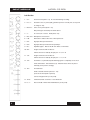
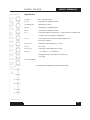
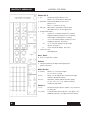
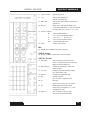
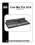
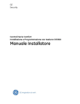
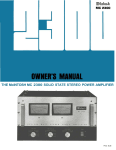
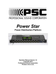
CS 208 PROFESSIONAL AUDIO MIXER
OPERATOR’S MANUAL
1411 Marsh Street, Suite 105 ! San Luis Obispo, CA 93401 ! (805) 782-9750 ! Fax: (805) 782-9752
www.coopersound.com
645 Main Street, Suite C
Morro Bay , CA 93442-2273
Phone: (805) 772-1007
Fax: (805) 772-1098
http://www.coopersound.com
USA
CS208
Cooper Sound Systems, Inc.
TABLE OF CONTENTS
INPUT CHANNEL DESCRIPTION ............................................................1, 2
OUTPUT MODULE DESCRIPTION ..........................................................3, 4
REAR PANEL DESCRIPTION ....................................................................... 5
PIN OUTS ..................................................................................................... 6
STEREO MODULE (OPTIONAL) ............................................................... 7, 8
SPECIFICATIONS
GENERAL. ............................................................................................. 9
INPUTS ................................................................................................. 10
OUTPUTS ............................................................................................. 11
BLOCK DIAGRAM - INPUT & POWER WIRING .......................................... 12
BLOCK DIAGRAM - OUTPUT ...................................................................... 13
EQ CHARTS ................................................................................................ 14
LAYOUT - A, B, C ......................................................................................... 15
LAYOUT - D, E, MB ...................................................................................... 16
LAYOUT - F, G, G PPM, H ........................................................................... 17
CSST BLOCK DIAGRAM & LAYOUTS ........................................................ 18
BASIC SET UP & METERING ................................................................. 19, 20
OPERATION & APPLICATION NOTES ................................. 21, 22, 23, 24, 25
APPLICATION NOTES
AN 1 ROLLS ................................................................................................ 26
AN 2A INPUT CHANNEL OPTIONS ............................................................ 27
AN 2B INPUT CHANNEL OPTIONS ............................................................ 28
AN 2C INPUT CHANNEL OPTIONS ............................................................ 29
AN 2D INPUT CHANNEL OPTIONS ............................................................ 30
AN 2E INPUT CHANNEL OPTIONS ............................................................ 31
AN 3 COMMUNICATIONS IN ...................................................................... 32
GENERAL NOTES ........................................................................................ 33
WARRANTY.................................................................................................. 34
MODEL CS 208
INPUT MODULE
Left Section
1. CH :
Channel Power (down = on) Do not switch during recording.
2. PH / T :
Phantom Power, ‘T’ power (AB). (phantom power is normally 48v, see layout A
to change to 12v).
3. Mic Pwr :
Turns on mic power (down = on).
Mic power type selected by the switch above.
4. ø :
N = normal, R = reverse. Audio phase only.
5. Mic / Line : Microphone or line level in.
6. Pad :
Attenuator to reduce either mic or line input levels.
7. HP1 :
High pass filter, pre-transformer.
8. HP2 :
High pass filter, post transformer & preAmps.
9. EQ :
Equalizer bypass. Affects HF, MF & LF filters, not HP filters.
10. AB :
Assigns channel to AB mix busses.
Further selection is made by the pan pot. A = L, B = R.
11. CD :
Assigns channel to CD mix busses.
Further selection is made by the pan pot. C = L, D = R.
12. Lim :
The limiter is a symmetrical peak detecting type & is completely out of circut
when switched off. Threshold: See (14). Attack & release times are preset
internally (see layout A to change).
13. PFL :
Pre-fade listen.
Sends selected channel to phones 1 only.
(Cuts out all other inputs to phones).
Can be changed to AFL (see layout A).
1
14. Thres :
Limiter threshold. Clockwise = lower threshold.
15. O / L :
Near overload or limiter threshold indicator (see layout A).
MODEL CS 208
INPUT MODULE
Right Section
16. Gain :
Mic / Line preAmp gain.
17. HF :
High frequency amplitude control.
18. MF 500, 5k :
Mid-frequency select.
19. MF :
Mid-frequency amplitude control.
20. LF :
Low frequency amplitude control.
21. S :
Invert phase option to B & D busses. 1 pair of channels could be used
to decode a M / S microphone configuration.
22. A1 :
Aux 1 send (the aux sends are not affected by the AB,
CD mix bus switches).
23. PF / AF :
Selects pre or after fader for Aux 1 send.
24. A2 :
Aux 2 send.
25. PF / AF :
Selects pre or after fader for Aux 2 send.
26. Pan :
L = A and/or C,
R = B and/or D.
Example: A out only. AB switch in, CD switch out,
Pan L (left).
27. Channel fader.
See specifications & application notes for further details.
2
MODEL CS 208
OUTPUT MODULE
Phones 2 & 3
1. PL :
Private line assign to phones 2 or 3
(down = on). See master PL switch (27).
2. Main/Aux : Selects main (ABCD) or Aux 1 & 2 to
phones 2 or 3.
(Aux 1 = L out, Aux 2 = R out.)
3. AB / CD :
When main is selected, this switch selects
either AB or CD to L, R of the phone outs.
4. Rotary Select Switch :
X
= phones 2 or 3 follows the phones 1 selection.
Example: Playback to phones 2 & 3 for director/
script critique. (Switch phones 1 to tape).
L
= A, C or A1 to both outputs. (ie: Mono to L & R
ST
headphone capsules). See (2 & 3).
= A, C, A1 to left capsule B, D, A2 to right
capsule. See (2 & 3).
R
= B, D, A2 to both outputs. See (2 & 3).
5. Phones 2/3 level :
Gain adjustment.
Aux 1, Aux 2
6. Aux 1, 2 master level controls.
Returns
7. Trim pots (multi-turn) to adjust return (tape) level to
phones 1 & meters.
Meter Section
8. CD/Aux :
Meters 3, 4 = CD or Aux outputs
(3 = C or A1, 4 = D or A2).
9. PFL :
Meters 1, 2 can indicate PFL selected on the input
10. T/D :
channels. (Momentary switch).
Tape/Direct. Meters indicate the return signals.
(1 = A, 2 = B, 3 = C, 4 = D). CD/Aux switch (8)
overides the tape return.
Phones 1
11. PL :
Private line assign to phones 1 (down = on) see master
12. Comm :
PL switch (27).
Communications return to phones 1 only. (down = on).
(Talkback to phones 1) (see app. notes for 2 returns).
3
MODEL CS 208
OUTPUT MODULE
13. Comm. Trimmer :
14. T / D :
Adjusts return level.
Tape or direct to phones 1.
See AB / CD below (16).
15. Main / Aux :
Selects either main, ABCD or Aux (A1, A2)
to phones 1.
16. AB / CD :
When main is selected, group AB or CD
is sub-selected to phones 1. This also controls
the tape return (A = L, B = R, C = L, D = R).
17. Phones 1 selector :
M
= Mono to both outputs.
L
ST
= A, C or A1 mono to both outputs.
= A, C, A1 = L.
B, D, A2 = R.
R
= B, D, A2 mono to both outputs.
M.S.
= M/S decode to phones 1.
Phones 1 gain control.
18. Level :
Mic
19. Internal slate microphone (See Ext. Slate) (21).
OSC/SL Assign
20. Assigns oscillator & slate to AB, CD or Aux outputs.
OSC, SL, PL, Roll
21. Ext. Slate :
Selects internal or external slate mic.
Down = external slate input on rear panel.
(Bypasses internal slate mic).
22. Slate Trimmer :
Controls level of both Int. & Ext. slate
23. 1k / 10k :
Frequency select for internal oscillator.
Up = 1kHz, down = 10k.
24. Trimmer :
Oscillator level (multi-turn pot).
25. Osc :
Internal oscillator.
(up = on, down = momentary on).
26. SL :
Slate mic.
(multi-turn pot).
down = with LF tone, up = no LF tone.
27. PL :
Master private line & level control.
Directs slate mic to phones 1, 2, 3 only.
28. Roll 1 & 2 :
Up = on, down = pause or stop.
See “pin outs” for further details.
Assigned by (1 & 11).
4
MODEL CS 208
REAR PANEL
1. Phones 2 :
Stereo 1/4” jack.
2. Phones 3 :
Stereo 1/4” jack.
3. Fuse :
4. Ext. Power In :
2.5A (5 x 20mm).
Pin 1 = negative DC, Pin 3 = Battery charge (positive), Pin 4 = Positive DC
5. A, B, C, D, A1, A2 :
Balanced XLR outputs (Pin 2 high)
6. Unbalanced Outs (TQG) :
7. Unbalanced Outs (DB9) :
ABCD Pin 1 = ground, Pin 2 = signal.
ABCD.
8. Mix Bus In :
ABCD (current input).
9. Comm. In :
10. Slate :
Talkback to phones 1. Balanced input. Stereo 1/4” jack.
External slate mic input. Mono 1/4” jack.
11. Roll 1, 2 :
See pin outs.
12. Returns :
13. Ch. Dir. Out :
ABCD Balanced in. Stereo 1/4” jack.
Channel direct out, post fader. Mono 1/4” jack.
14. Ch. Insert :
Can be direct out, pre-fader (see board A layout). Unbalanced stereo 1/4” jack.
15. 2 spare holes :
Option for stereo input channels.
(see specifications).
5
MODEL CS 208
PIN OUTS
All XLR’s are wired pin 2 high and are
transformer balanced.
XLR 3M
Insert
1/4” stereo jack
Tip = Send
Ring = Return
Sleeve = Ground
or direct out, pre-fader
(see app. note AN 2A & 2B)
Pin 1 = Ground
Pin 2 = High
Pin 3 = Low
Phones 1, 2, 3
1/4” stereo jack (max load = 25! per channel)
Tip = Left
Ring = Right
Sleeve = Ground
Direct Out
(post-fader)
1/4” mono jack
Tip = Signal
Sleeve = Ground
Mix Bus In
DB9
Comm. In
1/4” stereo jack
Tip = High
1 = Ground
Ring = Low
2=D
Sleeve = Ground
(See application note AN 3 for multiple inputs)
3=C
4=A
5=B
(current input, see specifications)
Returns
1/4” stereo jack
Tip = High
Outputs
DB9
1 = Ground
2=A
3=B
4=C
5=D
TQG 3M
Pin 1 = Ground
Ring = Low
Sleeve = Ground
Ext. Slate In
1/4” mono/stereo jack
Tip = Signal
Ring & Sleeve = Ground
Pin 2 = Signal
Pin 3 = N/C
TQG 5M (roll) (See application note AN 1)
Pin1 = -10 v (Nagra)
Pin 2 = Stop (Nagra)
Pin 3 = Pause/Stop (DATs)
Pin 4 = Common (DATs)
Pin 5 = Record (DATs)
6
MODEL CS 208
CSST-STERE0 MODULE
1. CH.
Channel power (down = on). Do not switch during recording.
2. PH/DYN/T
Mic Power -
Phantom = 48v * (see notes).
Dynamic = no power.
T
3. ø
Audio phase only.
= tonader power (AB).
N = normal.
R = reverse.
4. Mic/Line
Microphone or line level in.
5. PAD
Attenuator to reduce mic or line input levels.
6. HP1
High pass filter, pre-transformer.
7. HP2
High pass filter, post-transformer & pre-Amps.
8. Out (MS dec./LR)
Down = no M/S decode.
Up
9. Mix
= M/S decode to the mix busses & direct outs (post fader).
Assigns stereo channel to the AB or CD busses.
Further selection can be made by the balance pot.
L = A,C.
R = B,D.
10. Monitor -
MS dec. / LR
Down
Up
= no M/S decode to phones 1.
= M/S decode to phones 1 only.
11. Monitor on & LED
Sends signal to the phones 1 section only (see #10 for M/S decode).
Interrupts other inputs to phones 1, Down = on.
12. L, R Gain
Controls mic pre-Amp gain.
13. BAL
Balance pot - to either adjust the balance of 2 inputs, assign 1 channel
only to a mix bus or to adjust the stereo image width for M/S mics.
14. O/L
Overload indicator.
15. Stereo channel fader
7
MODEL CS 208
CSST-STERE0 MODULE
Specifications & Notes
Reference = -8 PPM, 0VU
Mic in (transformer balanced):
Min. input level
-83 dBu (Z in = 1.4 k!)
Max. input, line position (no pad)
+28 dBu
Mic/Line pad
PAD
Combined
-40 dB Zin " 10k!
-15 dB Zin " 600!
-55 dB Zin " 10k!
High Pass Filters:
HP1
100 Hz at 6 dB / oct
HP2
O/L indicator
70 Hz at 12 dB / oct
3 dB below M. O. L. (max output level)
Response
20 - 20 kHz +/- 0.5 dB
EIN (20 - 20 kHz, 150!)
THD + N (20 - 20 kHz)
- 129.5 dBu
.003%
Notes:
This module can be installed in any slot.
Channel 1 & 2 are drilled for an extra XLR.
(or a 5 pin XLR can be installed for the other slots).
Multiple modules can also be installed.
48 PH power can be changed to 12v PH (requires soldering).
(2) 1/4” jacks on the rear panel are provided for direct outs, pre- or post-fader.*
The pre-fader position can be before or after* the balance pot.
* Standard configuration.
M/S Decode:
Left channel = mid, Right channel = side.
With equal gain & the balance pot centered, the M/S mic configuration is decoded to 50%.
The stereo image width can be changed by altering the gain of one channel (either by the gain trims or the balance pot).
8
MODEL CS 208
SPECIFICATIONS
General:
(0 dBu ! .775v RMS)
Dimensions
16.5” x 15” x 5” (419 x 381 x 127 mm)
Weight with no batteries
with alkaline cells
19 lbs. (8.6 kg)
23lbs. (10.4 kg)
Overall distortion (THD + N)
< 0.01% (0.003% typ.)
Equivalent input noise (150" 20-20kHz)
(150" ‘A’ WT’D)
-129.5 dBu
-131.2 dBu
Power Requirements:
External:
10v - 25v operating range.
Consumption with all channels on is ! 630 mA at 12v DC < 8 watts (410 mA at 18v DC).
Estimated battery life with 12v, 8 AH lead acid battery > 10 hours.
12v, 12 AH lead acid battery > 15 hours.
18v, 14 AH alkaline cells > 15 hours.
(Ni-CAD D cells are ! 1/3 the capacity of alkaline cells.)
XLR - 4M:
1 = Ground (-)
2 = N/C
*3 = Battery charge (+)
4 = External in (+)
* Do not connect if rechargeable batteries are not installed.
Internal Power:
12 ‘D’ alkaline cells
Battery test:
+ 18v DC =
+ 12v DC =
+ 10.5v DC=
BNC light:
Power on LED:
Power cut off voltage:
48v Phantom:
12v T:
+12v out, 500 mA max. (1815 bulb ! 180 mA).
Turns off when the voltage is 11v or less.
! 10v DC (internal supply switches off).
48v +/- 1v.
12v +/- 1v.
9
PPM
+2
-6
-8
VU
+3
0
-1
MODEL CS 208
SPECIFICATIONS
System Power Connections and Precautions:
RE: (+) chassis equipment.
The Nagra 4.2, IVS must have a separate supply, with no common power supply connections to the mixer or other (-)
chassis equipment.
Input:
Reference: -8PPM, 0VU (XLR’s are pin 2 high).
Mic In: (Transformer balanced)
Minimum input level
Maximum input, line position (no pad)
-83 dBu (Z in 1.4k !)
+28 dBu (Z in 10k !)
Pad
15 dB
Mic/Line
40 dB
Combined 55 dB
Z in " 600!
Z in " 10k!
Z in " 10k!
High Pass Filters:
Hp 1
Hp 2
Pre-transformer
Post-transformer & pre-Amp.
100Hz -6 dB/oct.
70Hz -12 dB/oct.
EQ:
High frequency
Mid frequency
Low frequency
+/- 12 dB @ 10 kHz
+/- 15 dB 500 - 5 kHz
+/- 12 dB @ 100 Hz
Insert:
Send/direct out, pre-fader
Return
-5 dBu Zout = 47! (+4 dBu with boost)
-5 dBu Zin = 5k!
Direct out (post-fader):
-2 dBu Zout = 47!
O/L indicator:
-3 dB MOL
Limiter:
Threshold
Attack
Release
Variable*
Slow
Fast*
Slow
Fast*
-6 PPM to M. O. L. (+4 PPM typ.)
100 ms
10 ms
500 ms
100 ms
* Standard Setting
(M. O. L. = maximum output level = 25 dBu on XLR outs, +19 dBu on unbalanced outs.)
Pan pots:
Center = -3 dB
All specifications are measured with the pan pots panned either L or R.
10
MODEL CS 208
SPECIFICATIONS
Output:
Reference -8 PPM, 0VU (XLR’s are pin 2 high)
XLR balanced outputs:
A, B, C, D & Aux. 1, 2
+4 dBu, Zout ! 100"
TQG & DB 9 unbalanced outputs:
(ABCD)
Phones 1 out:
-2 dBu, Zout ! 100"
0 dBu no load
0 dBu 60" load
Phones 2 &3:
-3 dBu no load
-8 dBu 60" load
Maximum load is 25" for each output:
Tape return (balanced)
-14 dBu to + 19 dBu Zin = 10k"
Communication in (balanced)
-14 dBu to + 19 dBu Zin = 10k"
Ext. slate in (unbalanced)
-60 dBu to - 38 dBu
Mix bus in - current input - R. series
Zin = 5k"
5k" -8 dBu (-10 dBV)
10k" -2 dBu
(needs series resistors)
20k" +4 dBu
Signal (M. O. L.) to noise of output section:
(Dynamic range)
(Channel faders off, masters at max)
-115 dB 20-20 kHZ
Slate subtone
27 Hz (at -16 PPM, -8vu)
11
MODEL CS 208
BLOCK DIAGRAM
12
BLOCK DIAGRAM
13
MODEL CS 208
MODEL CS 208
EQ CHARTS
2
1
3
1=HP 1
2=HP 2
3=HP 1 + HP 2
14
LAYOUTS
15
MODEL CS 208
MODEL CS 208
LAYOUTS
16
LAYOUTS
17
MODEL CS 208
MODEL CS 208
CSST - LAYOUTS
18
BASIC SET-UP & METERING
MODEL CS 208
OPERATING GUIDLINES
Levels
CS208
PPM
Adjust Input for 0VU
Analog recorder
with peak meters
eg: Nagra
-8dB
modulometer
Ref. Level -8PPM
(Master pot at max)
CS208
VU
Analog recorder
with VU meters
Ref. Level 0VU
(Master pot at max)
DAT,
Digital Camera
-18, -20dB*
* refer to manufacturer’s specifications
1. Set master faders (including Aux) at maximum. *
2. Adjust internal oscillator for -8PPM (0VU) on the mixer meters (If necessary).
3. Adjust input of recorder for it’s required reference level.
* Lowering the master faders, will reduce the headroom of the system.
Most of the mixer’s are equipped with PPM meters. (Black dial, white needle, reference -8.)
Tape Return:
Set up as above.
Meters to tape.
Adjust trim pots on output module panel for -8PPM (0VU).
19
MODEL CS 208
BASIC SET-UP
Recorder Connections:
There are 2 types of outputs provided - balanced & unbalanced.
In general, the unbalanced outs are used to connect to unbalanced inputs.
eg: Nagra 4.2, IVS, wireless transmitters, semi Pro DATS.
The balanced outs are used for balanced inputs, long cable runs, & feeds to unfamiliar equipment.
eg: Video Assist, guest crews, etc.
(The transformer balanced outputs will provide greater isolation & protection from these devices.)
Nagra Connections:
IVS (unbalanced inputs).
The line input of the IVS is a current type & series resistors must be installed in the cable.
Nominal value of 47k! to 56k! in series with signal conductors.
(Use 1% metal film for interchannel matching & low noise - wattage is not important.)
4.2 (unbalanced input) no resistors required.
IVS Line ‘Input’
IVS ‘Output’
4.2 ‘Mixer’
1. Ch. 2
2. N/C
1. Ch. 2 Out
2. -10v
1. Input
2. -10v
3. Ch. 1
3. Ch. 1 Out
3. N/C
4. N/C
4. N/C
4. N/C
5. N/C
6. N/C
5. N/C
6. Stop
5. Output
6. Stop
7. Ground
7. Ground
7. Ground
20
OPERATIONAL & APPLICATION NOTES
MODEL CS 208
Inputs:
XLR In:
Transformer balanced input. Nominally Pin 2 high. (Pin 3 - low, Pin 1 - ground).
Channel Power:
To conserve current consumption, switch off unused channels. Do not switch during recording.
Mic Power Select:
`
Mic power off. For example, dynamic and radio microphones. T-power/AB power =
Unbalanced microphone powering, nominally Pin 2 is positive, for use with unmodified European
microphones. XLR must be reversed for ‘red dot’ microphones. Phantom power = Balanced
powering, positive DC voltage on both Pins 2 and 3, normally set for 48v (see application note
AN 2C). Do not switch to 48 volt with 12 volt phantom microphones.
Phase:
This affects audio phase only (eg: does not control the T-power polarity). N (normal) = Pin 2 high
R (reverse). It is important that the phase of the microphones are matched to avoid phase
cancellation. Absolute phase throughout the system should also be maintained.
Mic/Line:
Up = Mic, Down = Line. 40 dB pad.
Pad:
15 dB pad, effective in both mic and line positions. For typical SPL (sound pressure levels) pads
are not necessary due to the high system headroom. The use of pads will degrade the signal to
noise ratio if used within the range of the microphone gain trim. 40 dB pad may be used for
balanced line level signals.
HP1:
Pre-transformer filter (100 Hz, 6 dB/oct) for use where very high level, low frequency signals may
saturate the transformer and pre-amplifier. In general, because of the very high saturation point
of the Jensen Transformers (-6 dBu at 20 Hz), this filter is rarely necessary.
HP2:
Is a post-preamp filter (70 Hz, 12 dB/oct). Sharp roll-off below 70 Hz to reduce microphone
handling noise and other low frequency disturbances. It is recommended to use this for
dialogue recording as the bandwidth of interest normally exceeds 100 Hz.
EQ:
Hard bypass switch does not affect H.P. filters. EQ-H.F. = (High frequency, shelving response).
Used to increase/decrease ‘brightness’ of signal. (eg: to reduce sibilance.) EQ-M.F. = (Mid
frequency). Center frequency variable from 500-5 kHz (eg: May be used to increase ‘presence’).
EQ-L.F. = (Low frequency, shelving response), may be used for a more gradual tapering of low
frequency signals.
AB In:
21
Assigns channel to AB mix busses via the pan pot.
MODEL CS 208
CD in:
OPERATION & APPLICATION NOTES
Assigns channel to CD mix busses via the pan pot.
A,C = Left B,D = Right (eg: To assign channel to A only - AB in, CD out, pan left).
Limiter:
Attack and release times are preset internally.
There are jumpers to change the attack and release times.
(See application notes AN 2D.)
Attack:
Too fast an attack time will attenuate the leading edge of the wave form, therefore changing the
sound characteristic.
Release:
Too slow a release time becomes quite audible with speech as the background noise level can change
between words. The attack and release time settings do interact with the threshold adjustment,
therefore the threshold may need to be readjusted if these settings are changed.
PFL:
For monitoring on the phones 1 output. Sends selected channel to ‘phone 1’ only. Cuts out all other
inputs to ‘phone 1’ when operated (eg: may be used for pre-checking inputs not yet active).
Can be changed to AFL with internal jumpers. (See application note AN 2C.)
Aux 1, 2:
PF = Pre-fader, AF = After-fader.
A separate mix may be made using these busses. Levels are matched pre/post with the channel fader
at ‘0’. Master gains are on the output module. Note: Insure that unused channel auxiliary pots are
set at minimum.
Channel
Fader:
For optimum headroom and versatility it is best to operate the channel fader around the zero point.
Therefore, the microphone pre-amp gain trim should be adjusted during rehearsals with the channel
fader at ‘0’ so that the average program level will modulate the meter to ‘0’ dB. During the take, the
channel fader may be used for controlling the channel gain.
O/L LED:
Nominally set for 3 dB below M. O. L. (maximum output level) with the channel fader at ‘0’. Occasional
flash of the indicator on peaks is not a problem. If the indicator is consistently on, microphone pre-amp
gain should be reduced. Can be set to indicate limiter action. (See application note AN 2C.)
‘S’:
Optional switch for M/S mic configurations. (See application note AN 2E.)
Pan Pot:
Used either for stereo music applications, selecting Left or Right for multi-track recordings, or left for
one track mono recorders. ‘Multi-track’ - sometimes it is useful to separate the boom microphone from
the radio microphones inputs. Therefore a mix may be made in post-production to obtain the
perspective of the shot. An additional benefit is that if there are radio microphone transmission
problems during the take, the boom microphone recording will remain unaffected.
22
OPERATION & APPLICATION NOTES
MODEL CS 208
Insert:
Post HP filters, EQ. & Limiter.
Send and return to auxiliary equipment (eg: outboard compressor/limiter, equalizers and multi-track
recorders). Can be changed to direct out, pre-fader only. (See application note AN 2A & 2B.)
Direct Out:
Post channel fader (eg: feed to playback systems, direct feed to multi-track recorders).
2 Holes
above Ch.
1 & 2 on
rear panel:
Machined for XLR connectors (eg: stereo input channels).
(General: All internal jumpers are mechanical, do not require soldering.)
Output Section
4 main + 2 aux outs.
SL (slate):
Osc.
(oscillator):
Down = Slate + 27 HZ LF tone.
For slating takes where an LF tone is desired. The tone is set at -16 dB on the PPM meters. When the
takes are played back at high speed, the LF tone becomes audible to indicate the front end of recorded
takes. Internal trimmer adjusts this LF tone level.
Up = no LF tone. (Slate to outputs assigned by AB, CD, Aux. switches.)
Level set by trimmer above this switch. Frequency selected by push button switch above the
level trimmer.
Ext. Slate:
Up = Internal, Down = External. (See rear panel.)
Slate amp. level controlled by trimmer below this switch.
Roll 1, 2:
Center off switches.
Can independently control recorders, depending on the pins selected on the roll connectors on the rear
panel. (See application note AN 1.)
Up = Record.
Down = Stop, pause.
PL
(private
line):
Can be assigned to Phones 1, 2 or 3.
Level controlled by trimmer above the switch.
AB, CD,
Aux:
Assigns slate and oscillator to these outputs.
Mic:
Internal slate mic.
Phones
1’ Section:
Main phones out, two jacks are provided on front panel.
Main = ABCD: AB or CD sub-selected on right.
Aux = 1, 2 Left = A1, Right = A2. (See phones select.)
23
MODEL CS 208
OPERATION & APPLICATION NOTES
T/D
(tape,
direct):
Tape return is also selected by the AB/CD switch.
Comm. in:
Comm. return level controlled by trimmer below.
‘PL’:
Assigns PL to phones 1 (Down = on).
Phones
select:
M.S.:
Phones pots
1, 2, 3:
M = Mono.
L = Mono to left and right capsules (either A, C or A1).
R = Mono to left and right capsules (either B, D, or A2).
Mid, side decoded to L, R stereo, phones only.
To adjust level to phones 1, 2, 3 (stereo output). Caution: It is recommended to set the ‘phones’ pot at
minimum before wearing headphones, then increase the level to suit personal preference.
The minimum total load (impedance) per side is 25!. The (2) phones 1 jacks are in parallel, the
combined load should not be less than 25!.
Meter Section
T/D:
Tape, Direct.
Meters 1, 2:
Monitor AB channels (tape or direct) or PFL.
Meters 3, 4:
Monitor either CD (tape or direct) or A1, A2.
(Also, Meter 4 can indicate the battery level. See meter bridge.)
PFL
momentary
switch:
Meters 1 & 2 monitor the PFL signal selected on the input channels.
VU Meter:
Responds to the average program level. The internal oscillator should be set for ‘0’ VU on the meter.
This will correspond to +4 dBu on the XLR outputs. As this is an average responding meter, the peak
program level will not be indicated. In general, the Nagra modulometer will indicate approximately ‘0’ dB
for peak levels if the line up tone is set at -8 dB modulometer. For feeding external equipment with VU
meters, the level should be set for ‘0’ VU on both the mixer and the outboard equipment.
PPM Meter:
Peak responding meter. The reference level for a 1 kHz sine wave is set for -8 dB. This corresponds to
approximately ‘0’ VU, although the difference between an average responding meter and a PPM meter
will vary according to program material. The rise and fall times are set to approximate the Nagra
modulometer meters.
Output Faders
These faders should be left at the maximum position (eg: ‘0’) for optimum headroom. All line-up tones
etc., should be made with the faders in this position.
Return Trimmers
To adjust return levels to the phones and meters.
24
OPERATION & APPLICATION NOTES
MODEL CS 208
‘Phones 2 & 3’
‘PL’ assigns private line to these outputs.
Main to AB/CD
Assigns either A, B or C, D to the phones outputs.
Main/AUX
Assigns either main A, B, C, D or Aux. 1, 2 to the outputs.
(Note: Left out = A, C, A1; Right out = B, D, A2.)
Phones Select
Further sub-selects signal to the outputs.
(eg: Phones 2 could be A only.) (Main to AB to L.)
X
Phones 2, 3 follow the phones 1 selection. For example, tape return (playback) can be directed to these
outputs. (Phones 2 & 3 are completely independent from each other.)
Run 1A - This is the unmarked position to the left of ‘L’ on the phones 2, 3 select switch.
Meter Bridge Switches
Power;
Internal /
External:
Light:
Switch to internal when using batteries. It is recommended to use alkaline D cells. Rechargeable (Nicad
cells) may also be used with reduced battery life. Pin 3 of power XLR is the positive charger input.
Pin 1 - negative.
Supplies 12v DC to the BNC connector. A Littlite may be mounted to this connector. Be aware
that a battery operated light bulb consumes considerable current.
Mix. Bus
These are inputs only. Another mixer output may be inserted at this point to increase the number of
input channels. Note: A resistor (eg: 10 k) needs to be installed in line with each input. An interface box
is available (CSMB) with a ‘D’ connector and four 1/4” jacks with in line resistors.
Power Supply Suggestions
An external AC to DC power supply may be connected to Pin 1 (-), Pin 4 (+) of the XLR-4.
The requirements are that output voltage is regulated and filtered, with a DC voltage level of 12 to 24
volts and a current rating of > 1 Amp. A 30 watt linear power supply is very suitable. We recommend
using a linear type supply (rather than a switching type) as, in general, the output ripple and noise of the
supply is less. Some switching supplies can output high frequency noise that can interfere with the
internal DC-DC converter & microphones that have internal converters.
Side Panels
1/4” - 28 holes are provided to mount the mixer to a cart.
Screws can be up to 1” long (25.4 mm).
25
MODEL CS 208
AN1 REMOTE ROLLS
TQG
TB 5 M
BD. G
INTERNAL
NAGRA
2
1
6
2
STOP
-10
2
6
STOP
1
2
-10
DIODES ONLY NECESSARY
IF TWO NAGRAS
ARE CONNECTED.
HHB*
REC
5
PAUSE
4
2
6
K B 1
RKS1
RECORD
COMM
RD
GY
3
1
K B O
PA U S E
BN
P D 2/4
5
REC
PAUSE
4
3
4
RECORD
GROUND
3
5
SHIFT
P D 2/4
5
REC
STOP
P D 2/4
2
1
4
3
4
3
4
RECORD
GROUND
3
2
STOP
TQG
TA 5 F
H H B*
2
1
5
4
3
1
5
6
7 8
MINI DIN 8
8
ALL DIODES ARE 1N4148
5
2
6
4
3
7
HRS
ALL SOLDER VIEW
* HHB
Pins 7 & 8 (W & Blk on the HHB
connector) need to be jumpered to
enable the remote roll function.
26
AN 2A - INPUT CHANNEL OPTIONS
MODEL CS 208
Direct Outs & Inserts
Standard configuration is Insert point (send/return) & Direct out post-fader.
For flexibility in the field, J5 is normally set at the B2 position, so the Insert jack can be either Insert or Direct out
pre-fader, depending on how the connecting cable is wired.
ie: For Direct out, pre-fader - jumper tip & ring of a 1/4” stereo jack plug.
To change Insert to Direct out, pre-fader only, move shunt to position A2 (J5 board A).
Insert jack becomes:
Tip = Direct out, pre-fader. (nominal level -5 dBu.)
Ring = N/C.
A mono or stereo 1/4” jack plug can be used.
J5
J5 shunts only affect the Insert jack.
• • • 1 (see AN 2B)
• • • 2
Insert
A
B
• • • 1 Direct out,
• • • 2 Pre-fader
A
27
B
MODEL CS 208
AN 2B - INPUT CHANNEL OPTIONS
Direct Out, Pre-Fader Level Boost
The nominal level of the Insert jack send/Direct out, pre-fader, is -5dBu.
If the Insert jack function has been changed to Direct out, pre-fader, (see AN 2A), the level can be increased 9dB for a
nominal level of +4dBu. (see note 1)
The following components will need to be installed on board A. (These components are not normally installed to conserve current consumption.)
U4
TL071 / OP176
C30,32
47 µ - 25v (SU)
C31
100p ceramic, NPO
R65
1k 1% metal film 1/4w
R66,68
10k 1% metal film 1/4w
R67
4.99k for +9dB* 1% MF 1/4w
R67
10k for +6dB* 1% MF 1/4w
R69
47 5% / 1% 1/8w
R70
47k 5% / 1% 1/8w
X7,X8
.1µ Ceramic (general purpose)
J5
• • • 1 Standard Gain
• • • 2 (see AN 2A)
A
B
• • • 1 Increased Gain
• • • 2
A
B
Move shunt on J5 to position A1.
Note 1:
Insert = Direct out, pre-fader should be selected (A2).
ie: This increase in level should not be used for Inserts as this will increase of the overall gain of the mixer,
raising the minimum gain, & reducing headroom.
Note 2:
This modification should only be necessary for recorders that have +4 dBu inputs only with no gain adjustment.
28
AN 2C - INPUT CHANNEL OPTIONS
AFL, PFL
MODEL CS 208
(J6) Normally set for PFL (pre-fader listen) (position B).
PFL level to the phones is approximately equal to the level through the mix busses with the input fader at 0, & the pan
pots panned either left or right.
If changed to AFL (after fade listen), the level will be approximately 3 dB higher with the fader at ‘0’.
LED = O/L or Limiter
J7 A = limiter.
B = O/L only (standard configuration).
Position A - The LED indicates O/L if limiter is off, & limiter action, if limiter is on.
RP2 on board A may need to be adjusted. (see addendum 6.5.)
Mic Power
See layout A, J8.
Normally set for 48v phantom.
Move both shunts to the left for 12v phantom power.
The 12T power is not affected.
29
MODEL CS 208
AN 2D - INPUT CHANNEL OPTIONS
Limiter Threshold
Threshold - normally set at +4 PPM, with the input fader a ‘0’.
Attack & release times are normally both set for ‘fast’. J3(A).
Should the attack and/or release times settings be changed, the threshold may need to be readjusted.
Limiter Threshold Adjustment (no external test equipment required.)
*
Assign oscillator to C,D only (or Aux only).
*
Switch input channel to Line in.
*
Switch out C,D from the mix bus on input channel & turn off Aux sends.
*
Connect C,D or Aux outs to the input channel (short mic cable).
*
Pan L or R for A,B busses & switch off Limiter.
*
Set input fader at ‘0’.
*
Adjust gain trim for full scale on A/B meters. (A/B masters at max.)
*
Turn on Limiter, adjust threshold for +4 PPM (or desired level).
30
AN 2E - INPUT CHANNEL OPTIONS
MODEL CS 208
M/S Decode Option
See layout B.
Standard setting: J4 is jumpered & J3, J5 are open, U2, S3 etc. are not installed.
One or more channels may be set up to decode an M/S mic configuration.
For example: To set up channel 2 - Install components on board B as below:
S3
BB26AH
U2
TL071 / OP176
C13,15
47µ - 25v (electro) (SU)
C14
X3, X4
10PF NPO ceramic
.1µ ceramic (general purpose)
R20
120k 1% MF 1/4w
R21,22
R23
100k 1% MF 1/4w
47k 5% / 1% 1/8w
J3
Jumper .4”
J5
J4
Jumper .1”
N/C
Switch ‘s’ (side)
Up = Normal phase (no decode).
Down = Reverse phase (M/S decode).
Use channel 1 for the mid mic (cardiod/omni) & channel 2 for the side mic (figure of eight). With both pan pots centered
& equal gain for both channels, the M/S mic will be decoded to L/R stereo at 50%.
Mid = L + R (channel 1) (bus A + B or C + D)
Side = L - R (channel 2) ( bus A - B or C - D)
Any number of ‘even’ channels may be set up for this option.
Also see stereo channel CSST-208 for a dedicated 1 channel M/S decoder.
31
MODEL CS 208
AN 3 - COMMUNICATIONS IN - MULTIPLE INPUTS
The communications input can be used with multiple inputs (eg: 2 boom operators) by using a special adapter cable
(see below).
The communication in connector on the rear panel is balanced.
Tip = Hi, Ring = Low, Sleeve = ground.
For multiple inputs, the ring should be grounded. This is done either by use of a mono jack plug for the adapter cable, or
using a stereo jack plug & shorting the ring to sleeve.
The resistors shown in the diagram are necessary to provide some isolation between two or more sources.
32
GENERAL NOTES
MODEL CS 208
Standard Configuration
All audio connectors are pin #2 hot. Mic ‘T’ powering is: Pin #2 + 12vDc.
Alternate phase to be specified at time of purchase.
Levels are set as specifications.
Meter types should be specified at time of purchase.
Access to Output Trimmers
All trimmers on the output module are accessible by removing the right side panel only (no need to remove the module).
Tools: 1/16” & 5/64” Allen wrenches.
Warning
The monitor outputs of this mixer are capable of driving low-impedance headphones at a very high level. Before headphones are in use, set all monitor levels at ‘0’ (eg: ‘off’). Prolonged listening at high volumes might affect your hearing.
33
MODEL CS 208
LIMITED WARRANTY
1.
Warranty registration must be completed and mailed to Cooper Sound Systems, Inc. within 30 days of the date of purchase.
2.
Cooper Sound Systems, Inc. warrants the materials and workmanship of this product for a period of one year from the original
date of purchase. If any defects are found in the materials or workmanship within the specified warranty period, Cooper Sound
Systems, Inc. will repair or replace the product, at its option. Please note the following:
A. Modifications made by the customer or a non-authorized service center will invalidate the warranty.
B. Damage caused to the unit by incorrect or improper usage (eg: utilization of incorrect power supply or other improper
connections) is not covered under this warranty.
C. To obtain factory service, call:
Cooper Sound Systems, Inc. (805) 782-9750 or Fax (805) 782-9752.
D. All returns and service requests must have prior authorization.
E. Cooper Sound Systems, Inc. reserves the right to inspect any products which may be the subject of any warranty claim,
before repair or replacement is carried out. Cooper Sound Systems, Inc. may, at its option, require proof of the original date
of purchase (dated copy of original retail dealer’s invoice). Final determination of warranty coverage lies solely with Cooper
Sound Systems, Inc. Products which do not meet the terms of this warranty will be repaired and returned C.O.D. with billing
for labor, materials, return freight, and insurance. Products repaired under warranty will be returned via U.P.S. ground, freight
prepaid, by Cooper Sound Systems, Inc. to any location within the boundaries of the U.S.A. Outside the U.S.A., the products
will be returned freight collect.
F.
This warranty is extended to the original purchaser, and to anyone who may subsequently purchase this product within the
specified warranty period.
G. Cooper Sound Systems, Inc. does not authorize any third party, including any dealer or sales representative to assume any
liability on behalf of Cooper Sound Systems, Inc., or to make any warranty for Cooper Sound Systems, Inc.
H. The above warranty is the only warranty given by Cooper Sound Systems, Inc. and is in lieu of all other warranties. All
implied warranties, including warranties of merchantability or fitness for any particular purpose shall be strictly limited in
duration to one year from the date of original purchase. Upon the expiration of the warranty period (one year), Cooper Sound
Systems, Inc. shall have no further warranty obligation of any kind, expressed or implied. Cooper Sound Systems, Inc. shall
in no event be obligated for any incidental or consequential damages that may result from any defect, or warranty claim of
any kind, expressed or implied.
I.
Cooper Sound Systems, Inc. reserves the right to modify the design of the equipment and to amend specifications without
prior notice.
34