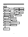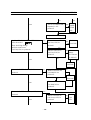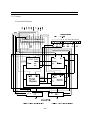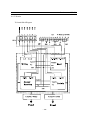
1
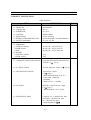
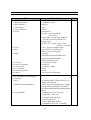
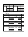
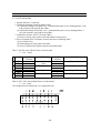
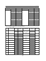
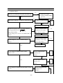
S/M No. : TSP110AEF0
Service Manual
Model : DSP-4210GM
CHASSIS : SP-110
DAEWOO ELECTRONICS CO., LTD
http : //svc.dwe.co.kr
May.2001
TABLE OF CONTENTS
1. Safety precautions ........................................................................................................................... 2
2. Product specification ...................................................................................................................... 4
3. Block diagram .................................................................................................................................. 6
4. Adjustment (How to use service remote controller) ..................................................................... 7
5. When changing the new board ....................................................................................................... 9
6. Trouble shooting .............................................................................................................................. 10
7. Assembly list ....................................................................................................................................30
8. Circuit diagram .................................................................................................................................31
9. Exploded view ..................................................................................................................................35
-1-
Service manual SP-110
1. SAFETY & PRECAUTIONS
SAFETY CHECK AFTER SERVING
Examine the area surrounding the repaired location for damage or deterioration. Observe that screw,
parts and wires have been returned to original positions. Afterwards, perform the following tests and
conform the specified values in order to verify compliance with safety standards.
1-1. Insulation resistance test
Confirm the specified insulation resistance between power cord plug prong and externally exposed
parts of the set (video and audio input terminals, speaker out terminals etc) is greater than values
given in table 1 below.
1-2. Dielectric strengthen test
Confirm specified dielectric strengthen between
power cord plug prongs and exposed accessible
parts of the set (video and audio input terminals,
speaker out, etc) is greater than values given
table 1 below.
1-3. Clearance distance
When replacing primary circuit component, confirm specified clearance distance (d), (d’) between
soldered terminals (see Fig1), and between terminals and surrounding metallic parts. See table 1
below.
Rating for selected areas (table 1)
AC Line Voltage
100V
110 to 130V
110 to 130V
200 to 240V
Region
Japan
USA &Canada
Europe
Australia
Latin America
Insulation
Resistance
Dielectric
Strength
Clearance
Distance(d),(d’)
3
3.2
6(d)
8(d)
(a : Power cord)
1M
/ 500V DC
-
1kV AC 1min.
900V AC 1min
10M
/ 500V DC
4kV AC 1min.
* Class model only
NOTE
This table is unofficial and for reference only. Be sure to confirm the precise values for your particular.
- 2 -
Service manual SP-110
1-4. Leakage current test
Confirm specified or lower leakage current between
B(earth ground, power cord plug prongs) and externally
exposed accessible parts (video and audio input terminals, speaker out, etc.)
Measuring method:(Power ON) lnsert load Z between
B(earth ground, power cord plug prongs) and exposed
accessible parts. Use AC voltmeter to measure AC voltage across both terminals of load Z. See Fig.2 and
following table.
Leakage current ratings for selected are as
Ac Line Voltage
Region
100V
Japan
110 to 130V
USA & Canada
Load Z
Leakage Current( i ) Clearance Distance(d),(d’)
i
1
1
i
15 F
110 to 130V
200 to 240V
Europe
Australia
50
Exposed accessible parts
0.5mArms.
Exposed accessible parts
0.7mA peak
2mAdc
i 0.7mA peak
i 1mAdc
i
2
1mArms.
i
Antenna earth terminals
Other terminals
NOTE
This table is unofficial and for reference only. Be sure to confirm the precise values
for your particular country and locality.
- 3 -
Service manual SP-110
2. PRODUCT SPECIFICATION
[ DSP-4210GM ]
ITEM
1. GENERAL
1-1. MODEL NO
1-2. CHASSIS NO
1-3. SCREEN SIZE
1-4. COUNTRY
1-5. RESOLUTION
1-6. REMOCON TRANSMITTER TYPE
1-7. SAFETY STANDARD
2. MECHANICAL
2-1. DIMENSION
1) WITHOUT STAND
2) WITH STAND
3) BOX
2-2. WEIGHT
1) WITHOUT STAND
2) WITH STAND
3. ELECTRICAL & OPTICAL
3-1. COMPOSITE VIDEO INPUT SIGNAL
SPECIFICATION
REMARK
DSP-4210GM
SP-110
42” (16:9)
WORLD WIDE
853(W) X 480(H)
R-V2A(ENGLISH), R-V2AK(KOREAN)
UL, CSA, CE, KE
W X H X D = 1055 X 652 X 85
W X H X D = 1055 X 730 X 85
W X H X D = 1190 X 870 X 480
33kg
39kg
NTSC,PAL,SECAM,PAL-M/N,NTSC4.43
1 INPUT ( 75 , 1Vp-p )
3-2. Y/C INPUT SIGNAL
50/60Hz, Super Jack 1 Input( 75
3-3. DTV/DVD INPUT SIGNAL
Y,Pb/Cb,Pr/Cr 1 Input
( 75 ,1Vp-p )
* DTV Resolution Mode ( Y, Pb, Pr ) :
1920X1080i, 1280X720p,
640X480p
* DVD ( Y,Cb,Cr ) : 50/60Hz
3-4. PC SIGNAL
R,G,B,H,V 15Pin D-sub jack 1 Input
( 75 ,1Vp-p )
* Resolution Mode : VGA - UXGA
3-5. SOUND INPUT SINAL
Composite, Y/C : L/R Phone Jack 1Pair
DTV/DVD : L/R Phone Jack 1Pair
PC : L/R Phone Jack 1Pair
* Input Impedance 47
- 4 -
,1Vp-p )
Service manual SP-110
ITEM
3-6. Optical Chracteristics
1) Display Resolution
2) Peak Luminance
3) Contrast Ratio
4) Color Temperature
3-7. Scaling
3-8. Zoom
3-9. PIP
3-10.OSD
3-11. AC Power
3-12. Power Consumption
3-13. Sound Output
3-14. LAN Interface
3-15. Settop Box Interface
3-16. Others
4. USER CONTROL & ACCESSORIES
4-1.CONTROL
1) SET
2) REMOCON TRANSMITTER
4-2. ACCESSORIES
SPECIFICATION
16:9 Wide 853 X 480
160cd/ m2
500:1
8000o K
<Scaling Mode>
PC, DTV : Fill to Aspect Ratio,
Fill to Screen
DVD, VIDEO : Normal, Wide, Panaroma,
Letter Box, Letter Box with Sub Title
<Scaling Adjust>
PC,DTV (User Control) : H-Size, V-Size
H-Position, V-Position
+
Zoom , 4Direction Paning Avaiable
Video Window in DTV/PC Picture
PIP Size, Position Changeable
8Language
KOREAN,ENGLISH,NETHERLAND,
FRENCH,SPANISH,GERMAN,
PORTUGUESE,ITALIAN
AC 90V-264V, 50/60Hz
350 WATTS
L : 8Watts, R : 8Watts
Option
Option
Freeze Picture, Video Rotation
AC POWER, MENU, INPUT SELECT, UP,
DOWN, LEFT, RIGHT
INPUT SELECT,POWER,RECALL, ZOOM-,
ZOOM+,MENU,UP,DOWN,LEFT,RIGHT,
PICTURE MODE,FREEZE,SCREEN MODE,
MUTE
1) REMOCON : R-V2A, R-V2AK
2) BATTERY : “AAA” 2EA
3) INSTRUCTION MANUAL
4) STAND (OPTION)
5) WALL HANGER (OPTION)
6) SPEAKER UNIT 2ASS’Y (OPTION)
- 5 -
REMARK
Service manual SP-110
3. BLOCK DIAGRAM
- 6 -
Service manual SP-110
4. Adjustment
4-1. How to confirm the origianl data of VIDEO PCB
(1) Input selection : You select video mode
(2) You confirm the original data of user control
- Brightness : 36 ( :20 in case of DTV/PC input mode )
- Contrast : 60
- Sharpness : 2
- Colour : 32
- Tint : 0 ( Center )
(3) You confirm the original data of SERVICE MODE (PW364)
( See 4-4 )
- Sub-Brightness : 60
- Sub-Contrast : 70
- R-Bias : 63
- G-Bias : 63
- B-Bias : 68
- R-Gain : 53
- G-Gain : 57
- B-Gain : 76
4-2. How to adjust POWER PCB
(1) Devices for measurement : Digital volt meter, Pattern generator
(2) Conditions : You adjust as follows after assembling set and inputting WHITE PATTERN.
1) VSUS(Sustain voltage) : Voltage sustaining electronic discharge
TP : P12
Adjustment control : RV600
Standard voltage : 166V
2) VSCAN(Scan voltage) : Scan voltage when recording DATA
TP : PA9 #6 PIN of Y PCB
Adjustment control : RV14
Standard voltage : -160V
3) VADD(ADDRESS voltage) : Voltage recording DATA
TP : P14
Adjustment control : VRS1
Standard voltage : 80V
4-3. X/Y PCB adjustment
(1) Devices for measurement : Digital volt meter, Pattern generator
(2) Previous adjustment voltage : You adjust as follows after assembling set and inputting BLUE
PATTERN.
- 7 -
Service manual SP-110
1) VSHELF(SHELF voltage) : X-electrode sustain voltage when recording DATA
TP : RCU25
Adjustment control : RU5
Standard voltage : +60V
2) VVH(SCAN VH voltage) : VH voltage of SCAN IC when scanning
TP : RY7 voltage each side
Adjustment control : RY6
Standard voltage : -70V
(3) The final operation adjustment
1) Input a monochrome pattern of R,G,B. And then you check if there are abnormal OFF-state
pixels (which must be in ON-state but are in OFF-state).
If any, increase VSUS voltage slowly from 166V to remove abnormal OFF state pixels in that
pattern.
2) If there is no abnormal OFF-state pixel in monochrome pattern of R,G,B, make sure if there is
abnormal OFF-state in Magenta, Cyan, Yellow or not. If any, increase VSUS slowly in that
pattern.
3) Increase VSUS, which is set as above, by 1V.
4) Make sure if there are abnormal ON-state pixels(which must be on OFF-state but are in ONstate, for example, R or G) in Blue pattern after aging Blue pattern 5 minutes. If any, set VSCAN
slowly from - 160V to - 150V and decrease VSHELF slowly to remove wrong electronic
discharge.
4-4. White balance adjustment
(1) Feed grey scale signal to video input terminal.
(2) Confirm the original data of user control (See 4-1).
(3) Press Remote controller in order starting with UP => MUTE => RECALL => MUTE BUTTON
to access Service adjustment
mode and select PW364. And then confirm the original data of
the Service mode PW364 register. (See 4-1).
(4) Make sure you can’t recognize any grey scale errors in the form of colour tint in this darker bands.
(5) You attach the sensor of a White balance meter to the white part on the upper end of this grey
scale pattern.
(6) Set White balance changing R,G,B-Gain.
• You make sure that R,G,B-Gain must be set within the limit of 63 20. If it is over the limit, it
is N.G.
• How to adjust temperature of colour
X = 0.290 0.01, Y = 0.310 0.01
Temperature of colour : 8,300o K
(7) You can set Luminance level changing Sub-contrast.
• If the set data of Sub-contrast is over the limit of 80, it is N.G.
(8) Press Menu button, to escape from Service mode.
- 8 -
Service manual SP-110
5. When fitting a new board
5-1. Video
(1) Check the related adjustments are correctly set as per previous page.
5-2. X-Sustain
(1) Set the VSHELF voltage according to the list of adjustments.
(2) The data of adjustment voltage is on the label, which is attached on the metal part under
Y-Sustain board.
5-3. Y-Sustain
(1) Set the Vvh voltage according to the list of adjustments.
(2) The data of adjustment voltage is on label, which is attached on the metal part under Y-Sustain
board.
5-4. Power module
(1) You set each voltage according to the list of adjustments.
(2) The data of adjustment voltage is on the label, which is attached on the metal part under
Y-Sustain board.
- 9 -
Service manual SP-110
6. Trouble shooting
6-1. Audio/video
6-2. Digital
6-3. X-SUSTAIN
6-4. Y-SUSTAIN
6-5. SCAN Board
6-6. DATA H/L, Connection(LU,CU,RU,LD,CD,RD)
6-7. Power
- 10 -
Service manual SP-110
6-1. Audio/Video
- 11 -
Service manual SP-110
* IMAGE PROCESSOR PART BLOCK DIAGRAM
- 12 -
Service manual SP-110
NO Video screen ( Composite input )
Check start
N
N
Does the ‘Please check input
signal or press “input” key.’
message appear?
Is there a weak electronic
discharge on the screen?
Y
1.Confirm AC connection
2.Confirm Power S/W on
3.Inspect Digital and X,Y
N
Y
Is the signal input jack
correctly connected?
1.Make sure of
connection of
Jack(PDP Monitor
& A/V device)
N
Y
N
Operate A/V device,
Which is used.
Does the input source operate?
Y
Is input selection in Video mode?
Y
Does the ‘DTV, PC’ screen
N
appear after inputting signal
to DTV or PC jack?
Y
is PA603 properly
connected?
Confirm Video to digital
Connector PA603
Y
is DVS,DHS,DCLK N Video PCB is N.G
of Video PCB P603
Change PCB
being outputted?
Y
1.Confirm other PCBs Video PCB than
2.Change PA603
N
Confirm
input selection
1. Video signal processing is N.G
2. Change video PCB
N
Can you see input to P502 No.43 V1
of Video PCB?
1. Inspect jack PCB
2. Inspect input jack
Y
Can you see input to TP Y0, V0?
Y
N
1. Video S/W and 3D COMB filter
(IC402) are N.G
2. Change video PCB
N
Can you output Sync of TP V2 : 60Hz/ 1. Confirm if IC400 and IC401
50Hz H2 : 31.5KHz/KHz?
are N.G
2. Change video PCB
Y
1. Video signal processing is N.G
2. Change Video PCB
CAUTION : 1.You must only remove PA603 after confirming
that you switch off the power.
2. You must thoroughly understand instruction manual
before removing Back cover.
- 13 -
Service manual SP-110
NO DTV screen (1080I, 720P, 480P)
Check start
N
Does the ‘Please check input
signal or press “input” key.’
message appear?
Y
Is the signal input jack
correctly connected?
1.Make sure of
connection of
Jack(PDP Monitor
& A/V device)
N
Y
N
Is there a weak electronic
discharge on the screen?
Y
N
is PA603 properly
connected?
N
Operate A/V device,
Which is used.
Does the input source operate?
Y
1.Confirm AC connection
2.Confirm Power S/W on
3.Inspect Digital and X,Y
Confirm Video to digital
Connector PA603
Y
is DVS,DHS,DCLK N Video PCB is N.G
of Video PCB P603
Change PCB
being output?
Y
1.Confirm other PCBs than Video PCBs
2.Change PA603
N
Is input selection in DTV/DVD mode?
Confirm
Y
input selection
Does the ‘Video’ screen
N
appear after inputting signal
1. DTV signal processing is N.G
to Video jack?
2. Change video PCB
Y
N
Can you see input to P502 No.10
YD1 of Video jack?
1. Inspect jack PCB
2. Inspect input jack
Y
Can you output DTV signal in
TP R,G,B?
N
Y
1. DTV S/W and DTV processor(IC505) circuit are N.G
2. DTV H/V Sync processing part is N.G
3. Change video PCB
N
Can you output Sync of TP V1:Hz/
H1 : KHz/ Hz?
1. DTV S/W and DTV processor
(IC505) circiuit are N.G
2. Change video PCB
Y
1. Video signal processing is N.G
2. AD Converter(IC500) is N.G
3. Change Video PCB
- 14 -
Service manual SP-110
NO PC screen
Check start
N
N
Does the ‘Please check input
signal or press “input” key.’
message appear?
Is there a weak electronic
discharge on the screen?
Y
1.Confirm AC connection
2.Confirm Power S/W on
3.Inspect Digital and X,Y
N
Y
1.Make sure of
connection of
Jack(PDP Monitor
& PC)
N
Is the signal input jack
correctly connected?
Y
N
Operate A/V device,
Which is used.
Does the input source operate?
Y
Does the ‘Video’ screen
appear after inputting signal
to Video jack?
Confirm
input selection
Y
Does DVS,DHS,DCLK N
of Video PCB P603
being output?
Y
N
1. PC signal processing is N.G
2. Change video PCB
Y
N
Can you see input to P502 No.9,8,31,32,33
R,G,B,Hsync,Vsync of Video PCB?
1. Inspect jack PCB
2. Inspect input jack
Y
N
Can you output PC signal in
TP R,G,B?
1. PC S/W and DTV processor(IC505) are N.G
2. PC H/V Sync processing part is N.G
3. Change video PCB
Y
N
Can you output Sync of TP V1 : Hz/
H1 : KHz/ Hz?
Confirm Video to digital
Connector PA603
Video PCB is N.G
Change PCB
1.Confirm other PCBs than Video PCB
2.Change PA603
N
Is input selection in PC mode?
Y
is PA603 properly
connected?
1. PC S/W is N.G
2.Change video PCB
Y
1. PC signal processing is N.G
2. A/D Converter is N.G
3. Change Video PCB
- 15 -
Service manual SP-110
NO Sound
Check start
Does the screen appear?
N
1. Confirm AC connection
2. Confirm power S/W on
3. Inspect video PCB and other blocks
Y
N
is the sound signal input jack
correctly connected?
1.Make sure of connection of jack(PDP monitor & A/V device)
Y
N
Connect speaker
is the speaker properly connected?
Y
N
1. Jack PCB is N.G
2. Video connection to
jack PCB is N.G
Is sound signal output from P502?
Y
is sound signal on P400 No.2,3
of audio PCB?
N
See: Siganl composition of P502 sound
1. RSPC, LSPC => PC sound
2. RSD1, LSD1 => DTV/DVD sound
3. RSV1, LSV1 => VIDEO, S-VHS sound
1. Sound S/W is N.G
2. Confirm IC404
3. Change video PCB
Y
is sound signal on PA400 No.2,4 N
of audio PCB?
1. PA400 connector is N.G
2. Change audio PCB
Y
is sound AMP on PA300 No.1,4 of
audio PCB processing an output?
N
Is power fed to PA3 of
audio PCB?
1. Confirm if PA3 connector is N.G
2. Change power board
Y
Y
Does sound AMP on PA300 No.1,4 and
JP659 of audio PCB produce an output?
N
N
1. PA300 is N.G (Change audio PCB)
or JP659 is N.G (Change jack PCB)
Y
1. Speaker or sound cable is N.G
2. Change speaker or sound cable
- 16 -
Service manual SP-110
NO Remote Controller operation
Check start
N
1. Confirm AC connection
2. Confirm power S/W on
3. Inspect video PCB, LED PCB and other
blocks
Is red LED next to POWER S/W
on?
Y
Does Remote Controller operate?
N
1. Confirm Remote Controller operation and battery
Y
Is screen on with key input?
N
1. Connection with video PCB is N.G or video PCB N.G
2. Inspect video PCB and other blocks
Y
Is there waveform when pressing remocon
in IR NO.2 of P602
N
1. LED PCB is N.G
2. Change LED PCB
1. IR receipt block of video PCB is N.G
2. Inspect video PCB and other PCBs
- 17 -
Service manual SP-110
NO Key operation
Check start
N
Is red LED on next to POWER S/W
on?
1. Confirm AC connection
2. Confirm power S/W on
3. Inspect video PCB, LED PCB and other
blocks
Y
Does power come on with
remocon?
N
Y
1. Connection with video PCB is N.G or
Video PCB is N.G
2. Inspect video PCB and other blocks
Is connection between PA601 of key PCB
and video PCB good?
N
1. PA601 connector is N.G
2. Change key PCB
Y
1. Inspect video PCB and other PCBs
- 18 -
Service manual SP-110
6-2. DIGITAL
Checking Order for normal operation of Digital Board and Check Points
( * Measure RMS voltage with a multi-meter, refer to the attached picture for position of
check points )
1. After make sure that the set turns off, turn off the High Voltage ON/OFF Switch of the Power
Board and then turn on the set
2. Confirm whether there is an input of 5V, 3.3V into Power Connector ( PA5 ).
- 5V input (pin No.1,2) : If 4.5V ~ 5.2V, O.K.
- 3.3V input (pin No.7,8) : If 3.0V ~ 3.5V, O.K.
3. Confirm whether Power 2.5V, 3.3V_1, 3.3V_2, 3V_3, 5V_1, 5V_2
- 2.5V : If 2.2V ~ 2.7V, O.K.
- 3.3V : If 3.0V ~ 3.5V, O.K.
- 5V : If 4.5V ~ 5.2V, O,K.
4. Confirm Reset and V_MUTE
- Reset : If 3.0V ~ 3.5V, O.K.
- V_MUTE :If 3.0V ~ 3.5V, O.K.
5. Confirm CONF_DONE ( ID102, ID103 )
- CONF_DONE : If 3.0V ~ 3.5V, O.K.
- 19 -
Service manual SP-110
- 20 -
Service manual SP-110
6-3. X-SUSTAIN BOARD
1. Separate PA7 and PA114 connector
2. Check the remaining electrical voltage of PA7
(1) Check the Voltage of Terminal 170V : If maintained beyond 10 volt, discharge (below 5 volt)
with resistance of beyond 1K ohm 5 Watt
3. Confirm the value of series and parallel resistance of RU10//RU13-RU11//RU14-RU12//RU15
(1) Each value of resistance : 6.8 ohm 5 Watt
(2) The total value of resistance : 10.2 +/- 0.5 ohm
(3) In case of wrong value of resistance, replace (open) board and confirm each connector
: the state of insertion ( installation )
4. In case of normal value of resistance, measure the value as following table1.
(1) Use a Diode Tester
(2) If abnormal part is found, replace the board
(3) In case of normal state, Inspect connectors and other boards
Table 1. PA7 The value of Diode Tester of each terminal
* + : red, - : black
NAME
1
170V
GND
DIODE
TESTER
+
-
2
15V
GND
+
-
3 CU1(5V)
GND
+
-
MEASURE
About 5 sec.
Later,
Open
About 3 sec.
Later,
Open beyond 2V
Beyond 1.43
DIODE
TESTER
+
MEASURE
+
0.47
+
0.48
Table 2. PA114 The value of Diode Tester of each terminal
* + : red, - : black
The configuration of terminal ( top view, components side )
- 21 -
0.49
Service manual SP-110
DIODE TESTER
+
GND
A
B
C
D
E
F
G
H
MEASURE
DIODE TESTER
+
GND
A
B
C
D
E
F
G
H
0.6
0.6
0.6
0.6
0.6
0.6
0.6
0.6
MEASURE
0.5
0.5
0.5
0.5
0.5
0.5
0.5
0.5
Table 3. The value of Diode Tester of each Semiconductor
* + : red, - : black
NAME
1
QU5/QU6
D
S
DIODE
TESTER
+
-
2
QU7/QU8
3
QU17/QU18
4
QU15/QU16
5
QU23~QU26
6
QU19~QU22
7
QU12
8
QU11
9
QU9
D
S
D
S
D
S
D
S
D
S
D
S
D
S
D
S
+
+
+
+
+
+
+
+
-
10
QU4
11
QU13/QU14
D
S
D
S
+
+
-
MEASURE
ABOUT 5
SEC. LATER,
OPEN
Open
Open
Open
Open
Open
Open
Beyond 2.3
ABOUT 5
SEC.LATER,
OPEN
Open
Open
- 22 -
DIODE
TESTER
+
MEASURE
+
+
+
+
+
+
+
+
0.48
+
+
0.48
0.45
0.45
0.4
0.4
0.49
0.49
0.5
0.5
0.48
Service manual SP-110
6-3. Y-SUSTAIN BOARD
1. Separate PA9, PA111 connector
2. Confirm the remaining electrical Voltage of PA9
(1) Confirm the Voltage of Terminal 170V : If maintained beyond 10 volt, discharge(below 5 volt)
with resistance of beyond 1K ohm 5 Watt
(2) Confirm the Voltage of Terminal -155V : If maintained beyond -10 volt, discharge(below -5
volt) with resistance of beyond 1K ohm 5Watt
3. Confirm the resistance of RY2 ( 470 ohm 5Watt )
(1) In case of wrong value, replace board and confirm each connector
4. In case of normal value of resistance, measure the value as following Table 1.
(1) Use a Diode Tester
(2) If abnormal part is found, replace the board
(3) In case of normal state, Inspect connectors and other boards
Table 1. PA9 The value of Diode Tester of each terminal
* + : red, - : black
NAME
1
170V
GND
2 -155V
GND
3 ON/OFF
GND
4
15V
GND
DIODE
TESTER
+
+
+
+
-
MEASURE
About 3 Sec. Later,
Open
Beyond 0.7
Open
Beyon 0.7
DIODE
TESTER
+
+
+
+
Table 2. PA111 The value of Diode Tester of each terminal
* + : red, -: black
The configuration of terminal (top view, components side)
- 23 -
MEASURE
Beyond 0.8
Open
Beyond 2.4
About 5 Sec. Later, beyond 0.4
Service manual SP-110
DIODE TESTER
+
GND
A
B
C
D
E
F
G
H
I
J
K
L
M
P
MEASURE
DIODE TESTER
+
GND
A
B
C
D
E
F
G
H
I
J
K
L
M
P
1.2
0.6
0.6
0.6
1.2
1.2
0.6
0.6
0.6
0.6
1.2
0.6
0.6
1.2
MEASURE
0.5
0.5
0.5
0.5
0.5
0.5
0.5
0.5
0.5
0.5
0.5
0.5
0.5
0.5
Table 3. The value of Diode Tester of each Semiconductor
* + : red, - : black
NAME
1
QY5~QY8
D
S
DIODE
TEST
+
-
2
QY9~QY12
3
QY1~QY2
4
QY3~QY4
5
QY25~QY28
6
QY20~QY23
7
QY15~QY16
8
QY19
9
QY14
10
QY13
11
QY2
D
S
D
S
D
S
D
S
D
S
D
S
D
S
D
S
D
S
D
S
+
+
+
+
+
+
+
+
+
+
-
MEASURE
ABOUT 3
SEC. LATER,
OPEN
Open
Open
Open
Open
Open
Open
Open
Open
Beyond 1
Open
- 24 -
DIODE
TEST
+
MEASURE
+
+
+
+
+
+
+
+
+
+
0.4
0.4
0.4
0.4
0.4
0.4
0.4
0.4
0.4
Open
0.4
Service manual SP-110
6-5. SCAN BOARD
1. Confirm the DIOED TESTER, PCB separately
2. The configuration
(1) The Voltage Terminal of Scan (top view, components side)
A
B
DIODE TESTER
+
-
MEASURE
Beyond 0.6
DIODE TESTER
+
- 25 -
MEASURE
Open
Service manual SP-110
6-6. DATA H/L, CONNECTION(RU,CU,LU,RD,CD,LD)
1. Confirm the upper part and the lower part
(1) Separate PA10 and PA11
(2) Confirm DIODE TESTER
2. Separate P112
(1) Confirm LU and two DATA H boards
3. Separate PA113
(1) Confirm CU and DATA H board
(2) Confirm RU and two DATA H boards
4. Separate P115
(1) Confirm LD and two DATA L boards
5. Separate P116
(1) Confirm CD and DATA L board
(2) Confirm RD and two DATA L boards
Table 1. The value of Diode Tester of each terminal
* + : red, - : black
1
2
NAME
Vadd
GND
5V
GND
DIODE TESTER
+
+
-
MEASURE
Open
Beyond
1.3
DIODE TESTER
+
+
- 26 -
MEASURE
0.6
0.5
Service manual SP-110
6-7. POWER CHECK
NO
When the set is switched on, the power LED turns red?
1. Check Fuse F1 open
2. Check RC 1(Bridge Diode)
open/short
YES
NO
When remote controller is switched on, LED turns green?
NO
Is 7PIN of CONNECTOR P2
Check
0 V?
VIDEO
PCB?
YES
Check R20, R21, R22 open
Push the SW1 (Slide switch) of POWER MODULE
in the opposite direction of
After P3 CONNECTOR is
separated, is each voltage
NO
Then, check LOW B+.
Is each voltage (30V, 12V, 5V) of CONNECTOR P3
(30V, 12V, 5V) correct?
correct?
Check Audio AMP PCB
YES
YES
Is each voltage(5V, 3.3V) of CONNECTOR P5
NO
After P5 CONNECTOR is
separated, is each voltage
NO
correct?
NO
(5V, 3.3V) correct?
YES
Check Digital PCB
YES
Is 1 pin voltage of CONNECTOR P7 and P9
correct at 15V?
NO
After P7 CONNCETOR is
YES
Check
X-sus
PCB
Separated, 15V
present?
NO
After P9 CONNCETOR is
Separated, 15V
YES
YES
Check
Y-sus
PCB
present?
NO
Is 1 pin voltage of CONNECTOR P10 and P11 correct
at 15V?
NO
After P10 CONNCETOR is
Separated, 15V
present?
YES
- 27 -
Service manual SP-110
YES
NO
Check
After P11 CONNECTOR is YES
CONNESeparated, is 15V
CTION
produced?
PCB
YES
Replace Power Module
Push the SW1(Slide Switch) POWER Module
NO
in the direction of
Then, check High Voltage
Without Connector P7
YES
Can Vsus(170V) be
producde?
And turn on the Power,
Can Vsus(170V) be produced?
Check
X-sus PCB
NO
Without Connector P9
Can Vsus(170V) be
YES Is the
Voltage
Of Conncetor
produced?
P7,5PIN 0V?
NO
YES
YES
Check
Y-sus PCB
Turn on the POWER. Can Vadd(70V) be
NO
produced?
Without Connector P10
Can Vadd(70V) be
produced?
NO
Check
Y-sus PCB
Without Connector P11
YES
Can Vadd(70V) be
produced?
Turn on the POWER. Can Vscan(-155V) be
produced?
YES
NO
NO
Without Connector P9
Can Vscan(-155V) be
YES
produced?
- 28 -
YES
YES
Check
Y-sus
PCB
NO
Service manual SP-110
NO
END
Replace
POWER
Module
- 29 -
Service manual SP-110
7. Assembly List
NO
PCB ASS’Y NAME
1
2
3
4
5
6
7
8
9
10
11
12
13
14
15
16
17
18
19
20
21
22
23
24
25
26
27
28
29
30
31
32
33
34
35
36
37
38
39
40
41
42
43
44
45
ACCESSORY AS
PACKING AS
CABINET AS
MASK FRONT AS
VIDEO PCB AS
WORKING PROCESS
ASS’Y NAME
ASSEMBLY
CODE
PEACPWD011
PEPKCPD011
PECACAD011
PEFMSJD011
PCB VIDEO MANUAL A
PCB VIDEO CHIP B AS
PCB VIDEO CHIP A AS
PEVDMSD011
PEVDJ2D011
PEVDJ1D011
PCB DIGITAL MANUAL
PCB DIITAL CHIP B
PCB DIGITAL CHIP A A
PCB DATA H AS
PCB DATA H CHIP A A
PEDGMSD011
PEDGJ2D011
PEDGJ1D011
PED1MSD011
PED1J1D011
PCB DATA L MANUAL
PCB DATA L CHIP A A
PED2MSD011
PED2J1D011
PCB SCAN MANUAL A
PCB SCAN CHIP A AS
PES1MSD011
PES1J1D011
PCB X-SUS MANUAL A
PCB X-SUS RHU AS
PCB X-SUS M-10 AS
PCB X-SUS RADIAL AS
PCB X-SUS CHIP A AS
PEXSMSD011
PEXSJ0D011
PEXSJBD011
PEXSJRD011
PEXSJ1D011
PCB Y-SUS MANUAL A
PCB Y-SUS RHU AS
PCB Y-SUS M-10 AS
PCB Y-SUS RADIAL AS
PCB Y-SUS CHIP A AS
PEYSMSD011
PEYSJ0D011
PEYSJBD011
PEYSJRD011
PEYSJ1D011
PCB AUDIO MANUAL A
PCB AUDIO RADIAL AS
PCB AUDIO AXIAL AS
PEAUMSD011
PEAUJRD011
PEAUJAD011
PCB JACK MANUAL AS
PEJAMSD011
PCB XSA MANUAL AS
PEXAMSD011
PCB UNION CHIP A AS
PCB UNION AS
PCB RIGHT-DO MANU
PCB RIGHT-DO A AS
PEUNJ1D011
PEUNSWD011
PERWMSD011
PERWJ1D011
DIGITAL PCB AS
DATA_H PCB AS
DATA_L PCB AS
SCAN PCB AS
X-SUS PCB AS
Y-SUS PCB AS
AUDIO PCB AS
JACK PCB AS
XSA PCB AS
CONN UNION
PCB AS
- 30 -
Service manual SP-110
8. Block Diagram
8-1. VIDEO / AUDIO
- 31 -
Service manual SP-110
8-2. Digital
- 32 -
Service manual SP-110
8-3. Y-Sustain
Y-Sustain Block Diagram
- 33 -
Service manual SP-110
8-4. X-Sustain
X-Sustain Block Diagram
·
·
·
·
·
·
- 34 -
686, AHYEON-DONG MAPO-GU
SEOUL, KOREA
C.P.O. BOX 8003 SEOUL, KOREA
TELEX : DWELEC K28177-8
CABLE : “DAEWOOELEC”
E-mail :[email protected]
TEL : 82-2-360-7806
FAX : 82-2-360-7877