1
Instruction Manual IM01005019E - Rev. 5
Eaton SPD Series
Surge Protective Device
For Integrated Units
Effective November 2013
Instruction Manual IM01005019E - Rev. 5
Effective November 2013
Eaton SPD Series
Surge Protective Device for Integrated Units
Table of Contents
1.0 Introduction .......................................................................................1
1.1 Manual Organization ...................................................................1
1.2 Product Overview .......................................................................1
1.3 Safety Precautions ......................................................................1
1.4 Catalog Numbering System ...................................................... 1
1.5 Equipment Testing ..................................................................... 2
2.0 Installation ........................................................................................2
2.1 Preparation for Installation ........................................................2
2.2 Installation Locations .................................................................2
2.2.1 Direct Bus Mount Applications .........................................2
2.2.2 Connected Through a Circuit Breaker Applications ....... 2
2.3 Installation Procedures ..............................................................2
2.3.1 Direct Bus Mount Applications .........................................2
2.3.2 Connected Through a Circuit Breaker Applications ....... 5
3.0 Operating Features .......................................................................... 6
3.1 General ........................................................................................6
3.2 Displays and Indicators ............................................................. 6
3.2.1 Basic Feature Package ...................................................... 6
3.2.2 Standard Feature Package ................................................ 7
3.2.3 Standard With Surge Counter Feature Package ............. 7
3.2.4 SPD Display Rotation.......................................................... 8
3.3 Remote Display Panel (RDP) Option ........................................ 8
3.4 IEC Approved Models................................................................. 8
4.0 Troubleshooting ............................................................................... 8
5.0 Specifications ....................................................................................10
6.0 Ordering Guidelines .........................................................................11
7.0 Warranty ............................................................................................ 12
Eaton is a registered trademark of Eaton Corporation or its subsidiaries and affiliates. National Electric Code and NEC are registered trademarks of the National Fire Protection Association. Power Chain Management is a registered trademark of Eaton Corporation, UL is a federally
registered trademark of Underwriters Laboratories, Inc. All other trademarks are property of their respective companies.
B
Eaton www.eaton.com
Eaton SPD Series
Surge Protective Device for Integrated Units
Instruction Manual IM01005019E - Rev.5
Effective November 2013
1.0 Introduction
WARNING
1.1 Manual Organization
This Installation Manual describes the safe installation, testing
and operation of the Eaton® SPD Series Surge Protective Device
(SPD).
ARC FLASH DURING INSTALLATION COULD CAUSE INJURY. USE
APPROPRIATE SAFETY PRECAUTIONS AND EQUIPMENT FOR ARC
FLASH PROTECTION.
This manual is organized into seven sections, as follows:
1.4 Catalog Numbering System
1.0 Introduction
2.0 Installation
3.0 Operating Features
4.0 Troubleshooting
Each Eaton SPD Series unit has a name plate that identifies
the parameters used for manufacture. These parameters are
expressed in letters and numbers, to reflect the Series, kA
Rating, Voltage Code, Feature Package, and Application.
5.0 Specifications
6.0 Ordering Guidelines
7.0 Warranty
Table 1. Catalog Numbering System
SPD 250 480D 2 J
1.2 Product Overview
The Eaton SPD Series protects critical electrical and electronic
equipment from damage by power surges. This is done by
shunting high energy lightning surges (and other transient disturbances) away from the equipment being protected. It does
this in nanoseconds by providing a low impedance surge path to
ground while supporting power frequency voltage.
The Eaton SPD Series is designed to mount on Panelboards,
Switchgear, Switchboards, Busway, and Motor Control Centers
(MCCs). It is available with surge current capacity ratings from
50 to 400kA.
The Eaton SPD Series is available in three feature packages (Basic, Standard, and Standard with Surge Counter), as
described in Section 3, "Operating Features." Each model is available in Delta, Wye, and Split Phase wiring configurations.
All Eaton SPD Series models have been tested and certified by
Underwriter’s Laboratory (UL®), to comply with UL Standard
1449, 3rd Edition.
Eaton’s One-Port low-voltage Surge Protective Device Wye
Models SPD120480Y2C, SPD160480Y2C, SPD200480Y2C
and Delta Models SPD120480D2C, SPD160480D2C,
SPD200480D2C meet the requirements of IEC 61643-11 / EN
61643-11, Part 11: Test Class II, and are intended to be installed
in indoor applications with a degree of protection rated IP 00.
Series
Voltage Code
kA Rating
Application
Feature Package
For example, a 480 volt Delta (3-wire plus Ground) for use in
an MCC application requires an SPD model SPD 250480D2J,
where:
SPD = SPD model,
250 = the kA rating (50 – 400 kA),
480D = the voltage,
2 = the feature package (Basic, Standard, Standard With Surge
Counter), and,
J = the Application Suffix (such as Direct Bus Mounted in a panelboard or Connected Through a Circuit Breaker).
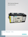
These numbers appear as part of the product label attached to
the front left side of the SPD. See Figure 1.
1.3 Safety Precautions
A licensed/qualified electrician must complete all instructions
in this manual in accordance with the National Electric Code
(NEC®), state, and local codes, or other applicable country
codes. All applicable local electrical codes supersede these
instructions.
WARNING
IMPROPER INSTALLATION COULD CAUSE DEATH, INJURY AND
EQUIPMENT DAMAGE. FOLLOW ALL WARNINGS AND CAUTIONS.
COMPLETELY READ AND UNDERSTAND THE INFORMATION IN THIS
INSTRUCTION MANUAL BEFORE ATTEMPTING TO INSTALL OR OPERATE THIS EQUIPMENT.
IMPROPER WIRING COULD CAUSE DEATH, INJURY AND/OR EQUIPMENT DAMAGE. ONLY LICENSED/QUALIFIED ELECTRICIANS WHO ARE
TRAINED IN THE INSTALLATION AND SERVICE OF ELECTRICAL SERVICES ARE TO INSTALL AND SERVICE THIS EQUIPMENT.
Figure 1. Product Label
HAZARDOUS VOLTAGES ARE PRESENT INSIDE THE SPD DURING
NORMAL OPERATION. FOLLOW ALL SAFE WORK PRACTICES TO AVOID
ELECTRICAL SHOCK.
Eaton www.eaton.com
1
Eaton SPD Series
Instruction Manual IM01005019E - Rev. 5
Surge Protective Device for Integrated Units
Effective November 2013
NOTICE
1.5 Equipment Testing
WARNING
CONDUCTING DIELECTRIC, MEGGER, OR HI-POTENTIAL TESTING
WITH THE SPD INSTALLED WILL CAUSE INTERNAL DAMAGE TO THE
SPD. THE SPD WILL ALSO CAUSE THE TEST TO FAIL.
Every Eaton SPD Series unit is tested at the factory for dielectric breakdown. No further SPD testing is required for installation.
If you desire to test distribution equipment by performing
dielectric, megger, or hi-potential tests, any installed SPD must
be disconnected from the power distribution system to prevent
damage to the unit.
Follow this procedure to safely disconnect the SPD:
1. Remove bus connected SPDs completely from the instal-
lation prior to performing any form of hi-potential testing.
2. Isolate SPDs connected via conductors as follows:
a. 3-wire delta SPDs: Turn off the circuit breaker to isolate the SPD, if connected through a circuit breaker.
b. Wye connected SPDs: Turn off the circuit breaker and remove the Neutral connection.
3. Remove MCC units with SPDs from the MCC structure.
A POOR GROUND, OR GROUNDING/BONDING VIOLATIONS, COULD
PREVENT THE SPD FROM PERFORMING AS SPECIFIED.
DO NOT USE THE SPD TO CARRY OR PASS THROUGH GROUND TO
OTHER DEVICES OR LEADS. DAMAGE TO THE EQUIPMENT MAY
RESULT.
•
Check the facility grounding system. All grounding, bonding,
and earthing must meet the NEC and any other national, state
and local electrical codes.
2.2 Installation Locations
Eaton's SPD Series can be installed directly to the bus for
Panelboard applications.
The SPD can also be connected through a circuit breaker for
installations in Panelboards, Switchboards, Switchgear, MCC’s
and Busway applications.
Follow these guidelines to determine the best location for
mounting this product.
2.2.1 Direct Bus Mount Applications
•
Install the SPD on the load side of the main breaker. Connect
the SPD directly to the bus located as close as possible to
the main breaker.
2.2.2 Connected Through a Circuit Breaker Applications
•
Install the SPD next to the first breaker after the incoming
main lugs or main breaker.
2.3 Installation Procedures
2.0 Installation
2.3.1 Direct Bus Mount Applications
WARNING
INSTALLING AN SPD THAT IS IMPROPERLY RATED FOR THE ELECTRICAL SYSTEM VOLTAGE COULD CREATE A POTENTIALLY HAZARDOUS
CONDITION, RESULTING IN INJURY OR EQUIPMENT DAMAGE.
2.1 Preparation for Installation
CAUTION
EATON SPD SERIES PRODUCTS MUST BE INSTALLED OR REPLACED
BY A QUALIFIED ELECTRICIAN TO AVOID INJURY OR EQUIPMENT
DAMAGE.
Before installing an Eaton SPD Series unit, do the following:
•
Verify that the area is clear of any dirt, debris or clutter that
may hamper the installation process.
•
Verify that there is enough space in the cabinet or MCC to
install the SPD. See Section 2.3, "Installation Procedures" for
dimensions.
•
Confirm that all tools and equipment needed for the installation are available.
•
Confirm that the system voltage and wiring configuration is
the same as the SPD you are installing. Check the voltage
rating label on the front left side of the SPD. See Figure 1.
1. Verify that the SPD you are about to install is rated for the application voltage and system. See Table 5 in Section 6, "Ordering Guidelines".
2. Follow all national, state and local electrical codes when con-
necting the SPD.
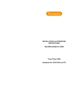
3. Before mounting the SPD, first determine the bus bar con- figuration. If the panelboard uses an offset B-Phase bus bar configuration, no action is required. If the panelboard uses a coplanar bus bar configuration, remove the bus bar extension bushing from the back of the SPD and discard. See Figure 2.
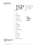
4. Mount the SPD to the support brackets (customer supplied) using #10 fasteners and tighten to 4.1 Nm (36 in-lbs). See Figures 4 and 5 for mounting details.
5. Install the bus mount fasteners and tighten to 4.1 Nm (36 in-lbs). See Figure 3.
WARNING
TURN OFF THE POWER SUPPLY BEFORE WORKING IN ANY ELECTRICAL CABINET OR ON ANY CIRCUIT BREAKER PANEL. FAILURE TO DO
SO COULD RESULT IN INJURY OR DEATH FROM ELECTRICAL SHOCK.
2
Eaton www.eaton.com
Figure 2. Bus Bar Extension Bushing
Eaton SPD Series
Instruction Manual IM01005019E - Rev.5
Surge Protective Device for Integrated Units
Effective November 2013
6. Select the correct wiring diagram for the SPD you are install-
ing. You must refer to this diagram while wiring the SPD. See Figures 6, 7, 8, and 9, on page 4.
Figure 3. Bus Connection
MOUNTING 8.80 [223.5]
4X MTG .19 [4.8]
BUS .34 [8.5]
.04 [1.0]
4.40 [111.8]
2.015 [51.2]
3X Ø.221
BUS MTG
2.015 [51.2]
.95 [24.0]
5.40 [137.0]
MTG 3.42 [86.9]
4.66 [118.4]
3.42 [86.9]
2.52 [64.0]
3.45 [87.7]
.26 [6.7]
3.42 [86.9]
TERMINALS 8.74 [222.0]
9.50 [241.3]
4X Ø.218 MOUNTING
4X #10-32 X .38 DP
BRASS TERMINALS
Figure 4. Dimensions for 50-200kA Units
MOUNTING 8.80 [223.5]
4X MTG 2.52 [63.9]
3.42 [86.9]
3.42 [86.9]
MTG 3.42 [86.9]
5.40 [137.0]
4.66 [118.4]
1.71 [43.5]
4.85 [123.1]
5.78 [146.8]
TERMINALS 8.74 [222.0]
9.50 [241.3]
4X Ø.218 MOUNTING
4X #10-32 X .38 DP
BRASS TERMINALS
Figure 5. Dimensions for 250-400kA Units
Eaton www.eaton.com
3
Instruction Manual IM01005019E - Rev. 5
Effective November 2013
Eaton SPD Series
Surge Protective Device for Integrated Units
Figure 6. Wiring - Single Phase Units (230 L)
Figure 8. Wiring - 3-Phase Delta Units
Figure 7. Wiring - Split Phase Units
Figure 9. Wiring - 3-Phase Wye Units
Figure 10. Wiring - High Leg Delta Units
NNote: Please consult the factory for 240 delta high leg (4W+G) applications with high leg on the 'C' Phase.
4
Eaton www.eaton.com
Eaton SPD Series
Surge Protective Device for Integrated Units
Instruction Manual IM01005019E - Rev.5
Effective November 2013
7. Connect the System Ground wire (green) to the SPD’s Surge Ground connection using a ring terminal suitable for use with a #10 fastener and a #10-32 x 3/8" fastener (customer supplied). Tighten the Surge Ground connection to 4.1 Nm (36 in-lbs). If the system uses an isolated ground, connect the isolated ground wire to Surge Ground. There are two Surge Ground connection points provided on the SPD. Connect only one of them. See Figure11.
Figure 13. Form C Connection
10.Install the dead-front panel to complete the installation.
2.3.2 Connected Through a Circuit Breaker Applications
Figure 11. Ground Connection
8. If equipped, connect the System Neutral wire (grey or white) to the SPD. Connect the System Neutral wire to the SPD’s Neutral connection using a ring terminal suitable for use with a #10 fastener and a #10-32 x 3/8" fastener (cus-
tomer supplied). Tighten the Neutral connection to 4.1 Nm (36 in-lbs). There are two Neutral connection points provided on the SPD. Connect only one of them. See Figure 12.
1. Verify that the SPD you are about to install is rated for the application voltage and system. See Table 5 in Section 6, "Ordering Gidelines".
2. Follow all national, state and local electrical codes when connecting the SPD.
3. Mount the SPD to the support brackets (customer sup-
plied) using #10 x 2-3/4" fasteners and tighten to 4.1 Nm (36 in-lbs). For 50-200kA models, see Figure 4 for mount-
ing dimensions. For 250-400kA models, see Figure 5 for mounting dimensions. Note: Mount the SPD as close as possible to the circuit breaker.
4. Determine the wire length required to connect to the breaker and cut Phase wires to the appropriate length. (To maximize SPD performance, wire length should be as short as possible). Note: For wire lengths longer than 4", Phase wires should be twisted once for each 4" of wire length to maximize SPD performance.
5. Connect Phase wire to circuit breaker. NEC requires that
conductors to a surge device be protected by an overcurrent protection device. The cables on the SPD are #10 AWG,
therefore would require a 30A 3-pole breaker. See Figure 14,
and the wiring diagrams shown in Figures 6, 7, 8 and 9.
Figure 12. Neutral Connection
9. The SPD (Standard and Standard with Surge Counter mod-
els) also has an available connection for remote monitoring of the Form C relay contacts. See Figure13. This is a green connector located on the side of the SPD. To make the con-
nection, remove the green connector and install the remote monitor leads (connector supports 12-24AWG wire). Fasten the remote monitoring wires to the N.O., N.C and COM connection points per the label on the front of the SPD. Contacts are rated: 150 Vac or 125 Vdc at 1A. Follow all national, state and local electrical codes. With wiring com-
plete, plug the green connector into the SPD.
Figure 14. Phase Connections
Eaton www.eaton.com
5
Instruction Manual IM01005019E - Rev. 5
Effective November 2013
6. Connect the System Ground wire (green) to the SPD’s Surge Ground connection using a ring terminal suitable for use with a #10 fastener and #10-32 x 3/8" fastener (customer supplied). Tighten the Surge Ground connec-
ion to 4.1 Nm (36 in-lbs). If the system uses an isolated
ground, connect the isolated ground wire to Surge Ground. There are two Surge Ground connection points provided on the SPD. Connect only one of them. See Figure 11.
7. If equipped, connect the System Neutral wire (grey or white) to the SPD. Connect the System Neutral wire to the SPD’s Neutral connection using a ring terminal suit
able for use with a #10 fastener and a #10-32 x 3/8" fas-
tener (customer supplied). Tighten the Neutral connec-
tion to 4.1 Nm (36 in-lbs). There are two Neutral connection points provided on the SPD. Connect only one of them. See Figure 12.
8. The SPD (Standard and Standard with Surge Counter models) also has a connection available for remote monitoring of the Form C relay contacts. See Figure 14. This is a green connector located on the side of the SPD. To make the connection, remove the green connector and install the remote monitor leads (connector supports 12-24 AWG wire). Fasten the remote monitoring wires to the N.O., N.C. and COM connection points per the label on the front of the SPD. Contacts are rated: 150 Vac or 125 Vdc at 1A. Follow all national, state and local electrical codes. With wiring complete, plug the green connector into the SPD.
Eaton SPD Series
Surge Protective Device for Integrated Units
2. Connect the RDP cable to the SPD. Use tie wraps (already on the SPD) to secure the cable to the SPD. See Figure 16. Cable can be routed as a right or left dress.
Figure 16. RDP to SPD Connection
3. Connect the RDP cable to the display. Use tie wraps (already on the RDP) to secure the cable to the RDP. See Figure 17.
9. The final step of the SPD installation depends on the spe-
cific application. The various applications are listed below by catalog suffix.
a. Suffix 'B': This is the Remote Display Panel (RDP) option. The RDP option requires the addition of a fac-
tory supplied RDP cable. See Section 3.3, "Remote Display Panel (RDP) Option" for Cable Catalog num-
bers.
1. Install the RDP using cutout and mounting dimen-
sions provided in Figure 15.
Figure 17. RDP Cable to Display Connection
b. Suffix 'C': This unit is intended for use in Panelboard, Switchboard, and Busway applications.
1. Ensure that the dead-front or door has the appro-
priate cut-out to accommodate the SPD Display. See Figure 4 or Figure 5.
2. Install dead-front or door and secure.
c. Suffix 'J': This unit is intended for MCC applications that require a NEMA 12 enclosure rating.
1. Ensure that the MCC bucket door has the appro-
priate cut-out to accommodate the SPD Display. See Figure 4 or Figure 5.
2. Place an appropriate NEMA 12 rated gasket around the Display opening on the inside of the door.
3. Install the door and secure.
Figure 15. RDP Cutout and Mounting
6
Eaton www.eaton.com
Eaton SPD Series
Instruction Manual IM01005019E - Rev.5
Surge Protective Device for Integrated Units
Effective November 2013
3.0 Operating Features
3.2.2 Standard Feature Package
3.1 General
The Eaton SPD Series Standard Feature Package display is
shown in Figure 19.
The Eaton SPD Series comes in three feature packages: Basic,
Standard, and Standard with Surge Counter. The operating specifics of each feature package are described below.
The Eaton SPD Series requires no operator involvement, other
than to monitor the display panel to determine status of the
SPD.
After system power is applied, the SPD automatically begins
protecting downstream electrical equipment from voltage transients.
Some SPD units have a Form C relay contact that allows for the
remote indication of SPD status. Form C contact wires are connected via a three terminal connector. See Figure 13.
3.2 Displays and Indicators
All Eaton SPD Series units (Basic, Standard, and Standard With
Surge Counter) use a display panel to indicate system status.
The display panel is slightly different for each feature package.
Figure 19. Standard Feature Package Display
Each display has both green and red light emitting diodes
(LEDs) to indicate the status of the protection on each phase.
Green indicates the phase is fully protected. Red indicates a
loss of protection. Wye, Split Phase and High-Leg Delta units
have an additional set of green/red LEDs to indicate status of
Neutral/Ground protection.
•
All features of the Basic Feature Package.
•
One Form C relay contact rated at 150Vac or 125Vdc @1A.
When the LEDs turn red, an audible alarm will also sound on
units equipped with an audible alarm.
The Standard Feature Package has the following features:
•
Normal operating conditions. N.O. = OPEN. N.C =
CLOSED.
•
Loss of protection on any phase or loss of power. N.O. =
CLOSED. N.C. = OPEN.
•
Audible alarm with Reset push button.
Specific operating conditions displayed for each Eaton SPD
Series Feature Package are described below.
•
EMI/RFI filtering.
3.2.1 Basic Feature Package
3.2.3 Standard With Surge Counter Feature Package
The Eaton SPD Basic Feature Package display is shown in
Figure 18.
The Eaton SPD Series Standard With Surge Counter Feature
Package display is shown in Figure 20.
Figure 18. Basic Feature Package Display
The Basic Feature Package has the following features:
•
•
Green LEDs: Illumination indicates the phase is fully protected, and operating normally, with all protection active and
available. Green LEDs also indicate Neutral to Ground protection on units with a Neutral wire. Green LEDs do not indicate
on/off status of power.
Red LEDs: Illumination indicates a loss of protection, and
that one or more protective devices are now inactive and
unavailable for that Phase. Red LEDs also indicate Neutral to
Ground protection on units with a Neutral wire. Red LEDs do
not indicate on/off status of power.
Figure 20. Standard With Surge Counter Feature Package
Display
The Standard With Surge Counter Feature Package has the following features:
•
All features of the Standard Feature Package.
•
LCD screen that displays surge count.
•
Reset button to RESET the surge counter to zero.
Eaton www.eaton.com
7
Instruction Manual IM01005019E - Rev. 5
Effective November 2013
Eaton SPD Series
Surge Protective Device for Integrated Units
3.2.4 SPD Display Rotation
3.3 Remote Display Panel (RDP) Option
The SPD display can be rotated on the SPD enclosure, up to 360
degrees. This allows you to position the display for the best visibility regardless of the position in which the SPD is installed.
The Eaton Series SPD displays may be monitored on a remote
display panel (RDP). This is indicated by the catalog style with a
'B' suffix (such as SPD250480D2B).
Rotations are at 90, 180, and 270 degrees.
A separately purchased RDP cable is required to connect the
SPD unit to the display.
For a typical horizontal mounting see Figure 21. For a typical vertical mounting see Figure 22.
Reposition the SPD display as follows:
1. Remove power from the unit.
2. Remove and discard the perforated overlay material at the two opposite corners of the display.
3. Remove the two phillips head screws that hold the display.
4. Rotate the display to the desired position. Be careful not to overstress the display ribbon cable.
5. Place the display back onto the SPD enclosure. Again, be careful not to overstress or crimp the ribbon cable.
6. Replace the two phillips head screws. Tighten screws to 1.35 Nm (12 in-lbs).
7. Restore power to the unit.
Table 2 lists these cables and their part numbers.
Table 2. RDP Cable Options
Description
Catalog No.
4 ft. Cable for RDP
8 ft. Cable for RDP
12 ft. Cable for RDP
SPDRDCAB04
SPDRDCAB08
SPDRDCAB12
3.4 IEC Approved Models
Eaton’s One-Port low-voltage Surge Protective Device Wye
Models SPD120480Y2C, SPD160480Y2C, SPD200480Y2C
and Delta Models SPD120480D2C, SPD160480D2C,
SPD200480D2C meet the requirements of IEC 61643-11 / EN
61643-11, Part 11: Test Class II, and are intended to be installed
in indoor applications with a degree of protection rated IP 00.
The SPD Delta and Wye Models are intended for use with a 3
Phase TN-S System with PE and Neutral Distribution, 5 conductor with a minimum 10 AWG or 6 mm2. The Delta Models are
also intended for use with a 3 Phase TN-C System with PEN
Distribution, 4 conductor with a minimum 10 AWG or 6mm2.
Screws used for connection to ground shall be #10-32 x 3/8”
and shall not be zinc or aluminum. This product is not serviceable and contains no replaceable parts.
Additional product information and ratings for IEC Applications:
−− The SPD contains internal disconnects with a short circuit
current rating ISCCR of 200kA.
Figure 21. Typical Horizontal Display Mounting
−− Residual Current IPE for this product is 5 mA.
−− Operating temperature is Normal -5°C to 40°C (23°F to
104°F.
−− Humidity range is 5% through 95% non-condensing.
−− The SPD may be mounted directly to earthed conductive
surface, installed as per this manual.
−− Temporary overvoltage rating UT = 402.6 V.
−− Withstand or safe failure mode, for tT = 120 minutes,
UT = 526 V.
−− Modes of protection as marked on a Wye SPD = L - L, L - N,
L - G(PE), N - G(PE).
−− Modes of protection as marked on a Delta SPD = L - L,
L - G(PE).
Figure 22. Typical Vertical Display Mounting
8
Eaton www.eaton.com
Eaton SPD Series
Surge Protective Device for Integrated Units
Instruction Manual IM01005019E - Rev.5
Effective November 2013
4.0 Troubleshooting
Many SPD failures result from improper installation. Once the
SPD is installed properly, it is a highly reliable unit.
If the SPD does not function properly, first confirm that it is
installed properly. See Section 2, “Installation.”
If the SPD malfunctions after it has been operating routinely,
refer to Table 3. This Troubleshooting Chart identifies possible
causes and solutions to the malfunction. Further assistance
may be obtained by calling Eaton’s Applications Engineers, at
1-800-809-2772, option 4, sub-option 2, including being directed
to the warranty process if applicable.
Table 3. Troubleshooting Chart
Condition
Probable Cause
Solution
Green LEDs ON (1 per phase) and one Green LED ON for
Neu/Gnd Protection
Normal operation
N/A.
Audible Alarm OFF, Form C (N.C.) contact in the CLOSED
state
Normal operation
N/A.
Phase Green LED is OFF, same Phase Red LED is ON,
Audible Alarm is ON
Phase protection compromised or lost
Replace SPD
Extended Temporary Overvoltage (TOV)
Check electrical system for TOV sources, correct,
replace SPD
Significant surge event
Replace SPD
Neu/Gnd Green LED is OFF, Neu/Gnd Red LED is ON,
Audible Alarm is ON (for models with Neutral connections)
Neu/Gnd protection is compromised or lost
Replace SPD
Significant surge event
Replace SPD
All phase Green LEDs OFF, all phase RED LEDs ON, Audible
Alarm is ON
All phase protection is compromised or lost
Replace SPD
SPD rated voltage is less than system voltage
Replace SPD with correct voltage model
Extended Temporary Overvoltage (TOV)
Check electrical system for TOV sources, correct,
replace SPD
Significant surge event
One of the display Red LEDs is ON. Audible Alarm is OFF
All Green and Red LEDs are OFF, LCD display (on Surge
Counter models) is OFF
Replace SPD
Audible Alarm Silence button has been depressed and
Alarm is silenced
Normal operation
SPD is not connected to a power source
Check system voltage at SPD connection
If power is cycled and a fault condition still exists, the
Audible Alarm will reactivate
Check SPD connections
Eaton www.eaton.com
9
Instruction Manual IM01005019E - Rev. 5
Effective November 2013
Eaton SPD Series
Surge Protective Device for Integrated Units
5.0 Specifications
Table 4. Specifications
Description
Specification
Surge current capacity per phase
50, 80, 100, 120, 160, 200, 250, 300, 400 kA ratings available
Nominal discharge current (In)
20kA
Short circuit current rating (SCCR)
200kA
SPD Type
Basic feature package = Type 1 (can also be used in Type 2 applications)
Standard and Standard with Surge Counter feature packages = Type 2
Standard split phase voltages available
120/240
Single phase
230
Three phase wye system voltages available
120/208, 127/220, 230/400, 277/480, 347/600
Three phase delta system voltages
240, 480, 600
Three phase high leg delta system voltages
120/240
Input Power Frequency
50/60 Hz
Power consumption (Basic units)
208Y, 220Y, 230L, 240S, 240D, and 240H voltage codes
0.5W
400Y and 480Y and 480D voltage codes
1.1W
600Y and 600D voltage codes
1.3W
Power consumption (Standard and Standard with Surge Counter units)
208Y, 220Y, 230L, 240S, 240D, and 240H voltage codes
0.6W
400Y, 480Y, and 480D Basic voltage codes
1.7W
600Y and 600D voltage codes
2.1W
Protection modes
Single split phase .....................L-N, L-G, N-G, L-L
Single phase .............................L-N, L-G, N-G
Three phase Wye...................... L-N, L-G, N-G, L-L
Three phase delta......................L-G, L-L
Three phase high leg delta........L-N, L-G, N-G, L-L
Maximum continuous operating voltage (MCOV)
208Y, 220Y, 240S, 240D, and 240H voltage codes
150 L-N,150 L-G, 150 N-G, 300 L-L
230L, 400Y and 480Y voltage codes
320 L-N, 320 L-G, 320 N-G, 640 L-L
600Y voltage code
420 L-N, 420 L-G, 420 N-G, 840 L-L
240 D voltage code
320 L-G, 320 L-L
480 D voltage code
640L- L-G, 640 L-L
600D voltage code
840 L-G, 840 L-L
Ports
1
Operating temperature
-40 through 50° C (-40 through 122° F)
Operating humidity
5% through 95%, non-condensing
Operating altitude
Up to 16,000 ft (5000 m)
Seismic withstand capability
Meets or exceeds the requirements specified in the IBC® 2006, CBC 2007, and UBC® Zone 4
Weight
50-200kA - Approximately 1.6 kg (3.5 lbs) – 250 - 400kA - Approximately 3.2kg (7.0 lbs)
Form C relay contact ratings
150 Vac or 125 Vdc, 1A maximum
Form C relay contact loogic
Power on, normal state - NO contact = OPEN, NC contact = CLOSED
Power off, fault state, - NO contact = CLOSED, NC contact = OPEN
EMI/RFI filtering attenuation (Standard and Standard With Surge Counter
Up to 50 dB from 10 kHz to 100 MHz
Agency certifications and approvals
UL1449 3rd Edition recognized component for the US and Canada, UL1283 (Type 2 SPDs only)
IEC 61643-11/EN 61643-11, Part 11: Test Class II. See Section 6.0 Ordering Guidelines for specific models.
Warranty
10 Years, 15 Years if the product is properly registered with Eaton.
10
Eaton www.eaton.com
Eaton SPD Series
Instruction Manual IM01005019E - Rev.5
Surge Protective Device for Integrated Units
Effective November 2013
6.0 Ordering Guidelines
Table 5. Eaton SPD Series
SPD 250 480D 2 J
SPD
kA Rating
Voltage Code
Options
50kA Per Phase
80kA Per Phase
100kA Per Phase
120kA Per Phase**
160kA Per Phase**
200kA Per Phase**
250kA Per Phase
300kA Per Phase
400kA Per Phase
Options
Integrated Units
240S = 120/240 Split Phase
208Y = 120/208 Wye (4W + G)
220Y = 127/220 Wye (4W + G)
400Y = 230/400 Wye (4W + G)
480Y = 277/480 Wye (4W + G)**
600Y = 347/600 Wye (4W + G)
240D = 240 Delta (3W + G)
480D = 480 Delta (3W + G)**
600D = 600 Delta (3W + G)
240H = 240 Delta High Leg (4W + G) on 'B' Phase
230L = 230 Single Phase*
NOTE: Please consult the factory for 240 Delta HIgh
Leg (4W+G) applications with high leg on 'C' Phase
* UL1449 3rd edition only
Feature Package
Application Suffix
Options
1 = Basic.
Dual colored LED per Phase to indicate Protection status
Dual colored LED to indicate protection status of the N-G Mode on
units with a Neutral Wire
2 = Standard.
Dual colored LED Per Phase to indicate Protection Status
Dual colored LED to indicate Protection Status of the N-G Mode on
units with a Neutral Wire
Audible alarm with Silence button
Form 'C' Relay Contact. See Table 4 Specifications
EMI/RFI filtering Providing up to 50dB of Noise Attenuation from
10KHz to 100Mhz
3 = Standard With Surge Counter
Dual colored LED Per Phase to indicate Protection Status
Dual colored LED to indicate Protection Status of the N-G Mode on
units with a Neutral Wire
Audible alarm with Silence button
Form 'C' Relay Contact
EMI/RFI filtering Providing up to 50dB of Noise Attenuation from
10kHz to 100Mhz Surge Counter with Reset Button
Options
Integrated Units
A = Panelboards, Direct Bus Mounted
B = Switchgear (Includes remote display panel & mounting hardware). Order cable
separately
C = Panelboards, Switchboards, Busway
J = Motor Control Centers
NOTE: Units used in Panelboard applications are available in
50 – 200kA ratings only
NOTE: Use the 'C' option for Panelboard Applications when
unit is connected through a Circuit Breaker
** Eaton’s Wye Catalog Numbers SPD120480Y2C, SPD160480Y2C, and SPD200480Y2C and Eaton’s Delta Catalog Numbers SPD120480D2C, SPD160480D2C, and SPD200480D2C
meet the requirements of IEC 61643-11/EN 61643-11, Part 11: Test Class II, and intended to be installed in indoor applications with a degree of protection rated IP 00.
Example: SPD 250480D2J = SPD Series, 250kA Per Phase, 480D Voltage, Standard Feature Package, Motor Control Center Application.
Eaton www.eaton.com
11
Instruction Manual IM01005019E - Rev. 5
Effective November 2013
7.0 Warranty
Eaton warrants these products for a period of 10 years from the
date of delivery to the purchaser , 15 years if the product is properly
registered with Eaton, to be free from defects in both workmanship
and materials. Eaton assumes no risk or liability for results of the
use of the products purchased from it, including but without limiting
the generality of the foregoing: (1) The use in combination with any
electrical or electronic components, circuits, systems, assemblies,
or any other materials or substances; (2) Unsuitability of any product
for use in any circuit or assembly.
Purchaser’s rights under the warranty shall consist solely of requiring Eaton to repair, or at Eaton's sole discretion, replace, free of
charge, F.O.B. factory, and defective items received at said factory
within said term determined by Eaton to be defective. The giving of
or failure to give any advice or recommendations by Eaton shall not
constitute any warranty by or impose any liability upon Eaton. The
foregoing constitutes the sole and exclusive liability of Eaton AND
IS IN LIEU OF ANY AND ALL OTHER WARRANTIES EXPRESSED,
IMPLIED OR STATUTORY AS TO THE MERCHANTABILITY,
FITNESS FOR PURPOSE SOLD, DESCRIPTION, QUALITY,
PRODUCTIVENESS OR ANY OTHER MATTER.
In no event shall Eaton be liable for special or consequential damages or for delay in performance of the warranty.
This warranty does not apply if the product has been misused,
abused, altered, tampered with, or used in applications other than
specified on the nameplate. At the end of the warranty period,
Eaton shall be under no further warranty obligation expressed or
implied.
The product covered by this warranty certificate can only be repaired
or replaced by the factory. For help on troubleshooting the SPD, or
for warranty information, call 1-800-809-2772, Option 4, sub-option
2. Repair or replacement units will be returned collect. If Eaton
finds the return to be a manufacturer’s defect, the product will be
returned prepaid.
Eaton SPD Series
Surge Protective Device for Integrated Units
Copyright © 2013 by Eaton, Moon Township, PA, USA. All rights
reserved. No part of this document may be reproduced in any way
without the express written approval of Eaton.
Specifications contained herein are subject to change without
notice.
EATON - CONFIDENTIAL AND PROPRIETARY NOTICE TO
PERSONS RECEIVING THIS DOCUMENT AND/OR TECHNICAL
INFORMATION IN THIS DOCUMENT, INCLUDING THE DRAWING
AND INFORMATION CONTAINED THEREON, IS CONFIDENTIAL
AND IS THE EXCLUSIVE PROPERTY OF EATON, AND IS MERELY
ON LOAN AND SUBJECT TO RECALL BY EATON AT ANY TIME.
BY TAKING POSSESSION OF THIS DOCUMENT, THE RECIPIENT
ACKNOWLEDGES AND AGREES THAT THIS DOCUMENT CANNOT
BE USED IN ANY MANNER ADVERSE TO THE INTERESTS OF
EATON, AND THAT NO PORTION OF THIS DOCUMENT MAY BE
COPIED OR OTHERWISE REPRODUCED WITHOUT THE PRIOR
WRITTEN CONSENT OF EATON. IN THE CASE OF CONFLICTING
CONTRACTUAL PROVISIONS, THIS NOTICE SHALL GOVERN THE
STATUS OF THIS DOCUMENT.
DISCLAIMER OF WARRANTIES AND LIMITATION OF LIABILITY
The information, recommendations, descriptions and safety notations in this document are based on Eaton's ("Eaton") experience
and judgment and may not cover all contingencies. If further information is required, an Eaton sales office should be consulted. Sale
of the product shown in this literature is subject to the terms and
conditions outlined in appropriate Eaton selling policies or other
contractual agreement between Eaton and the purchaser. THERE
ARE NO UNDERSTANDINGS, AGREEMENTS, WARRANTIES,
EXPRESSED OR IMPLIED, INCLUDING WARRANTIES OF
FITNESS FOR A PARTICULAR PURPOSE OR MERCHANTABILITY,
OTHER THAN THOSE SPECIFICALLY SET OUT IN ANY EXISTING
CONTRACT BETWEEN THE PARTIES. ANY SUCH CONTRACT
STATES THE ENTIRE OBLIGATION OF EATON. THE CONTENTS OF
THIS DOCUMENT SHALL NOT BECOME PART OF OR MODIFY
ANY CONTRACT BETWEEN THE PARTIES.
In no event will Eaton be responsible to the purchaser or user in
contract, in tort (including negligence), strict liability or otherwise
for any special, indirect, incidental or consequential damage or loss
whatsoever, including but not limited to damage or loss of use of
equipment, plant or power system, cost of capital, loss of power,
additional expenses in the use of existing power facilities, or claims
against the purchaser or user by its customers resulting from the
use of the information, recommendations and descriptions contained herein.
Eaton
Electrical Sector
1000 Eaton Boulevard
Cleveland OH 44122
United States
1-800-809-2772, option 4, sub-option 2
Eaton.com
© 2013 Eaton
All Rights Reserved
Printed in USA
Publication No. IM01005019E TBG000335
November 2013
Eaton is a registered trademark.
All other trademarks are property of their
respective owners.