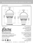
1
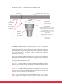
THE THERMAL EQUALIZER
OPERATING AND INSTALLATION MANUAL
FOR MODELS 10, 15 & 25.
OPERATING AND INSTALLATION MANUAL
1. Technical information
2. Warranty and Refurbish Program
3. Exploded view of the AIRIUS SYSTEM ®
4. General Installation and Operating guidelines
5. Hanging the AIRIUS SYSTEM
6. Placement of the AIRIUS SYSTEM
7. Suspended Ceiling Kit Assembly Instructions
8. Safety Information and Warnings
IMPORTANT
THIS MANUAL MUST BE READ CAREFULLY AND FULLY BEFORE ATTEMPTING TO
HANG, FIT, OR OPERATE AN AIRIUS SYSTEM
MODELS 10, 15, 25
USA and FOREIGN PATENTS PENDING
AIRIUS SYSTEMS are extremely efficient, quiet and unobtrusive Air Turbines that destratify and balance room temperature, generating a narrow vertical air column which
conditions the room environment and reduces the energy consumption of an HVAC
system by as much as 35%.
1. TECHNICAL INFORMATION
The AIRIUS SYSTEM is produced in three single-phase voltages: 120 VAC, 230 VAC,
and 277 VAC. Within each voltage there are multiple fan motor wattages. These
different wattages produce varying RPM (Revolutions Per Minute) and the different
RPM produce different rates of air flow to accommodate different heights from which
the AIRIUS SYSTEM system will be installed in the ceiling. The heights are identified
by the Model Number in Feet (10 feet = 3 Meters)
1
MODEL NUMBER - SERIAL NUMBER - MANUFACTURE INFORMATION
ELECTRICAL INFORMATION HAZARD INFORMATION IS LOCATED ON LABELS AT
THE EXAUST END OF THE APPLIANCE (THE MOTOR IS THERMALLY PROTECTED)
Model No.@120 VAC
= Motor Part No.
Hertz
Model 25 (7.6M)
Model 15 (4.6M)
Model 10 (3.0M)
= FP-108 HH (S1 B) - 50/60 Hz 30/35 W - 1500/1650 rpm
= FP-108 HH (S2 B) - 50/60 Hz 14/17W - 1100/1250 rpm
= FP-108 HH (S3 B) - 50/60 Hz 13/15W - 900/1080 rpm
Model No.@230 VAC
= Motor Part No.
Model 25 (7.6M)
Model 15 (4.6M)
Model 10 (3.0M)
= FP-108 HH (S1 B) - 50/60 Hz 31/35 W - 1500/1650 rpm
= FP-108 HH (S2 B) - 50/60 Hz 15/17W - 1100/1250 rpm
= FP-108 HH (S3 B) - 50/60 Hz 12/13W - 900/1080 rpm
Model No.@277 VAC
= Motor Part No.
Model 25 (7.6M)
= FP-108 HH (S1 B) - 50/60 Hz 34/42 W - 1500/1650 rpm
Hertz
Hertz
Wattage RPM
Wattage RPM
Wattage RPM
AIRIUS SYSTEM (Each Unit)
Weight - 12 LB (5.4 kilo)
Height - 22 inches (56 cm)
Max Diameter - 13 inches (33 cm)
The AIRIUS SYSTEM has an Outer Shell of Recyclable PC/ABS plastic resin
(Polycarbonate/Acrylonitrile Butadiene Styrene). The Inner Stator is also Recyclable
ABS. The Outer Shell, Stator and Fan Blade are Fire Rated 5VA Materials
(see exploded view - 1, next page).
2. WARRANTY
3 Year Warranty:
Free replacement unit - new. Customer or Distributor to return defective units to
AIRIUS Europe Ltd carriage paid. Upon receipt, AIRIUS Europe Ltd will despatch new
units by return carriage paid.
2
3. EXPLODED VIEW
Voltages - 120 VAC, 230 VAC, 277VAC. Total Height 22” (55.88cm) Width 13” (33.02 cm) Total Weight = 12lb (5.4k)
Image not available online.
The above graphic contains all the descriptions/components of the AIRIUS SYSTEM
models 10, 15, 25
Note: ALL SCREW SIZES ARE ENGLISH THREAD with TORX ¤ HEADS
ENGLISH SIZED HEX WRENCHS CAN BE SUBSTITUTED TO OPERATE SCREWS
4. INSTALLATION/OPERATING GUIDELINES
(For installation information please refer to the ‘Installation Guide’ which can be found
on the Airius website - www.airius.co.uk)
POWER CORD
The power cord is a 3 wire 18 AWG (or 16AWG) 300 VAC rated electrical cord
UL rated in North America (NA) as SJT or for CE/EU compliance rated as HO5VV
The three wires in the power cord are color coded to insure proper wiring as follows:
BLACK or BROWN = HOT/ELECTRIFIED/LIVE
WHITE or BLUE = “N” NEUTRAL/RETURN PATH
GREEN or YELLOW-GREEN = GROUND/EARTH
The cord is attached to the Fan Motor via two power leads with insulated 1 /4 “ quick
connects.
UNMARKED motor lead - HOT/LIVE
MARKED “N” motor lead - NEUTRAL
GROUND/EARTH is attached to a boss on the outside of the motor housing with a Star
Ring # 10 Terminal and 8-32 x 1 /4 “ machine screw.
The Cord is secured in the housing by a strain relief and knotted inside the housing for
additional security.
3
OUTLET - 120 VAC, 230 VAC and 277 VAC
Power Outlets (Female Connectors) to supply power to the AIRIUS SYSTEM should
always be installed by a qualified electrician or similarly qualified person in
accordance with national and local electrical codes.
The AIRIUS SYSTEM uses very little AMPERAGE (less than 1 amp) thus multiple outlets
may be installed on one circuit. Outlets are available in many configurations, check
with the local Electrical Contractor to determine preferred type for the facility. Outlets
should generally be mounted vertically unless a “twist/locking” type is being used.
Facilities with Fire suppression systems installed often have a master cutoff switch to
Shut-off all power in the event of a fire or emergency. The electrical circuits for the
AIRIUS SYSTEM should be wired through that Shut-off. Always use and review the
National / Local Electrical Codes when installing the AIRIUS SYSTEM in ANY Facility.
DO NOT wire the AIRIUS SYSTEM into the Lighting circuit, as the system will cycle
on and off with the lights, greatly reducing the systems effectiveness.
The AIRIUS SYSTEM is designed to operate 24 Hours-a-Day, 7 Days-a-Week (24/7) for
the maximum results.
PLUG - 120 VAC, 230 VAC and 277 VAC
120 VAC cord is supplied with a molded three prong polarized /grounded plug
DO NOT DEFEAT this SAFETY DEVICE or modify the plug in any way.
230/277 VAC (International market) no plug supplied. When fitting a plug always
ensure that all relevant local regulations/electrical codes are understood and followed
with care - if in any doubt seek expert guidance.
Procedure for Wiring the Plug in a Single-Phase Electrical System
Use CAUTION when wiring/attaching the Plug (Male Connector) to the AIRIUS
SYSTEM or when using any Electrical Device.
1.
2.
3.
4.
5.
Plug should be rated for 230 VAC (277VAC) or greater and fit properly
into Outlet (Female Connector) being used to deliver power.
To avoid electrical shock, DO NOT plug device into Energized Outlet
until all exposed wires, and connecting terminals, are enclosed by
Plug Housing. See Plug Manufacturer's Instructions.
Locate the (3) stripped wires on the 300 VAC Rated Power Cord
attached to the AIRIUS SYSTEM where the outer cord insulation
jacket has been removed. Wires are coded as follows:
Brown or Black is HOT/Positive/LIVE (the energized/electrified
conductor) Blue or White is Neutral “N” (the conductor used for a
return current path) Yellow-Green or Green is Ground/Earth (the
conductor to connect to the Earth)
Using the Plug Manufacturer's Instructions, Locate the proper
positions to attach the color-coded wire to the color-coded or
otherwise appropriately labeled terminals on the Plug.
Tighten all connections. Re-assemble plug in accordance with Plug
Manufacturer's Instructions.
4
Always hold the AIRIUS SYSTEM unit by the Bail/Crosspiece to avoid injury from
moving parts.
To confirm electrical continuity, if possible, Plug the AIRIUS SYSTEM into a energized
outlet, similar to the outlet installed in the ceiling, on the ground before permanently
mounting the AIRIUS SYSTEM in the ceiling.
NOTE: The AIRIUS SYSTEM can be wired directly to a junction box but only by a
qualified electrician or similarly qualified person. Always ensure that all relevant local
regulations/electrical codes are understood and followed with care - if in any doubt
seek expert guidance. Check Local Electrical Codes. The preferred system is designed
with a plug for easy service and cleaning (see Cleaning). An On-Off switch must be
installed in the circuit to be able to disable the power to prevent electrical hazard
when servicing the appliance.
BAIL aka: HANDLE or CROSS-PIECE
The BAIL is attached with two 1 /4 ” x 20 x 1” TORX® head machine screws. The screws
can be loosened to adjust the bail to the vertical so that it can be suspended from the
ceiling on the provided Eyebolt.
The Eyebolt is installed through a 5 /16 ” hole in the bail with locking nuts and washers.
NOTE: The Bail may be angled, as it is ratcheted for special situations where a vertical
air column is undesirable and an angled column would be more effective.
5. HANGING THE AIRIUS SYSTEM
The AIRIUS SYSTEM is designed to be hung vertically as high in the ceiling of the
facility as possible with the nozzle pointing to the floor for maximum thermal
equalization.
The AIRIUS SYSTEM is designed to hang vertically and freely from the ceiling on
professionally installed hardware, capable of supporting a minimum of four times the
weight, 12 lb (5.4 Kilo) of the AIRIUS SYSTEM unit. Example - 1 /4 ” (7mm) diameter
steel bolt is rated at 60 lb (27 Kilo) Load.
A feature of the AIRIUS SYSTEM is its flexibility. Hardware that may be used to hang
the unit includes, but is not restricted to: Hooks, chains, cables, carabineers, bridal
rings, beam clamps and bolts. Roof structure, building construction, electrical
outlets/service, and accessability will define the appropriate hardware for each
installation.
After insuring the AIRIUS SYSTEM is firmly attached and after REMOVING YOUR
HANDS FROM THE UNIT, ONLY THEN is it safe to plug the unit in to the power
source using the approved plug to confirm function and connectivity.
NOTE: SECURE the power cord to the ceiling structure as added security. The Cord will
act as a safety leash and by securing it the possibility of the plug accidentally coming
out of the outlet in the future is greatly reduced. A 50 lb (20 Kilo) rated Zip-T, several
wraps of electrical tape, or mechanics wire are examples of methods of securing the
5
power cord.
The following graphic is an example of the typical AIRIUS SYSTEM:
THE AIRIUS SYSTEM HANGING/MOUNTING GUIDELINES
Locking nuts, washers or beam clamp
Cord Secured
RSJ or Ceiling Beam
Intake
Receptical Rated
120 or 230 VAC
(277 VAC)
Swivel
FOR BEST EFFICIENCY
The AIRIUS SYSTEM should be securely installed as
close as possible to the ceiling. The AIRIUS
SYSTEM air column should have an unobstructed
passage to the floor.
The AIRIUS SYSTEM should not be mounted
directly in front of heat ducts, vents or near any
high heat source.
Twist Lock Plug
300 VAC Cord
Furnished
60lb (27 k)
Minimum rated
steel hook W/Latch
bridal ring or chain
AIRIUS SYSTEM
W/Eyebolt
CAUTION:
Unprotected
moving blades
MAXIMUM SPACING 1 UNIT PER 1000 sq ft
(100 sq m) 40 ft diameter circle (12 m)
Exhaust
The AIRIUS SYSTEM
weighs 12 lb (5.5 k)
Height 22” (56 cm)
Diameter 12” (31 cm)
6. PLACEMENT OF THE AIRIUS SYSTEM
The AIRIUS SYSTEM performs best when installed such that the air stream/exhaust
from the nozzle is unimpeded to the floor. This will insure maximum circulation and
Thermal Equalization. Each System is designed to cover approximately 1200 Sq Feet
(100 Sq M) from its designed ceiling height, which is about a 40-Foot (12 M) diameter
circle. The density of the placement is a direct relationship to effectiveness,
performance and savings.
Floors plans, mezzanines, office location, machinery, people placement, plumbing,
lighting systems, duct work, electrical systems, natural light/air systems, indoor cranes,
doors, windows, ventilation and fire suppression systems are all factors in properly
locating the AIRIUS SYSTEM in the ceiling.
Floor Plans - Sketch out the floor plan of the facility, divide it graphically into 1200 sq
ft (100 Sq M) squares and as closely as possible place an AIRIUS SYSTEM in the center
of each square of the grid. Adjust placement to accommodate.
Mezzanines - The AIRIUS SYSTEM can be hung at an angle to throw accumulated heat
out to a larger space, or hang the AIRIUS SYSTEM near the mezzanine out in the larger
space to remove heat and balance room temperature.
Office - Use smaller models to control individual office spaces, or larger units to
control common areas, eliminate hot and cold spots, create circulation, eliminate
electrical space heaters and reduce employee temperature related issues.
6
Machinery - Machinery and work processes that are sensitive to temperature change
will operate much more efficiently when the AIRIUS SYSTEM is operating. The flow of
air should be directed to a place that will allow circulation but not interfere with the
production process.
People - Most people are not comfortable in direct air flow, therefore the AIRIUS
SYSTEM can be directed to a space near the person, but not directly on them. This
balanced, equalised air will provide a better working environment.
Check local codes for plumbing, lighting systems, duct work, electrical systems as the
AIRIUS SYSTEM must not interfere with other systems and these systems should not
interfere with the airflow.
DO NOT mount the AIRIUS SYSTEM directly in front of or over a heat source.
Natural lighting/air systems (sky lights, ceiling vents) - DO NOT mount the AIRIUS
SYSTEM where it can get wet or be exposed to long-term moisture. Mounting the
AIRIUS SYSTEM in a high sealed sky light is an excellent way of recovering heat.
Indoor cranes and other ceiling mounted machinery - DO NOT interfere with the
function of these machines. When hanging the AIRIUS SYSTEM above these machines
it will not interfere with their operation.
Doors, Windows, Ventilation - The AIRIUS SYSTEM can reduce: drafts, fogging and
heat loss. However The AIRIUS SYSTEM cannot over come the accumulated effects of
not controlling the opening and closing of these portals. DO NOT mount the AIRIUS
SYSTEM directly in front of a window or vent that is always open unless cooling is the
desired result.
7. AIRIUS SYSTEM SUSPENDED CEILING KIT ASSEMBLY INSTRUCTIONS
Models 10, 15, 25 TOOLS REQUIRED - PHILIPS SCREW DRIVER
1.
2.
3.
4.
5.
6.
Remove all components from packaging materials. Using the box the
AIRIUS SYSTEM arrived in, open end up and place the 2 x 2 flat AIR
INTAKE GRID over the open end of the box face down.
Insert the AIRIUS SYSTEM into the center hole so that the nozzle
extends below the AIR INTAKE GRID and the power cord is hanging
over the edge.
Place DOME over AIRIUS SYSTEM and align it with the screw holes.
Note cutout for power cord on Dome edge. Dome should seat
into the rim designed for it on the base, if necessary gently push the
dome edge in until it seats into the lip.
Insert the Four (4) Philips screws 10/32 x 5/8 (provided) into the holes
and tighten, DO NOT force screws, as galling or stripping will occur.
Inserts are brass, screws will go in easily when aligned properly.
The Base is designed to replace a 2 x 2 ceiling tile. If replacing a 2 x
4 tile please use an additional piece of 2 ft T-bar suspension
material to finish the edge. This will provide additional strength and
rigidity to the existing suspension system.
The Base has Four Tabs located at each corner that can be drilled for
additional ceiling support wires to be added if desired.
7
8. THE AIRIUS SYSTEM SAFETY INFORMATION AND WARNING!
EACH AIRIUS SYSTEM HAS A POLARIZED/GROUNDED PLUG TO REDUCE THE
RISK OF ELECTRICAL SHOCK (NOT FITTED ON UNITS SENT TO EUROPE/MIDDLE
EAST - SEE WIRING INSTRUCTIONS). THIS PLUG CAN ONLY FIT INTO THE
DESIGNED POLARIZED/GROUNDED OUTLET ONE WAY. IF THE PLUG DOES NOT
FIT FULLY IN THE OUTLET, CONTACT A QUALIFIED ELECTRICIAN. DO NOT
ATTEMPT TO OVERCOME THIS SAFETY FEATURE.
WARNING!
•
UNPLUG UNIT FROM POWER SOURCE BEFORE YOU MOVE UNIT,
SERVICE UNIT, OR REMOVE HOUSING.
WARNING!
•
•
•
•
•
•
•
TO PREVENT ELECTRICAL SHOCK AND/OR INJURY:
TO REDUCE THE RISK OF FIRE OR ELECTRICAL SHOCK:
DO NOT USE THIS PRODUCT WITH ANY SOLID-STATE SPEED CONTROL
DEVICE.
DO NOT CARRY THIS PRODUCT BY THE CORD.
DO NOT USE THE CORD AS A HANDLE.
DO NOT USE THE CORD TO ATTACH OR HANG THE PRODUCT.
BE SURE TO GRASP THE PLUG, NOT THE CORD, WHEN DISCONNECTING
THIS UNIT FROM AN ELECTRICAL OUTLET.
DO NOT USE THIS PRODUCT IF IT HAS A DAMAGED CORD, FAULTY
PLUG, OR ANY BROKEN HOUSING COMPONENTS.
IF THE SUPPLY CORD, PLUG, OR HOUSING IS DAMAGED, IT MUST BE
REPLACED BY THE MANUFACTURER, ITS SERVICE AGENTS OR SIMILARLY
QUALIFIED PERSONS TO AVOID A HAZARD.
TO PREVENT DAMAGE, WHICH MAY RESULT IN FIRE OR SHOCK HAZARD:
•
•
•
•
•
•
•
•
•
•
DO NOT EXPOSE THIS PRODUCT TO RAIN OR DIRECT MOISTURE.
DO NOT IMMERSE PRODUCT INTO WATER.
DO NOT ALLOW WATER TO DRIP INTO THE MOTOR HOUSING.
DO NOT INSTALL OUTDOORS OR IN AN AREA OPEN TO THE WEATHER.
SHUT-OFF POWER TO A WET MOTOR AT SOURCE BEFORE SERVICING.
SPINNING BLADES MAY INFLICT EYE OR PHYSICAL INJURY.
ALWAYS REPLACE A DAMAGED BLADE.
DISCONNECT UNIT FROM POWER SOURCE FIRST.
CONTACT MANUFACTURER OR ITS AGENT FOR REPLACEMENT BLADES.
BLADES ARE BURN RATED 5VA FOR SAFETY.
CAUTION!
SOME AIRIUS SYSTEM PRODUCTS HAVE AN UNGUARDED
IMPELLER/FAN BLADE:
•
•
DO NOT USE THESE PRODUCTS IN LOCATIONS READILY ACCESSIBLE TO
PEOPLE OR ANIMALS, AS BLADES MAY INFLICT INJURY WHEN MOVING
OR STATIONARY.
TO REDUCE THE RISK OF INJURY TO PERSONS, INSTALL PRODUCT SO
THAT BOTTOM OF MOVING FAN BLADE OR THE LOWEST MOVING PART
IS AT LEAST 8.2 FT (2.5 METERS) ABOVE THE FLOOR OR GRADE LEVEL.
8
THE MOTOR IS THERMALLY PROTECTED; OVERHEATING (230F/110C) WILL CAUSE
THE MOTOR TO STOP OPERATING. THE MOTOR MAY RESTART ONCE NORMAL
OPERATING TEMPERATURES (195F/90C) ARE ACHIEVED. IF MOTOR FAILS TO
RESTART:
•
DISCONNECT MOTOR FROM ELECTRIC SOURCE AND CONTACT
MANUFACTURER OR ITS AGENT
DO NOT POSTION SYSTEM NEAR:
•
•
•
•
FURNACES, FIREPLACES, STOVES, OR OTHER HIGH TEMPERATURE HEAT
SOURCES.
DO NOT POSITION PRODUCT UNDER INFRA-RED HEAT SOURCES.
DO NOT POSITION THE UNIT CLOSE TO OTHER OBJECTS THAT WILL
INTERFERE WITH FAN OPERATION.
DO NOT ALLOW FAN BLADES TO COME INTO CONTACT WITH OTHER
OBJECTS.
SERVICE AND INSTALLATION!
NO LUBRICATION IS REQUIRED AS BEARINGS ARE SEALED. BAIL ADJUSTMENT
CAN BE MADE WITH A T-30 TORX DRIVER/WRENCH, OR A 5/32” HEX WRENCH
MAY BE USED. OTHER TOOLS - T-20 (7/64 H) & T-25 (1/8 H) TORX.
THE AIRIUS SYSTEM IS DESIGNED TO BE USED WITH ONLY THE ELECTRICAL
VOLTAGE IDENTIFIED ON THE LABEL. THIS CAN BE LOCATED IN THE NOZZLE
AND ON THE BOTTOM OF THE MOTOR, ANY OTHER VOLTAGE COULD DAMAGE
THE MOTOR AND CREATE AN ELECTRICAL HAZARD.
ASSEMBLING SUSPENDED CEILING KIT: SEE ADDITIONAL INSTRUCTIONS FOR
UNIT INCLUDED WITHIN THIS MANUAL.
IMPORTANT!
•
•
•
•
PLEASE INSTALL WITH HANGING DEVICE OR FASTENER RATED FOR A
MINIMUM OF 60 POUNDS (27 KILOS).
USE CARE WHEN POSTIONING THE UNIT.
MAKE SURE THE AIRFLOW IS UNOBSTRUCTED INTO THE TOP OF THE
UNIT AND THAT THE DOWNWARD AIRFLOW IS UNOBSTRUCTED AND
ALLOWED TO REACH THE FLOOR TO MAXIMIZE PERFORMANCE.
INSTALL PRODUCT SO THAT BOTTOM OF MOVING FAN BLADE OR THE
LOWEST MOVING PART IS AT LEAST 8.2 FT (2.5 METERS) ABOVE THE
FLOOR OR GRADE LEVEL. MODEL NUMBERS REFERENCE
RECOMMENDED CEILING HEIGHT.
CLEANING!
•
•
UNPLUG UNIT FROM POWER SOURCE FIRST TO PREVENT ELECTRICAL
SHOCK AND TO REDUCE INJURIES FROM SPINNING BLADES.
CAUTION: STATIONARY BLADES CAN CAUSE INJURY! YOU MAY CLEAN
THE PLASTIC HOUSING WITH A DAMP WARM CLOTH, USING MILD
HOUSEHOLD DETERGENT ONLY.
9
•
DO NOT USE PETROLEUM PRODUCTS, THINNERS, SOLVENTS,
AMMONIAS, ALCOHOLS, OR OTHER CHEMICALS, TO CLEAN ANY PART
OF THE AIRIUS SYSTEM
THE PERFORMANCE AND RESULTS OF THE AIRIUS SYSTEMS® SYSTEM ARE SUBJECT TO MANY
VARIABLES SUCH AS, BUT NOT LIMITED TO, THE INTERIOR ENVIRONMENT, EXTERIOR
ENVIRONMENT, CONDITION OF BUILDING STRUCTURE, HVAC SYSTEM PERFORMANCE AND/OR
ELECTRICAL SERVICE AND THUS ACTUAL RESULTS MAY VERY.
For further information contact:
U SA and I nternati onal :
AIRIUS LLC (Manufacturer)
811 South Sherman Street
Longmont, Colorado 80501 - USA
Telephone: 303 772 2633
Fax:
303-772-8276
Web:
www.airius.us
Europe/M i ddl e East:
AIRIUS Europe Ltd (Exclusive Importer)
Ashley Heath Industrial Estate,
Three Legged Cross, Dorset BH21 6UZ - UK
Telephone: (44) 1202 554200
Fax:
(44) 1202 554396
Web:
www.airius.co.uk
© Copyright AIRIUS SYSTEM LLC 2006
10