1
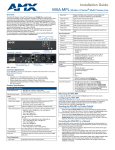
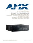
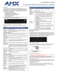
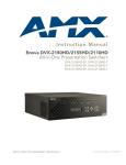
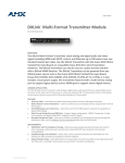
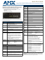
Quick Start Guide
Enova DVX-2150HD/2155HD 6x3 All-In-One Presentation Switcher
Overview
Enova DVX-2150HD/2155HD Specifications (Cont.)
The DVX-2150HD-SP (FG1905-11), DVX-2150HD-T (FG1905-13), DVX-2155HD-SP
(FG1905-12), and DVX-2155HD-T (FG1905-14) are six input, three output, multi-format
matrix switchers with built-in video scalers, microphone mixer, amplifier, and device
controller. These presentation-style switchers incorporate the following:
• A NetLinx controller (equivalent of a NetLinx 3101-SIG central controller)
• Integrated Multi-format and UTP audio / video switcher
• Video scaler
• Audio processor with mic mixing
• Volume controller and audio amplifier
S/PDIF
OUTPUT:
MULTI-FORMAT 2 DVI-I input connectors
VIDEO INPUTS:
HDMI INPUTS:
• 4 HDMI inputs (3-6) (DVX-2150HD devices only)
• 2 HDMI inputs (3-4) (DVX-2155HD devices only)
DXLINK
INPUTS:
2 RJ-45 inputs (5-6) for video, audio, Ethernet, and bi-directional
control of DXLink devices (DVX-2155HD devices only)
VIDEO
OUTPUTS:
• 2 HDMI Output connectors (1-2)
• 1 DXLink output (3)
CONFIG DIP
Switch:
8-position Master configuration DIP switch
PROGRAM
Port:
DB9 connector (male) for serial communication.
ID Pushbutton:
Black ID pushbutton sets the NetLinx Device ID assignments of the
Internal Control Device.
LAN 10/100
Port:
RJ-45 connector provides TCP/IP communication.
AxLink Port:
1 3.5 mm 4-pin captive-wire connector provides data and power to
external control devices.
Power
Connector:
IEC Power cord connector: 100-240V AC, 50-60Hz, 3.3A
FIG. 1 Enova DVX-2150HD-SP 6x3 All-In-One Presentation Switcher (front panel)
The following table lists the specifications for the Enova DVX-2150HD/2155HD 6x3
All-In-One Presentation Switcher:
Enova DVX-2150HD/2155HD Specifications
Power:
100-240V, 47/63 Hz AC supply
Power
Consumption:
• 80 Watts typical without amplifier
• 85 to 90 Watts typical average with amplifier
• 30 Watts typical in low-power mode
Memory:
• 256 MB SDRAM
• 4 GB Flash
Amplifier:
1 Coaxial RCA connector for digital S/PDIF audio output
Twisted Pair Cable
Type:
Shielded Cat6, Cat6A, Cat7*
Twisted Pair Cable
Length:
Up to 328 ft. (100 m)*
Important: DXLink twisted pair cable runs for DXLink equipment shall
only be run within a common building.**
• 2 x 25W into 8 Ohms Class D stereo amplifier (capable of driving
loads in the range of 2-8 ohms) (-SP models only)
• 70V or 100V at 75W amplified variable mono audio (-T models only)
Operating
Environment:
Storage temperature: -10º C to 70º C (14º F to 158º F)
Operating Temperature: 0º C to 40º C (32º F to 104º F)
Operating Relative Humidity: 5% to 85% non-condensing
Enclosure:
Metal with black matte finish
Weight:
18.2 lb (8.26 kg)
Integrated
Controller:
Equivalent of a NetLinx 3101-SIG central controller on-board.
Dimensions
(HWD):
5 3/16" x 17" x 14" (13.2 cm x 43.2 cm x 35.6 cm)
Certifications:
•
•
•
•
Included
Accessories:
•
•
•
•
•
•
•
•
•
1 Power Cord, Universal (64-0009)
2 Connector, Phoenix2, M, TH, R/A, BLACK, 5.08mm (41-0158-SA)
4 Connector, Phoenix5, F, BLACK (41-0336)
2 Connector, Phoenix3, F, BLACK (41-0338)
1 Connector, Phoenix4, F, TH, BLACK, 3.5mm (41-5047)
2 Connector, Phoenix, 8-pin, FEM, BLACK (41-5083)
1 Connector, Phoenix, 6-pin, FEM, BLACK (41-5063)
2 Front Rack Mounting Brackets (62-1905-16 and 62-1905-17)
2 CC-NIRC, IR Emitter with 3.5mm Phoenix Connector
(FG10-000-11)
• 1 CC-DVIM-VGAF, DVI to HD-15 Female Adapter (FG10-2170-13)
• 1 Commoning Strip, Cypher, 8 Pos., 3.5 mm, Phoenix Connector
(41-2105-01)
Optional
Accessories:
•
•
•
•
•
• 1 MB Non-volatile (NVRAM)
Front Panel Components:
LEDs:
• LINK/ACT (green) - blinks when receiving Ethernet data packets.
• STATUS (green) - blinks when the system is communicating
properly.
• INPUT (yellow) - blinks when the Controller is receiving data.
• OUTPUT (red) - blinks when the Controller is transmitting data.
• RS-232/422/485 (red/yellow) - indicate ports are transmitting or
receiving data.
• RELAYS (red) - indicate whether relay channels are active (closed).
• IR/SERIAL (red) - indicate whether IR/Serial channels are
transmitting control data.
• I/O (yellow) - indicate whether I/O channels are active.
LCD display:
Displays volume level and Video, Audio, and Status menu options.
Front panel
pushbuttons:
•
•
•
•
•
Switch
Video Menu
Status
Video Mute
Navigational buttons
•
•
•
•
Take
Audio Menu
Exit
Audio Mute
Rear Panel Components:
RS-232/422/485
3 DB9 (male) connectors for serial control
RELAYS:
1 8-pin 3.5 mm captive-wire connector for Relay control
IR/SERIAL:
8 2-pin 3.5 mm captive-wire connectors for IR/Serial control
•
I/O:
1 4-channel binary I/O port for contact closure and voltage sensing.
•
AUDIO INPUTS: 4 analog audio inputs:
• 2 female 1/8" stereo mini-phono jacks for unbalanced audio
• 2 3.5mm 5-pin captive-wire connector for line level audio
MIC INPUTS:
2 3.5mm 3-pin captive-wire connectors for up to 2 mono microphones
AMP OUT:
• 1 5mm 4-pin captive wire connector (-SP models only).
• Two 2-position captive wire connectors for 70V or 100V mono
amplified audio output (-T models only).
AUDIO
OUTPUTS:
2 3.5mm 5-pin captive-wire connectors for line level audio
•
•
FCC Part 15 Class A
IC CISPR 22 Class A
LVD EN 60950-1
cULus UL 60950-1
• C-Tick CISPR 22 Class A
• IEC 60950-1
• CE EN 55022 Class A and EN 55024
CC-DVI-5BNCM DVI to 5 BNC adapter cable (FG10-2170-08)
CC-DVI-RCA3M DVI to 3 Male RCA adapter cable (FG10-2170-09)
CC-DVI-SVID DVI to S-Video adapter cable (FG10-2170-10)
CC-DVIM-VGAF DVI to HD15 female adapter (FG10-2170-13)
CC-3.5ST5-RCA2F 5-Pin Phoenix Cable to 2 RCA Female
(FG10-003-20)
AVB-RX-DXLINK-HDMI DXLink™ HDMI Receiver Module
(FG1010-500)
AVB-TX-HDMI-DXLINK DXLink HDMI Transmitter Module
(FG1010-300)
AVB-TX-MULTI-DXLINK DXLink Multi-Format Transmitters
(FG1010-310)
AVB-WP-TX-MULTI-DXLINK DXLink Multi-Format Wallplate
Transmitters (FG1010-320-BL/WH)
* For more details and helpful cabling information, reference the white paper titled
"Cabling for Success with DXLink" available at www.amx.com or contact your AMX
representative.
** "Common building" is defined as: Where the walls of the structure(s) are physically
connected and the structure(s) share a single ground reference.
Mounting the DVX into an Equipment Rack
The DVX occupies three rack units in a standard equipment rack. Install the included
rack mounting brackets using the supplied mounting screws prior to securing the unit in
the rack.
Warning: The DVX should not be installed in enclosed spaces. ALWAYS ensure that
the rack enclosure is adequately ventilated. Do not block any ventilation openings. It is
recommended that you leave 1 RU of space above the DVX when you install it in a
rack. DO NOT stand other units directly on top of the DVX when it is rack mounted, as
this will place excessive strain on the mounting brackets.
ALWAYS ensure that the rack enclosure is adequately ventilated. Do not block any
ventilation openings. Sufficient airflow must be achieved (by convection or forced-air
cooling) to satisfy the ventilation requirements of all the items of equipment installed
within the rack.
Note: Connect the LAN port to a LAN with DHCP before powering up the device.
Use the Navigational buttons to traverse the available options and change their values.
FIG. 2 displays the navigational function of each button.
Move up to previous menu configuration parameter
Decrease value, or
change the state of
the selected parameter
Move down to next menu configuration parameter
VIDEO INPUTS
FIG. 2 Navigation buttons
The DVX features 6 connectors which route video from connected source input devices
to the connected output devices.
Selecting a Video Test Pattern
MULTI-FORMAT VIDEO INPUTS (1-2)
Each MULTI-FORMAT VIDEO INPUT connector supports DVI-D, as well as VGA,
S-Video, Composite, Component, and HDMI inputs, using the appropriate adapter
cables. These ports are HDCP compatible.
Consult the Enova DVX-2150HD/2155HD 6x3 All-In-One Presentation Switcher
Operation/Reference Guide for information on adapter cables.
HDMI INPUTS (3-6 on 2150HD, 3-4 on 2155HD)
The HDMI INPUT connectors support digital audio in addition to DVI or HDMI digital
video. All HDMI inputs are HDMI (with 3D and Deep Color) and HDCP compatible.
DXLINK INPUTS (5-6 on 2155HD)
On DVX-2155HD models, ports 5-6 are DXLINK INPUT connectors which transport
digital video, embedded audio, Ethernet, and bi-directional control over twisted pair
cable from DXLink compatible transmitters. Both inputs support HDCP and can supply
power to DXLink transmitters.
Note: Use the DXLINK_IN_ETH command to enable Ethernet traffic through the
DXLink inputs. See the Enova DVX-2150HD/2155HD 6x3 All-In-One Presentation
Switcher Operation/Reference Guide for more information on these commands.
AUDIO INPUTS
The DVX allows independent switching of video and audio. Video and audio inputs of
the same number do not have to be connected to the same source equipment. (The
DVX features 8 audio connectors including the 4 HDMI inputs on the DVX-2150HD, and
the 2 HDMI and 2 DXLink inputs on the DVX-2155HD.)
AUDIO INPUTS (1-2)
The two AUDIO INPUTS connectors receive up to two unbalanced stereo audio inputs.
AUDIO INPUTS (7-8)
The two AUDIO INPUTS connectors can be wired for either balanced (differential) or
unbalanced (single-ended) stereo audio.
AUDIO OUTPUTS (1-3)
The AMP OUT amplified audio output (1) differs according to the DVX model you are
using:
• -SP models use a 4-position captive wire connector to provide amplified, variable,
mono or stereo audio output.
• -T models use a two 2-position captive wire connector to provide 70V or 100V
mono amplified audio output. Connect a speaker to either the 70V or 100V
terminal, but not both simultaneously.
The two AUDIO OUTPUT connectors (2-3) provide line level balanced or unbalanced,
mono or stereo line-level audio output.
VIDEO OUTPUTS (1-3)
2 HDMI Output connectors (1-2) provide HDMI video output.
1 DXLink Twisted Pair output (3) provides digital video, audio, Ethernet, and
bi-directional control over Twisted Pair Cable to DXLink Receivers. The DXLINK output
can provide power to a DXLINK receiver. All video outputs are HDCP compatible.
Note: Use the DXLINK_ETH command to enable Ethernet traffic through DXLINK
outputs. See the Enova DVX-2150HD/2155HD 6x3 All-In-One Presentation Switcher
Operation/Reference Guide for more information on these commands.
Increase value, or
change the state of
the selected parameter
Selecting a test pattern for your input source can help determine if you have your video
devices connected correctly. Perform these steps to select a test pattern:
1.
Press the VIDEO MENU button on the front panel of the DVX to open the Video
Output menu.
2.
Press the left and right navigation buttons to select the output on which to display
the test pattern (ALL, 1, or 2). (Note: You cannot display a test pattern on the
DXLINK output (3) from the front panel menu. Refer to documentation for the
DXLink receiver for information on displaying a test pattern from the receiver.)
3.
Press the down navigational button until the Output Test Pattern option appears.
4.
Use the left and right navigational buttons to select an appropriate output test
pattern.
Selecting an Audio Test Tone
Selecting a test tone for your input source can help determine if you have your audio
devices connected correctly. Perform these steps to select a test tone:
1.
Press the AUDIO MENU button on the front panel of the DVX to open the Audio
Output menu.
2.
Press the left and right navigation buttons to select the output on which to play the
test tone (ALL, 1, 2, or 3).
3.
Press the down navigational button until the Test Tone option appears.
4.
Use the left and right navigational buttons to select an appropriate audio test tone.
Setting the Video Type for a Video Input
Each video input type must be set manually. Perform these steps to set the video type
for a video input:
1.
Press the VIDEO MENU button on the front panel of the DVX two times to open
the Video Input menu.
2.
Press the left and right navigation buttons to select the input to change. You can
select any input from 1-6.
3.
Press the down navigational button until the Type option appears.
4.
Use the left and right navigational buttons to select the video format for the
selected input. For Multi-Format inputs, you can choose from HDMI, DVI, VGA,
Component, S-Video, and Composite. The default setting is Component. For
HDMI inputs, you can choose from HDMI or DVI.
Locating the IP Address of the DVX
You can locate the IP address of the DVX by using the buttons on the front panel of the
unit. The IP address appears on the LCD display on the front panel of the switcher.
Perform these steps to locate the IP address of the unit:
1.
Press the STATUS button on the front panel of the unit to open the Status Menu.
The Status options appear on the LCD display.
2.
Use the UP and DOWN navigational arrow buttons to navigate through the
options until you find the switcher’s IP address. Note the IP address for future
reference.
Note: You can use the Status menu to verify current TCP/IP settings using the UP and
DOWN navigational buttons.
Using a Web Browser
You can access the configuration settings for the DVX by using the buttons on the front
panel of the unit or by using a web browser.
The system configuration pages are available by entering the IP address of the NetLinx
master into the location bar of your web browser. Entering your IP address into your
web browser opens the Main WebControl page. Perform these steps to access the
configuration settings:
1.
Open a web browser, and enter the IP address of the DVX in the location bar of
the web browser. The Main WebControl page opens.
Note: WebControl requires that you install the latest version of the Adobe Flash Player
plug-in for your browser. If your browser does not have the Flash Player plug-in
installed, you will be prompted to install it.
2.
Use the Device options menu at the top of the screen to select <DEVICE #> DVX-215xHD Switch Device.
Using the Front Panel Buttons
Additional Documentation
You can access the configuration settings for the DVX by using the VIDEO MENU,
AUDIO MENU, SWITCH, and STATUS buttons on the front panel of the DVX. Pressing
any button opens its respective menu on the LCD display on the front panel.
Press the TAKE pushbutton to implement an audio/video switch while you are in the
Switch menu on the LCD display. When in an audio or video menu, press the button to
cycle through audio and video inputs or outputs (depending on the menu.)
For more information, consult the Enova DVX-2150HD/2155HD 6x3 All-In-One
Presentation Switcher Operation/Reference Guide available at www.amx.com.
PROGRAM Port
The PROGRAM port connects the DVX to a communication port on a PC, and is
intended primarily to be used to configure system settings.
Accessing the Configuration Settings
For full warranty information, refer to the AMX Instruction Manual(s) associated with your Product(s).
8/13
©2013 AMX. All rights reserved. AMX and the AMX logo are registered trademarks of AMX.
AMX reserves the right to alter specifications without notice at any time.
3000 RESEARCH DRIVE, RICHARDSON, TX 75082 • 800.222.0193 • fax 469.624.7153 • technical support 800.932.6993 • www.amx.com
93-1905-11
REV: G