1
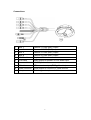
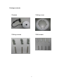
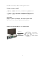
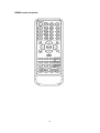
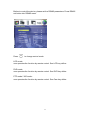
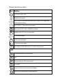
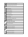
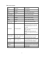
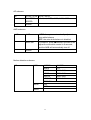
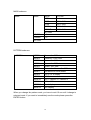
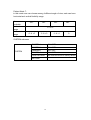
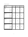
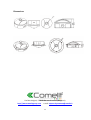
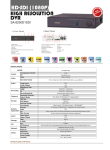
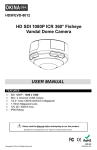
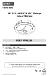
FISH-EYE HD-SDI CAMERA, 5 MEGAPIXEL
ART. HDCAM360A
Please read this manual thoroughly before use, and keep for future reference
Via Don Arrigoni, 5 24020 Rovetta S.Lorenzo (Bergamo)
http://www.comelitgroup.com e-mail: [email protected]
1
SAFETY PRECAUTIONS
Please read before using
The lightning flash with arrowhead symbol, within an
equilateral triangle, is intended to alert the user to the
presence of insulated dangerous Voltage within the
product’s enclosure that may be sufficient magnitude to
constitute risk of electrical shock to persons.
The exclamation point within an equilateral triangle is
intended to alert the user to the presence of important
operation and maintenance (servicing) instructions in the
literature accompanying the appliance.
1. Please read the service manual in details before using.
2. Don't try to disassemble the chassis or the part easily, in case that touch the power by
mistake, is shocked by electricity the danger or caused inside parts to be damaged,
3. Do not attempt to service this unit yourself unless you are authorized to do so. Opening
cover may exposure you to dangerous voltage or other hazards. Refer all servicing to
qualified personnel only.
4. When being regular, please lock the parts firmly first to prevent the machine damage.
5. Please connect correctly in accordance with the regulation, prevent the machine from using,
or striking improperly.
6. Please don't use any organic solution or the corrosively sanitizer to insert and wipe away
the chassis outside. While inserting and wiping away, please turn off the power, and use the
clean cloth is stained with letting a small amount of branch water, insert and wipe away
appearance.
7. Please don't use the camera under the following abominable environments: temperature is
lower than –10°C or is higher than +50°C.
2
Product Feature
1.
2.
HD CCTV 5 Mega Pixel.
SDI output.
3.
4.
5.
6.
HDMI output.
CVBSx4 output.
360° and 180° panorama view.
Virtual PTZ function.
7.
8.
9.
10.
Auto Pan Function.
Multiple screen display.
Privacy mask.
Motion tracking.
11. Built-in microphone.
3
Specifications
Model
360° panoramic camera
Signal System
NTSC or PAL
Pick up device
1/3.2” Color CMOS QSXGA (5Mega Pixel : 2592x1944) image sensor
Synchronizing
Internal
Scanning System
2:1 Interlace
S/N Ratio
More than 51dB
Electronic Shutter
x3; x2; x1; AUTO; 1/100; 1/120; 1/250
White Balance
Auto
Diagonal
185°
Angle of
view
Horizontal 185°
Vertical
185°
Gamma Correct
0.45 / 1
RS485
PELCO D / 9600
Video Output
4 channels CVBS / HDMI / SDI
Lens Type
Board lens 1.19 mm / F2.0
Format
1080p
Power Source
12 VDC jack ± 10% / 1A
Power Consumption 6.6 W (max)
Current
Operating
Temperature
550 mA (max)
-10°C ~ 50 °C (14°F ~ 122°F )
Storage Temperature -20°C ~ 70°C (-4°F ~ 158°F)
Dimensions (H x ø)
78.82 x 145 mm
78.82 x 190 mm
4
Connections:
①
①
①
①
①
①
①
①
①
1
label 1
Camera 1 CVBS (BNC) output
2
label 2
Camera 2 CVBS (BNC) output
3
label 3
Camera 3 CVBS (BNC) output
4
label 4
Camera 4 CVBS (BNC) output
5
RS485 cable
Purple + / White -
6
RCA cable
Audio output to speaker or DVR audio input
7
Power cable
12 VDC jack
8
SDI cable
SDI connector output (BNC gold color)
9
HDMI connector
HDMI output to connect to a HDMI monitor
10
Microphone
Pinhole type microphone built in
5
Package contents
Camera
Ceiling cover
Ceiling screws
Wall screws
6
This 360° camera can be installed into different co nfiguration thanks to its rich
connection. You will have an overview of different scenario in the next pages.
A) Scenario without DVR
1. The camera uses the SDI connector output or the HDMI connector to
a HD-SDI monitor that has RS485 built in connector.
The user points the remote controller to the monitor and controls the
camera
2.
The camera uses the SDI connector output or the HDMI connector to
a HD-SDI monitor that doesn’t have RS485 built in connector.
The user link the 2 RS485 wires from the camera to a keyboard
controller
B) Scenario with DVR
1. The DVR only supports SDI signal input
The camera used the SDI connector output to the DVR SDI input
The user link the 2 RS485 wires to the RS485 terminal of the DVR
The DVR uses the HDMI connector output to a HDMI monitor
The user controls the camera with the mouse or the remote controller
of the dvr
2.
The DVR doesn’t have SDI signal input and only accepts analog
signal
The camera uses the 4 BNC connector output to the 4 video input of
the DVR.
The user can’t access to the 180° and 360° view
3.
The DVR can accept both SDI and analog signal
The camera uses the SDI connector output to the DVR SDI input
The camera uses the 4 BNC connector output to the 4 video input of
the DVR
The user links the 2 RS485 wires to the RS485 terminal of the DVR or
to the RS485 terminal of the keyboard controller
7
RS485 connection with keyboard
The 360° camera is set in protocol PELCO-D and baud rate 9600.
User can use keyboard, DVR or any RS485 device to control 360° camera.
Ex.: Keyboard
RS 485 port
RS 485 cable
RS 485 port 1
Purple + positive
RJ 11 pin 3 +, pin --
White - negative
How to setup connection between keyboard and camera
Press MENU button of keyboard for function setup
CAM : 001< MUX : 00
DV : 00
1. Keyboard ID Setup
Setup Menu
2. Master Setup
>. System Menu
3. CAM Type setup.
CAM Menu
4. Baud Rate Setup
Using direction key to select system menu and then press ENTER to get in.
Follow below setting and ready to control camera with command.
1. Keyboard ID Setup:
press ENT press 1 press ENT ESC
2. Master Setup:
press ENT press 1 press ENT ESC
3. CAM Type Setup:
press ENT choose protocol 5: PELCO-D press ENT ESC
4. Baud Rate Setup:
press ENT choose Baud Rate 1: 9600 press ENT ESC
5. Press “ESC” to exit menu.
Note: if you are using others keyboard brand, please make sure the protocol
setting is on PELCO-D and baud rate 9600 and the control command is same
as usual.
Command:
the default screen mode is 5. It displays in 5 windows (quad + 360° view)
Camera 1 ~ 4 is a virtual split from 360° screen. U ser can control camera 1~4
8
like PTZ dome to do Up / Down / Left / Right movement.
Controls on screen in mode 5:
1.
2.
3.
4.
Press 1 + CAM to call camera 1 and after use joystick to move.
Press 2 + CAM to call camera 2 and after use joystick to move.
Press 3 + CAM to call camera 3 and after use joystick to move.
Press 4 + CAM to call camera 4 and after use joystick to move.
Get in menu:
press 95 + PRESET to call menu. Use joystick to select items.
Up / Down for item chooses, Right to enter in sub items.
RS485 connection with Monitor with RS485 built in
RS 485 port
RS485 A+
RS 485 cable
Purple + positive
RS485 B-
White - negative
9
RS485 remote controller
10
Before to control the device, please set the RS485 parameters. Press RS485
set button into RS485 menu.
Press
to change control mode
LCD mode:
user operates the function by remote control. See LCD key define
DVR mode:
user operates the function by remote control. See DVR key define
PTZ mode / 360° mode:
user operates the function by remote control. See Cam key define
11
Remote controller key define
Key Define
LCD power ON / OFF
RS485 menu setup
LCD / DVR / CAM OSD item select Up / Down / Left / Right key
DVR playback status
LCD / DVR / CAM control mode switch
Call desire LCD / DVR / CAM Device Menu
Displays the LCD source information
LCD volume setup
LCD audio soundless
VGA mode auto adjust
Quit desired DVR OSD setup or number wrong typing
LCD
Direct select the AV1 source input
N/A
Direct select the VGA source input
For HDMI
Jump to Picture in Picture screen display
Picture in Picture screen source selection
12
Picture in picture screen source exchange
Picture ratio selection: Under / Full / Over
DVR
Channel sequence
Quad screen selection
9 split screen selection
16 channel selection
Jump to playback mode
Manual recording
Jump to time search of playback mode
Jump to backup mode
CAM (P/T/Z dome; 360° mode)
PTZ dome ID selection / Set, Call, Clear Preset
DVR full channel selection
FOCUS
PTZ dome’s lens in manual focus
PTZ dome’s lens in manual focus
IRIS
PTZ dome’s lens in manual Iris
PTZ dome’s lens in manual Iris
13
ZOOM
Control PTZ dome’s lens zoom in and out
PRESET
Set a Preset point
Call a Preset point
Clear a Preset point
14
RS485 connection with DVR
RS 485 port
RS485 +
RS 485 cable
Purple + positive
RS485 -
White - negative
Protocol configuration:
please go to your DVR RS485 (PTZ) setting. Select the camera and 360°
It depends on which channel SDI is connected. If camera is on channel 1,
please make sure the address is from 1 to 4, choose protocol PELCO-D and
baud rate 9600.
Please go to your DVR PTZ control mode to start operate 360° camera.
Note: when you are inside the camera OSD, if there is suddenly power
shortage, the setting will not be saved in the memory. You must exit the osd or
wait the OSD disappears to validate the modified setting in the memory!
15
Main menu structure
Item
Selection
Description
AE
Submenu
Auto exposure
AWB
Submenu
Auto white balance setting
BRIGHTNESS
1~9
Picture brightness adjust
SATURATION
1~9
Picture saturation adjust
MD
Submenu
Motion detection setting
MASK
Submenu
Picture mask zone setting
00~09
Picture noise reduction setting
NOISE
REDUCTION
AUTO: means that camera will
adjust automatically the mode after
a period of time (0, 3, 5, 10, or 15
seconds)
DAY/NIGHT
AUTO/DAY/NIGHT
DAY: means that camera will always
be on day mode
NIGHT: means that camera will
always be on night mode (black and
white)
SHOW MODE
WALL 0 / WALL 90 /
Select the desired mode and then
WALL 180 / WALL 270 /
press enter button or 94 + Preset
DESK / CEILING
(keep press after hear 2 beeps)
Select the desired pattern and then
PATTERN
Mode 1~Mode 13
press ENTER button or 94 + Preset
(keep press after hear 2 beeps)
SYSTEM
Submenu
System status setup
Will reset the device, just press right
REBOOT
arrow to reset
EXIT
Exit the menu
16
AE submenu
AE
50 Hz / 60 Hz 50 Hz / 60 Hz
SHUTTER
SPEED
x3; x2; x1; AUTO; 1/100; 1/120; 1/250
Return
AWB submenu
AWB
AWB
AUTO: the system automatically adjusts the
auto white balance
OFF: the auto white balance is disabled
AWC SET
To enable it, press direction one time it will
adjust the auto-white control in 9 seconds,
and the AWB will automatically turn off
Return
Motion detection submenu
MD
AREA
ACTION
ON/OFF
AREA
1~4
XPOS
0000~1943
YPOS
0000~1943
WIDTH
0256~1943
HEIGHT
0256~1943
RETURN
MODE
ON
OFF
Return
17
MASK submenu
MASK
MASK
MODE
OFF/ON
AREA
1~4
XPOS
0001~1943
YPOS
0001~1943
WIDTH
0000~1943
HEIGHT
0000~1943
RETURN
COLOR
1~5
TRANSP
1~3
RETURN
PATTERN submenu
PATTERN
MODE1
Camera 1 + 360° view
MODE2
Camera 2 + 360° view
MODE3
Camera 3 + 360° view
MODE4
Camera 4 + 360° view
MODE5
Quad + 360° view
MODE6
Camera 1 + Camera 3 + 360° view
MODE7
See below for more details
MODE8
180° in 16 :9 display
MODE9
360° flat
MODE10
180° + Camera 3 + Camera 4
MODE11
180° + 180°
MODE12
Quad display
MODE13
360° display
When you change the pattern mode, you have to wait 10 sec until it change to
selected mode. If you want to immediately see the mode please press the
ENTER button.
18
Pattern Mode 7:
in this mode user can choose among 4 different angle of view, each can have
horizontal and vertical flexibility range
View
available
120°
140°
Verticale
180°
-5 +5
range
Horizontal
range
160°
-5 +5
-3 +3
-1 +1
0
SYSTEM submenu
SYSTEM
CAMERA1
ON / OFF
CAMERA2
ON / OFF
CAMERA3
ON / OFF
CAMERA4
ON / OFF
LOAD DEFAULT
Will reset the device to factory default
RETURN
19
Command list
For camera 1 to 4 it is possible to define 3 Preset points that will be use for the
Preset Cruise (76 + Preset) and the Preset Sequence display (66 + Preset)
To define Preset 1 on camera 1:
Call camera 1
Select your preset view by adjusting with the joystick
Press 1 then press PRESET button 3 sec until you hear a bip (OSD will display
on screen POINT1)
(Setting may differ from the type of RS485 device you are using)
Same for the other preset
Call Preset 95: displays the menu of the 360° camer a
Call Preset 94: will apply immediately the selected mode
Call preset 93: after you selected your desired mode and that you position the
view of the camera, you can save the current view by calling Preset 93. OSD
will display on screen SAVE
Call Preset 76: run the auto pan function. OSD will display on screen TOUR
This function is also available on the keyboard by pressing directly AUTO PAN
hot key. In this mode the motion detection will be disabled
Call Preset 66: displays each preset without transition. Ideal for preset whose
distance is very long. In this mode the motion detection will be disabled. OSD
will display on screen SCAN
Motion detection and tracking
This camera has a motion detection feature and tracks a moving object in the
field of view. For configuration without dvr it can be a good alternative for live
monitoring
Due to the high level of processing for the CPU, it can be activated on one
channel only.
It doesn’t apply for 180° and 360° view.
20
Pattern description:
PATTERN
Preset
cruise
Preset
sequence
Motion
tracking
yes
yes
yes
yes
yes
yes
yes
yes
yes
yes
yes
yes
MODE 1
MODE 2
MODE 3
MODE 4
21
PATTERN
Preset
cruise
Preset
sequence
Motion
tracking
yes
yes
yes
yes
yes
yes
no
no
no
no
no
no
MODE 5
MODE 6
MODE 7
MODE 8
22
PATTERN
Preset
cruise
Preset
sequence
Motion
tracking
no
no
no
yes
yes
yes
no
no
no
yes
yes
yes
no
no
no
MODE 9
MODE 10
MODE 11
MODE 12
MODE 13
23
Dimensions
Via Don Arrigoni, 5 24020 Rovetta S.Lorenzo (Bergamo)
http://www.comelitgroup.com e-mail: [email protected]
24