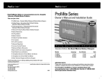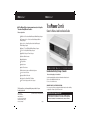
1
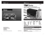
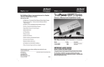
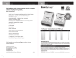
ProMa r i ne r
ProMa r i ne r
™
Visit ProMariner Online at www.promariner.com, for a Complete
Selection of Quality Marine Products...
Here are just a few:
™
TruePower Combi
Owner's Manual and Installation Guide
ProMite Series - Recreational Grade Waterproof Marine Battery Chargers
ProTournament Series - Professional Grade Waterproof Marine
Battery Chargers
ProSport Series - Heavy Duty Recreational Grade Waterproof
Marine Battery Chargers
ProNautic C3 Series All Digital Dry Mount Battery Chargers
ProTech-i Series Dry Mount Battery Chargers
Digital Mobile Charge In-Transit Chargers
TruePower Marine Inverters
Battery Maintainers
AC Plug Holders
Battery Isolators
Isolation Transformers
1 0 0 0 - 2 5 0 0
FailSafe Galvanic Isolators and Monitored Systems
|
1 2 / 2 4
V o l t s
Combination Battery Charger / Inverter
Corrosion Control Products
Please read thoroughly prior to installation
Waterproof Marine Binoculars
Contains Important Installation and Operation Information and instructions for:
QS Series - Quasi (Modified) Sine Wave Series
PS Series - Pure Sine Wave Series
A Complete Line of Hand Held Test Meters
Online Technical Support and Service Support
IMPORTANT NOTICE - SAVE THESE INSTRUCTIONS
Please save and read all safety, operating and installation instructions before installing
or applying DC or AC power to your TruePower Combi.
Visit frequently, we are always adding new products for your
boating enjoyment!
Factory Service
TEL: 1-800-824-0524
www.promariner.com
8:30 - 5:00 Eastern Standard Time
200 International Drive, STE 195
Portsmouth, NH 03801
W a t t s
specifications subject to change without notice
Your Satisfaction is Important to Us!
Do Not Return this Product to the Retailer or Dealer for any service or warranty requirements.
Please call our Customer Care Department line at 1-800-824-0524 from 8 am to 5 pm (Eastern
Standard Time) for any warranty, service or installation assistance you may need. Thank You
010909
Customer Service & Warranty
Table of Contents
We are committed to customer satisfaction and value your business. If at any
time during the warranty period you experience a problem with your new TruePower
Combi simply call us at 1-800-824-0524 during standard business hours
(8:30 AM – 5 PM Eastern Standard Time) for technical support.
Warnings...
Personal Precautions...
Overview...
Features...
Setup And Operation...
Installation...
Post Installation - Pre-start Checklist...
Troubleshooting...
Appendix 1 Load Calculations...
Appendix 2 Technical Specifications...
TruePower Combi
Two Year Limited Factory Warranty
Each TruePower Combi model is guaranteed against defects in material and workmanship to the original
consumer in normal use for 2 years from the date of purchase. Professional Mariner, LLC will at it's discretion
repair or replace free of charge any defects in material or workmanship. The following conditions apply:
• Warranty is calculated from manufacture date if not registered within
30 days of purchase.
• Warranty void if unauthorized repairs attempted.
• Customer is responsible for returning the product to Professional Mariner, LLC.
Inbound shipping costs must be paid by customer.
• This warranty does not cover blemishes due to normal wear and tear or
damaged caused by accidents, abuse, alterations or misuse.
• Cosmetic repairs can be done at owner's request and expense.
Purchase or other acceptance of the product shall be on the condition and agreement that Professional Mariner
SHALL NOT BE LIABLE FOR INCIDENTAL OR CONSEQUENTIAL DAMAGES OF ANY KIND. (Some states do not
allow the exclusion or limitation of incidental or consequential damages, so the above limitations may not apply
to you.) Professional Mariner neither assumes nor authorizes any person for any obligation or liability in
connection with the sale of this product.
To make a claim under warranty, call 1-800-824-0524 or visit www.promariner.com identifying the product and
giving its locations. Follow the company's return instructions, which will then be provided by the company.
Professional Mariner will make its best effort to repair or replace the product, if found defective within the
terms of the warranty, within (30) days after return of the product to the company. Professional Mariner will
ship the repaired or replaced product back to the purchaser.
This warranty gives you specific legal rights, and you may also have other rights, which vary from state to state.
This warranty is in lieu of all others expressed or implied.
Factory Service Center & Technical Offices
Professional Mariner, LLC
200 International Drive STE 195
Portsmouth, NH 03801
Tel: 1-800-824-0524 www.promariner.com
Professional Mariner, LLC Headquarters
Tel: (603) 433-4440 / Fax: (603) 433-4442
1-3
4
5
6-8
9-14
14-26
27
28-29
30-32
33-34
Introduction
Thank you from all of us at ProMariner. Congratulations on your recent purchase
of a TruePower Combi Charger/Inverter!
Important Notice – Please read and understand this manual before installing your
TruePower Combi Charger/Inverter.
This manual is written to assist in the installation of your new TruePower Combi
Charger/Inverter; however, since this is a permanent AC and DC hardwired installation,
ProMariner strongly recommends that a Certified Marine Electrical Technician® trained
by the American Boat & Yacht Council (ABYC) perform the installation. The TruePower
Combi unit you have purchased is constructed to the safety standards of the ABYC to
prevent fire and electrocution; the installation must conform to these same industry
standards. For more information on ABYC, their Standards and Technical Information
reports for Small Craft, and to find a certified technician near you, visit www.abycinc.org.
To Preclude a Safety Hazard, all existing AC and DC electrical components (e.g.
wire, fuses, circuit breakers, battery switches, connections) must be inspected for
proper condition prior to installation. Failure to confirm adequate condition and proper
installation to ABYC Standard E-11 AC & DC Electrical Systems on board boats may
result in a dangerous condition and/or premature failure of this or other installed
electrical components. Any and all areas of the existing system that are found not in
compliance with ABYC E-11 must be replaced prior to installation.
Warnings
Warnings
2
1
Warnings
Warnings
Important Notice: FCC Class A Notification & International Standards Compliance
NOTE: This equipment has been tested and found to comply with the limits for a Class A digital device,
pursuant to Part 15 of the FCC Rules. These limits are designed to provide reasonable protection
against harmful interference when the equipment is operated in a commercial environment. This
equipment generates, uses, and can radiate radio frequency energy and, if not installed and used
in accordance with the instruction manual, may cause harmful interference to radio communications.
Operation of this equipment in a residential area is likely to cause harmful interference in which case
the user will be required to correct the interference at their own expense.
If in a residential setting you are encountering interference with TV and Radio reception
while NOT in inverter mode, then: simply disconnect AC power from the TruePower
Combi Charger/Inverter to confirm if this unit is causing the interference, if so explore
the following options to minimize interference:
1) Make sure your AC connections include a proper Ground connection
2) Reposition your receiving antenna
3) Purchase a separate AC line filter
4) Relocate the affected appliance so it is further separated from the
TruePower Combi Charger/Inverter
This equipment has been designed to comply with:
American Boat & Yacht Council A-31 Battery Chargers and Inverters
FCC Class A
Underwriters Laboratories: Standard 1236 Battery Chargers for Charging Engine Starter Batteries
Standard 458 Power Converter/Inverter Systems for Land Vehicles and Marine Crafts
230VAC Models
DANGER
HIGH VOLTAGE
AVOID SERIOUS INJURY OR DEATH FROM ELECTRICAL SHOCK.
BEFORE PERFORMING ANY ELECTRICAL WORK TURN OFF AC POWER SUPPLY
DANGER
EXPLOSION HAZARD
AVOID SERIOUS INJURY OR DEATH
MAKE CONNECTIONS IN AN ATMOSPHERE FREE OF EXPLOSIVE FUMES
WARNING
LOW VOLTAGE
AVOID SERIOUS INJURY FROM ELECTRICAL BURNS AND SPARKS.
BEFORE PERFORMING ANY ELECTRICAL WORK DISCONNECT ANY DC POWER
SUPPLY FROM UNIT
CAUTION
HOT SURFACES – TO REDUCE RISK OF BURNS DO NOT TOUCH WHILE IN SERVICE
CHARGE ONLY USER SELECTED TYPE BATTERIES
(Flooded, AGM, Gel, or Calcium)
OTHER TYPES OF BATTERIES MAY BURST CAUSING PERSONAL
INJURY AND DAMAGE
RISK OF ELECTRIC SHOCK, NO USER SERVICEABLE PARTS, RETURN TO
MANUFACTURER FOR SERVICING
THIS UNIT IS NOT IGNITION PROTECTED
THESE INSTRUCTIONS – This manual contains important safety, operating
! SAVE
and installation instructions for these TruePower Combi models:
TruePower Combi - Combination Charger/Inverter
(110 VAC 60 Hz) 12 Volt QS Models
01012 True Power Combi Charger/Inverter - 110vac 60hz - 12Vdc - 40A
1000W Continuous/3000W Peak Surge
01512 True Power Combi Charger/Inverter - 110vac 60hz - 12Vdc - 40A
1500W Continuous/4500W Peak Surge
02412 True Power Combi Charger/Inverter - 110vac 60hz - 12Vdc - 50A
2500W Continuous/7200W Peak Surge
(110 VAC 60 Hz) 24Volt QS Models
01524 True Power Combi Charger/Inverter - 110vac 60hz - 24Vdc - 20A
1500W Continuous/4500W Peak Surge
02424 True Power Combi Charger/Inverter - 110vac 60hz - 24Vdc - 25A
2500W Continuous/7200W Peak Surge
(230 VAC 50 Hz) 12 Volt QS Models
01513 True Power Combi Charger/Inverter - 230vac 50hz - 12Vdc - 40A
1500W Continuous/4500W Peak Surge
02413 True Power Combi Charger/Inverter - 230vac 50hz - 12Vdc - 50A
2500W Continuous/7200W Peak Surge
(230 VAC 50 Hz) 24Volt QS Models
01525 True Power Combi Charger/Inverter - 230vac 50hz - 24Vdc - 20A
1500W Continuous/4500W Peak Surge
02425 True Power Combi Charger/Inverter - 230vac 50hz - 24Vdc - 25A
2500W Continuous/7200W Peak Surge
Warnings
Personal Safety Precautions
3
4
Warnings
TruePower Combi - Combination Charger/Inverter
(110 VAC 60 Hz) PS Models
02012 True Power Combi Charger/Inverter - 110vac - 60Hz - 12Vdc - 70A
2000W Continuous/6000W Peak Surge
02024 True Power Combi Charger/Inverter - 110vac - 60Hz - 24Vdc - 35A
2000W Continuous/6000W Peak Surge
(230 VAC 50 Hz) PS Models
02013 True Power Combi Charger/Inverter - 20vac - 50Hz - 12Vdc - 70A
2000W Continuous/6000W Peak Surge
02025 True Power Combi Charger/Inverter - 230vac - 50Hz - 24Vdc - 35A
2000W Continuous/6000W Peak Surge
! Do not expose this unit to rain or snow
! Use of attachments not recommended or sold by Professional Mariner, LLC will void
warranty and may result in the risk of fire, electrical shock or personal injury.
! Do not operate the unit if it has been dropped or visibly damaged in any way
! Do not disassemble the unit. If service or repair is required please contact ProMariner
customer service at 1-800-824-0524
! To reduce the risk of electrical shock, remove connection to AC shorepower and DC
connections prior to maintenance or cleaning. Turning off controls WILL NOT reduce
this risk.
WARNING - RISK OF EXPLOSIVE GASSES
WORKING IN THE VICINITY OF A LEAD-ACID BATTERY IS DANGEROUS. BATTERIES
GENERATE EXPLOSIVE HYDROGEN GAS DURING NORMAL BATTERY OPERATION.
FOR THIS REASON IT IS OF UTMOST IMPORTANCE THAT EACH TIME BEFORE USING
YOUR CHARGER YOU READ THIS MANUAL AND FOLLOW THE INSTRUCTIONS EXACTLY.
! To reduce the risk of battery explosion, follow these instructions and those published
by the battery manufacturer and any equipment you intend to use in the vicinity of the
battery(s). Carefully review the cautionary markings on this equipment.
Personal Safety Precautions
! HELP - Someone should be within the range of your voice or close enough to come to
your aid when working with a lead-acid battery.
! CONTACT - Have plenty of soap and water nearby in case battery acid comes in contact
with skin, clothes, or eyes. If battery acid contacts skin or clothing, wash immediately with
soap and water. If acid enters eye, immediately flood eye with running cold water for at
least 10 minutes and seek medical attention immediately.
! WEAR - Complete eye protection and protective clothing. Avoid touching eyes while
working near battery(s).
! NEVER - Smoke or allow a spark or flame within the vicinity of the battery work area.
! SPARK - Be very cautious about dropping metal objects such as screwdrivers and
wrenches onto a battery. This could short-circuit the battery and immediately cause a
spark that may result in a fire or explosion.
! REMOVE - All personal metal items such as rings, watches, bracelets, etc. when working
near a battery. A battery can produce a short circuit current high enough to weld a ring
or any other metal causing serious burns.
! DRY CELL BATTERIES - Never use the battery charger feature to charge dry cell batteries
that are commonly used with home appliances i.e. a cordless power drill battery. These
batteries may burst and cause injury to persons and damage property.
! FROZEN BATTERY - Never charge a frozen battery.
TruePower
Tr u e P o w e r C o m b i F e a t u r e s
5
6
Overview
Overview
Features
UNPACKING AND INSPECTION
Thoroughly inspect your TruePower Combi unit. Take care in moving the unit as it weighs
approximately 42 lbs.
1.Remote Panel Indicator LED’s
2.Auto Standby/Off/On Switch
The package should contain the following:
1) TruePower Combi unit
2) Parts package including:
DO NOT attempt to install or operate the unit if it has been damaged in any way.
AC Connections
DAMAGE - If any parts are missing or damaged, or the unit has been damaged in shipping
contact ProMariner customer service at 1-800-824-0524, do not take back to place of
purchase.
LED Status Indicator Center
DC Connections
a. +(Red) & -(Black) DC terminal covers and 8 (4 per cover) machine screws.
b. AC Terminal Cover and 2 strain relief connectors plus 2 screws
c. Remote package including panel, cable and mounting screws (if so equipped)
d. Owners/Installation manual
Battery Type Selector
Features
SMART TECHNOLOGY - Your new ProMariner TruePower Combi unit is current limiting
with built in “smart” features to monitor vital functions and preclude damage to the
charger and the installed system. The unit incorporates alarms, indicators and an auto
shut-down feature for peace of mind and trouble free operation. This section contains
descriptions of the LED indications and functions of controls. A more detailed description
of LED and audible warning signals can be found in the Troubleshooting section. Turning
the unit OFF and ON again will restart the unit after a fault, however, if the fault is still
present, the unit will again shut down.
INVERTER – The TruePower Combi serves as a Pure Sine wave or a Quasi (modified) Sine
wave inverter, converting DC power to clean, reliable AC power.
NOTE: This unit requires a large amperage draw from a DC battery when in Inverter mode.
Care must be taken during installation to provide properly sized cables from the battery
to the inverter. Cable runs must be as short as possible and of the appropriate size and
type. See the Installation section for more details.
CHARGER – The TruePower Combi also serves as a high efficiency automatic battery charger
suitable for all commonly available battery types (See Section 3 on the Features Table) .
TRANFER SWITCH – The TruePower Combi includes an internal, automatic 30 amp AC
Transfer switch that senses the presence of AC shore/station power. Upon connection
to a shore power/shore station source, the Combi will switch from INVERTER mode
(providing AC power via DC battery source) to CHARGE mode, automatically. This switch,
in compliance with ABYC E-11, disconnects the neutral AC lead from the AC ground when
in shore/station power mode.
1. Remote Panel LED Indicators
LED Color Function When Illuminated
Shore Station/ Power Charger Green
Shore/station power Connected/Charging
Inverter
Green
Inverter On/Shore/station power disconnected
Fault Condition
Red
Fault Condition, See Troubleshooting Section
NOTE: This panel is removable from the TruePower Combi unit to be located in an area of
greater convenience. A dummy plate is included in the package. See the Installation
section for more details on removal of the remote panel and installation of the dummy plate.
2. Three Position Rocker Switch (Inverter feature ONLY)
Switch Position
Action
Auto Standby
Power on with Standby mode. Loads connected
below 20W will NOT activate the Inverter
Power Off
Both the Inverter and the charger disabled.
Power On, Without Auto Standby
Power to Inverter is enabled, Auto Standby disabled.
Resetting the Unit After a Fault
Cycle power Off, then On again, the unit will reset.
The unit will continue to shut down if the fault is
present. In this event, consult the Troubleshooting
section of this manual.
Tr u e P o w e r C o m b i F e a t u r e s
TruePower Combi Features
8
7
Features
Features
3.Battery Type Selector
Switch Setting
0
1
2
3
4
5
6
7
8
9
Description
Factory set-up
Gel 1
AGM 1
AGM 2
Sealed Flooded
Gel 2
Flooded
Calcium
Re-Condition
Custom
4. LED Status Indicator Center
LED Color
Auto Standby
Green
Over load
Red
Over Temp
Red
Ready
Green
Charging
Yellow
Inverter
Green
Shore/StationPower
Green
Boost Charge
Voltage
12V
24V
N/A
N/A
14.0
28.0
14.1
28.2
14.6
29.2
14.4
28.8
14.4
28.8
14.8
29.6
15.1
30.2
15.5
31.0
N/A
N/A
Float Charge
Voltage
12V
24V
N/A
N/A
13.7
27.4
13.4
26.8
13.7
27.4
13.8
27.6
13.8
27.6
13.3
26.6
13.6
27.2
4 Hours, then Off
N/A
N/A
Function When Illuminated
Auto Standby Mode
Over Load Fault Condition
Over Temperature Fault Condition
Batteries are Charging in Float Charging Mode
Batteries are Charging in Boost Charging Mode
Unit is in Inverter Mode
AC Shore/station power is connected
1. Remote Control Connection
Provided for Optional Local Mounting of Status Panel and Operating Switch. (See
Installation for more details)
2. DC Positive and Negative Connections
Corrosion Resistant Mounting Studs, Provided with Multi-Directional Protective Cover. (See
Installation for more details). These conductors provide power to the inverter from the
battery and are also used for the charging feature when shore/station power is present.
NOTE: While your TruePower Combi does not require a fuse at the charger/inverter DC
connections IT DOES require a fuse at the connection to the battery. This is supplied by the
installer and is NOT included in this package. See the Installation section for more details.
3. Auto Cooling Fan
Your TruePower Combi Includes a Cooling Fan that is operational in both Invert and Charge
mode. The fan keeps the TruePower Combi at an acceptable temperature. The fan operation
is dependant upon unit temperature, charge current, and inverter load. There is no user
requirements for proper fan operation, fan cycling is part of the units normal operation.
4. DC Grounding Conductor (Earth)
An Additional corrosion resistant metal stud is provided for a connection to the installed
DC Negative Bus, or Engine Negative Terminal. This is in compliance with ABYC A-31,
the conductor used is allowed to be 1 size smaller than the positive conductor used.
(See Installation for more details). This is an essential safety connection, do not attempt
operation without this conductor properly installed.
5. Audible Warning
As well as LED indications, the TruePower Combi includes and audible warning that
accompanies the fault modes indicated in the LED status panel. For a detailed description
of audible tones and duration see the Troubleshooting section
DC CONNECTION SIDE
2. DC Negative
2. DC Positive
1. Remote Control
Connection
3. Auto Cooling Fan
4. DC Grounding
Conductor
5. Audible Warning
WARNING LABELS - These labels are indicated on the drawings so you can read and be familiar
with their content before installation. Please read and understand the provided warnings. In the
event of damage to the label that renders it unreadable, replacements are available by contacting
Professional Mariner customer service at 1-800-824-0524, or www.promariner.com
WARNING
Low Voltage: Electrical burn and spark hazard. Disconnect battery power before opening. Disconnect at the battery before removing cables at the unit.
WARNING: To avoid risk of product damage and fire, inspect and confirm all DC stud and cable hardware is tight and the DC cables
are secure with proper strain relief within 6" of the inverter
WARNING: To avoid risk of product damage and fire, in accordance with ABYC requirements, see your local marine/ electrical installer
for a wire gauge that is appropriate for the DC input amperage rating of this product for any added DC cabling.
Do Not Install in wet or condensing humid areas or directly above or below batteries
For ABYC-E11 Compliant Installations install an inline DC safety fuse within 7" of battery on the (POS) cable
Setup and Operation
Setup and Operation
9
10
Features
Setup and Operation
AC CONNECTION SIDE
1. Charger Input
Overcurrent Protection
2. Inverter Output
Overcurrent Protection
4. AC INPUT Connections
Ground (Green/Green
w\yellow stripe)
Line (Hot/Black)
Neutral (White)
3. AC OUTPUT Connections
Ground (Green/Green
w/yellow stripe)
Line (Hot/Black)
WARNING: AVOID SERIOUS INJURY OR DEATH FROM FIRE, EXPLOSION OR ELECTRICAL SHOCK.
This device must be connected to a Ground Fault Circuit Interrupter (GFCI) protected AC circuit. This Device Is Not Ignition Protected
Avoid serious injury or death from fire or explosion. Do not install in compartments containing gasoline fueled engines or gasoline tanks,
or in areas where ignition protected equipment is required.
High Voltage: Avoid serious injury or death from electrical shock. Disconnect AC shore power and DC battery power to inverter before
opening. Do not disconnect inverter under load.
WARNING: AVOID SERIOUS INJURY OR DEATH FROM FIRE, EXPLOSION OR ELECTRICAL SHOCK
Do not open or disassemble. Contact factory or a qualified service technician for all service & repairs.
1. Charger Input Overcurrent Protection
The Battery Charger feature on the TruePower Combi is protected by a thermal circuit
breaker that disconnects power to the unit in the event of an overload. This must be
manually reset after a period of time. Inability to reset the breaker indicates a fault in the
system providing AC power to the unit.
2. Inverter Output Overcurrent Protection
The Inverter feature on the TruePower Combi is protected by a thermal circuit breaker that
disconnects power coming from the inverter in the event of an overload. This must be
manually reset after a period of time. Inability to reset the breaker indicates a fault in the
system where the inverter is providing power.
3. AC Output Connections
These connections are provided for the AC Output FROM the Inverter feature. Any
appliances, circuit panels or outlets will be connected via these conductors. See the
installation section for placement of proper overcurrent protection to any devices connected
to this source. These connections as well as the input connections are provided with a
safety cover and strain relief.
4. AC Input Connections/Shore/station power
These connections are provided for the AC Input TO the Battery Charger feature. These
connections are to be made from a properly protected conductor (e.g. a separate breaker
on an AC panel board) to the TruePower Combi. The presence of AC current begins the
charging cycle, as well as indicates to the whole system that the inverter is NO LONGER
providing inverter power and is providing AC power as a pass-through. The Output
connections must be connected to a properly sized AC breaker before powering any loads.
BATTERY TYPES - A word on Battery Types and the ProMariner TruePower Combi. As noted
in the Battery Selection Table in the FEATURES section of this manual, this unit can handle 7
different types of commonly available batteries. Batteries are a consumable component and
will, at some point, require replacement. Different batteries are charged with dramatically
different charging profiles. A change in battery type upon replacement will require resetting
of the battery type on the TruePower Combi unit. Identifying the battery type (available on the
battery or by contacting the battery manufacturer) and setting the TruePower Combi accordingly
is a crucial step in ensuring your batteries longevity. ProMariner has pre-programmed the
available settings for optimum care of whatever type of battery you find suits your application.
DO NOT GUESS! If you are unsure of your battery type, contact the manufacturer of the battery.
BATTERY ISOLATION - When charging multi-battery banks it is recommended that a
battery isolator or charging relay be installed. ProMariner offers several options to
maintain isolation between batteries while charging.
OPERATING VOLTAGE - The TruePower Combi (depending on model chosen) will operate
at voltages between 95 and 127VAC 50/60 Hz, single phase. 230VAC models are also
available in various configurations.
CHARGING RATES - The TruePower Combi charger provides 3 stage charging (bulk,
absorption and float) as indicated in the Features section. The bulk or “boost” charge will
operate for a maximum of 12 hours followed by a float charge. After 10 days of float, the
charger again checks for the need to initiate the boost charge. The charger will repeat
this cycle until it is unplugged when it will again start with the boost charge.
RECONDITION/EQUALIZATION - This feature is only recommended for traditional capped
and vented lead acid type batteries. This process uses high voltage over a short period
of time to remove sulphates from the batteries plates. The process “equalizes” the flooded
cells and mixes the electrolyte. Your new TruePower Combi is programmed to perform
this function without damage to your batteries.
STOP!
!
BEFORE USING YOUR COMBI CHARGER/INVERTER READ
AND FOLLOW THE BELOW CHECKLIST:
NOTE: Install by referring to the Installation section of this manual OR, as recommended by
ProMariner, have your TruePower Combi installed by a Certified ABYC Electrical Technician
Begin with the power switch and main shore/station power breaker in the Off position.
Ensure that all overcurrent protection (e.g. fuses and/or circuit breakers) are ready
for use, not blown or tripped.
Verify all connections are tight, corrosion free and of good integrity.
With AC power applied (shore/station power main On), observe the following
on the Status Indicator Center and the Remote Panel:
Setup and Operation
Setup and Operation
11
12
Setup and Operation
LED Status Indicator Center – CHARGER MODE
Feature
LED Color
Function
Auto Standby
N/A
Over load
N/A
Over Temp
N/A
Ready
GREEN
Illuminated during FLOAT charge
Charging
YELLOW
Illuminated during BOOST charge
Inverter
N/A
Shore/StationPower
Green
VERIFY THE REMOTE PANEL LEDS ARE AS FOLLOWS:
Remote Panel LED Indicators – CHARGER MODE
LED Color
Shore/Station Power/Charger
GREEN
Inverter
N/A
Fault Condition
N/A
NOTE: This LED configuration indicates that the charger feature is functioning normally
and does not need any further attention. If the RED “Fault Condition” LED illuminates,
consult the Troubleshooting section of this manual.
INVERTER MODE START-UP:
After following the above charger instructions, confirm the rocker switch
on the remote panel is in the Off position.
Turn off the AC main shore/station power breaker.
If using a split-bus installation (see Installation section of this manual) turn off
all branch circuits associated with the inverter.
Setup and Operation
LED Status Indicator Center – INVERTER MODE
LED Color
Auto Standby
N/A
Over load
N/A
Over Temp
N/A
Ready
GREEN
Charging
YELLOW
Inverter
GREEN
Shore/Station Power
GREEN
VERIFY THE REMOTE PANEL LED’S ARE AS FOLLOWS:
Remote Panel LED Indicators – INVERTER MODE
LED Color
Shore/Station Power/Charger
N/A
Inverter
GREEN
Fault Condition
N/A
BEGIN ENERGIZING THE AC CIRCUITS CONNECTED TO THE INVERTER:
Confirm the LED configuration continues to match the above table.
Confirm operation of all GFCI outlets and/or breakers attached to inverter power.
For any other LED configuration see the Troubleshooting section of this manual.
OPERATIONAL NOTE: Your TruePower Combi has built in safety features that can cause
the unit to shut down if it senses out of parameter operations such as over-voltage and
high temperatures. See the troubleshooting section of this manual for more details in the
event this occurs.
INVERTER OPERATIONAL CONSIDERATIONS
If powering the entire panel with the TruePower Combi, turn off all branch circuits.
Switch the remote panel rocker switch to On.
Observe the following on the Status Indicator Center and the Remote Panel:
The TruePower Combi can be used to power any number of AC appliances normally only
available to you while hooked to shore/station power or operating a generator. Appendix
A includes a load calculation sheet from ABYC E-11 AC & DC Electrical Systems on Board
Boats. Below are typical appliances and their load ratings:
Setup and Operation
Setup and Operation
14
13
Setup and Operation
Setup and Operation
the end of this manual for future reference. This load vs. time ratio will change as
batteries age or are replaced.
START UP CURRENT (INRUSH) - Many motor operated appliances have a higher
wattage requirement to get started than while running. This is called “inrush”
current. Your TruePower Combi unit is capable of running 2.8 times its rated current
for this reason. If an appliance requires more than the rating of the TruePower
Combi, or within the rating for a longer duration than 10 seconds the unit will shut
down. Resetting the unit is achieved by turning the 3 position rocker switch to the
Off position. The unit will then self-check and clear the fault. The appliance should
be tried multiple times before determining that its draw is too large for the TruePower
Combi unit to handle, no damage will result with multiple attempts. See the
Troubleshooting section of this manual for more detailed fault information.
MULTIPLE APPLIANCES – Similar to the inrush current discussed above, care should be
taken to stagger the start-up of multiple loads. It is possible to exceed the overload of the
capacity upon start-up of multiple appliances even though, combined, their ratings do not
exceed the rating of the unit. Resetting the unit is achieved by selecting the Off position
on the 3 position rocker switch. The unit will then self-check and clear the fault. See the
Troubleshooting section of this manual for more detailed fault information.
RECHARGING BATTERIES – ProMariner recommends that batteries are recharged
before they are fully discharged. This practice will ensure the longest possible
lifespan of your batteries. It is recommended that a Remote Battery Status indicator
is used to monitor your battery bank.
Installation
The items listed above are for reference only. In order to compute the actual wattage of
a device, determine the Amps the device is rated at and then Multiply the Amps x Volts = Watts.
For example: 10A x 120V = 1200 Watts
Or select the number of devices listed above you intend to use and add the Wattage of each
device to give you an estimated total. Select a model that is equal or greater than the total.
These load ratings are for guidance only, check your specific needs and compare
to the maximum rating on your new TruePower Combi unit.
DC POWER DRAW – Remember: The inverter consumes DC battery power to supply the AC
loads; it is not recommended that large appliances such as electric stoves and water-heaters
be run via the TruePower Combi inverter. The TruePower does include low battery protection
to prevent complete discharge of your DC system. It is extremely difficult to predict how
long the attached DC battery bank (no matter what size or type) will sustain the use of the
inverter connected loads. This must be done on a trial and error basis. ProMariner
recommends that once a comfortable load is established, that notes are added to
NOTE: ProMariner highly recommends that this unit be installed by an ABYC
Certified Electrical Technician. Guidance from ABYC E-11 AC & DC Electrical
Systems on Board Boats and ABYC A-31 Battery Chargers & Inverters is offered
throughout this manual to ensure a safe, trouble free installation. Please re-read
the PERSONAL PRECAUTIONS section of this manual prior to installation.
LOCATION – This unit must be located in a dry, well ventilated area, free from
unsecured hardware. Temperature is also a serious consideration. Do not mount
this unit in areas where temperatures will exceed 40° C (104° F). Generally this
includes engine compartments where operating temperatures are often exceeded
substantially by temperatures after shutdown when airflow is lessened due to the
lack of combustion air required.
LOCATION – This unit is NOT IGNITION PROTECTED, therefore it cannot be mounted
in a location containing:
1) Gasoline powered machinery (e.g. engine or generator), or
2) Gasoline fuel tank(s), or
3) Joint fitting(s) (e.g. fuel filters, valves) or,
Installation Guidelines
Installation Guidelines
15
16
Installation
4) Other connection(s) between components of a gasoline system (e.g. vent and fill lines).
1) Placement of the remote status panel - A length of communications cable
is provided for remote-location of the status/on/off/standby panel. Ensure the
cable is long enough to reach the desired location (generally in proximity to
the main panel board) and is not routed near exhaust or in an area where it
can be damaged.
Dia. .27” / .675cm
1.18” / 3 cm on center
3) Cable Routing - Large DC cables and overcurrent protection (fuses/circuit
breakers) will be located in proximity to this unit. Choose a location as CLOSE
AS POSSIBLE to the DC battery bank serving the unit. This will provide optimum
performance for the unit and keep cable sizes smaller. Location of the AC
power is less critical than the DC supply. More information on cable sizing follows.
4) Battery Location - This unit can not be mounted directly above or below a
battery due to the corrosive nature of the gasses and electrolyte. Take care
to ensure that spillage of electrolyte can be contained in a box or tray in the
event of a leak and that the corrosive gas given off during the use and charge
cycles cannot come into contact with the unit.
MOUNTING - This unit is heavy (around 42 pounds) and must be mounted securely to
an appropriate surface (e.g. plywood bulkhead, cored fiberglass hull structure) and
through-bolted if possible. ProMariner highly recommends using mounting holes other
than just the key slots for mounting.
2.36” / 6 cm
1.08”/ 2.75 cm
ProMariner
Auto Standby
OFF
Inverter
ON
Quasi Sine Wave Inverter
Status Center
™®
Combination Charger/Quasi Sine Wave Inverter
Shore Power / Charger
2) Service - Remember, there are items on this unit that should be routinely
checked (connections, LED Status Center) to ensure that there is ample room
to address these issues. Also consider space to adequately swing a standard
wrench. Contact between a live component and a metallic fuel line can be
extremely dangerous.
2.01” / 5.1 cm
Fault Condition
0. Service
1. GEL1
2. AGM 1
3. AGM2
4. Sealed Flooded
5. GEL2
6. Flooded
7. Calcium
8. Re-Condition
9. Custom
DC Input
AC Output/Amps AC
Battery Type
Auto
Standby
Over
Load
Over
Temp
Ready
Charging
Inverter
Shore
Power
AC Wave Form
Power/Peak Watts
10.5 V - 15 VDC
Up to 250 DC Amps Continuous
110 V - 120 VAC 60 Hz
Up to 22.7 AC Amps Continuous
Quasi / Modified Sine Wave
2500 Watts Continuous
7200 Watt Peak Surge
1 HP @ 10.5 VDC
Professional Mariner, LLC / 200 International Dr. STE 195 / Portsmouth, NH 03801 / www.promariner.com
Electric Motor Start Capability
WARNING: AVOID SERIOUS INJURY OR DEATH FROM FIRE, EXPLOSION
OR ELECTRICAL SHOCK Do not open or disassemble. Contact factory or a qualified service
technician for all service & repairs.
Auto AC Transfer Switch Rating 30 Amps
Constructed to Comply with ABYC A-31 and FCC Class A
3 Stage Battery Charger
AC Input
DC Charging Voltage Range
DC Float Voltage Range
DC Nominal Output Current
Charger AC Input
Breaker Rating
95 - 127 VAC 50/60 Hz
14.0 V - 15.1 VDC
13.3 V - 13.8 VDC
Up to 50 Amps DC
30 Amps
See Manual for Battery Types / Charging Profiles
For Service Please Call 1.800.824.0524
ProMariner
™
TruePower Combi
Combination Charger/Quasi Sine Wave Inverter
8.46” / 21.5 cm
LOCATION – In addition, the following should be considered when choosing a location:
1.18” / 3 cm wide - 2.17” / 5.5 cm on center
7.28” / 18.5 cm
Installation
7.48” / 19 cm on center
14.96” / 38 cm
Remote Panel re-location – The remote panel can easily be removed from the TruePower
Combi unit and positioned in a more convenient location.
1) Slide the side molding outward from the panel
1. Side Molding Removed
The following are the dimensions for the TruePower Combi:
2. Philips-Head Screws Exposed
2) Remove 4 Philips-head screws securing the unit to the Combi.
Installation Guidelines
Installation Guidelines
17
18
Installation
Installation
3) Disconnect the short pigtail from inside the TruePower Combi.
1. Network-Type Cable Connection
Network-Type Cable Connection DETAIL
1) Install the provided dummy panel in the reverse order in which the remote panel was removed.
1) Locate remote panel and prepare an appropriately sized mounting location (75mm x 44mm
or 3” x 1-3/4”). A connector and extension cable are provided. The extension cable is to be
connected to the external connection as indicated in the FEATURES section.
Installation Guidelines
Installation Guidelines
19
20
AC Wiring Options
Installation Diagrams
WARNING - AC Installations have the potential to cause serious injury or death,
installations should be performed by an ABYC Certified Electrical Technician to ensure
a safe and trouble free installation.
TruePower Charger/Inverter Installed with a Split-Bus System
Depending on the appliances & loads that are intended to be powered by the TruePower
Combi, there are essentially 3 installation options:
1) SPLIT BUS – This option allows only certain circuits to be energized by the
TruePower Combi. There are several points to make a note of in the following
drawing provided from ABYC found in A-31 Battery Chargers & Inverters:
a. The TruePower Combi acts as a pass through, the AC inputs are fed
from ANY AC power source, Shore or Generator. The input to the
TruePower Combi must be tapped from power AFTER any installed
transfer switch.
b. In this scenario, the complete Main AC Panel WOULD NOT be powered
by the TruePower Combi. Either an additional AC Subpanel can be
installed (constantly powered by the Shore/Generator pass-through or,
when in Invert mode, exclusively powered by the TruePower Combi) OR
the existing AC Panelboard bus can be split into essentially 2 parts with
only 1 part HOT during invert mode.
Advantages – The split bus scenario ensures that the TruePower Combi is not overloaded
by installed loads. (of course, plugged-in portable loads may exceed the wattage rating
if not controlled)
Installation Guidelines
Installation Guidelines
21
22
Installation Diagrams
Installation Diagrams
TruePower Combi Installed to Power a Full AC Panelboard - Transfer to All Loads
True Power Combi Installed to Power Dedicated AC Device
2) TRANSFER TO ALL LOADS – This scenario allows the entire AC panelboard
to be powered by the TruePower Combi. This is the simplest installation for an
existing AC panelboard. This scenario enables the user to choose what will
be powered by the TruePower Combi. Energizing the entire panel may overload
the unit depending on the size and the load requested. The diagram below
provided from ABYC found in A-31 Battery Chargers & Inverters
Advantages - Multiple loads from the existing panelboard can be chosen, the user is
not locked into set loads. This may require more trial and error to determine which
loads the TruePower Combi can run.
3) DEDICATED APPLIANCE – This scenario is becoming popular with items like
air conditioning units and refrigerators where the load of the appliance and
the rating of the inverter are matched. With this type of installation, the inverter
is dedicated to only one load, whether in invert or pass-through mode.
Advantages – With this installation type there is never an issue with overloading of the
inverter capacity.
Installation Guidelines
Installation Guidelines
23
24
Connections
Installation
! DO NOT OPERATE THIS UNIT WITHOUT THE EARTH CONNECTION ATTACHED.
AC IN
Marking
L
L2
N
G
AC OUT
Marking
L
L2
N
G
Description
Line or Hot
Line 2 or Hot on 220 VAC applications only
Neutral
AC Ground
Color
Black
Red
White
Green or Green
w/ Yellow Stripe
The earth conductor is permitted to be 1 size smaller than the DC Positive (+) conductor
(Example: DC += 2 AWG, Earth = 4 AWG)
DC POWER SUPPLY
ProMariner Minimum Recommended Battery or Battery Bank is 200 Ahr.
Series vs. Parallel - 2 types of battery connections exist; either installation can be used
with the TruePower Combi.
Series - Batteries connected in order to boost voltage while maintaining amp-hour ratings.
Description
Line or Hot. (Black). To 110 VAC powered
appliances (main panelboard or split bus
or L1 loads on 220 VAC)
Line 2 or Hot on 220 VAC applications only (Red).
To 110 VAC powered appliances (main panelboard
or split bus or L2 loads on 220 VAC)
Neutral (White) NOTE: This Neutral shall not be
connected to the ground other than at the designated
power source (e.g. TruePower Combi, Shore/station
power, generator) The internal transfer switch in this
unit maintains isolation until connected. Ensure that
existing transfer strategies do the same.
AC Ground
DC IN/OUT
Marking Description
+
Battery Positive = Positive Battery charge lead
as well as power feeder for invert mode
Battery Negative = Negative Battery charge lead
as well as negative return for invert mode.
Earth
Safety Ground connected to the boats
DC grounding bus. This conductor is essential to
shock and fire prevention and carries current
as a result of a fault. AC Ground
Color
Black
Parallel - Batteries connected in order to boost amp hours while maintaining voltage.
The two scenarios are easily illustrated:
Red
White
12V Battery
12V Battery
Green or Green
w/ Yellow Stripe
12V Battery
Series Batteries (12V)
for a 24V Bank
(Increases System Voltage)
12V Battery
Parallel Batteries (12V)
for a 12V Bank
(Increases the Amp/Hr Capacity)
INSTALLATION MATERIALS – CABELING
Color
Red
Black or Yellow
Green or Green
w/ Yellow Stripe
1) DC Cables - The DC portion of the TruePower Combi requires a large amount
of amperage in Inverter Mode. Cable size and length is of extreme importance
and should be well thought out and planned per this manual before
beginning installation. Items to consider are as follows:
a. Cable Size - Size is based on amperage draw of the unit compared
to the maximum amperage a cable can carry based on ABYC E-11.
ProMariner recommends NO MORE THAN a 10% drop in voltage from
source (battery) to the TruePower Unit or a cable run longer than 5 feet.
The following table outlines the cable size based on unit size.
Recommended Cable Sizes
(Based on UL 1426 105° C Jacket Temperature Rating)
Installation Guidelines
Installation Guidelines
25
26
Installation
Inverter
Wattage
1000
1500
2000
2500
12 Volt DC
Amp Draw
100A
150A
200A
250A
Installation
24 Volt DC
Amp Draw
N/A
75A
100A
125A
Minimum Cable
Size(AWG) 12V*
4
2
0
00
Minimum Cable
Size(AWG) 24V*
N/A
6
4
4
INSTALLATION MATERIALS – OVERCURRENT PROTECTION
(Fuses and or Breakers)
DC Cable Protection – The purpose of overcurrent protection is to protect the wire from
conducting too much amperage. Fuses and circuit breakers are adequate for this
purpose. The TruePower Combi is protected at the source for charging purposes
internally to the unit. The installer must provide overcurrent protection within 7” of the
point of connection to the positive terminal of the battery. The appropriate amperages
are provided below for both 12 and 24 volt models:
*Based on ABYC E-11 2008 Table VI-A Inside Engine Spaces.
b. Termination - Larger DC cables require specialty tools to ensure proper
termination with ring terminals. Pre-terminated cable kits can be
purchased through ProMariner or your local marine supply store. The
DC stud size is 5/16”. Cable type is as important as size. Cables must be
marine grade and acceptable under ABYC E-11 AC & DC Electrical
Systems on Board Boats (types such as UL 1426 Boat Cable, and SAE
J1127 Battery Cable are common and marked as such)
c. Connection – The ring terminal must be directly on the battery terminal
surface of the DC studs on the TruePower Combi, followed by the washer
and nut with a torque of 10-15 foot-pounds. The use of a dielectric or
anti-oxidant paste is recommended once the cables have been connected.
! DO NOT ATTEMPT CABLE TERMINATION BY MEANS OTHER THAN PROPER
CRIMPING, WITH A PROPERLY CALIBRATED TOOL. SOLDER AND AUTOMOTIVE
REPAIR TYPE BATTERY TERMINALS ARE NOT ACCEPTABLE. USE OF ANY OF THESE
TYPES OF TERMINATIONS WILL RESULT IN PREMATURE, UNWARRANTIED FAILURE
OF THE TRUEPOWER COMBI UNIT.
2) AC Cables – AC Cables should be UL 1426 Boat Cable, per ABYC E-11. This
type of cable is readily available in both 2 and 3 conductor. Size is based on
the maximum amperage to be passed through the cable and unlike DC does
not take into account the length of the cable run and voltage drop. The table
below indicates the proper size for AC Cables.
a. AC Connections – Screw terminals have been provided to connect
the input and output AC cables.
ANL Ignition Protected Fuses for TruePower Models 12V
Single Position
1000 Watt
1500 Watt
ANL Fuse Holder
Amperage
100-425 amps
130 amp
175 amp
ANL Ignition Protected Fuses for TruePower Models 24V
Single Position
1500 Watt
ANL Fuse Holder
Amperage
100-425 amps
100 amp
2500 Watt
300 amp
2500 Watt
175 amp
TERMINAL PROTECTION & STRAIN RELIEF
AC Terminals must be protected with the provided cover. This cover also includes grommets
to provide local strain relief on the conductors. The conductors shall also be secured to
structure within 18” of the unit by other means such as straps or wire ties.
DC Terminals must be protected with the provided covers. The covers allow for multi
directional cable installation and should be installed to match the direction of the
incoming cable. The conductors shall also be secured to structure within 18” of the
unit by means such as straps or wire ties.
MAIN PANELBOARD
A True RMS voltmeter must be installed on or in proximity to the main panelboard along
with the following label included with the TruePower Combi:
WARNING
Shore/station power Service
30 amp
50 amp
Cable Size (AWG) 105° C Insulation
12
10
Electrical Shock Hazard
Vessel is equipped with a DC to AC power inverter
Disconnect inverter DC input before servicing vessel’s electrical systems.
Installation Guidelines
Installation Guidelines
27
Post Installation
POST INSTALLATION PRE-START CHECKLIST:
VERIFY:
Proper AC connections
L1, L2, N, G, at the TruePower Combi and main AC Panelboard
Proper DC Connections
Battery +, Battery -, Earth at the TruePower Combi and at the battery
and grounding bus.
TruePower Combi remote panel switch is in the OFF position
Battery Voltage is within operating specifications 10.0 VDC – 15.5 VDC
Battery Type Selector switch has been properly set
Presence of AC Power Shore/station power Connected
Status of fuses/circuit breakers. Fuses in holders, breakers in on position,
main AC breaker OFF.
CHARGER FEATURE START UP
Turn on AC main breaker
Verify proper condition of LED indicators per Table 4 in Features section
INVERTER FEATURE/TRANSFER SWITCH
START UP
Turn OFF AC main breaker
Turn OFF TruePower Combi remote panel switch
Disconnect shore/station power cable
Turn off all loads associated with the TruePower Combi inverter
Turn ON AC main breaker
Verify proper condition of LED indicators per Table 4 in Features section
Begin applying intended and/or connected loads to the TruePower Combi
by turning on breakers one at a time.
NOTE: Be aware of motor loads with significant start-up amperages such
as refrigerators and other motor circuits, be sure that these have started
and are properly running before applying additional motor loads.
Test any connected GFCI outlets for proper function when connected
to the TruePower Combi unit.
28
Maintenance
This unit is solid state and requires no constant adjustment or constant attention,
however, the following items should be checked:
Maintenance Item
Start Up Monthly
Verify LED Status Panel shows no fault condition and indicates
normal operation.
Condition of fuses/breakers check for as-new condition on fuses
(e.g. no discoloration or corrosion) and that a breaker will manually
trip and reset.
Check for proper ventilation and that no debris has collected on the
fan shroud or items have been improperly stored around the inverter.
Check battery terminal connections (both at battery and TruePower
Combi) for corrosion. Immediately upon signs of corrosion clean
with distilled water and reconnect. Use of tap or bottled drinking
water will damage battery plates due to mineral content.
Per manufacturer’s instructions, check and top off batteries
Check wire condition, overheating due to excessively long or too
small conductors will result in hardening of the insulation or even
burn marks at connections. If any of these signs exist, immediately
remedy the situation by installing the proper conductors.
Troubleshooting
The TruePower Combi includes advanced fault indication. The following table outlines
LED and buzzer warning combinations. Some of these faults, if exist, require service
from ProMariner.
The first step to any problem is resetting the TruePower Combi unit by turning off and
then on the switch located on the remote panel.
THERE ARE NO USER SERVICEABLE PARTS INSIDE THE TRUEPOWER COMBI UNIT.
DO NOT ATTEMPT TO DISSASEMBLE THE UNIT. EVIDENCE OF DISSASEMBLY
WILL VOID MANUFACTURERS WARRANTY.
!
Installation Guidelines
Installation Guidelines
29
30
Troubleshooting
Appendix 1 Load Calculations
INDICATOR AND ALARM MODE SETTING
In order to calculate the kVA necessary for your application, use the following formula
from ABYC E-11:
- Indicates NO LED Illuminated
- Indicates LED Illuminated
Battery
Low
Battery
High
Overload
on Invert
Mode
Over
Alarm Temp
Mode on Invert
Mode
Over
Temp
with AC
Pass
Through
Over
Charge
Fan Lock
Battery
High
Overload
on Invert
Fault Mode
Mode
Over
Temp
Over
Charge
Back
Feed
Buzzer
The Maximum Total Leg Amps can be calculated using the following worksheet from
ABYC E-11:
11.8.2.2.1.1 Lighting Fixtures and Receptacles - Length times width of living space
(excludes spaces exclusively for machinery and open deck areas) times 2 watts per
square foot (20 watts per square meter).
Alarm
Inverter
Battery charger
Power saver on
LED on Remote
Overload trip
Over temp trip
Float charge
Fast charge
Inverter on
LED Status Center Indication
Shore Power On
Item
kVA = Maximum Total Leg Amps. X System Voltage
1000
BEEP 0.5 SEC
FOR 5 SEC.
BEEP 0.5 SEC
FOR 1 SEC.
BEEP 0.5 SEC
FOR 1 SEC.
Formula:
Length (feet) x width (feet) x 2 = ________ lighting watts, or
Length (meters) x width (meters) x 20 = _________ lighting watts.
11.8.2.2.1.2 Small Appliances - Galley and Dinette Areas - Number of circuits times
1,500 watts for each 20 ampere appliance circuits.
Formula:
Number of circuits x 1,500 = _________ small appliance watts.
BEEP 0.5 SEC
FOR 1 SEC.
11.8.2.2.1.3
Total Load
Formula:
Lighting watts plus small appliance watts = _________ total watts.
BEEP 0.5 SEC
FOR 1 SEC.
BEEP 0.5 SEC
FOR 1 SEC.
BEEP
CONTINUOUS
BEEP
CONTINUOUS
BEEP
CONTINUOUS
BEEP
CONTINUOUS
BEEP
CONTINUOUS
BEEP
CONTINUOUS
11.8.2.2.1.4
Load Factor
Formula:
First 2,000 total watts at 100% = _________.
Remaining total watts x 35% = _________.
Total watts divided by system voltage = _________amperes.
11.8.2.2.2
If a shore power system is to operate on 240 volts, split and balance loads
into Leg A and Leg B. If a shore power system is to operate on 120 volts, use Leg A only.
11.8.2.2.3
Add nameplate amperes for motor and heater loads:
Appendix 1
Appendix 1
31
32
Appendix 1 Load Calculations
LEG A
11.8.2.2.1
LEG B
Total Amperes
Exhaust and supply fans
Air conditioners*,**
Electric, gas or oil heaters*
25% of largest motor in above items
Sub-total
NOTES:
* Omit smaller of these two, except include any motor common to both functions
** If system consists of three or more independent units adjust the total by multiplying
by the 75% diversity factor
11.8.2.2.1
LEG A
Appendix 1 Load Calculations
Add nameplate amperes at indicated use factor percentage for fixed loads:
LEG B
Disposal -10%
Water Heater - 100%
Wall Mounted Ovens – 75%
Cooking Units - 75%
Refrigerator -100%
Freezer – 100%
Ice Maker - 50%
Dishwasher - 25%
Washing Machine – 25%
Dryer - 25%
Trash Compactor – 10%
Air Compressor - 10%
Battery Chargers – 100%
Vacuum System - 10%
Other Fixed Appliances
Sub-Total
**Adjusted Sub-Total
NOTE: **If four or more appliances are installed on a leg, adjust the sub-total
of that leg by multiplying by 60% diversity factor.
LEG A
Determine Total Loads
LEG B
Lighting, receptacles, and small appliances
(from E-11.8.2.2.1.1, E-11.8.2.2.1.2)
Motors and heater loads (from E-11.8.2.2.3)
Fixed appliances (from E-11.8.2.2.4)
Free standing range (See NOTE 1)
Calculated total amperes (load)
NOTES:
1. Add amperes for free standing range as distinguished from separate oven and cooking
units. Derive by dividing watts from Table III by the supply voltage, e.g., 120 volts or 240 volts.
2. If the total for Legs A and B are unequal, use the larger value to determine
the total power required
NAMEPLATE RATING
(WATTS)
10,000 or less
10,001 – 12,500
12,501 – 13,500
13,501 – 14,500
14,501 – 15,500
15,501 – 16,500
16,501 – 17,500
USE
(WATTS)
80% of rating
8,000
8,400
8,800
9,200
9,600
10,000
Appendix 2
Appendix 2
33
34
Appendix 2 Technical Specifications
Appendix 2 Technical Specifications
AC PASS-THROUGH SPECIFICATIONS
INVERTER SPECIFICATIONS
TruePower Combi
Power
Continuous Power
Surge Power
Output Waveform
AC Output Voltage
DC Input Voltage
Efficiency
Cooling Fan
Short Circuit Protection
Soft Start
High Voltage Protection
Reverse Polarity Protection
Capable of Starting Electric Motor
Low Battery Alarm
Low DC Input Shut Down
High DC Input Alarm & Fault
High DC Input Recovery
Power Saver
1000 QS
1500 QS
2500 QS
2000 PS
1000W
1500W
2400W
2000W
1000W
1500W
2400W
2000W
3000W
4500W
7200W
6000W
Modified Sine Wave
Sine Wave
110
110/230
110/230
110/230
12
12 /24
12/24
12/24
>80%
Yes
Yes
Yes
Yes
Yes
1/2 hp
1/2 hp
1 hp
1 1/2 hp
10.5Vdc ±'b1 0.3Vdc for 12V battery
21Vdc ±'b1 0.6Vdc for 24V battery
10.Vdc ±'b1 0.3Vdc for 12V battery
20Vdc ±'b1 0.6Vdc for 24V battery
16Vdc ±'b1 0.3Vdc for 12V battery
32Vdc ±'b1 0.6Vdc for 24V battery
15.5Vdc ±'b1 0.3Vdc for 12V battery
31Vdc ±'b1 0.6Vdc for 24V battery
Load <20W (enabled on “stand by” setting of Remote Panel)
CHARGER SPECIFICATIONS
TruePower Combi
Input Voltage
Nominal Charge
Charge Current Regulation
Battery Initial Voltage
Charger Breaker Size
1000 QS
1500 QS
2500 QS
120V
40A-12Vdc 40A-12Vdc 50A-12Vdc
20A-24Vdc 25A-24Vdc
± 5Adc
0-15.7Vdc
(can operate w/ 0Vdc battery)
16A
20A
20A
2000 PS
110/230V
70A-12Vdc
35A-24Vdc
0-16Vdc for 12V
0-32Vdc for 24V
(can operate w/
0Vdc battery)
30A
TruePower Combi
1000 QS
Input Voltage
Low Voltage Disconnect
Low Voltage Reconnect
High Voltage Disconnect
High Voltage Reconnect
Nominal Input Frequency
Transfer Switch Rating
Pass Through Without Battery
Maximum Pass Through Overload
1500 QS
2500 QS 2000 PS
120Vac
110/230VAC
85Vac ± 4%
85/184Vac ± 4%
95Vac ± 4%
95/194Vac ± 4%
132Vac ± 4%
136/253Vac ± 4%
127Vac ± 4%
132/243Vac ± 4%
50Hz / 60Hz (Auto Detection)
30A
Yes
30A
DC INPUT AMPERAGE
TruePower Combi - Combination Charger / Inverter with Automatic Crossover
DC Voltage
(range)
DC Amps
(max continuous)
(110 VAC 60 Hz.) 12 Volt QS Models
01012
True Power Combi - 12V 40A/1000W Combination Charger/Inverter - 110Vac 60hz
01512
True Power Combi - 12V 40A/1500W Combination Charger/Inverter - 110Vac 60hz
02412
True Power Combi - 12V 40A/2500W Combination Charger/Inverter - 110Vac 60hz
10.5 - 15Vdc
10.5 - 15Vdc
10.5 - 15Vdc
Up to 100A
Up to 150A
Up to 250A
(110 VAC 60 Hz.) 24 Volt QS Models
01524
True Power Combi - 24V 20A/1500W Combination Charger/Inverter - 110Vac 60hz
02424
True Power Combi - 12V 40A/1500W Combination Charger/Inverter - 110Vac 60hz
21.5 - 29.5Vdc
21.5 - 29.5Vdc
Up to 75A
Up to 125A
(230 VAC 50 Hz.) 12 Volt QS Models
01513
True Power Combi - 12V 40A/1500W Combination Charger/Inverter - 230Vac 50hz
02423
True Power Combi - 12V 50A/2500W Combination Charger/Inverter - 230Vac 50hz
10.5 - 15Vdc
10.5 - 15Vdc
Up to 150A
Up to 250A
(230 VAC 50 Hz.) 24 Volt QS Models
01525
True Power Combi - 24V 20A/1500W Combination Charger/Inverter - 230Vac 50hz
02425
True Power Combi - 24V 25A/2500W Combination Charger/Inverter - 230Vac 50hz
21.5 - 29.5Vdc
21.5 - 29.5Vdc
Up to 75A
Up to 125A
Pure Sine Wave Combination Charger / Inverter with Automatic Crossover
DC Voltage
(range)
DC Amps
(max continuous)
(110 VAC 60 Hz.) PS Models
02012
True Power Combi - 12V 70A/2000W Combination Charger/Inverter - 110Vac 60hz
02024
True Power Combi - 24V 35A/2000W Combination Charger/Inverter - 230Vac 50hz
10.5 - 15Vdc
21.5 - 29.5Vdc
Up to 200A
Up to 100A
(230 VAC 50 Hz.) PS Models
02013
True Power Combi - 12V 70A/1500W Combination Charger/Inverter - 230Vac 50hz
02025
True Power Combi - 24V 35A/2000W Combination Charger/Inverter - 230Vac 50hz
10.5 - 15Vdc
21.5 - 29.5Vdc
Up to 200A
Up to 100A