1
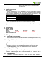
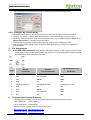
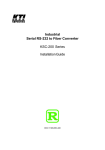
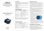
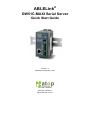
ABLELink®
GW51C-MAXI Serial Server
Quick Start Guide
Version 1.2
Updated on September, 2007
TEL: 886-3-5508137
FAX: 886-3-5508131
http://www.atop.com.tw
Quick Start Guide Version 1.2
GW51C-MAXI Serial Server
This document is intended to provide customers with brief descriptions on the product and to assist
customers to get started. For detail information and operations of the product, please refer to the user’s
manual in the product CD.
1.
Packaging
GW51C-MAXI Serial Server
Warranty Booklet
Quick Start Guide
Product CD
Mini DIN to RS-232 DB-9 Cable
Optional Accessories:
Power Adapter with Terminal block output 12V1.25A
(1) US315-12 (US) Switching adapter
(2) US315-12 (EU) Switching adapter
UL Notice for Power supplier
All the series of GW products are intended to be supplied by a Listed Power Unit marked with “LPS”, “Limited
Power Source” or “Class 2” and output rate 9~30VDC, 0.3A minimum. Or, use the recommended power
supply in “Optional Accessories”.
2.
Hardware Description
2.1. Interfaces
Fig.1 shows the interfaces of Serial Server’s Connectors、LEDs & the factory switch settings.
LED
Indicator
Mode Switch
Mini-Din Pin
Assignment
Serial Port Mini DIN
Connector
Mode Switch
Table
Serial Port
Terminal Block
Connector
UTP
Connector
Power Supply Input
Connector
Fig 1. Front Plate of GW51C-MAXI Serial Server
Note: One can press the reset button for 3 second to reset the settings to default value
2.2. LED Indications
2.2.1. LAN LED Message
Message
Description
LED Off
No data is transmitting on Ethernet
LED blinking
Data is transmitting on Ethernet
2.2.2. COM Port LED Message
Message
Description
LED off
No data is transmitting on COM port
LED on blinking state
Data is transmitting on COM port
2.2.3. RUN LED Message
Message
Description
1
Quick Start Guide Version 1.2
GW51C-MAXI Serial Server
LED on
Jumper JP1 pin1 and pin2 are short to disable AP firmware in
the flash memory.
LED blinking (rate: 0.5Sec)
AP firmware is running
3.
Installation Procedures
MODE Switch
This sets or initializes operating mode for the Serial Server. The factory default setting is that Switch
1 (SW1) and Switch 2 (SW2) are set to OFF. One can use the Mode switch to change the operating
mode from the factory default settings to ones desired mode.GW51C-MAXI Serial Server can be setup
either RS-232, RS-485, RS-422 or Console configuration mode by MODE Switch.
SW1
SW2
Mode
OFF
OFF
RS-232
ON
CONSOLE
ON
OFF
RS-485
ON
RS-422
Table 1. MODE Switch Combinations
Plug in Serial Server to DC-9-30V power source with 3-pin terminal block connector.
Connect Serial Server to ones Ethernet network. Use a standard straight-through Ethernet cable.
Connect Serial Server’s serial port to a serial device; make sure the connector and wiring of
RS-232 or RS-485 is correct.
Note: Buzzer will beep and the RUN LED will blink if Serial Server’s functions normally.
4.
Software Setup
4.1. Default Settings
Default IP address:
Interface
Ethernet port
Device IP
10.0.0.50.100
Subnet mask
Gateway IP
255.255.0.0
10.0.0.254
Password
Null (leave it blank)
Default User Name/Password:
User Name
admin
4.2. IP Assignment
4.2.1. Configure by monitor.exe Utility
Use monitor.exe that comes with product CD to automatically search all serial Server that connected
to ones local area network. Then select the desired Serial Server to configure the network setting
individually. Please refer to Appendix in the product user manual for more details.
4.2.2. Configure by Web Server
Use Web browser to configure the network parameters of Serial Server. Please refer to contents of
Appendix in the product user manual for more details.
Make sure ones PC is located on the same network subnet as Serial Server
Open web browser, then enter in the IP address (default IP:10.0.50.100) of Serial Server
Serial Server’s network, link mode and COM ports settings can be configured in web pages.
Click “Save Configuration” and then Click ”Restart” button to make the change effective.
4.2.3. Configure by Telnet Utility
Use Telnet utility (ex. Microsoft Hyper terminal ) to configure the network parameters of Serial Server.
Telnet to Serial Server using command “telnet IP_address”. Example:telnet 10.0.50.100.
Network, COM port settings can be configured individually. The configuration shall be
activated after saved settings and restart.
4.2.4. Auto IP with DHCP
A DHCP server can automatically assigns the IP address and network settings. Serial Server
supports DHCP client function. By default, the DHCP client function on Serial Server is disabled; one
2
Quick Start Guide Version 1.2
GW51C-MAXI Serial Server
may use Monitor.exe to activate this function. Please refer to the dialog window below.
4.2.5. Configure by console mode
1. Set MODE switch SW1 to ‘OFF’ and SW2 to ‘ON’, then Power off GW51C-MAXI Serial Server
2. Use a PC to connect to GW51C-MAXI Serial Server’s console with RS-232 cross over cable
3. Power on Serial Server, then Open terminal program from your computer and Set to 9600, 8, n, 1
without flow control for console port communication.
4. The following configuration operations are totally the same as those configure by telnet.
5. After finishing console settings, power off GW51C-MAXI Serial Server, put SW1 and SW2 back to
previous setting.
5.
Pin Assignments
5.1. 8 pin Mini DIN connector -Atop provides Mini DIN connector to DB9 connector cable, the pin
assignments is shown in the following table and RS-485 2 or 4 pins assignments of DB9 connector
are different from those of Mini DIN connector.
Pin#
6.
RS-232
RS-485
RS-422/RS-485 4 wire,
Full Duplex
2 wire, Half Duplex
Full Duplex
1
DCD
N/A
N/A
2
RXD
N/A (reserved)
TXD+
3
TXD
DATA+
RXD+
4
DTR
N/A
N/A
5
SG (Signal Ground)
SG (Signal Ground)
SG (Signal Ground)
6
DSR
N/A
N/A
7
RTS
DATA-
RXD-
8
CTS
N/A (reserved)
TXD-
9
N/A
N/A
N/A
Customer Services and Supports
Contact your local dealers or ATOP Technical Support Center at the following numbers.
+886-3-550-8137
(ATOP Taiwan)
+86-21-6495-6232
(ATOP China)
Report the errors via Atop’s Web site or E-mail account
www.atop.com.tw, [email protected]
www.atop.com.cn, [email protected]
3