1
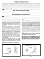
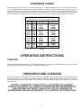
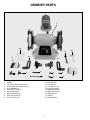
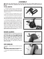
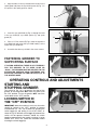
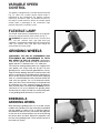
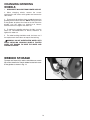
(Model GR250)
PART NO. 905595 - 05-03-02
Copyright © 2002 Delta Machinery
To learn more about DELTA MACHINERY
visit our website at: www.deltamachinery.com.
For Parts, Service, Warranty or other Assistance,
please call
ESPAÑOL: PÁGINA 13
1-800-223-7278 (In Canada call 1-800-463-3582).
INSTRUCTION MANUAL
6" Variable Speed
Grinder / Sharpener
GENERAL SAFETY RULES
Woodworking can be dangerous if safe and proper operating procedures are not followed. As with all machinery, there
are certain hazards involved with the operation of the product. Using the machine with respect and caution will
considerably lessen the possibility of personal injury. However, if normal safety precautions are overlooked or ignored,
personal injury to the operator may result. Safety equipment such as guards, push sticks, hold-downs, featherboards,
goggles, dust masks and hearing protection can reduce your potential for injury. But even the best guard won’t make
up for poor judgment, carelessness or inattention. Always use common sense and exercise caution in the workshop.
If a procedure feels dangerous, don’t try it. Figure out an alternative procedure that feels safer. REMEMBER: Your
personal safety is your responsibility.
This machine was designed for certain applications only. Delta Machinery strongly recommends that this machine not
be modified and/or used for any application other than that for which it was designed. If you have any questions relative
to a particular application, DO NOT use the machine until you have first contacted Delta to determine if it can or should
be performed on the product.
Technical Service Manager
Delta Machinery
4825 Highway 45 North
Jackson, TN 38305
(IN CANADA: 505 SOUTHGATE DRIVE, GUELPH, ONTARIO N1H 6M7)
WARNING: FAILURE TO FOLLOW THESE RULES MAY RESULT IN SERIOUS PERSONAL INJURY
1. FOR YOUR OWN SAFETY, READ INSTRUCTION
MANUAL BEFORE OPERATING THE TOOL. Learn the
tool’s application and limitations as well as the specific
hazards peculiar to it.
2. KEEP GUARDS IN PLACE and in working order.
3. ALWAYS WEAR EYE PROTECTION. Wear safety
glasses. Everyday eyeglasses only have impact resistant
lenses; they are not safety glasses. Also use face or dust
mask if cutting operation is dusty. These safety glasses
must conform to ANSI Z87.1 requirements. NOTE:
Approved glasses have Z87 printed or stamped on them.
4. REMOVE ADJUSTING KEYS AND WRENCHES. Form
habit of checking to see that keys and adjusting wrenches
are removed from tool before turning it “on”.
5. KEEP WORK AREA CLEAN. Cluttered areas and
benches invite accidents.
6. DON’T USE IN DANGEROUS ENVIRONMENT. Don’t
use power tools in damp or wet locations, or expose them
to rain. Keep work area well-lighted.
7. KEEP CHILDREN AND VISITORS AWAY. All children
and visitors should be kept a safe distance from work area.
8. MAKE WORKSHOP CHILDPROOF – with padlocks,
master switches, or by removing starter keys.
9. DON’T FORCE TOOL. It will do the job better and be
safer at the rate for which it was designed.
10. USE RIGHT TOOL. Don’t force tool or attachment to
do a job for which it was not designed.
11. WEAR PROPER APPAREL. No loose clothing, gloves,
neckties, rings, bracelets, or other jewelry to get caught in
moving parts. Nonslip footwear is recommended. Wear
protective hair covering to contain long hair.
12. SECURE WORK. Use clamps or a vise to hold work
when practical. It’s safer than using your hand and frees
both hands to operate tool.
13. DON’T OVERREACH. Keep proper footing and
balance at all times.
14. MAINTAIN TOOLS IN TOP CONDITION. Keep tools
sharp and clean for best and safest performance. Follow
instructions for lubricating and changing accessories.
15. DISCONNECT TOOLS before servicing and when
changing accessories such as blades, bits, cutters, etc.
16. USE RECOMMENDED ACCESSORIES. The use of
accessories and attachments not recommended by Delta
may cause hazards or risk of injury to persons.
17. REDUCE THE RISK OF UNINTENTIONAL STARTING.
Make sure switch is in “OFF” position before plugging in
power cord. In the event of a power failure, move switch
to the “OFF” position.
18. NEVER STAND ON TOOL. Serious injury could occur if
the tool is tipped or if the cutting tool is accidentally
contacted.
19. CHECK DAMAGED PARTS. Before further use of the
tool, a guard or other part that is damaged should be
carefully checked to ensure that it will operate properly and
perform its intended function – check for alignment of
moving parts, binding of moving parts, breakage of parts,
mounting, and any other conditions that may affect its
operation. A guard or other part that is damaged should be
properly repaired or replaced.
20. DIRECTION OF FEED. Feed work into a blade or
cutter against the direction of rotation of the blade or cutter
only.
21. NEVER LEAVE TOOL RUNNING UNATTENDED.
TURN POWER OFF. Don’t leave tool until it comes to a
complete stop.
22. STAY ALERT, WATCH WHAT YOU ARE DOING, AND
USE COMMON SENSE WHEN OPERATING A POWER
TOOL. DO NOT USE TOOL WHILE TIRED OR UNDER
THE INFLUENCE OF DRUGS, ALCOHOL, OR
MEDICATION. A moment of inattention while operating
power tools may result in serious personal injury.
23. MAKE SURE TOOL IS DISCONNECTED FROM
P O W E R S U P P LY w h i l e m o t o r i s b e i n g m o u n t e d ,
connected or reconnected.
24. THE DUST GENERATED by certain woods and wood
products can be injurious to your health. Always operate
machinery in well ventilated areas and provide for proper
dust removal. Use wood dust collection systems whenever
possible.
25.
WARNING: SOME DUST CREATED BY
POWER SANDING, SAWING, GRINDING, DRILLING,
AND OTHER CONSTRUCTION ACTIVITIES contains
chemicals known to cause cancer, birth defects or other
reproductive harm. Some examples of these chemicals
are:
· lead from lead-based paints,
· crystalline silica from bricks and cement and other
masonry products, and
· arsenic and chromium from chemically-treated lumber.
Your risk from these exposures varies, depending on how
often you do this type of work. To reduce your exposure
to these chemicals: work in a well ventilated area, and
work with approved safety equipment, such as those
dust masks that are specially designed to filter out
microscopic particles.
SAVE THESE INSTRUCTIONS.
Refer to them often and use them to instruct others.
2
ADDITIONAL SAFETY RULES FOR
GRINDERS
WARNING: FAILURE TO FOLLOW THESE RULES MAY RESULT IN SERIOUS PERSONAL INJURY.
15. NEVER GRIND NEAR FLAMMABLE GAS OR
LIQUIDS. Sparks can create a fire or an explosion.
1. DO NOT OPERATE THIS MACHINE until it is
assembled and installed according to the
instructions.
16. AVOID AWKWARD OPERATIONS AND HAND
POSITIONS where a sudden slip could cause a
hand to move into the grinding wheel.
2. OBTAIN ADVICE FROM YOUR SUPERVISOR,
instructor, or another qualified person if you are
not familiar with the operation of this machine.
17. KEEP ARMS, HANDS, AND FINGERS away from
the grinding wheel.
3. FOLLOW ALL WIRING CODES and recommended
electrical connections.
18. HOLD WORK FIRMLY against the tool rests.
4. USE THE GUARDS WHENEVER POSSIBLE.
Check to see that they are in place, secured, and
working correctly.
19. DRESS THE GRINDING WHEEL on the face only.
Dressing the side of the grinding wheel could cause
it to become too thin for safe use.
5. ALWAYS USE THE BLOTTER (furnished) and wheel
flanges to mount the grinding wheels on the grinder
shaft.
20. GRIND A WORKPIECE using the face of the
grinding wheel only.
21. NEVER APPLY COOLANT directly to the grinding
wheel. Coolant can weaken the bonding strength of
the grinding wheel and cause it to fail. Dip the
workpiece in water to cool it.
6. USE ONLY GRINDING WHEELS suitable for the
speed of the machine.
7. USE ONLY GRINDING WHEELS that have a bore
exactly equal to the arbors of the machine. Never
attempt to machine an undersized wheel to fit an
arbor.
22. DO NOT TOUCH the ground portion of a workpiece
until it has cooled sufficiently. Grinding creates heat.
23. TURN THE MACHINE “OFF” AND DISCONNECT
THE MACHINE from the power source before
installing or removing accessories, before adjusting
or changing set-ups, or when making repairs.
8. DO NOT USE A GRINDING WHEEL THAT
VIBRATES. Dress the grinding wheel, replace it, or
replace the bearings of the shaft.
24.. TURN THE MACHINE “OFF”, disconnect the
machine from the power source, and clean the
table/work area before leaving the machine. If your
machine has a switch lock-out feature, LOCK THE
SWITCH IN THE “OFF” POSITION to prevent
unauthorized use.
9. INSPECT GRINDING WHEELS BEFORE STARTING THE MACHINE for cracks or chips. REPLACE
DAMAGED GRINDING WHEELS immediately.
10. ADJUST SPARK GUARDS close to the grinding
wheel, and re-adjust as the wheel wears down.
11. ADJUST TOOL RESTS close to the grinding wheel
(1/8" (3.8mm) separation or less). Tighten the tool
rest securely to prevent shifting positions.
25. ADDITIONAL INFORMATION regarding the safe
and proper operation of this tool is available from
the Power Tool Institute, 1300 Summer Avenue,
Cleveland, OH 44115-2851. Information is also
available from the National Safety Council, 1121
Spring Lake Drive, Itasca, IL 60143-3201. Please
refer to the American National Standards Institute
ANSI 01.1 Safety Requirements for Woodworking
Machines and the U.S. Department of Labor OSHA
1910.213 Regulations.
12. STAND TO ONE SIDE before turning the machine
“ON”.
13. NEVER GRIND ON A COLD GRINDING WHEEL.
Run the grinder at idle speed for one full minute
before applying the workpiece.
14. NEVER START THE MACHINE with the workpiece
against the grinding wheel.
SAVE THESE INSTRUCTIONS.
Refer to them often
and use them to instruct others.
3
POWER CONNECTIONS
A separate electrical circuit should be used for your machines. This circuit should not be less than #12 wire and should
be protected with a 20 Amp time lag fuse. If an extension cord is used, use only 3-wire extension cords which have 3prong grounding type plugs and matching receptacle which will accept the machine’s plug. Before connecting the
motor to the power line, make sure the switch is in the “OFF” position and be sure that the electric current is of the
same characteristics as indicated on the machine. All line connections should make good contact. Running on low
voltage will damage the motor.
WARNING: DO NOT EXPOSE THE MACHINE TO RAIN OR OPERATE THE MACHINE IN DAMP LOCATIONS.
MOTOR SPECIFICATIONS
Your machine is wired for 120 volt, 60 HZ alternating current. Before connecting the machine to the power source,
make sure the switch is in the “OFF” position.
GROUNDING INSTRUCTIONS
WARNING: THIS MACHINE MUST BE GROUNDED WHILE IN USE TO PROTECT THE OPERATOR FROM
ELECTRIC SHOCK.
1. All grounded, cord-connected machines:
2. Grounded, cord-connected machines intended for use
on a supply circuit having a nominal rating less than 150
In the event of a malfunction or breakdown, grounding
volts:
provides a path of least resistance for electric current to
reduce the risk of electric shock. This machine is
If the machine is intended for use on a circuit that has an
equipped with an electric cord having an equipmentoutlet that looks like the one illustrated in Fig. A, the
grounding conductor and a grounding plug. The plug must
machine will have a grounding plug that looks like the plug
be plugged into a matching outlet that is properly installed
illustrated in Fig. A. A temporary adapter, which looks like
and grounded in accordance with all local codes and
the adapter illustrated in Fig. B, may be used to connect
ordinances.
this plug to a matching 2-conductor receptacle as shown
in Fig. B if a properly grounded outlet is not available. The
Do not modify the plug provided - if it will not fit the outlet,
temporary adapter should be used only until a properly
have the proper outlet installed by a qualified electrician.
grounded outlet can be installed by a qualified electrician.
Improper connection of the equipment-grounding
The green-colored rigid ear, lug, and the like, extending
conductor can result in risk of electric shock. The
from the adapter must be connected to a permanent
conductor with insulation having an outer surface that is
ground such as a properly grounded outlet box. Whenever
green with or without yellow stripes is the equipmentthe adapter is used, it must be held in place with a metal
grounding conductor. If repair or replacement of the
screw.
electric cord or plug is necessary, do not connect the
equipment-grounding conductor to a live terminal.
NOTE: In Canada, the use of a temporary adapter is not
permitted by the Canadian Electric Code.
Check with a qualified electrician or service personnel if
t h e g ro u n d i n g i n s t r u c t i o n s a re n o t c o m p l e t e l y
understood, or if in doubt as to whether the machine is
WARNING: IN ALL CASES, MAKE CERTAIN THE
properly grounded.
RECEPTACLE IN QUESTION IS PROPERLY
G R O U N D E D . I F Y O U A R E N O T S U R E H AV E A
Use only 3-wire extension cords that have 3-prong
QUALIFIED ELECTRICIAN CHECK THE RECEPTACLE.
grounding type plugs and matching 3-conductor
receptacles that accept the machine’s plug, as shown in
Fig. A.
Repair or replace damaged or worn cord immediately.
GROUNDED OUTLET BOX
GROUNDED OUTLET BOX
GROUNDING
MEANS
CURRENT
CARRYING
PRONGS
ADAPTER
GROUNDING BLADE
IS LONGEST OF THE 3 BLADES
Fig. A
4
Fig. B
EXTENSION CORDS
Use proper extension cords. Make sure your extension cord is in good condition and is a 3-wire extension cord which
has a 3-prong grounding type plug and matching receptacle which will accept the machine’s plug. When using an
extension cord, be sure to use one heavy enough to carry the current of the machine. An undersized cord will cause
a drop in line voltage, resulting in loss of power and overheating. Fig. D, shows the correct gauge to use depending
on the cord length. If in doubt, use the next heavier gauge. The smaller the gauge number, the heavier the cord.
MINIMUM GAUGE EXTENSION CORD
RECOMMENDED SIZES FOR USE WITH STATIONARY ELECTRIC MACHINES
Ampere
Rating
Volts
Total Length
of Cord in Feet
Gauge of
Extension Cord
0-6
0-6
0-6
0-6
120
120
120
120
up to 25
25-50
50-100
100-150
18 AWG
16 AWG
16 AWG
14 AWG
6-10
6-10
6-10
6-10
120
120
120
120
up to 25
25-50
50-100
100-150
18 AWG
16 AWG
14 AWG
12 AWG
10-12
10-12
10-12
10-12
120
120
120
120
up to 25
25-50
50-100
100-150
16 AWG
16 AWG
14 AWG
12 AWG
12-16
12-16
12-16
120
120
120
up to 25
25-50
14 AWG
12 AWG
GREATER THAN 50 FEET NOT RECOMMENDED
Fig. D
OPERATING INSTRUCTIONS
FOREWORD
The Delta ShopMaster Model GR250 is a 6"Variable Speed Grinder / Sharpener. The Model GR250 comes with a flexible
lamp, adjustable tool rests, and two large eye shields for added safety.
UNPACKING AND CLEANING
Carefully unpack the machine and all loose items from the shipping container(s). Remove the protective coating from
all unpainted surfaces. This coating may be removed with a soft cloth moistened with kerosene (do not use acetone,
gasoline or lacquer thinner for this purpose). After cleaning, cover the unpainted surfaces with a good quality household
floor paste wax.
NOTICE: THE MANUAL COVER PHOTO ILLUSTRATES THE CURRENT
PRODUCTION MODEL. ALL OTHER ILLUSTRATIONS ARE REPRESENTATIVE
ONLY AND MAY NOT DEPICT THE ACTUAL COLOR, LABELING OR
ACCESSORIES AND MAY BE INTENDED TO ILLUSTRATE TECHNIQUE ONLY.
5
GRINDER PARTS
1
10
18
17
12
11
15
14
13
6
5
7
8
4
3
Fig. 2
1.
2.
3.
4.
5.
6.
7.
8.
9.
Grinder
1/4-20x1/4" hex head screw (2)
5/16-18x5/8" hex head screw (4)
Eye shield bolt (2)
5/16-18x3/4" knob (2)
Eye shield knob (2)
Eye shield spacer (2)
5/16" flat washer (6)
1/4" flat washer (4)
10.
11.
12.
13.
14.
15.
16.
17.
18.
6
Eye shield (2)
Left tool rest
Left tool rest arm
Left spark guard
Right spark guard
Right tool rest arm
Right tool rest
Wrench
Wheel dresser
9
2
16
ASSEMBLY
WARNING: FOR YOUR OWN SAFETY, DO NOT CONNECT THE TOOL TO THE POWER SOURCE UNTIL THE
MACHINE IS COMPLETELY ASSEMBLED AND YOU READ AND UNDERSTAND THE ENTIRE INSTRUCTION
MANUAL.
TOOL RESTS
C
1. Assemble left tool rest (A) Fig. 3, to left tool rest arm
(B), as shown, and fasten with one 5/16-18x3/4" knob
(C) and 5/16" flat washer (D). Assemble the remaining
tool rest in the same manner. Do not completely tighten
hardware at this time.
A
2. Assemble left tool rest assembly (D) Fig. 4, to the
inside of left wheel guard (E), and fasten with two 5/1618x5/8" screws (F) and 5/16" flat washers (G) as shown.
D
B
3. Assemble right tool rest assembly to the inside of
right wheel guard and fasten with two 5/16-18x5/8" hex
head screws and 5/16" flat washers in the same manner.
Fig. 3
4. Each tool rest assembly (D) Fig. 4, is adjustable so it
can be positioned slightly below the centerline of the
wheel and as close to the grinding wheel as possible,
giving maximum support to the piece that is being
ground. Always maintain a distance of 1/8" or less
between the grinding wheel and the inside edge of the
tool rest. As the wheels wear down, the tool rest should
be adjusted accordingly. When the tool rest is positioned
correctly, tighten hardware (C) and (F). Freehand
grinding without the use of a tool rest should always be
done on the lower quarter of the wheel.
G
D
C
F
E
Fig. 4
SPARK GUARDS
C
The spark guard (A) Fig. 5, is mounted to the side of each
wheel guard, using a 1/4-20x1/4" hex head screw (B)
and 1/4" flat washer (C) as shown. NOTE: The tab (D)
Fig. 5, on the side of the spark guard (A), must be
placed in slot (E), before attaching the spark guard
(A) to the grinder. The spark guard (A) should be
adjusted as close as possible to the grinding wheel so
that sparks never strike the operator’s hand. As the
wheels wear down, the spark guard (A) should be
adjusted accordingly.
B
A
D
E
Fig. 5
EYE SHIELDS
Your grinder is supplied with two eye shields for operator
protection.
WARNING: ALWAYS WEAR EYE PROTECTION. To
assemble the eye shields, proceed as follows:
A
1. Place the eye shield (A) on the spark guard as shown
in Fig. 6.
Fig. 6
7
2. Align the holes in the eye shield with the holes in the
spark guard and place the eye shield spacer (A) Fig. 7, in
the space in the spark guard as shown.
A
Fig. 7
D
C
3. Insert the eye shield bolt (A) Fig. 8, through the hole
in the eye shield (B), eye shield spacer (C), and spark
guard (D).
E
F
A
4. Place a 1/4" flat washer (E) Fig. 8, onto the end of the
eye shield bolt and fasten the eye shield knob (F) to the
end of the eye shield bolt.
B
5. Assemble the other eye shield in the same manner.
Fig. 8
FASTENING GRINDER TO
SUPPORTING SURFACE
IF DURING OPERATION THERE IS ANY TENDENCY
FOR THE GRINDER TO TIP OVER, SLIDE OR
“WALK,” THE GRINDER MUST BE SECURED TO THE
SUPPORTING SURFACE USING FASTENERS (NOT
SUPPLIED) THROUGH THE TWO HOLES (A) Fig. 9, IN
THE GRINDER BASE.
A
A
Fig. 9
OPERATING CONTROLS AND ADJUSTMENTS
STARTING AND
STOPPING GRINDER
The switch (A) Fig. 10, is located on the front of the
grinder. To turn the grinder “ON” move the switch up to
the “ON” position. To turn the grinder “OFF” move the
switch down to the “OFF” position.
LOCKING SWITCH IN
THE “OFF” POSITION
IMPORTANT: When the machine is not in use, the switch
should be locked in the “OFF” position to prevent
unauthorized use. This can be done by grasping the
switch toggle (A) and pulling it out of the switch, as
shown in Fig. 10. With the switch toggle (A) removed, the
switch will not operate. However, should the switch
toggle be removed while the sander is running, it can be
turned “OFF” once, but cannot be restarted without
inserting the switch toggle (A).
A
B
Fig. 10
8
VARIABLE SPEED
CONTROL
The grinder is equipped with a variable speed control (B)
Fig. 10. When the variable speed control knob is
positioned to the furthermost left position (counter
clockwise), the RPM is 2000. The rotation increases as
the knob is turned clockwise. When the variable speed
control knob is positioned to the furthermost right
position (clockwise), the RPM is 3450.
FLEXIBLE LAMP
A
The flexible lamp operates independently of the grinder.
To turn the lamp on and off, rotate switch (A) Fig. 11.
WARNING: To reduce the risk of fire, use 40 watt or
less, 120 volt, reflector track type light bulb (not
supplied). A standard household light bulb should not be
used. The reflector track type light bulb should not
extend below the lamp shade.
GRINDING WHEELS
Fig. 11
WARNING: THE USE OF ACCESSORIES AND
ATTACHMENTS NOT RECOMMENDED BY DELTA
MAY RESULT IN RISK OF INJURIES. Attachments
used with this grinder should be rated for 3600 RPM or
higher and be 6" in diameter with a 1/2" arbor hole.
Two aluminum oxide grinding wheels are supplied with
your grinder; one 36 grit and one 60 grit. For best
grinding results, and to maintain good balance, always
keep the wheels properly dressed. Do not force the work
against a cold wheel. The grinding wheel should always
be run at idle speed for one full minute before applying
work. It is recommended that only balanced wheels be
used with your grinder. The use of balanced wheels
adds years to the life of the bearings on the grinder and
by eliminating the most common source of vibration,
more accurate work is accomplished. ALWAYS maintain
a distance of 1/8" or less between the grinding wheel
and the tool rest. Adjust the tool rests and spark guards
as the grinding wheels decrease in size with use.
DRESSING A
GRINDING WHEEL
When dressing a grinding wheel, use a suitable silicone
carbide stick type dresser or the wheel dresser provided
with the grinder, as shown in Fig. 12. Bring the dresser
forward on the tool rest until it just touches the high point
on the face of the wheel and dress the wheel by moving
the dresser back and forth. Repeat this operation until
the face of the grinding wheel is clean and the corners of
the wheels are square.
Fig. 12
9
CHANGING GRINDING
WHEELS
1. DISCONNECT MACHINE FROM POWER SOURCE.
2. When changing wheels, remove the screws
attaching the side covers to the grinder and remove the
side covers.
3. To prevent shaft rotation, place a wedge between the
grinding wheel and the tool rest. NOTE: Facing the front
of the grinder: to replace the wheel on the left side of the
grinder, turn the arbor nut clockwise to loosen;
counterclockwise to tighten the arbor nut.
4. To replace the grinding wheel on the right, turn the
arbor nut, counterclockwise to loosen; clockwise to
tighten the arbor nut.
5. The arbor bushing should be saved, for future use, if
the replacement wheel does not require the bushing.
WARNING: DO NOT OVERTIGHTEN WHEEL NUTS
WHEN INSTALLING GRINDING WHEELS. TIGHTEN
WHEEL NUT ENOUGH TO DRIVE THE WHEEL AND
PREVENT SLIPPAGE.
WRENCH STORAGE
A
The open end wrench (A) and the wheel dresser wrench
(B) can be stored in the wrench holder located at the rear
of the grinder as shown in Fig. 13.
B
Fig. 13
10
NOTES
11
ACCESSORIES
A complete line of accessories is available from your Delta Supplier, Porter-Cable • Delta Factory Service Centers,
and Delta Authorized Service Stations. Please visit our Web Site www.deltamachinery.com for a catalog or
for the name of your nearest supplier.
WARNING: Since accessories other than those offered by Delta have not been tested
with this product, use of such accessories could be hazardous. For safest operation, only
Delta recommended accessories should be used with this product.
PARTS, SERVICE OR WARRANTY ASSISTANCE
All Delta Machines and accessories are manufactured to high quality standards and are serviced by a network
of Porter-Cable • Delta Factory Service Centers and Delta Authorized Service Stations. To obtain additional
information regarding your Delta quality product or to obtain parts, service, warranty assistance, or the location
of the nearest service outlet, please call 1-800-223-7278 (In Canada call 1-800-463-3582).
Two Year Limited Warranty
Delta will repair or replace, at its expense and at its option, any Delta machine, machine part, or machine accessory which
in normal use has proven to be defective in workmanship or material, provided that the customer returns the product
prepaid to a Delta factory service center or authorized service station with proof of purchase of the product within two
years and provides Delta with reasonable opportunity to verify the alleged defect by inspection. Delta may require that
electric motors be returned prepaid to a motor manufacturer’s authorized station for inspection and repair or replacement.
Delta will not be responsible for any asserted defect which has resulted from normal wear, misuse, abuse or repair or
alteration made or specifically authorized by anyone other than an authorized Delta service facility or representative. Under
no circumstances will Delta be liable for incidental or consequential damages resulting from defective products. This
warranty is Delta’s sole warranty and sets forth the customer’s exclusive remedy, with respect to defective products; all
other warranties, express or implied, whether of merchantability, fitness for purpose, or otherwise, are expressly
disclaimed by Delta.
Printed in U.S.A.
12