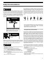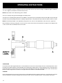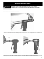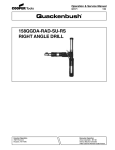
1
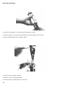
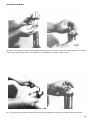
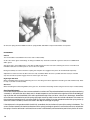
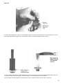
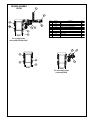
Operation & Service Manual
823172EN
04/11/2011
15QDA-RAB-SU-RS
Right Angle Positive Feed Drills
For additional product information visit our website at http://www.apextoolgroup.com
Safety Recommendations
For your safety and the safety of others, read and understand
the safety recommendations and operating instructions.
Always wear protective equipment:
!
WARNING
Impact resistant eye protection
must be worn while operating
or working near this tool.
For additional information on eye and face protection, refer to
Federal OSHA Regulations, 29 Code of Federal Regulations, Section 1910.133., Eye and Face Protection, and American National
Standards Institute, ANSI Z87.1, Occupational and Educational Eye
and Face Protection. Z87.1 is available from the American National
Standards Institute, Inc., 11 West 42nd Street, New York, N.Y.
10036.
!
CAUTION
Personal hearing protection is
recommended when operating
or working near this tool.
Hearing protection is recommended in high noise areas, 85 dBA or
greater. The operation of other tools and equipment in the area,
reflective surfaces, process noises and resonant structures can
substantially contribute to and increase the noise level in the area.
For additional information on hearing protection, refer to Federal
OSHA Regulations, 29 Code of Federal Regulations, Section 1910.95,
Occupational Noise Exposure, and American National Standards
Institute, ANSI S12.6, Hearing Protectors.
!
WARNING
Follow good machine shop
practices. Rotating shafts and
moving components entangle
and entrap, and may result in
serious injuries. Never wear
long hair, loose-fitting clothes,
gloves, ties, or jewelry when
working with or near a drill of
any type.
Do not wear loose fitting clothes,
long hair, gloves, ties or jewelry.
2
!
CAUTION
• Quackenbush drills are designed to operate on 90psig (6.2 bar)
air pressure. Excessive air pressure can increase the loads and
stresses on tool parts and drills, and may result in breakage. The
installation of a filter-regulator-lubricator in the air supply line is
highly recommended.
• Before removing a tool from service or changing drill bits, make
sure the air line is shut off and drained of air. This will prevent the
tool from operating if the throttle is accidently engaged.
• Cutting tools used with these Quackenbush drill motors are sharp.
Handle them carefully to avoid injury.
!
CAUTION
Before mounting any positive feed drill, check the lock screws in the
tooling fixture and drill bushing. Make sure both are in good condition
and securely tightened.
Lock Screws
Tool Nose
Standard Threaded
Drill Bushing
Tooling Fixture
Positive feed drills can exert high torques and high thrust loads. If
failure of the lock screws or drill bushing occurs, the drill may
suddenly spin and back away from the drill fixture.
Warning Labels
The warning labels found on these tools are essential parts of this
product. Labels should not be removed. Labels should be checked
periodically for legibility. Replace warning labels when missing or
when the information can no longer be read. Replacement labels
can be ordered from the manufacturer.
Safety Recommendations
!
CAUTION
The spindle on right angle positive feed drills retracts at a much
faster rate than it feeds. Care should be taken to avoid entrapment.
Nose pieces usually used with these drills are generally slotted for
visibility and access to chuck, cutter, and retract stop adjustments.
A spindle guard should be used when operating tool. Spindle
guards in one inch increments are available to accommodate any
length spindle. Slotted spindle guards are available for tools with
fluid swivels.
Some individuals are susceptible to disorders of the hands and arms
when exposed to tasks which involve repetitive work motions. Those
individuals predisposed to vasculatory or circulatory problems may
be particularly susceptible. Cumulative trauma disorders such as
carpal tunnel syndrome and tendinitis may be caused or aggravated
by repetitious, forceful exertions of the hands and arms. These
disorders develop gradually over periods of weeks, months, and
years.
Avoid
OK
Avoid
Avoid
OK
Avoid
Neutral
Ulnar Deviation
WARNING
!
Extension
Neutral
Flexion
Radial Deviation
• Tasks should be performed in such a manner that the wrists
are maintained in a neutral position, which is not flexed,
hyperextended, or turned side to side.
Keep hands and fingers away from
slot in spindle guard and nose piece
• Stressful postures should be avoided and can be controlled
through tool selection and work location.
when handling or operating tool.
!
WARNING
Wear respirator where
necessary.
Drilling or other use of this tool may produce hazardous fumes and/
or dust. To avoid adverse health effects utilize adequate ventilation
and/or a respirator. Read the material safety data sheet for any
cutting fluids or materials involved in the drilling process.
!
WARNING
• Most dusts are combustible. See material safety data sheets for
combustibility of a specific dust.
• Non ferrous metal dusts are particularly haxardous.
Examples: Aluminum, Magnesium, Titanium, Zirconium
(Never collect Magnesium in a dry dust collector)
• Never collect spark generating material in the same dust collector
with combustible material.
Examples: Collecting both Steel and Aluminum dust or Steel and
Titanium dust.
• Never use flamable finishing lubricants.
Any tool operator should be aware of the following warning signs and
symptoms so that a problem can be addressed before it becomes a
debilitating injury. Any user suffering prolonged symptoms of tingling, numbness, blanching of fingers, clumsiness or weakened
grip, nocturnal pain in the hand, or any other disorder of the
shoulders, arms, wrists, or fingers is advised to consult a physician.
If it is determined that the symptoms are job related or aggravated
by movements and postures dictated by the job design, it may be
necessary for the employer to take steps to prevent further occurrences. These steps might include, but are not limited to, repositioning the workpiece or redesigning the workstation, reassigning workers to other jobs, rotating jobs, changing work pace, and/or changing
the type of tool used to minimize stress on the operator. Some tasks
may require more than one type of tool to obtain the optimum
operator/tool/task relationship.
The following recommendations will help reduce or moderate the
effects of repetitive work motions. The operator of any drill should:
• Use a minimum hand grip force consistent with proper control and
safe operation
• Keep body and hands warm and dry
• Avoid anything that inhibits blood circulation
— Smoking Tobacco
— Cold Temperatures
— Certain Drugs
• Avoid awkward postures
• Keep wrists as straight as possible
• Interrupt work activities, or rotate jobs to provide periods free from
repetitive work motions.
3
OPERATING INSTRUCTIONS
The tool is designed to operate on 90 psig air pressure using a 3/8" l.D. hose up to 8 feet in length. If additional length is required, a
1/2 " l.D. or larger hose should be connected to the 3/8" hose.
NOTE: Safety Labels can be ordered using part no. 202691.
The tool is started by turning the Throttle Ring A to the "ON" position.
The feed cycle is started by pushing the Retract Lever B down. The spindle may be controlled by the Automatic Stop D or it may be manually
retracted at any point by pulling the Retract Lever B up. Rapid retraction of the spindle takes place while the spindle continues to rotate.
NOTE: The Gear Stop 622985, can be adjusted by turning the two 1/8" hex set screws 867502 C, on either side of the angle head.
Before installing or removing a cutting tool, or such accessory, be sure the tool is disconnected from the air supply. If the air supply line has
a valve, shut the valve off and bleed off the air in the line.
LUBRICATlON
An automatic in-line filter-regulator-lubricator is recommended as it increases tool life and keeps the tool in sustained operation. The inline lubricator should be regularly checked and filled worth a good grade of 10W machine oil. Proper adjustment of the in-line lubricator is
performed by placing a sheet of paper next to the exhaust ports and holding the throttle open approximately 30 seconds. The lubricator is
properly set when a light stain of oil collects on the paper. Excessive amounts of oil should be avoided.
STORAGE
In the event that it becomes necessary to store the tool for an extended period of time (overnight, weekend, etc.), it should receive a generous
amount of lubrication at that time and again when returned to service. The tool should be stored in a clean and dry environment.
4
SERVICE INSTRUCTIONS
!
WARNING
Eye protection must be worn when disassembling tool or when air line is turned on.
A self relieving valve in close proximity to the repair station to bleed off air is recommended.
DRILL HEAD DISASSEMBLY
Turn off and bleed air line. Disconnect tool from air line.
1. Clamp tool in soft jawed vise and remove spindle guard with strap wrench and nose piece with appropriate wrench (left hand threads).
2. Remove front stop collar 617962, by loosening stop collar set screw 617785, with 5/64" hex wrench. Connect air and turn on tool. Start
feed cycle by pushing down retract lever. Spindle will feed out. Turn off and bleed off air line. Disconnect tool from air line.
5
3. Clamp drill head in soft jawed vise in a vertical position and remove drill head and drill head adapter 613544 (both left hand threads).
4. Remove drive coupling 622951. The spacer 617149, bearing 847095 and driving bevel gear 622947, will come out when drill head is
tapped on soft surface.
6
5. Insert spindle in front of drill head until it engages spindle drive gear 622950. Then with appropriate wrench 849902 remove drive gear
retainer screw 622976.
6. Remove four 7/64" socket head cap screws 863337 and lift off retract body 624094.
7
7. To remove lever from retract body, loosen the two ball plungers 622954, with screwdriver. Push lever pin 844111, out and drive roll pin
844787, with punch if needed to be replaced.
8. Remove two set screws 867502, with 1/8" hex wrench. This will release the two roller springs 844247 and four clutch rollers 622984.
Remove gear stop 622985, at this time also.
8
9. Loosen nose adapter and turn flats so two (6/32" X 3/8") flat head screws 863463, in cover 622974, can be removed. Then remove two
(6/32" X 5/8") flat head screws from other end of cover.
10. Remove cover 622974. Idler gear 622984, pinion and shaft 622952, driven bevel gear 622946 and bearing 847609, and idler gear
spacers 614574 (long) and 614575 (short) will come out at the same time.
9
11. Press drive gear needle bearing 847430, out if necessary. Installing new bearing, press bearing slightly below inside face of cover.
12. Press idler gear shaft 622980, out if necessary. Press new shaft flush with outside face of cover.
13. Press driven bevel gear 622946, out of bearing if necessary.
14. Remove two retainer rings 619016, to replace bearing 617980, in idler gear 622948.
15. Press pinion and shaft 622952, out of bearing if necessary.
10
16. Press differential drive gear 622949 and differential feed gear together and slip out of housing 622986.
17. Remove nose adapter (left hand threads), spindle drive gear 622950, spindle feed gear and spindle feed gear bearing 617168.
11
GEAR CASE DISASSEMBLY
18. Clamp gear case on large flats in vertical position. With appropriate wrench on flats loosen motor housing 613226.
19. Slip 1st reduction spider and bearing out rear of gear case.
12
20. Clamp gear case in vise and remove retainer ring 864240, with two screwdrivers.
21. Push 2nd reduction spider and bearing out of gear case. Remove retainer ring 844364, from front of gear case and remove bearing
843615. After removing the spider bearing with a suitable bearing puller, the idler gears may be removed by driving the idler gear pins out
the rear of the two spiders. Pinion gear 864239, which is used in the 1400 RPM gear train, can then be removed from the first reduction
spider.
13
MOTOR UNIT DISASSEMBLY
22. Clamp rotor shaft 864337, in vise and pull motor housing 613226, off motor.
23. Drive rotor 864337, out of front bearing plate 864235 and front bearing 844772, with soft mallet.
24. Remove cylinder 864236 and four rotor blades 864234.
25. Remove retainer ring 812231 and shims.
26. Drive rotor out of rear bearing plate 864232.
27. Remove bearings from bearing plates to check for wear.
14
BACKHEAD DISASSEMBLY
28. Remove exhaust deflector 612982, muffler 612983 and "O"-ring 617754, for inspection . Clamp hose adapter 624119, in vise and with
wrench loosen motor housing. Remove hose adapter and screen 613066, for inspection. Clean or replace.
29. To remove throttle ring 613263 and throttle parts. Remove pipe plug 843434 and retainer ring 613059, and lift off throttle ring.
15
30. Unscrew spring retainer 613060 and remove spring 613058, ball 844077 and push rod 613264, for inspection.
REASSEMBLY
General
The tool should be reassembled in the reverse order of disassembly.
As all of the various gears and bearings are being assembled, they should be coated with a generous amount of "LUBRIPLATE
#907" grease.
After power unit is reassembled, place a few drops of 10W machine oil in the hose before attaching the air hose. This will insure
immediate lubrication of all motor parts as soon as the air is applied.
During reassembly, be sure that the drive coupling hex and spline are engaged in the power unit and drill head respectively.
Adjustment of retract lever must be done after tool is fully assembled. When the lever is pushed down into feed cycle it should
stay there until the stop collar engages the lever and tool goes into retract.
Right Angle Drill Head
When reinstalling pinion and shaft and bearing into cover, the idler gear must be slipped onto the idler gear shaft simultaneously. Refer
to steps 13,14 and 15 in Disassembly.
Gear Case
When reinstalling the front bearing 843615, in the gear case, the shield on the bearing must be facing out. Refer to step 21 in Disassembly.
Gear Stop Adjustment
In order to make the adjustment, there are two methods that can be used. The preferred method is to make the adjustment during
assembly of drill before the retract body and its’ related components are attached to the angle head. With the 622985 gear
stop in position with and the 622984 clutch rollers positioned on top of the cam lobes, rather than in the detents, the 867502
set screws are turned clockwise until the springs just begin to make up solid, but are not crushed or distorted. The screws are
then rotated counterclockwise 45° minimum to 90° By using this method, it’s easier to determine when the spring makes up
solid so that there is tendency to force the screw in too deep and damage the springs.
If the adjustment is to be performed with the drill fully assembled, the clutch rollers will normally be resting in the detents. The
screws are then rotated in the clockwise direction until the springs just begin to go solid. Care must be used so as not to distort
the springs. Once the solid state is achieved, the set screws are backed out (counterclockwise) one full turn plus the 45° to 90°.
16
Motor Unit
31. When reassembling motor, measure rear bearing plate's inner face down to the bearing's inner race with micrometers. Cut new
rotor collar 843913 .0015" longer than this measurement. Install rotor collar in bearing plate chamfer side out.
32. After installing shims between retainer ring 812231 and rear rotor bearing to keep rotor collar tight against bearing. Check clearance between rotor and rear bearing plate. Clearance between rotor and bearing plate should be .0015".
33. Rotor blades should be replaced at every repair cycle or when any blade measures less than 7/32" at either end.
17
SPINDLE GUARD CAP
SPINDLE GUARD
RIGHT ANGLE
DRILL HEAD
863337
622973
624351
(Fluid Spindle Guard Only)
629545
Optional
Jam Nut
617962
617785
614576
624094
622954
617149
622951
844787
844111
622984
867502
622985
619685
847095
622947
867502
834228
613828
622984
619685
847095
622986
614574
622946
863463
617168
619016
622952
617980
622948
SPINDLE
FEED GEAR
623001
5
623002 10
622943 20
622942 30
623004 60
622950
847609
619016
614575
617993
842161
622980
622949
DIFFERENTIAL
FEED GEAR
623000
5
623003 10
622945 20
622944 30
623005 60
622400
865576
WRENCH - 849902
NOSE
ADAPTER
1 1/8"
622401
SPINDLE WRENCH - 622466
for 15, 158 & 230 RA Tools.
625092
8.00"
617166
847609
844306
622976
SPINDLE
617962
617785
18
629545
Optional
Jam Nut
PART LISTS — RIGHT ANGLE DRILL HEAD
PART NO.
613828
614574
614575
614576
617149
617166
617168
617785
617962
617980
617993
619016
619685
622400
622401
622942
622943
622944
622945
622946
622947
622948
622949
622950
622951
622952
622954
622973
622976
622980
622984
622985
622986
623000
623001
623002
623003
623004
623005
624094
624351
624355
625092
629545
834228
842161
844111
844306
844787
847095
847609
863337
863463
865576
867502
NAME OF PART
Name Plate
Idler Gear Spacer (Long)
Idler Gear Spacer (Short)
Angle Head Adapter
Spacer
Flat Head Screw (6/32" x 5/8")
Feed Gear Ball Bearing
Stop Collar Set Screw
Stop Collar
Ball Bearing
Spring
Retainer Ring
Roller Spring
Ball Bearing
Nose Adapter
.003" Spindle Feed Gear (32T)
.002" Spindle Feed Gear (40T)
.003" Differential Feed Gear (31T)
.002" Differential Feed Gear (38T)
Driven Bevel Gear
Driving Bevel Gear
Idler Gear
Differential Drive Gear
Spindle Drive Gear
Drive Coupling
Pinion & Shaft
Ball Plunger
Retract Lever
Drive Gear Retainer Screw
Idler Gear Shaft
Clutch Roller
Gear Stop
Housing
.0005" Differential Feed Gear (34T)
.0005" Spindle Feed Gear (37T)
.001" Spindle Feed Gear (43T)
.001" Differential Feed Gear (40T)
.006" Spindle Feed Gear (31T)
.006" Differential Feed Gear (32T)
Retract Body
Fluid Spindle Guard Shims (.010")
Spindle Guard Cap**
Cover
Jam Nut (Optional)
Drive Screw
Steel Ball (3/16")
Lever Pin
"O"-Ring 5/16" x 7/16"
Roll Pin
Bevel Gear Ball Bearing
Pinion Shaft & Drive Gear Ball Bearing
Socket Head Cap Screw
Flat Head Screw (6/32" x 3/8")
Thrust Race
Set Screw
**Included with Spindle Guards
QUANITY
Drill Head Assemblies
With Nose Adapter
622401 (1-20 L.H. Male Thread)
Feed
.0005"
.001"
.002"
.003"
.006"
Code No.
621615
621616
621617
621618
621619
1
1
1
1
1
2
1
2
2
1
1
2
2
1
1
1
1
1
1
1
1
1
1
1
1
1
2
1
1
1
4
1
1
1
1
1
1
1
1
1
1
1
1
2
2
1
1
1
1
2
2
4
2
1
2
19
RIGHT ANGLE GEAR TRAINS FOR POWER UNITS
SPINDLE SPEED
660
1000
1650
2000 864376
3000 864340
5000 864237
GEAR TRAINS
2000
3000
5000
2000 NONE
3000 NONE
5000 864239
2000 843615
3000 843615
5000 617699
844364
864241
2000 844774
3000 844774
5000 847183
843589
611534
SPINDLE SPEED
165
265
335
465
847146
2000 844779
3000 844799
5000 844081
2000 627720
3000 624127
5000 615960
GEAR TRAINS
500
800
1000
1400
500
800
1000
1400
847147
864376
864340
864323
864237
500
800
1000
1400
844774
844774
847183
847183
500
800
1000
1400
NONE
NONE
NONE
864239
844799
843589
843615
844364
20
500
800
1000
1400
864240
613544
864242
844773
613733
500
800
1000
1400
613760
864341
613761
864238
847147
844799
844799
844799
844081
RIGHT ANGLE MOTOR & MOTOR HOUSING
FOR POWER UNITS
500
800
1000
1400
2000
3000
5000
864660
864337
864338
864337
864660
864337
864337
812164
.001 864730
.002 864731
.003 864932
847095
864235
843913
844772
613227
812231
864232
864234
202632
629323
632532
613226
864737
629322
613058
613060
844077
631245
615674
843434
"A" Live air
all the time
B
A
613263
613063
625560
617409
844310
613059
613066
625561
613263
843434
"B" Live air
when tool is on
613264
812165
21
PARTS LIST — POWER UNIT
PART NO.
202632
611534
613058
613059
613060
613063
613066
613226
613227
613263
613264
613544
613733
613760
613761
615674
615960
617699
624119
624127
627720
629322
629323
631254
632532
812164
812165
812231
843434
843589
843615
843913
844077
844081
844364
844772
844773
844774
844799
847095
847146
847147
864232
864234
864235
864236
864237
864238
864239
864240
864241
864242
864323
864337
864338
864340
864341
864376
864660
864730
864731
864732
864737
22
NAME OF PART
MUFFLER
3000 RPM GEAR CASE (INCL. 846412, 613544, 843589)
SPRING
SPIRAL RETAINER RING
SPRING RETAINER
THROTTLE ROD BUSHING
INLET SCREEN
MOTOR HOUSING
BEARING CAP
THROTTLE RING
THROTTLE PUSH ROD
MOTOR ADAPTER (INCLUDED WITH 3000 RPM GEAR CASE)
500, 800, 1000, 1400 RPM GEAR CASE (INCL. 843589)
500 RPM 1ST RED. SPIDER
1000 RPM 1ST RED. SPIDER
THROTTLE HANDLE
5000 RPM SPIDER
BALL BEARING (5000 RPM ONLY)
INLET BUSHING
3000 RPM SPIDER
2000 RPM SPIDER
EXHAUST DEFLECTOR
MUFFLER
OPT. SWIVEL INLET (INCL. 617409, 625560, 844310 & 625561)
SCREEN
ROLL PIN
ROLL PIN
RETAINER RING
PIPE PLUG
GREASE FITTING
BALL BEARING
ROTOR COLLAR
5/16" DIA. STEEL BALL
1400 RPM 1ST RED. IDLER GEAR PIN
RETAINER RING
BALL BEARING
BALL BEARING
NEEDLE BEARING (INCLUDED IN 864376, 864340, 864323)
500, 800, 1000, 1400 RPM 2ND RED. AND 500, 800, 1000, 3000
1ST RED. IDLER GEAR PIN (3000 REQ. ONLY 2)
BALL BEARING
NEEDLE BEARING (INCLUDED IN 844799)
(3000 RPM REQ. ONLY 2)
BALL BEARING
REAR BEARING PLATE
ROTOR BLADE
FRONT BEARING PLATE
CYLINDER
1400 RPM 1ST RED. IDLER GEAR (INCL. 847183)
1400 RPM 1ST RED. SPIDER
PINION (1400, 5000 RPM ONLY)
BEARING RETAINER RING
500, 800, 1000, 1400 RPM 2ND RED. IDLER GEAR (INCL. 847146)
500, 800, 1000, 1400 RPM 2ND RED. SPIDER
1000 RPM 1ST RED. IDLER GEAR (INCL. 844774)
800, 1400, 3000, 5000 RPM ROTOR
1000 RPM ROTOR
800 RPM 1ST RED. AND 3000 RPM IDLER GEAR (INCL. 844774)
800 RPM 1ST RED. SPIDER
500 RPM 1ST RED. IDLER GEAR (INCL. 844774)
500 & 2000 RPM ROTOR
.001" SHIM
.002" SHIM
.003" SHIM
"O"-RING
QTY.
3
1
1
1
1
1
1
1
1
1
1
1
1
1
1
1
1
1
1
1
1
1
3
1
1
1
1
1
2
1
1
1
1
2
1
1
1
2
4
1
4
1
1
4
1
1
2
1
1
1
2
1
2
1
1
2
1
2
1
*
*
*
1
SUBASSEMBLIES
THROTTLE BODY — 611104
INCLUDES 615674, 613063, 812t65
EXHAUST DEFLECTOR — 621065
INCLUDES 612982, 612983, 617754
POWER UNIT SUBASSEMBLIES
CODE NO. MOTOR RPM
621187
500
621175
800
621288
1000
621174
1400
631579
2000
621739
3000
621340
5000
SPINDLE RPM
165
265
335
465
660
1000
1665
* NUMBER REQUIRED VARIES
INDEXER ASSEMBLY
641245
9
1
5
1
1
1
3
2
2
20
6
1
10
1
7
1
641245
This assembly includes
subassemblies 641244 & 641246
4
1
ITEM
PART NO.
1
632628
PART NAME
ADAPTOR, NOSE (LEVER INDEXER)
2
844265
BALL
20
3
4
5
6
847609
632627
625092
632629
BEARING, BALL
BUSHING, LOCATOR (LEVER INDEXER)
COVER
LEVER, INDEX
2
1
1
1
7
863458
ROLLER, NEEDLE (.031 X .300 LG)
1
8
9
632626
622980
SCREW, FULCRUM
SHAFT, IDLER
2
1
10
622233
SPRING, COLLET
1
QTY.
1
8
2
10
1
1
1
7
1
6
1
2
20
4
1
641246
641244
This subassembly includes
subassembly 641246
23
SPINDLE GUARDS 15
SOLID SPINDLE GUARDS
Part No.
Name of Part
624339
624340
624341
624095
624342
Spindle Guard 1"
Spindle Guard 2"
Spindle Guard 3"
Spindle Guard 4"
Spindle Guard 5"
Qty.
1
1
1
1
1
Spindle Guard Caps 624355 are included with Spindle Guards.
FLUID SPINDLE GUARDS
Part No.
Name of Part
624328
624329
624330
624331
Spindle Guard 2"
Spindle Guard 3"
Spindle Guard 4"
Spindle Guard 5"
Qty.
1
1
1
1
Positioning Shims 624351 and Spindle Guard Caps 624355 are included with Fluid Spindle Guards.
Other guards for special length spindles are available upon request.
24
KIT, MIST LUBRICATOR (15QDA PFSC)
POSITIVE FEED DRILL
631889
6
1
3
1
7
3
1
1
5
2
2
1
8
1
6
6
ITEM
PART NO.
1
2
629672
629678
CLAMP, MIST LUBRICATOR
FITTING, BRANCH ELBOW
PART NAME
QTY.
1
1
3
4
625735
631801
FITTING, Y
RESERVOIR, MIST LUBRICATOR (PFSC)
1
1
5
6
842399
631256
SCREW, SHC
SWIVEL, FLUID
2
1
7
8
624910
632533
TUBING, NYLON
SPACER, CLAMP
3
1
4
1
25
NOTES
26
NOTES
27
Sales & Service Centers
Note: All locations may not service all products. Please contact the nearest Sales & Service Center for
the appropriate facility to handle your service requirements.
Dallas, TX
Detroit, MI
Apex Tool Group
Apex Tool Group
Sales & Service Center
Sales & Service Center
1470 Post & Paddock
2630 Superior Court
Grand Prairie, TX 75050
Auburn Hills, MI 48326
Tel: 972-641-9563
Tel: 248-391-3700
Fax: 972-641-9674
Fax: 248-391-7824
Houston, TX
Apex Tool Group
Sales & Service Center
6550 West Sam Houston
Parkway North, Suite 200
Houston, TX 77041
Tel: 713-849-2364
Fax: 713-849-2047
Lexington, SC
Apex Tool Group
670 Industrial Drive
Lexington, SC 29072
Tel: 800-845-5629
Tel: 803-359-1200
Fax: 803-358-7681
Los Angeles, CA
Seattle, WA
York, PA
Canada
Apex Tool Group
Apex Tool Group
Apex Tool Group
Apex Tool Group
Sales & Service Center
Sales & Service Center
Sales & Service Center
Sales & Service Center
15503 Blackburn Avenue
2865 152nd Avenue N.E.
3990 East Market Street
5925 McLaughlin Road
Norwalk, CA 90650
Redmond, WA 98052
York, PA 17402
Mississauga, Ont. L5R 1B8
Tel: 562-926-0810
Tel: 425-497-0476
Tel: 717-755-2933
Canada
Fax: 562-802-1718
Fax: 425-497-0496
Fax: 717-757-5063
Tel: 905-501-4785
Fax: 905-501-4786
Germany
England
France
China
Cooper Power Tools
Cooper Power Tools
Cooper Power Tools SAS
Cooper (China) Co., Ltd.
GmbH & Co. OHG
GmbH & Co. OHG
a company of
a company of
a company of
a company of
Apex Tool Group, LLC
Apex Tool Group, LLC
Apex Tool Group, LLC
Apex Tool Group, LLC
Zone Industrielle
955 Sheng Li Road,
Postfach 30
Unit G Quinn Close
BP 28
Heqing Pudong, Shanghai
D-73461 Westhausen
Seven Stars Industrial Estate Avenue Maurice Chevalier
China 201201
Germany
Whitlet
77831 Ozoir-la-Ferrière Cedex Tel: +86-21-28994176
Tel: +49 (0) 73 63/ 81-0
Coventry CV3 4LH
France
Fax: +86-21-51118446
Fax: +49 (0) 73 63/ 81-222
England
Tel: (011) 33 1 64 43 22 00
Tel: +44-2476-3089 60
Fax: (011) 33 1 64 40 17 17
Fax: +44-2476-3089 69
Mexico
Cooper Tools
de México S.A. de C.V.
a company of
Apex Tool Group, LLC
Vialidad El Pueblito #103
Parque Industrial Querétaro
Querétaro, QRO 76220
Tel: +52 (442) 211-3800
Fax: +52 (442) 103-0443
Brazil
Cooper Tools Industrial Ltda.
a company of
Apex Tool Group, LLC
Av. Liberdade, 4055
Zona Industrial - Iporanga
18087-170 Sorocaba, SP Brazil
Tel: (011) 55 15 238 3929
Fax: (011) 55 15 228 3260
Apex Tool Group, LLC
1000 Lufkin Road
Apex, NC 27539
Phone: 919-387-0099
Fax:
919-387-2614
www.apextoolgroup.com
823172EN/Printed in USA 04/2011/Copyright © Apex Tool Group, LLC