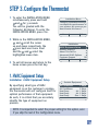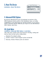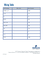
1
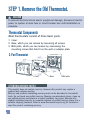
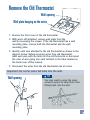
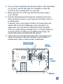
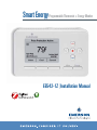
Smart Energy Programmable Thermostat + Energy Monitor
EE542-1Z I Installation Manual
Contents
1
Introduction
2
Getting Started
3
Installing the Thermostat
Quick Guide
3
4
6
9
14
17
19
20 - 22
Back Cover
Step 1: Remove the Old Thermostat
Step 2: Mount the New Thermostat
Step 3: Configure the Thermostat
Step 4: Check Thermostat Operation
Step 5: Pair Device to Home Area Network
Step 6: Verify Wireless Connectivity
Wiring Chart
Wiring Table
Introduction
• About this Guide
This guide describes how to install and configure your new
Smart Energy thermostat.
• System Compatibility
This product replaces most thermostats, including those
that work with:
• Standard Heat and Cool Systems
• Two-Stage Heat and Two-Stage Cool Systems
• Air Source Heat Pump (with Aux. or Emergency Heat)
• Ground Source Heat Pump (with Aux. or Emergency Heat)
• Air or Ground Source Heat Pump (No Aux. or Emergency Heat)
• Standard Heat Only Systems
• Standard Central Air Conditioning
• Gas or Oil Heat
• Electric Furnace
• Hydronic (Hot Water) Zone Heat – 2 Wire zone valves
CAUTION
Failure to read and follow all instructions carefully before installing or
operating this control could cause personal injury and/or property
damage.
To prevent electrical shock and/or equipment damage, disconnect
electric power to system at main fuse or circuit breaker box until
installation is complete.
Do not use on circuits exceeding specified voltage. Higher voltage will
damage control and could cause shock or fire hazard.
1
Getting Started
Pre-Installation Checklist
Before you begin to install your Smart Energy thermostat:
Read these instructions thoroughly.
Check the package from your thermostat to make sure you have
all of the required items (see below).
Check to ensure you have the required tools (see below).
Required Items
Note: This product requires a
24v AC power supply via the
C terminal for operation.
• Thermostat (1)
• Wall anchors (2)
• Mounting screws (2)
Required Tools
• Flat blade screwdrivers – 1 large and 1 micro tip
• Hand or power drill with 3/16 inch drill bit
• Wire strippers
• Level (optional)
2
O/B
G
W/E
W2
L
Y2
Y1
RC
RH
C
Quick Guide
STEP 1. Remove the old thermostat
• Turn off power at the breaker.
CAUTION
To prevent electrical shock and/or equipment damage, disconnect
electric power to system at main fuse or circuit breaker box until
installation is complete.
• Remove cover from old thermostat to expose wires.
• Document which wires go to which terminals using the table
on the back of this manual.
• Disconnect wires and remove old thermostat, making sure that
thermostat wires do not fall back into wall opening.
STEP 2. Mount the new thermostat
• Feed thermostat wires through thermostat hole.
• Wire new thermostat.
• Turn on power at breaker.
STEP 3. Configure the thermostat
STEP 4. Check thermostat operation
STEP 5. Verify wireless connectivity
The sections that follow provide detailed instructions
for completing these steps.
3
STEP 1. Remove the Old Thermostat.
CAUTION
To prevent electrical shock and/or equipment damage, disconnect electric
power to system at main fuse or circuit breaker box until installation is
complete.
Thermostat Components
Most thermostats consist of three basic parts.
1. Cover
2. Base, which you can remove by loosening all screws
3. Wall plate, which you can remove by unscrewing the
mounting screws that hold it on the wall or adaptor plate
3-Part Thermostat
Cover
Base
Wall plate
ATTENTION: MERCURY NOTICE
This product does not contain mercury. However this product may replace a
product that contains mercury.
Mercury and products containing mercury must not be discarded in household
trash. Do not touch any spilled mercury. Wearing non-absorbent gloves, clean up
any spilled mercury and place in a sealed container. For proper disposal of a
product containing mercury or a sealed container of spilled mercury, place it in a
suitable shipping container. Refer to www.thermostat-recycle.org for location to
send the product containing mercury.
4
Remove the Old Thermostat
Wall opening
Wall plate hanging on the wires
1. Remove the front cover of the old thermostat.
2. With wires still attached, remove wall plate from the
wall by loosening the screws. If the old thermostat has a wall
mounting plate, remove both the thermostat and the wall
mounting plate.
3. Identify each wire attached to the old thermostat as shown in the
diagram below. Before removing wires from old thermostat,
label each wire with the letter on the old thermostat or document
the color of wire going into each terminal in the table located on
the back cover of this manual.
4. Disconnect the wires from the old thermostat one at a time.
Important: Do not let wires fall back into the wall.
TIP
You may want to wrap the wires
around a pencil to keep them from
falling back into the wall.
W
Wall opening
C
5
STEP 2. Mount the New Thermostat
CAUTION
Take care when securing and routing wires so they do not short to
adjacent terminals or rear of thermostat. Personal injury and/or
property damage may occur.
Mount the new thermostat
1. Unpack the thermostat and separate the mounting plate from the
thermostat. Remove the packing material from the thermostat.
Gently pull the thermostat straight off of the base. Hold the back
of the thermostat by the lower corners with one hand, and pull
the wall plate off with the other hand.
NOTE: Forcing or prying on the thermostat will cause damage to the unit.
2. Feed thermostat wires through rectangular hole between the
terminal blocks in the thermostat wall plate.
Feed wires through
this hole from back
O/B
G
W/E
W2
L
C
Y2
Y1
RC
RH
C
Mounting
holes
Wall plate
6
3. Once you have established the desired location of the thermostat,
use a pencil, and the wall plate as a template, to mark the
location of the mounting holes on your wall.
4. Move wall plate out of the way and drill two holes using a
3/16" drill bit.
5. Feed the thermostat wires through the rectangular hole and
fasten wall plate loosely to wall using two mounting screws in
mounting holes.
If desired, place a level against bottom of the wall plate and
adjust until level before tightening screws (leveling is for
appearance only and does not affect thermostat operation).
If you are using existing mounting holes, or if holes drilled are
too large and do not allow you to tighten base snugly, use
plastic wall anchors included with the product.
6. Connect wires to the thermostat wall plate. The image below
shows the location of the wire terminals. Each terminal is
labeled with a letter or letter number combination.
Feed wires through
this hole from back
O/B
G
W/E
W2
L
C
Connect
wires here
Y2
Y1
RC
RH
C
Wire
Terminals
Wall plate
7
Connect wires as follows:
• If necessary, strip insulation about 3/8 inch from the end
of the wire.
• Use the table you previously filled out on the back of the
installation manual (or the wiring chart on page 20) to locate
the correct terminal for each wire connection.
• Bend the wire slightly, insert the wire under the contact plate,
and use a small flat head screwdriver to secure the wire
into place.
7. Push excess wire into wall and plug hole with a fire resistant
material (such as fiberglass insulation) to prevent drafts from
affecting thermostat operation.
8 Fasten thermostat to wall plate using the quick connect feature.
Make sure the retention tabs on the wall plate are in line with
the retention slots on the thermostat. Gently press the
thermostat onto the wall plate until you hear a clicking sound.
If the thermostat does not easily click do not press with
excessive force or damage could occur to the product.
9. Turn power back on at the breaker.
8
STEP 3. Configure the Thermostat
1. To enter the INSTALLATION MENU,
simultaneously press and hold
and for 3 seconds.
You will be greeted with the
following disclaimer. To enter the
INSTALLATION MENU, press Yes.
Installation Menu
Changing installation settings
can impact the performance of
your system. Are you sure you
want to enter this menu?
No
Yes
2. While in the INSTALLATION MENU,
and scroll the cursor
up and down respectively, the
goes back one menu level
and the and select the
highlighted menu item.
3. To exit all menus and return to the
Installation
Settings
HVAC Equipment Setup
Network Settings
About This Device
Advanced HVAC Options
Customer Support
Off
Exit
home screen press the Exit key.
1. HVAC Equipment Setup
Installation > HVAC Equipment Setup
By specifying what type of HVAC
equipment is on the customer’s premise,
the thermostat will self configure itself for
optimal performance of that equipment.
As such, it is critical that you accurately
identify the type of equipment on
premise.
Outdoor
Settings
Equipment
Air Conditioner
1 Stage
Air Conditioner
2 Stage
Heat Pump
Air - 1 Stage
Heat Pump
Air - 2 Stage
Heat Pump
Geo - 1 Stage
NOTE: It is important to select the proper setting for this option, even
if you skip the rest of the Configuration menu.
9
If the system is a single or multi-stage conventional
system, your options are:
Outdoor Options:
Indoor Options:
• Air Conditioner: 1 Stage (default)
• Air Conditioner: 2 Stage
• Air Handler: No Heat
• Air Handler: Electric Heat – 1 Stage
• Air Source Heat Pump: 1 Stage
• Air Handler: Electric Heat – 2 Stage
• Air Source Heat Pump: 2 Stage
• Furnace Gas / Oil – 1 Stage (default)
• Geothermal Heat Pump: 1 Stage
• Geothermal Heat Pump: 2 Stage
• Furnace Gas / Oil – 2 Stage
• Boiler: 1 Stage
• None
• Boiler: 2 Stage
NOTE: The presence of a wire in the W2 terminal is a good indication
that the user has two-stage equipment located inside the house
(furnace, air handler, or boiler). The presence of a wire in the Y2
terminal is a good indication that the homeowner has two-stage
equipment located outside the house (air conditioner or heat pump).
2. Network Settings
Installation > Network Settings > Installation Information
This menu item provides you with the MAC ID and ZigBee Installation
Code that will be requested from you when you pair this device to a
ZigBee network.
Installation > Network Settings > Network Connection
This menu option enables you to
send a join request to the ZigBee
network. For more information on
this process, see step 5 (page 18).
10
Installation
Settings
Information
Installation Code
XXXX-XXXX
MAC Address
XXXX-XXXX-XXXX-XXXX
3. About This Device
Installation > About This Device
AboutSettings
This Device
Model #
EE542-1Z
Thermostat Firmware
V.1.0
Radio Firmware
V.1.0
Boot Loader Firmware
V.1.0
4. Advanced HVAC Options
By properly identifying the type of equipment on premise in the
HVAC Equipment Setup portion of the installation menu, no further
modifications to the thermostat are required. However, if you want to
further customize specific attributes you may do so via the Advanced
HVAC Options menu item.
4A. Cycle Rates
Installation > Advanced HVAC Options > Cycle Rates
This menu item controls cycle rate choices for heating, cooling and
back-up heat (on heat pump configuration).
• Standard: The default setting.
• Comfort: Choose if more frequent cycles are desired.
• Economy: Choose if fewer cycles are desired.
11
4B. Compressor Lockout
Installation > Advanced HVAC Options > Compressor Lockout
This feature is intended to help protect the compressor from short
cycling. Some newer compressors already have a time delay built in
and do not require this feature. Your compressor manufacturer can
verify if the lockout feature is already present in their system.
Options for this menu item include:
• OFF: (Default) No compressor wait time; assumes lockout feature is
already present.
• ON: Waits five minutes before turning on the compressor after a power loss or
during cooling/heating cycles. Protects the compressor from short cycling.
4C. Comfort Alert Active Protection
Installation > Advanced HVAC Options > Comfort Alert
The thermostat is compatible with air conditioners and heat pumps
that feature Copeland Comfort Alert™ protocol. When the thermostat is
connected to comfort alert enabled equipment and active protection
is selected, the thermostat will turn off the compressor if a condition
exists that may potentially damage the system.
If the thermostat is connected to Comfort Alert™ enabled HVAC
equipment, it is recommended that you turn on the Comfort Alert
feature in the thermostat. When the feature is turned on and a
condition exists that may potentially damage your air conditioner or
heat pump, the thermostat will automatically shut off the compressor
and display “Call For Service” on the home screen. When you see this
message, it is recommended that you call a qualified contractor to
schedule a repair appointment.
12
4D. O/B Configuration
Installation > Advanced HVAC Options > O/B Configuration
This configures whether the O/B terminal for the heat pump reversing
valve will be energized during cool (O) or heat (B) mode.
4E. Fast Second Stage (for homes with multi-stage systems)
Installation > Advanced HVAC Options > Fast Second Stage
If the user has multi-stage equipment and would like to have the
ability to rapidly heat or cool on command, then set this feature to
the ON position by pressing the ENTER key. Once in this mode, the
thermostat will instantly turn on all available stages when the set
point is manually changed 3 degrees or more from the current room
temperature.
4F. Smart Fuel Logic
(for homes with a heat pump AND gas furnace)
Installation > Advanced HVAC Options > Smart Fuel Logic
The thermostat has the capability to control dual-fuel systems without
an outdoor temperature sensor. The thermostat can determine when
the heat pump is no longer efficient and can perform system
changeover to the gas furnace. In the Smart Fuel Logic menu, choose:
• Standard: The default setting
• Comfort: Brings on gas furnace sooner at higher outdoor
ambient temperatures
• Economy: Brings on gas furnace at lower outdoor
ambient temperatures
13
STEP 4. Check Thermostat Operation
CAUTION
To prevent compressor and/or property damage, DO NOT operate the cooling
system if the outdoor temperature is below 55° F.
Once you have installed your new thermostat, you need to
check that the fan, cooling system, and heating system are all
operating properly.
If you are still in the INSTALLATION MENU, press the Exit key
to exit to the home screen.
If your system does not have a G terminal connection,
proceed to Heating System.
Check fan operation
Menu > Settings > Fan
1. Press the MENU button and select FAN ON in the thermostat
display. The blower should begin to operate. Place your hand by
a vent to confirm blower is running.
2. Select FAN AUTO to return to standard setting. The blower will
only cycle with call for cool or heat.
Check the cooling system
1. Press the Heating / Cooling Mode key one or more times to
select COOL.
2. Press the
to adjust thermostat setting 1° below room
temperature. The blower should come on immediately on
high speed, followed by cold air circulation.
14
NOTE: If compressor lockout is set to ON, the thermostat will not call for cool
until after the 5 minute safety time period and will display the message A/C
return < 5 min. After the 5 minutes expire the thermostat will call for cool.
3. If the system is a multi-stage cooling system, adjust the
temperature setting to at least 3° below room temperature.
The second stage cooling should begin to operate.
4. Press the
to adjust the temperature setting above room
temperature. The cooling system should stop operating.
Check the heating system
1. Press Heating / Cooling Mode key one or more times to select
HEAT mode. If the auxiliary heating system has a standing pilot,
be sure to light it.
2. Press the
to adjust thermostat setting to 1° above room
temperature. The heating system should begin to operate.
NOTE: If the system is configured as a heat pump and compressor lockout is
set to ON, the thermostat will not call for heat until after the 5 minute safety
time period. After the 5 minutes expire the thermostat will call for heat.
3. If the system is a multi-stage heating system, adjust the
temperature setting to at least 3° above room temperature. If the
system is configured for a multi-stage furnace (non-heat pump),
the second stage of the heating should begin to operate. Within a
very short period, the Back Up heat should begin to run and Back
Up Heat will be displayed.
4. Press the
to adjust the thermostat below room temperature.
The heating system should stop operating.
15
Check the back-up heating system
(heat pump systems only):
The Back Up Heat bypasses the heat pump to use the heat source
wired to E & W2 terminals of the thermostat. Back Up is typically
used when compressor operation is not desired, the user prefers to
utilize the back-up heat only, or the compressor is not able to satisfy
the demand for heat to the users desire.
1. Press Heating / Cooling Mode key one or more times to select
Back Up Heat mode. If the auxiliary heating system has a
standing pilot, be sure to light it.
2. Press the
to adjust thermostat setting to 1° above room
temperature. The AUX heating system should begin to operate.
Back Up should display.
3. If the system is a multi-stage Back Up heating system, adjust the
temperature setting to at least 3° above room temperature to turn
on all stages.
4. Press the
to adjust the thermostat below room temperature.
The heating system should stop operating.
16
STEP 5. Pair Device to a Home Area Network
Installation > Network Settings > Installation Information
To pair this device to a network coordinator
(such as a smart meter or IP gateway),
follow these steps:
STEP 1
STEP 2
From the NETWORK SETTINGS screen,
highlight INSTALLATION INFORMATION
and press .
During the pairing process defined by
your utility or service provider, you will
be asked to provide the thermostat’s
installation code and MAC ID numbers
displayed here:
Network
Settings
Settings
Installation Information
Network:
Not Connected
Installation
Settings
Information
Installation Code
XXXX-XXXX
MAC Address
XXXX-XXXX-XXXX-XXXX
17
STEP 3
STEP 4
Once you have provided the two
numbers above you will be asked to
send a “Join” request from the
thermostat. To do so go to the NETWORK
CONNECTION screen.
Press the CONNECT key.
Network Settings
Installation Information
Network:
Not Connected
Network Connection
Status:
Not Connected
Connect
STEP 5
You may have to wait up to 3 minutes
for the pairing process to be completed.
During that time you will see the
following content on the display:
Attempting to Join Network
Cancel
STEP 6
Once you have successfully joined the
network you will see the following
screen.
Connection
Successful
18
STEP 6. Verify Wireless Connectivity
STEP 1
The following screen in the NETWORK
SETTINGS area of the installation menu
will serve as further confirmation of
network connectivity:
Network
Settings
Connection
Status:
Connected
Leave
STEP 2
On the home screen, a wireless icon will
also confirm that the unit is in fact
connected to a network coordinator.
1:54 PM - Mar. 12
Base Rate
$0.08 kWh
Inbox
STEP 3
If a connection is not made, the words
“NO CONNECTION” will appear.
75
Hold At
F
77
Hold Until
5:30PM – Mon
End
Hold
Heat
1:54 PM - Mar. 12
NO
CONNECTION
Inbox
75
Heat
Hold At
F
77
Hold Until
5:30PM – Mon
End
Hold
NOTE: Immediately upon joining the network, “Syncing Time” may appear
on the home screen for up to 10 minutes while the product obtains time
from the meter or gateway device.
19
Wiring Chart
NOTE: No thermostat
installation uses all of the wires
shown below. In most cases,
between 5 and 6 terminals are
wired. The remaining terminals
will not be used.
O/B
G
W/E
W2
L
O/B
Y2
Y1
RC
RH
C
Y2
G
Y1
W/E
RC
W2
RH
L
C
For all systems, the following terminals are wired according to
whether you have a single or dual transformer system as shown:
RH
Single
Transformer
System
Dual
Transformer
System
RC
24 VAC Hot
Jumper should remain installed
24 VAC – Heat
* REMOVE
PROVIDED JUMPER
C
L
G
24 VAC System/Comfort Blower/
Fan
Common Alert Diagnostics
24 VAC – Cool
24 VAC System/Comfort Blower/
* REMOVE
Common Alert Diagnostics
Fan
PROVIDED JUMPER
WARNING
* FAILURE TO REMOVE PROVIDED JUMPER ON DUAL TRANSFORMER
INSTALLATIONS COULD CAUSE SEVERE DAMAGE TO HVAC SYSTEMS.
NOTE: This product requires 24V power supply via the C terminal to operate.
20
The following terminals on the thermostat Mounting Plate are wired
according to the type of HVAC system connected to and the
thermostat is configured as:
Y1
Y2
W/E
W2
O/B
Conventional
HVAC
Cool Mode
Stage 1
Cool Mode
Stage 2
Heat Mode
Stage 1
Heat Mode
Stage 2
–
Heat Pump
Compressor
Contactor
Compressor
Stage 2
AUX Heat
Stage 1
AUX Heat
Stage 2
Reversing
Valve
NOTE: This product requires 24V power supply via the C terminal to operate.
21
Wiring Table
Old Terminal
Wire Color
New Terminal
W, W1, 4, E
W/E
Y, Y1
Y1
G
G
RC, R
RC
RH, 5, R5
RH
W2, W-U
W2
Y2
Y2
C
C
L, F
L
O, B
O/B
37-7301C
2013 Emerson, Emerson Climate Technologies are trademarks of
Emerson Electric Co. or one of its affiliated companies. ©2013 Emerson Electric Co.
All rights reserved.