1
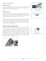
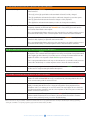
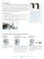
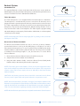
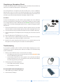
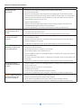
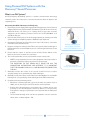
Tools for Schools
Harmony® Sound Processor
Product Guide
For Educators, Therapists, and Families
Harmony Sound Processor
The Harmony Sound Processor is uniquely designed to provide the latest in sound-processing
technology with user functionality. Harmony features CD-quality processing as well as
Autosound™ (a wide sound window), which allows children to hear in noisy classrooms and
experience language naturally. Additionally, Harmony offers a multifunctional LED,
improved battery life, and it is water resistant.
This guide provides information
on the features, accessories,
and use of the Harmony Sound
Processor. Should you need
support beyond this document,
please contact us at 877.829 .0026,
Monday through Friday, 5 a.m. to
5 p.m. PST, and ask to speak with
an audiologist, or you can visit
our website at www.BionicEar.com.
Built-in
Microphone
Built-in LED Status Light
Volume Control
Built-in TeleCoil
Program Switch
Processor Module
Headpiece Cable
Connector
T-Mic® Microphone
Earhook
PowerCel™
Rechargeable Battery
Accent Color
Cover
Headpiece and Cable
with Color Cover
Quick-Start Guide and System Checks:
Step 1: Slide the fully charged PowerCel onto the Processor Module. This will turn on the
Harmony Sound Processor. Check to ensure that the PowerCel is in a fully aligned
position with the Processor Module and that the PowerCel is charged by verifying
that the LED sequence displays three to four quick orange blinks.
Step 2: Position the Accent Color Cover over the Harmony Processor and snap into place.
Step 3: Make sure that the Headpiece Cable is plugged into the Processor Module. Check
that the Cable is not twisted or frayed.
Step 4: Align and gently snap into place the selected Earhook. Check to verify that the
Earhook is properly positioned. To remove the Earhook, turn to the right or left
until the Earhook releases from the post.
Step 5: Verify that the Program Selector and Volume Control are in the desired position.
Step 6: Ensure that the Processor is in a comfortable position behind the ear.
Step 7: Ensure that the Headpiece is positioned over the internal implant (you will feel
the magnetic attraction).
Step 8: Perform a behavioral listening check, using the Ling Six sounds or another
listening activity.
TOOLS for Schools by Advanced Bionics
2
Harmony® Sound Processor Product Guide
Harmony Features
Program Switch
The Harmony Sound Processor can store up to three (3) programs (P1, P2, P3).
The Program Switch has three positions to represent each program. P1 is at the
bottom, P2 is in the middle, and P3 is at the top.
P1 P2 P3
Harmony Program Switch
Volume Control
Volume Control allows the loudness level to be adjusted. Turning the control in a
clockwise direction increases the loudness; turning the control counterclockwise
decreases the loudness. The volume position is indicated by the white dot on the
dial. The Volume Control is typically set at the 12 o’clock position.
Decrease
Volume
Increase
Volume
Volume Control
The audiologist has the ability to restrict or limit the Volume Control dial. Although
the dial will continue to work, a restricted range will limit the actual decrease or
increase to sound as the dial is moved. Programming the Volume Control in this
manner prevents accidental changes in loudness (either too soft or too loud), which
could compromise the child’s hearing
Headpiece with Integrated Cable
The Headpiece contains the transmitter for sending sound information to the implant.
There is no Microphone in the Headpiece. The Cable provides a relay for the transfer
of signals between the Headpiece and the Harmony Sound Processor. The
Headpiece and Cable are one unit and should not be separated. To connect the
Headpiece to the Harmony Processor, simply align the raised area on the end of
the Cable with the groove on the Headpiece Cable connection port located
below the Program Switch on the body of the Processor, then slide into place
until secure. To remove the Headpiece from the Harmony Sound Processor, hold
the Cable’s connector and gently pull it away.
Headpiece and Cable
Connecting and Removing the Headpiece
TOOLS for Schools by Advanced Bionics
3
Harmony® Sound Processor Product Guide
The Microphone
The Sound Processor Microphone is located directly behind the base of the Earhook
positioned at the top of the Harmony Processor. Children may also use an integrated
Earhook and Microphone called a T-Mic®. (For more information on the T-Mic, see
the Earhook section of this guide.)
Telecoil
The Harmony Sound Processor contains a built-in Telecoil (T-Coil) option that can be
enabled and downloaded to any of the Processor’s three program locations. Contact
the child’s family or cochlear implant center to determine if this feature is active. In
order for the T-Coil to be effective, the cochlear implant user must have access to a
looped system or a hearing-aid-compatible telephone. This will allow the T-Coil to
receive the electromagnetic field generated by these devices. If the cochlear implant
user is attempting to use the T-Coil with a non-compatible audio device, they may
hear no sound or a low-level humming or buzzing noise. (See Audio Mixing for more
important information on this feature.)
Sound Processor Microphone
Note: An external T-Coil can also be used with the Harmony Sound Processor and
the Direct Connect Earhook.
Harmony Tri-Color Light Emitting Diode (LED)
The Harmony Sound Processor is equipped with a built-in Light Emitting Diode
(LED) Status Indicator. The LED is a diagnostic light that provides parents and
teachers with information regarding the functionality of the Harmony Sound
Processor. The LED is located above the Volume Dial and can be programmed
to provide the following information:
Feature
Color
PowerCel Status
Orange
Microphone Status
Green
Communication Status
Red
TOOLS for Schools by Advanced Bionics
Harmony Sound Processor Equipped
with Built-in Light Emitting Diode
Status Indicator
4
Harmony® Sound Processor Product Guide
The orange LED communicates three (3) features about PowerCel Status
1. PowerCel Charge
The LED will flash ORANGE up to four (4) times to indicate the charge status
of the PowerCel.
• Three (3) to four (4) quick flashes indicate that the PowerCel is fully charged.
• Two (2) quick flashes indicate the PowerCel is sufficiently charged to power the system.
• One (1) quick flash indicates the PowerCel charge is nearly depleted.
• Zero (0) flashes indicate that the battery needs to be changed immediately.
2. C
hange Battery Indicator
When the PowerCel is depleted to the point that it is unable to support stimulation but not
completely depleted, the LED will flash ORANGE twice every three (3) seconds and no
sound will be transmitted to the implant.
This is a programmable feature and may not be activated on your child’s sound processor.
Contact the child’s family or the cochlear implant center to have this feature activated.
3. Low Battery Indicator
When the PowerCel is near depletion, the LED will illuminate ORANGE steadily. Once the
PowerCel is fully depleted, no light will emit from the LED.
This is a programmable feature and may not be activated on your child’s sound processor.
Contact the child’s family or cochlear implant center to have this feature activated.
The Green LED communicates two (2) features about Harmony’s Microphone
1. Mic/System Status Indicator
The LED will flash GREEN in response to loud sounds presented near the Processor
Microphone. This verifies that the Microphone is receiving sound, data is being transmitted
to the implant, and the Harmony Sound Processor is receiving information back from the
implant. The LED is not expected to flash GREEN in quiet environments.
This is a programmable feature and may not be activated on your child’s sound processor.
Contact the child’s family or cochlear implant center to have this feature activated.
2. Mic Test Mode Indicator
When an empty program slot is selected, the LED will illuminate GREEN steadily, indicating
the Processor is ready for testing the built-in Microphone.
The red LED communicates three (3) features about Error Conditions
1. Lock Status Indicator
The term “lock” refers to the successful communication between the Processor and
implant. The LED will flash RED at one (1) second intervals, indicating that the Processor
is not communicating with the internal device.*
2. IntelliLinkTM Indicator
Should a child accidentally attempt to use the wrong Processor, the LED will flash RED
rapidly, indicating that the Processor is trying to lock with the wrong implant and no
stimulation will occur resulting in no sound received. This may happen when a child who
uses bilateral implants mistakenly puts his or her implants on the wrong ears or when two
children switch Sound Processors.
3. Processor Error Indicator
In rare instances, the LED may emit a continuous RED light. This indicates a potential
problem with the Harmony Processor. Remove and reinsert the PowerCel to reset the
Processor. If the problem persists, proceed to Troubleshooting.
*Please note for those using SoundWave 1.4.98 the Lock Status Indicator is a programmable feature and may be disabled by the child’s programming
audiologist. SoundWave 1.6 is pending regulatory approval in the United States by the FDA.
TOOLS for Schools by Advanced Bionics
5
Harmony® Sound Processor Product Guide
Power Options
The PowerCel Battery is used to power the Harmony Sound Processor. There are two
types of PowerCel Batteries that can be used with the Harmony Sound Processor: the
PowerCel™ Slim or PowerCel™ Plus. The PowerCel Plus is larger than the PowerCel
Slim and provides increased operating time before a battery change is needed.
Individual operating times vary, depending on certain characteristics of the implant
user’s program settings, but, as a guideline, the PowerCel Slim and the PowerCel
Plus should provide a full day of use. PowerCels can be fully recharged in 4–5 hours
and do not need to be fully depleted before recharging.
How to Replace the PowerCel
1. Locate the tracks on the underside of the Processor and the top of the PowerCel.
The Accent Color Cap will need to be removed.
2. Position the PowerCel so that the contact is toward the back of the Processor.
3. Guide the PowerCel onto the tracks on the Processor.
4. Slide the PowerCel onto the Processor until it stops and is aligned with the Processor.
Do not force the PowerCel onto the Processor.
PowerCel Slim and PowerCel Plus
NOTE: The Harmony Sound
Processor is turned on and off
by connecting or removing the
PowerCel. When not in use, the
parent or child should remove
the PowerCel, otherwise the
Harmony Sound Processor
remains on, and the PowerCel
continues to drain.
Connecting the PowerCel
Flexible wearing options for the Harmony Sound Processor
(All-on-the-Ear)
Harmony BTE
(Some-on-the-Ear)
Harmony BTE with PowerCel™ Adapter*
(Nothing-on-the-Ear)
Kinder Clip™*
This comfortable behind-the-ear
option features a sleek and
convenient design.
Ideal for small ears and active lifestyles! You
can wear the battery completely off the ear.
This bilateral-ready option can power two
Harmony BTEs from a single battery for
added comfort and convenience.
The Kinder Clip allows Harmony to grow
with your child, enabling the processor to
be worn completely off the ear and on the
collar or shirt instead. Customizable for
your preferred battery.
*The Some-on-the-Ear power option configuration of the Harmony
Processor is not approved for use in the United States.
*Under development.
TOOLS for Schools by Advanced Bionics
6
Harmony® Sound Processor Product Guide
Earhook Options
Standard Earhook
The standard Earhook is a basic hook that holds the Processor on the child’s ear.
With this Earhook in place, the built-in Microphone, located at the top of the Processor,
is active. The Earhook comes in Standard and Small sizes.
Standard and Small Earhook
T-Mic® Microphone
The T-Mic Microphone is an integrated Earhook and Microphone combination.
The Microphone is omnidirectional (accesses sound from all directions) and is
designed to fit in the open-bowl portion of the ear, near the entrance to the ear canal.
The T-Mic is appropriate for everyday use and, due to the natural positioning of the
Microphone, may provide improved benefit in difficult listening situations such as
noisy environments or while on the telephone. The T-Mic requires a program setting
with Audio Mixing to work properly. Check with the child’s family or cochlear implant
center for processor settings.
T-Mic Microphone
(Standard and Small)
Note: Avoid bending the T-Mic in sharp angles (90Ω or greater), as this can shorten
the lifespan of the T-Mic.
Direct Connect™ Earhook and Cable
The Direct Connect Earhook allows the user to connect to a variety of batterypowered audio devices—such as an iPod, MP3 player, or CD player—as well as
other assistive-listening devices. To connect, a Direct Connect Cable and an Audio
Interface Cable are required along with the Earhook. The Direct Connect Cable
is available in the following lengths: 11, 24, and 36 inches. To use the Direct
Connect Earhook:
1. Place the Direct Connect Earhook onto the Sound Processor post.
Direct Connect Earhook
(Standard and Small)
2. Snap the Direct Connect Cable onto the Earhook.
3.Using the Audio Interface Cable, connect the Direct Connect Cable (Audio
Interface Jack) to the listening device audio output port.
Note: The auxiliary jack on both Cables is 3.5 mm in size and is designed for stereo
input. A silver Adapter is provided with the Direct Connect System. This is required to
connect a device with a mono output, such as an AM radio, to the Direct Connect
Cable or Interface.
CAUTION: Only battery-powered devices should be connected into the Direct
Connect, unless a patch cable with special electronic components is used.
Direct Connect Cable/Adapter
Audio Interface Cable
Note: We recommend that an earmold, or Snuggie™, be utilized in addition to the
Earhook to securely fasten the Sound Processor to the child’s ear. Earmolds are custom
made for the child and are available for all of the Earhooks we provide, including the
T-Mic. For more information regarding earmolds, contact the child’s audiologist.
Note: All of the Earhook options listed are compatible with the Auria Sound Processor.
Snuggie™
TOOLS for Schools by Advanced Bionics
7
Harmony® Sound Processor Product Guide
iConnect™ Adapter
The iConnect Adapter allows a wireless connection to a miniature personal FM
receiver. The iConnect does not come standard in the child’s Harmony Processor
Kit but can be purchased separately through Advanced Bionics.
Attaching/Removing an Earhook
To Attach: Align the Earhook flush with the Harmony Sound Processor and push to
snap in place. Gently pull back to confirm that the Earhook is secure.
iConnect Adapter
(Standard and Small)
o Remove: Turn the Earhook slightly more than ¼ turn in either direction until it
T
releases.
Removing an Earhook
Audio-Mixing
Audio-Mixing refers to the amplification ratio between the Processor Microphone
and an auxiliary input device. Audio-Mixing allows the child’s Processor Microphone
to remain on when connected to an auxiliary input, such as an active T-Coil, FM
System, or auxiliary device. This is important because it enables the child to hear his
own voice and sounds around him in addition to the input from the auxiliary device.
The Audio-Mixing is set for each program on the Sound Processor by the audiologist
during programming. The default Audio-Mixing recommendation is 50/50. For a
description of the Audio-Mixing options, refer to the table below.
Audio-Mixing Options Processor Microphone Auxiliary Input (i.e. FM System)
Mic Only
On
Off
50/50 - Mic/Aux*
On
On
30/70 - Mic/Aux**
On (-10dB)
On
Aux Only (Atten.)
Off
On (-20dB)
Aux Only
Off
On
*For classroom use and the default programming setting
**For noisy environments where greater input is needed from the FM (i.e., theatre,
church, noisy restaurant, etc.)
TOOLS for Schools by Advanced Bionics
8
Harmony® Sound Processor Product Guide
Accessories for the Harmony
Auxiliary Microphone
• The Auxiliary Microphone, also called a lapel microphone, is an additional
microphone that can be used in a number of ways. The Auxiliary Microphone
plugs into the auxiliary input jack of the Direct Connect Cable and is for use:
• During therapy, or in noisy environments, as it improves the signal-to-noise
(S/N) ratio.
• As a way to troubleshoot the child’s Processor. In the event that the child
stops responding to sound with what looks like a functional Processor,
plug in the Auxiliary Microphone and perform a simple listening check
with the child.
•As a secondary Microphone in the event that the child’s Processor Microphone is not working.
Auxiliary Microphone
The Auxiliary Microphone can be purchased by contacting Advanced Bionics.
Carrying Case
The Carrying Case is designed to hold all of the basic Harmony Sound Processor
components and serve as a Dri-Aid Kit. It is recommended that Harmony Sound
Processor components be stored in the Carrying Case when not in use or in
situations where the Harmony Processor was exposed to excessive moisture.
Carrying Case
Note: The Drying Agent within the Carrying Case should be periodically reactivated.
Accent Color Covers and Caps
A unique variety of snap-on Color Covers and Caps are available. These are easily
snapped on or off of the Harmony Sound Processor or Headpiece and are sized to
fit the Processor Module and battery, when attached.
Accent Color Covers and Caps
TOOLS for Schools by Advanced Bionics
9
Harmony® Sound Processor Product Guide
Harmony Processor Troubleshooting
Determining Device Function
Use the Harmony Processor’s built-in Tri-Color LED to determine device function.
For details on how to use the LED to determine device function, see the Tri-Color
Color LED section below:
LED Sequence
1. When the PowerCel is first attached to the Harmony Processor, the LED will
indicate the PowerCel charge status by flashing ORANGE.
• Three (3) to four (4) quick ORANGE flashes indicate that the PowerCel is
fully charged.
• Two (2) quick ORANGE flashes indicate that the PowerCel is sufficiently
charged to power the system.
• One (1) quick ORANGE flash indicates that the PowerCel charge is nearly
depleted.
• Zero (0) ORANGE flashes indicate that the battery needs to be changed
immediately.
2. Following the PowerCel charge status sequence the LED will indicate Lock Status by flashing RED.
• The LED will flash RED approximately once per second until lock is achieved.
• Once the Headpiece is properly positioned on the student’s head, and information is transmitting to the implant, the RED flashing will stop.
3. When the PowerCel and Lock Sequences are complete, the LED will indicate
Microphone and system status by flashing GREEN.
• The LED will flash GREEN in response to loud sounds presented near the
Processor Microphone. This verifies that the Microphone is receiving sound,
data is being transmitted to the implant, and the Harmony Processor is receiving information back from the implant.
• The LED is not expected to flash GREEN in quiet environments.
Note: The Low Battery Indicator,
Change Battery Indicator, Lock
Status Indicator (SoundWave
1.4.98 and subsequent builds),
and Mic/System status Indicator
are programmable features and
may not be activated on the
child’s processor. These programmable features are often helpful for
educators working with children
who use the Harmony Processor.
You can contact the child’s family or
cochlear implant center to request
that these features be activated.
Note: The System Sensor is
NOT compatible with the Harmony
Processor and may indicate that
the Harmony Processor is
functioning appropriately (solid
green light) when Harmony is
not transmitting a signal to the
internal device. Use Harmony’s
built-in LED to determine the
status of the Harmony Sound
Processor.
System Sensor
NOTE: The FireFly (system status
Earhook for the Auria BTE) is NOT
compatible with the Harmony
Processor. Use the Harmony’s
built-in LED to obtain information
about the Harmony Processor’s
status.
TOOLS for Schools by Advanced Bionics
10
Harmony® Sound Processor Product Guide
Completing a Microphone Check
To test the internal Microphone of Harmony, you will need a Direct Connect Earhook,
Direct Connect Cable and Microphone Test Earphones.
You should perform a microphone test when the Processor is new, to establish a
baseline from which to monitor the internal Microphone for any sound-quality
issues. The microphone test only assesses the internal Microphone of the Processor
and will not provide information about the Headpiece Cable or T-Mic.
Procedures
To assess the Microphone, you will need an empty program slot on the Harmony
Processor. Speak with the child’s family or audiologist to determine which program
slot is empty. Harmony’s built-in LED will illuminate GREEN steadily when an empty
program slot is selected, indicating that the Processor is ready for testing the built-in
Microphone.
1. Remove the Harmony Processor from the child. You will not hear any sound and
will not be able to monitor the Microphone if the child is wearing the Processor.
2. Connect the Direct Connect Earhook and Direct Connect™ Cable to Harmony.
3. Insert the Microphone Test Earphones into the input jack on the Direct Connect
Cable.
Harmony with Direct Connect™ Earhook
and Microphone Test Earphones
4. Place the Microphone Test Earphones on your ears.
5. Turn on the Processor (attach battery) and select the microphone test position
(empty program slot), using the program control switch.
6. Monitor the sound output from the Processor as you speak clearly into the
Microphone. Sounds and speech should be clear but amplified.
Troubleshooting
If you suspect a problem with the child’s cochlear implant equipment, we recommend that you verify the following items before proceeding to the Troubleshooting
chart located below:
1. Make sure the child’s Processor is set to his/her user settings.
• Is the battery in place and were there three (3) to four (4) Orange blinks
from the LED following placement?
• Is the Volume Control in the correct position? As a reminder, the Volume
Control should be in the 12 o’ clock position unless otherwise instructed by
the child’s programming audiologist.
2. Visually inspect the child’s equipment.
• Is the Cable twisted, frayed or broken?
• Is the Headpiece cracked?
HiRes 90K® Auria Headpiece and Cable
Recommended Troubleshooting Equipment:
1. HiRes 90K® Auria® Headpiece and Cable
2. Auria PowerCel® Charger
PowerCel® Battery Charger
TOOLS for Schools by Advanced Bionics
11
Harmony® Sound Processor Product Guide
Harmony Troubleshooting Situations:
Problem
Action
Child cannot hear
(No Sound)
1.
2.
3.
4.
Red LED flashes rapidly
and the child reports no
sound.
1. This is the IntellilLnk™ feature working and indicates that the Sound Processor is trying to
lock with the wrong internal device.
2. Check Sound Processors to ensure you have the appropriate Processor in place.
Red LED continuously
blinks at one-second
intervals.
1.
2.
3.
4.
5.
Green LED does not
illuminate to loud speech
close to Microphone.
1.
2.
3.
4.
5.
Child reports hearing
sounds that are distorted
or static.
1. Ensure Headpiece Cable is not damaged (kinked or frayed) and is properly inserted into
the Sound Processor.
2. Ensure the Volume is at the 12 o’clock position.
3. Try alternative program.
4. Listen for static using the Microphone Test procedures.
5. Contact the programming center and/or the child’s family for further troubleshooting.
Orange LED on Harmony
does not blink when the
Processor is turned on.
1.
2.
3.
4.
Check your connections, including PowerCel, Earhook and Cables.
Check the Volume Dial.
Make sure the PowerCel is fully charged and inserted properly. Try another PowerCel.
Check the Microphone/System status, using the LED. To do this speak close to the child’s
Harmony Processor while it is properly positioned on the child and look for the LED to
flash Green in response to your voice.
5. Replace Cable/Headpiece.
6. Perform a test of the built-in Microphone, using an empty program slot. Refer to the
Completing a Microphone Check section listed above.
7. Contact programming center and/or child’s family for further troubleshooting.
Make sure the Headpiece is on the child’s head and positioned over the implant site.
Check Headpiece/Cable.
Determine if the Microphone is working by following the Microphone Test Procedures.
Replace Headpiece, if necessary.
Contact the programming center and/or child’s family for further troubleshooting.
Confirm that this option is enabled.
Recheck the PowerCel status.
Check Volume Control to ensure it is set correctly.
Try another program on the child’s Processor.
Ensure Headpiece Cable is not damaged (kinked or frayed) and is properly inserted into
the Sound Processor.
6. Check the Processor Microphone to determine functionality using the Microphone Test
Procedures.
7. Contact the programming center and/or the child’s parent for further troubleshooting.
Check your connections between the PowerCel and Processor.
Replace your PowerCel with one that is fully charged.
Clean PowerCel and Harmony Processor contacts using a hearing-aid brush.
Contact the programming center and/or the child’s family for further troubleshooting.
TOOLS for Schools by Advanced Bionics
12
Harmony® Sound Processor Product Guide
Using Personal FM Systems with the
Harmony® Sound Processor
What is an FM System?
An FM (Frequency Modulated) system is a wireless communication technology
commonly used in the classroom to overcome the adverse effects of distance and
competing noise.
Connecting the Child’s Harmony to an FM System:
1. Ensure that you have obtained the appropriate FM equipment, such as iConnect
Adapter, FM Receiver, FM Transmitter and Batteries (size 10 for the iConnect).
Advanced Bionics can assist you in verifying that you have the necessary
equipment via the Auditory Customer Service line at 877.829.0026 or at
www.BionicEar.com.
2. Ensure that the FM System is functioning appropriately by listening to the FM
System through an amplified speaker or Walkman-style earphones.
3. Keeping the FM System and Sound Processor in the “off” position, connect the
Sound Processor and FM receiver.
4. Program or adjust the settings of the FM receiver per the child’s audiologist or
FM manufacturer’s recommendations prior to connecting the Harmony Sound
Processor.
Harmony Sound Processor
with the iConnect™ Earhook
and the Phonak MLxS Receiver
5. Ensure that the volume on the FM receiver and the Volume Wheel on the
Harmony Processor are both set to minimum.
6. Turn on the transmitter, receiver, and Sound Processor in that order.
• Note: It is important that you turn on the equipment in the proper order to
prevent the child from hearing any adverse sound percepts.
THE EXCEPTION TO THIS WOULD BE IF USING THE MLxi THE
CONNECTION INSTRUCTIONS ARE DIFFERENT. IT IS IMPORTANT
THAT THE HARMONY AND iConnect ARE ON PRIOR TO CONNECTING
THE MLxi.
Campus S Transmitter
courtesy of Phonak Corporation.
7. Gradually increase the volume on the child’s Sound Processor to his/her
everyday settings or as specified by the child’s audiologist.
8. Gradually increase the volume on the FM receiver (if available) to a comfortable
listening level or as specified by child’s audiologist or the FM manufacturer.
9. Complete a functional listening check:
• Administer a listening task that you know the child can perform close to
100%, such as, the Ling Six Sound Test and/or common phrases.
• Perform these listening tasks in an auditory-only condition and in close
proximity to the child. Repeat the task at a distance of several meters,
noting that no changes in performance are observed with the FM System
in quiet.
• The functional listening check can also be repeated in noise to assess the
effects of the cochlear implant + FM.
TOOLS for Schools by Advanced Bionics
13
Harmony® Sound Processor Product Guide
Tips to Reduce Interference:
1. Ensure that the transmission range is not exceeded. The broadcast range
between FM transmitters and receivers may begin to break up at distances
greater than 40 feet indoors and 120 feet outdoors.
2.Observe areas in the classroom, or other environments, that can cause “dead
spots” in transmission. Complete a listening check with the FM System in the
classroom to listen for any problem areas and avoid seating the child in these
problem areas.
Troubleshooting the FM System and Cochlear Implant
Keep in mind you are working with two separate systems, an FM System and a
cochlear implant Sound Processor. The best way to complete troubleshooting is to
begin by separating the two systems and troubleshoot them separately.
Troubleshooting the FM System:
1.Disconnect the FM System from the child’s Sound Processor
2.Verify the FM System is working by listening to the FM System. To do this, plug
the FM receiver into a small speaker (RadioShack) or a Headset FM Checker
and verify the signal is being received and is clear.
3.If the FM System is not working, complete troubleshooting for the FM System as
recommended by the FM manufacturer. Ask the following questions:
• Are the FM transmitter and receiver on the same channel?
• Are the cables on the FM transmitter or receiver frayed or kinked?
• Has the transmitting distance been exceeded?
•Do the batteries for the FM transmitter and/or receiver need to be
replaced?
•Is the microphone on the transmitter working?
• Are the FM settings set appropriately?
Troubleshooting the Sound Processor:
1. Can the child hear clearly with the cochlear implant alone?
2.If the child cannot hear with the cochlear implant alone, complete troubleshooting for the Sound Processor as directed by the Harmony Troubleshooting
Situations listed previously in this document.
TOOLS for Schools by Advanced Bionics
14
Harmony® Sound Processor Product Guide
FM Troubleshooting Situations:
Problem
Action
Child cannot hear
when the FM System
is connected
1. Verify that the Harmony Sound Processor is on and at user settings.
2. Verify that the FM System is working, check battery and settings.
3. Verify that your connections are secure.
4. If using the Direct Connect option, verify that you are using the proper FM Adapter Cable.
5. Verify that the Audio-Mixing ratio has been set for FM use (50/50 is recommended for
classroom use).
6. Replace the Direct Connect Cable(s), if this is the connection option being used.
7. If using iConnect, verify that a charged battery is in use.
8. Replace the iConnect.
9. If problem cannot be determined, contact Advanced Bionics for support.
Child reports noise,
static, or distortion with
the FM System
1. Verify that you are using the proper FM Adapter Cable for the FM System and Harmony
Sound Processor if using the Direct Connect feature.
2. Reduce the volume or gain on the FM receiver (if available).
3. Ensure that the transmission range is not exceeded—the broadcast range between FM
transmitters and receivers may begin to break up at distances of 40 feet indoors; 120 feet
outdoors.
4. Ensure that there are no “dead spots” in the classroom.
5. Ensure that the transmitter is worn properly.
6. Try a different FM channel.
7. If problem cannot be determined, contact Advanced Bionics for support.
Green LED on the
Harmony flashes
constantly (if enabled)
1. Reduce the volume and/or gain on the FM receiver.
Listening responses are
poorer with the FM System
and Harmony than with
Harmony alone
1. Verify that Harmony is set to the appropriate program.
2. Verify that Harmony volume is set to the user settings.
2. Reduce the volume on the Harmony Processor.
3. Verify that the Audio-Mixing ratio has been set for FM use (50/50 is recommended for
classroom use).
4. Increase the gain on the FM receiver (this may need to be completed by the audiologist
as there is special software to adjust the parameters of the FM receiver).
5. Try a 30/70 mixing ratio. You may need to consult with the child’s programming audiologist or parents regarding program settings.
6. If problem cannot be determined, contact Advanced Bionics for support.
Child cannot hear his/her
own voice or other’s voices
in the environment
1. Verify the Audio-Mixing setting (should be set to either a 50/50 or 30/70 mixing ratio).
2. Verify the Processor and FM are at user settings.
3. Verify that the child isn’t experiencing any other complaints.
TOOLS for Schools by Advanced Bionics
15
Harmony® Sound Processor Product Guide
FM Manufacturer Resource Information
Phonak Inc, US
Phone: 800.679.4871 • 630.821.5000
[email protected]
www.phonak-us.com
Advanced Bionics®
Phone: 877.829.0026
TTY: 800.678.3575
Monday – Friday 5 a.m. to 5 p.m. PST
[email protected]
www.BionicEar.com
TOOLS for Schools by Advanced Bionics
16
Harmony® Sound Processor Product Guide
Headquarters
Advanced Bionics, LLC
12740 San Fernando Road
Sylmar, CA 91342 USA
877.829.0026 in USA and Canada
800.678.3575 TTY
661.362.1400
661.362.1500 Fax
[email protected]
Europe
Advanced Bionics SARL
76 rue de Battenheim
68170 Rixheim, France
+33.3.89.65.98.00
+33.3.89.65.50.05 Fax
[email protected]
Asia-Pacific
Advanced Bionics Asia-Pacific Limited
Suite 4203, 42/F, Tower One
Lippo Centre, 89 Queensway
Hong Kong
852.2526.7668
852.2526.7628 Fax
[email protected]
Latin America
Advanced Bionics
28515 Westinghouse Place
Valencia, CA 91355 USA
661.362.1840
661.362.4604 Fax
[email protected]
www.BionicEar.com/TFS
Tools for Schools is a free program designed by Advanced Bionics to help children with cochlear implants
succeed in the classroom. The program provides education, support, and tools to educators, therapists, and families!
SEPT09_3-01066-E-1
©2009 Advanced Bionics, LLC. All rights reserved.