1
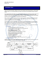
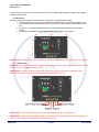
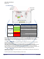
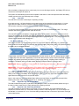
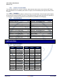
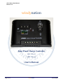
CHC-1224-xx User Manual Revision 1.0 windynation Solar Panel Charge Controller CHC-1224-10 CHC-1224-30 User’s Manual Page 1 of 1 windynation 07/19/2013 CHC-1224-xx User Manual Revision 1.0 Table of Contents 1 Introduction ................................................................................................................................................. 3 1.1 Features ............................................................................................................................................ 3 1.2 System Diagram ................................................................................................................................ 3 1.3 Safety Information ............................................................................................................................. 4 1.4 Specifications .................................................................................................................................... 4 1.4.1 Electrical Specifications................................................................................................................. 4 1.4.2 Physical Specifications .................................................................................................................. 4 2 Installation ................................................................................................................................................... 4 2.1 Electrostatic (ESD) Precautions ........................................................................................................ 4 2.2 Mounting............................................................................................................................................ 5 2.3 Connections....................................................................................................................................... 5 3 Operation .................................................................................................................................................... 6 3.1 Power ................................................................................................................................................ 6 3.2 LED Indicators ................................................................................................................................... 7 3.2.1 Charge LED................................................................................................................................... 7 3.2.2 Battery LED ................................................................................................................................... 7 3.2.3 Load LED....................................................................................................................................... 8 3.3 Setting Modes.................................................................................................................................... 8 3.3.1 Normal Control .............................................................................................................................. 8 3.3.2 Night ON+ Day OFF Control Mode ............................................................................................... 8 3.3.3 Night ON + Set Time Delay OFF Mode ......................................................................................... 8 3.3.4 Common Controller Mode ............................................................................................................. 9 3.3.5 Test Mode...................................................................................................................................... 9 3.3.6 Functional Matrix ........................................................................................................................... 9 4 Application .................................................................................................................................................. 9 4.1 Wire Gauge Reference...................................................................................................................... 9 4.1.1 Wire Thickness .............................................................................................................................. 9 5 Troubleshooting And Support ................................................................................................................... 10 5.1 Maintenance & Care........................................................................................................................ 10 5.2 Troubleshooting............................................................................................................................... 10 5.3 Support ............................................................................................................................................ 10 5.4 Warranty .......................................................................................................................................... 11 5.4.1 Restrictions.................................................................................................................................. 11 5.4.2 Warranty Claims & Return Procedures ....................................................................................... 11 5.4.3 Disclaimer.................................................................................................................................... 11 5.4.4 Limitation of Liability .................................................................................................................... 12 Page 2 of 2 windynation 07/19/2013 CHC-1224-xx User Manual Revision 1.0 1 INTRODUCTION The WindyNation Solar Panel Charge Controller provides a reliable charging and power management solution for solar power battery systems with many of the features that you would expect in a much higher priced controller. This is made possible by the board microprocessor and embedded intelligent software control. The controller features automatic a 12V or 24V DC detect function that will identify the battery voltage upon initial charge and uses Pulse-Width Modulation (PWM) for automatic charge management and high efficiency. A built in temperature sensor provides software controlled charge compensation that accurately adjusts the over-discharge voltage and maximizes your batteries life. Built in protection includes overload, short circuit, reverse connection, lightning/surge, PV panel reverse current, over charging, and discharging protection. In the event of a short circuit or overload event, the system will be protected and remain undamaged. The enclosure is made of durable plastic with LED lights to provide status indications of charge, battery status, and system faults as well a user selectable Work Mode/timing interval that will power various DC powered systems for specified time intervals after dusk such as night/street lighting. Please read this manual carefully before installing or using the controller and keep it for future reference. 1.1 FEATURES Compact size is easy to mount on wall or panel. Charge controller maintains batteries and extends battery life. Auto sensing for 12 or 24V systems Built-in battery test function Convenient screw terminals for wiring Separate connections for PV panel, battery, and load Built-in overload and short circuit protection Automatic self-recovery after fault removal LED system status indicators Requires no adjustments User selectable on, off, and time modes Wide operating temperature range -35˚C to +55˚C (-31˚F to +131˚F) 1.2 SYSTEM DIAGRAM The MCU controller takes sample measurements from the storage battery voltage, discharge current, and ambient temperature to calculate and control the discharge rate. Page 3 of 3 windynation 07/19/2013 CHC-1224-xx User Manual Revision 1.0 1.3 SAFETY INFORMATION Please read the installation and operating instructions carefully prior to use. Pay special attention to the IMPORTANT and WARNING statements in the manual. WARNING: Never install during a lightning storm or where unsafe voltages are present. Solar panels produce power when exposed to light. Use caution when handling copper wiring. Do not use with equipment that exceeds the rated power for this device. 1.4 SPECIFICATIONS 1.4.1 Electrical Specifications Parameter Rated Charge Current Rated Load Current Typical Idle Consumption Overvoltage Protection Low Voltage Indication Overload Protection (DC load) CHC-1224-10 10 Amps 10 Amps At idle < 5mA 15.6V 31.2V 12.0V 24.0V 1.25 x Inom>60s 1.5 x Inom >5s 3x Inom 14.6V 29.2V 13.6V 27.2V 14.4V 28.8V 14.8V 29.6V 13.2V 26.4 V 11.1V 22.2V 12.5V 25.0V o -4.0 mV/ C/2V Short Circuit Protection Boost Charge Float Charge Voltage Equalization Charge Overcharge Disconnection Overcharge Recovery Over-discharge Disconnection Over-discharge Reconnection Temperature Compensation 1.4.2 Physical Specifications Parameter Dimension (H x W x D) Unit Weight Operating Temperature Operating Humidity Wire Size Battery Type CHC-1224-30 30 Amps 30 Amps Value 5.26” (133.5mm) x 2.76” (70mm) x 1.34” (34mm) 0.3 lb. (142g) o o o o -31 F to 131 F (-35 C to 55 C) 20 to 80% relative humidity (non-condensing) 2 Up to 6mm Lead Acid including AGM and Flooded 2 INSTALLATION Insure all terminating connections are clean and tight to prevent arcing and overheating. The controller must be installed in an area that satisfies all of the following conditions: 1. Dry: Avoid any location where water can contact the controller 2. Cool: Ambient air temperature between 30°F and 105°F (0°C and 40°C) 3. Ventilated: Allow at least 2 in (50 mm) of clearance above and below and at least 1 in (25 mm) on each side for proper air flow. 2.1 ELECTROSTATIC (ESD) PRECAUTIONS All electronic circuits may be damaged by static electricity. To minimize the likelihood of electrostatic damage, discharge yourself by touching an electrical ground (e.g.: copper pipe) prior to handling the unit and Page 4 of 4 windynation 07/19/2013 CHC-1224-xx User Manual Revision 1.0 avoid touching components on the circuit boards. The risk of electrostatic damage is highest when relative humidity is below 40%. 2.2 MOUNTING Mounting is optional; however, the environment must be dry and protected from water. 1. The controller can be mounted on a vertical or horizontal surface. If mounted vertically, the unit should be oriented such that neither end is at the top so foreign material cannot settle into the unit. 2. Install four user-supplied fasteners through the four mounting slots and into the mounting surface. 3. Tighten all the fasteners to ensure the controller cannot slide in any direction. IMPORTANT: For best results, mount the charge controller and batteries as close to the panels as practical. 2.3 CONNECTIONS WARNING: Loose connectors result in excessive voltage drop and may cause over heated wires and melted insulation, which can lead to electrical fires. IMPORTANT: The NEC requires that the wires carrying the system current never exceed 80% of the conductor’s current rating (sizing recommendations are located in Section 4). IMPORTANT: The screw-down terminals on the charge controller accept 10~26AWG wire. IMPORTANT: Strip the wire ends approximately 0.2” (5mm) before connecting to the charge controller. Use caution when handling the stripped wires to avoid electric shock. Page 5 of 5 windynation 07/19/2013 CHC-1224-xx User Manual Revision 1.0 1) Connect the Battery Connect the battery wiring to the battery terminals on the charge controller. Note the polarity on the screwdown terminals. The charge controller self-protection feature will prevent damage from reverse polarity connections, but the charge controller will not function until the battery is connected properly. IMPORTANT: A properly sized fuse needs to be placed in the positive wire connecting the charge controller to the battery. 2) Connect the Solar Panel Array Connect the wires from the solar panel array to the PV port on the charge controller. Note the polarity on the screw-down terminals. The charge controller self-protection feature will prevent damage from reverse polarity connections, but the charge controller will not function until the solar panel array is connected properly. The green LED indicator will light up if there is enough sunlight. IMPORTANT: A properly sized fuse needs to be placed in the positive wire connecting the solar panel(s) to the charge controller. WARNING: High voltages may be present on the solar panel output wiring. Solar panels produce electricity when exposed to light. Use caution and avoid touching any conductors in the system circuit to avoid electric shock. 3) Connect the Load (Optional) If you have a 12VDC application, connect the wires from the appliance to the load port on the charge controller. Note the polarity on the screw-down terminals. The charge controller self-protection feature will prevent damage from reverse polarity connections, but the charge controller will not function until the load is connected properly. IMPORTANT: A properly sized fuse needs to be placed in the positive wire connecting the load (e.g. light bulb, etc.) to the charge controller. If the red LED indicator light turns on, the battery capacity is low and needs to be charged before completing the system installation. Press the Power/Mode button to turn on power to the load terminals. 3 OPERATION 3.1 POWER Once properly connected to a battery and solar panel array, the charge controller will immediately begin operating. When first connected, the Load LED will be off, indicating that the power to the load is off. Press the Power/Mode button to turn on power to the load. Note: The solar power charge controller can only be used with lead acid type batteries. To test the system for proper connections, press the Power/Mode button on the charge controller until you see the number 7. (or 17; see description below). IMPORTANT: Make sure the solar module(s) voltage and current do not exceed the ratings of the charge controller. Page 6 of 6 windynation 07/19/2013 CHC-1224-xx User Manual Revision 1.0 3.2 LED INDICATORS LED Charge State Description OFF No Charge (Nighttime) Solid Green Blinking Green Solid Green Battery Load Solar power is charging the battery The system is over voltage Battery level is in the right range Slow Flash Green Battery level is full Solid Yellow Battery level is low Solid Red Load cut-off Solid Red The output is on Slow Flash Red Blinking Red Overload Load is short circuit Note: The load output will shut off once there is an overload or short circuit. Disconnect all of the equipment and then wait a few seconds before reconnecting everything. Press the Power/Mode button and the controller will resume working after approximately 10 seconds, or in some instances, it may take a few moments longer. 3.2.1 Charge LED When the connected solar panel is exposed to sunlight, the Charge LED will be green, indicating that the system is charging normally. The Charge LED will flash green when an overcharge condition or an open battery circuit exists. PWM mode is used during charging. If an over-discharge of the battery has occurred, the charger will switch to boost voltage for 10 minutes, then will return to direct voltage for at least 10 minutes to activate the battery, and finally to the float voltage state where it will remain to maintain the best state of the battery. This multistep charging process will help bring the battery to full charge and maximize its life span. 3.2.2 Battery LED The Battery LED is green when the battery voltage is in normal condition. It will blink green slowly when the battery finishes its charge. The LED is yellow when the voltage of the battery is below normal. Page 7 of 7 windynation 07/19/2013 CHC-1224-xx User Manual Revision 1.0 When the battery voltage goes down continuously into an over-discharge condition, the Battery LED will turn red and the Load output will switch off. The system will automatically resume normal operation and switch on the load output and when the battery voltage recovers to the over-discharge return voltage. 3.2.3 Load LED The load LED is red when a load output is operating normally. If the load current is 1.25 times higher than the rated current of the controller for 60 seconds or 1.5 times higher than the rated current for 5 seconds, then the controller will shut down the output and the Load LED will blink red slowly to indicate that an overload condition occurred. To resume normal operation, disconnect the load at fault and press the Power/Mode button. The charge controller will resume normal operation after 30 seconds. The Load LED will blink red rapidly to indicate that a short circuit condition occurred. If a load short circuit occurs, the controller will shut down the output. If this happens, verify load connections. To resume normal operation, remove the short circuit at the load and press the Power/Mode button. The charge controller will resume normal operation after 30 seconds. 3.3 SETTING MODES The charge controller has a mode setting function to set specific operation parameters. It is preset to the factory default of normal control. The load will draw from the battery at all times, and the PV panel will charge the battery when sunlight is available. Press and hold un-l LED Flashes Press to Select Mode Number Release at desired mode, wait for blinking to stop Mode is set. Mode display turns off automa-cally To set modes, press and hold the Power/Mode Button until the number on the LED display begins to flash (~5 seconds). Press the button repeatedly to choose the desired mode number. When the desired number is selected, stop pressing the button and wait for number to stop flashing, indicating that the setting is completed. The display will turn off after several seconds. Press the button to check the value. IMPORTANT: Settings 10 through 17 may appear as a single digit and have a dot (.) after the mode number. IMPORTANT: The controller requires about 10 minutes of continuous transition values before it starts working properly. These constraints avoid false transitions due to lighting or shading. 3.3.1 Normal Control This is the default setting. The load will draw from the battery at all times, and the PV panel will charge the battery when sunlight is available. When selecting this mode (16 or 6-dot), press the Power/Mode button again after the mode is set to turn on the load output. Note: In this mode only, the Power/Mode button will turn the load output on and off when pressed. After selecting this mode, make sure the load LED is on, indicating load output. 3.3.2 Night ON+ Day OFF Control Mode The load will start working when it gets dark until it gets light. There is a 10 minute delay before turning on the load in order to make sure it is really dark and not a passing cloud etc. 3.3.3 Night ON + Set Time Delay OFF Mode The load will switch on same as above, and remain on for a set duration. Once the selected time has elapsed, the load will switch off. The duration setting is listed in mode setting table. 1 to 15 hour delays can be selected, in increments of 1 hour. If the time setting overlaps with the occurrence of light control, then light control takes priority. Page 8 of 8 windynation 07/19/2013 CHC-1224-xx User Manual Revision 1.0 3.3.4 Common Controller Mode The controller will work as a common controller, without light and time control, and no ON and OFF delay time. The load turns on immediately when there is no light, and off immediately when light is present on the PV panel. 3.3.5 Test Mode This is used for the testing the system by directly turning on the load output. If there is light signal (sunlight), the load will be turned off (closed). If there is no light signal (sunlight), the load will be turned on (opened). It is convenient for checking the correctness of the system during installation and debugging. 3.3.6 Functional Matrix MODE LED MODE LED Night ON + Day OFF 00 Night ON + 10 Hours delay OFF 10 or 0. Night ON + 1 Hour delay OFF 01 Night ON + 11 Hours delay OFF 11 or 1. Night ON + 2 Hours delay OFF 02 Night ON + 12 Hours delay OFF 12 or 2. Night ON + 3 Hours delay OFF 03 Night ON + 13 Hours delay OFF 13 or 3. Night ON + 4 Hours delay OFF 04 Night ON + 14 Hours delay OFF 14 or 4. Night ON + 5 Hours delay OFF 05 Night ON + 15 Hours delay OFF 15 or 5. Night ON + 6 Hours delay OFF 06 Normal Control 16 or 6. Night ON + 7 Hours delay OFF 07 Test (no delay) 17 or 7. Night ON + 8 Hours delay OFF 08 Night ON + 9 Hours delay OFF 09 4 APPLICATION 4.1 WIRE GAUGE REFERENCE 4.1.1 Wire Thickness Diameter AWG inches (mm) 16 0.051 (1.29) Page 9 of 9 Ohms per 1000ft 4.016 Break Force 75 lbs Square mm2 1.30 14 0.064 (1.63) 2.525 119 lbs 2.08 12 0.081 (2.05) 1.588 197 lbs 3.30 10 0.102 (2.59) 0.999 314 lbs 5.26 8 0.129 (3.26) 0.628 480 lbs 8.30 6 0.162 (4.11) 0.395 760 lbs 13.30 4 0.204 (5.19) 0.249 1210 lbs 21.15 2 0.258 (6.54) 0.156 1930 lbs 33.62 1 0.289 (7.35) 0.124 2430 lbs 42.41 0 (1/0) 0.325 (8.25) 0.098 3060 lbs 53.49 00 (2/0) 0.365 (9.27) 0.078 3860 lbs 67.43 000 (3/0) 0.410 (10.4) 0.062 4860 lbs 85.01 0000 (4/0) 0.460 (11.68) 0.049 6120 lbs 107.22 windynation 07/19/2013 CHC-1224-xx User Manual Revision 1.0 5 TROUBLESHOOTING AND SUPPORT The Controller requires minimal care. It is recommended to inspect all the connections at least two times per year for insulation damage or corrosion and to ensure all connections are tight and secure. 5.1 MAINTENANCE & CARE Clean the area around the controller of any dirt or debris with a moistened cloth. Tighten the screws on the DC input terminals. Inspect for loose, broken, or burnt wire connections. Inspect any batteries for cracked or bulging cases and corroded terminals. Make sure the PV array is clean and remove any debris. 5.2 TROUBLESHOOTING Problem Possible Remedies 1. Check if the solar panel cables are connected properly. 2. Check to make sure the correct battery is being used. 3. Check all wiring connections to make sure they are in their designated locations and make sure that there are no loose connections. The charge LED indicator 4. Measure the PV array open-circuit voltage and confirm it is within its normal doesn't light green when limits. the solar panel is exposed 5. Measure the PV voltage and the battery voltage at the controller terminals. to sunlight. a. If the voltage at the terminals is within proper specifications, the PV array is charging the battery properly. b. If the PV voltage is within specifications to the open circuit voltage rating of the panels, but the battery voltage is low, the charge controller may not be charging the battery and it may be damaged. 1. System over voltage protection is active. 2. Check for open circuit in battery, faulty battery connections to the system, or system charging circuit failure. The charge LED indicator 3. Check the operating conditions to confirm that the voltage is higher than the flashes rapidly. specifications. a. Consider temperature compensation. For example, at 0°C the charge controller will regulate at about 15 volts. The load LED indicator is on but there is no power output. The load LED indicator light flashes and there is no power output. 1. Load open circuit. 2. Check cables and connections and any other load switches. 3. Over discharge of the battery. The controller will resume normal operation after the battery has finished charging. 1. Check the output circuit for load short circuit or over load condition 2. Remove the load and push the button; the controller will resume its work after 30 seconds. 5.3 SUPPORT If you are experiencing technical problems, and cannot find a solution in this manual, you can contact Windy Nation Inc. for further assistance. • Call: (805) 323-6445 • Email: [email protected] • Write: 398 South Kalorama Street, Unit C, Ventura, CA 93001 For challenging issues or to just ask a question, consider using our FREE Community Forums! Consult our community of DIY'ers for fast answers to all your questions. Page 10 of 10 windynation 07/19/2013 CHC-1224-xx User Manual Revision 1.0 Post on our Forums: http://www.windynation.com/community/ 5.4 WARRANTY Windy Nation warrants that the Power Controller (the “Product”), will be free from manufacturing defects in materials and workmanship under normal authorized use consistent with product instructions for a period of one (1) year from the date the original purchaser (“Customer”) receives the Product (the “Warranty Period”). This warranty extends only to the original purchaser. The Customer’s sole and exclusive remedy and the entire liability of Windy Nation, its suppliers and affiliates for breach of the warranty is, at Windy Nation’s option, either (i) to replace the Product (or defective component part(s)) with a new or reconditioned Product (or component part(s)); (ii) to repair the reported problem; or (iii) to refund the purchase price of the Product. Repaired or replaced products are warranted for the remainder of the original warranty period only. No employee, agent, dealer or other person is authorized to give any warranties on behalf of Windy Nation not expressly set forth in this limited warranty. 5.4.1 Restrictions No warranty will apply if the Product (i) has been altered or modified except by Windy Nation; (ii) has not been installed, operated, repaired, or maintained in accordance with instructions supplied by Windy Nation; (iii) has been subjected to abnormal physical, thermal or electrical stress, misuse, negligence, or accident. If Windy Nation determines that the problem with the Product is not due to a manufacturing defect in Windy Nation’s workmanship or materials, or otherwise does not qualify for warranty repair, then the Customer will be responsible for the costs of all necessary repairs and expenses incurred by Windy Nation. 5.4.2 Warranty Claims & Return Procedures To be eligible for service under this warranty, the Customer must submit a service request within the Warranty Period by contacting Windy Nation in writing or via telephone and obtaining a Returned Materials Authorization (“RMA”) number. This RMA must be obtained before returning any product under this warranty. Notification must include a description of the alleged defect, the manner in which the Product was used, the serial number, and the original purchase date in addition to the name, address, and telephone number of the Customer. Within five (5) business days of the date of notification, Windy Nation will provide the Customer with an RMA number and the location to which the Customer must return the defective Product. Any Product returned for warranty service shall be shipped at the expense and risk of the Customer. The Customer must return the entire Product kit (or, if authorized by Windy Nation, the defective component parts), within fifteen (15) days after issuance of the RMA number. Windy Nation will be under no obligation to accept any returned Product that does not have a valid RMA number. Customer’s failure to return the Product within fifteen (15) days of its receipt of an RMA number may result in cancellation of the RMA. All parts that Windy Nation replaces shall become Windy Nation’s property on the date Windy Nation ships the repaired Product or part back to the Customer. Windy Nation will use all reasonable efforts within thirty (30) days of receipt of the defective Product to repair or replace such Product. If a warranty claim is invalid for any reason, the Customer will be charged at Windy Nation’s then-current rates for services performed and will be charged for all necessary repairs and expense incurred by Windy Nation. If Windy Nation determines that a warranty claim is valid, it will ship the repaired or replaced Product to Customer at Windy Nation’s cost. 5.4.3 Disclaimer EXCEPT FOR THE EXPRESS LIMITED WARRANTY SET FORTH IN THE PREVIOUS PARAGRAPH, WINDY NATION DISCLAIMS ALL WARRANTIES, EXPRESS, IMPLIED AND STATUTORY INCLUDING, WITHOUT LIMITATION, THE IMPLIED WARRANTIES OF MERCHANTABILITY AND FITNESS FOR A Page 11 of 11 windynation 07/19/2013 CHC-1224-xx User Manual Revision 1.0 PARTICULAR PURPOSE WITH RESPECT TO ANY PRODUCTS PROVIDED BY WINDY NATION. NO ORAL OR WRITTEN INFORMATION OR ADVICE GIVEN BY WINDY NATION, ITS DEALERS, DISTRIBUTORS, AGENTS OR EMPLOYEES SHALL IN ANY WAY INCREASE THE SCOPE OF THIS WARRANTY. WINDY NATION DOES NOT WARRANT THAT THE QUALITY OR PERFORMANCE OF THE PRODUCTS WILL MEET YOUR REQUIREMENTS OR THAT YOU WILL BE ABLE TO ACHIEVE ANY PARTICULAR RESULTS FROM USE OR MODIFICATION OF THE PRODUCTS. Some jurisdictions do not allow the limitation or exclusion of implied warranties or how long an implied warranty may last, so the above limitations may not apply to you. In any such jurisdiction, the warranty shall be limited to the minimum warranty and period required by law. WINDY NATION EXPRESSLY DISCLAIMS ALL LIABILITY FOR BODILY INJURIES OR DEATH THAT MAY OCCUR, DIRECTLY OR INDIRECTLY, BY USE OF THE PRODUCT BY ANY PERSON. 5.4.4 Limitation of Liability UNDER NO CIRCUMSTANCES WILL WINDY NATION OR ITS AFFILIATES OR SUPPLIERS BE LIABLE OR RESPONSIBLE FOR ANY LOSS OF USE, INTERRUPTION OF BUSINESS, LOST PROFITS, LOST DATA, OR INDIRECT, SPECIAL, INCIDENTAL, OR CONSEQUENTIAL DAMAGES OF ANY KIND REGARDLESS OF THE FORM OF ACTION, WHETHER IN CONTRACT, TORT (INCLUDING NEGLIGENCE), STRICT LIABILITY OR OTHERWISE, EVEN IF WINDY NATION OR ITS AFFILIATE OR SUPPLIER HAS BEEN ADVISED OF THE POSSIBILITY OF SUCH DAMAGE. Some states do not allow the exclusion or limitation of incidental or consequential damages, so these limitations may not apply to you. Neither Windy Nation nor its affiliates or suppliers will be held liable or responsible for any damage or loss to any items or products connected to, powered by or otherwise attached to the Product. The total cumulative liability to Customer, from all causes of action and all theories of liability, will be limited to and will not exceed the purchase price of the Product paid by Customer. This warranty gives the Customer specific legal rights and the Customer may also have other legal rights that vary from state to state. Page 12 of 12 windynation 07/19/2013