1
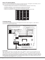
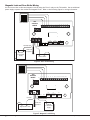
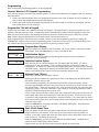
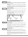
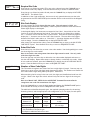
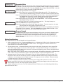
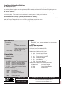
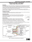
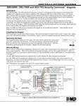
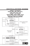
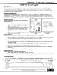
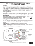
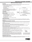
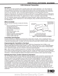
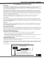
Installation Sheet
734 Wiegand Interface Module
Description
The 734 Wiegand Interface Module allows you to use the powerful built-in access control capability of DMP Command
Processor™ Panels. The XRSuper6, XR20, XR40, XR100, XR500 Series and XR2500F panels provide system door
control, arming, and disarming using proximity or mag-stripe devices. The 734 Module easily connects to the keypad
bus of any of the panels listed above.
The 734 operates on 12 VDC input and provides four power-limited programmable zones. Zones 1, 2 and 3 can be
programmed for a variety of burglary or access control applications. Zone 4 is a Class B, Style A circuit that can be
programmed as a fire zone. Additionally, the module supplies a Form C Single Pole Double Throw (SPDT) Door Strike
relay, built-in piezo with remote annunciation output, data to panel LED, and a 4-position terminal for connecting
one or more external Wiegand format readers.
The Form C relay draws up to 35mA of current and its contacts are rated for 10 Amps at 12 VDC. Refer to the
NC/C/NO (Dry Contact Relay) and the Isolation Relay sections in this document for more information.
Access Control
The 734 module allows users to present an access credential, such as a card or keyfob, to a Wiegand reader. The
reader then sends the Wiegand input to the 734 module that reads the user code and verifies its authority with the
panel. After verifying the code has the proper authority, the 734 module powers its on-board Form C relay releasing
a door strike or magnetic lock.
Enroll Users
DMP 793 Security Command or 7063, 7063A, 7073, 7073A, 7163 or 7173 Thinline LCD keypads can be used to enroll
users. Remote Link™ or System Link™ with an Admin Reader can also be used to quickly enroll users in the system.
The 734 cannot be used to enroll users.
Mount the 734 to Walls
The 734 ships installed in a decorative, high-impact plastic case that mounts directly to walls, backboards, or other
flat surfaces. For easy installation, the 734 housing back and both ends have wire entrances. The bottom half of the
plastic case contains two screw holes for mounting the case on single-gang switch boxes. It is recommended that
you mount the 734 near the protected door.
Mount the 734 in Panel Enclosures
You can also install the 734 in a panel enclosure using the standard 3-hole mounting configuration.
1.Mount the plastic standoffs to the enclosure using the three included Phillips head screws.
2.Insert the screws through the holes on the enclosure exterior side and into the plastic standoffs which mount on
the enclosure inside. Tighten the screws into place.
3.After tightening and securing the standoffs onto the enclosure, snap the 734 onto the standoffs.
Install the 333 Suppressor
One Model 333 Suppressor is included with the 734 module. Install the suppressor across the 734 Common (C) and
Normally Open (NO) or Normally Closed (NC) terminals on J1.
If the device being controlled by the relay is connected to the NO and C terminals, install the suppressor on the NO
and C terminals. Conversely, if the device is connected to the NC and C terminals, install the 333 Suppressor on NC
and C terminals.
The suppressor wire is non-polarized. Install the suppressor as shown in Figure 1.
734 Interface Module
C
NC
J2
J1
RED
YEL
J4
J5
Piezo
GRN
RELAY WIEGAND DATA
ON
READ LED XMT LED
RED
NO
PROG RED
+
–
KYPD IN RED KYPD OUT
Model 333 Suppressor
Wire the Suppressor to the Common and Normally Open or Normally
Closed depending upon which terminals are used for the device.
Figure 1: Model 333 Installation on the 734 Module
Set the 734 Module Address
The 734 is a supervised module and cannot operate in unsupervised mode. To change the current address, refer to
Figure 2 and move the slide switches to the appropriate address positions.
•
•
•
•
XRSuper6 and XR20 panels use addresses 1 to 4 and automatically recognize the switch setting
The XR40 use addresses 1 to 8 and automatically recognize the switch setting
XR100 Series use addresses from 1 to 8 in panel programming Device Setup
XR500 Series and XR2500F use addresses from 1 to 16 in panel programming Device Setup.
ON
ON
1
ON
2
1 2 3 4
4
1 2 3 4
ON
1 2 3 4
6
1 2 3 4
8
1 2 3 4
ON
9
1 2 3 4
ON
14
ON
15
1 2 3 4
1 2 3 4
12
1 2 3 4
ON
13
ON
11
1 2 3 4
ON
1 2 3 4
ON
10
1 2 3 4
ON
7
1 2 3 4
ON
1 2 3 4
ON
ON
5
ON
3
16
1 2 3 4
1 2 3 4
Figure 2: 734 Addresses
734 Module Wiring
The 734 connects to the keypad data bus and a Wiegand format reader. Refer to Figures 3, 4, and 5 and the
instructions in this guide for proper wiring.
Remote LED Control
Remote Audible Annunciator
Note: Only use shielded wire if specified by the reader
manufacturer. Only connect the shield to the reader.
Refer to reader installation documentation for more
information.
Armed Status Output
Note: Use 1K Ohm EOL for each zone.
Zone 1
Black
Green (Data 0)
White (Data 1)
Zone 2
Zone 3
Red
Shield
Card Reader
Zone 4
734
Interface
Module
1
3
4
5
RED WHT GRN BLK LC
ON
S1
NO
2
C
9
10
6
7
8
RA
AS
Z1 GND Z2
11
12
13
14
J3
+
12
V
D
C
D
a
t
a
1
D
a
t
a
0
Z3 GND Z4+ Z4–
G
N
D
NC
J2
RED
YEL
RELAY WIEGAND DATA
ON
READ LED XMT LED
Model 333
Supressor
J4
J5
Piezo
GRN
RED
J1
PROG
RED
+
–
KYPD IN RED KYPD OUT
Maximum line impedance is 100 Ohms
Zone 4 Ground fault detected at 1420 Ohms or less
Normal operating range is 650 - 1200 Ohms
Figure 3: 734 Wiring Diagram
Card Reader
Figure 3 shows a reader with wire colors Red, White, Green, and Black. The wire colors may be different for the
reader being installed. Connect the reader wires to J3 terminals 1, 2, 3, and 4. As shown in Figure 3, the Green
wire carries D0, or Data Zero, and the White wire carries D1, or Data One. The Red wire carries 12 VDC output and
the Black wire is ground. Refer to the literature provided with the reader for wire coding, wire distance, cable type
(such as shielded), and other specifications. If you are powering the readers from an auxiliary power source, refer
to 12 VDC Access Control Readers later in this document.
Digital Monitoring Products
2
734 Installation and Programming Guide
LC (Remote LED Control)
Terminal 5 provides an unsupervised switched ground for a visual indicator that turns on when the Model 734 relay
activates. Connect the negative side of an LED controller to J3 terminal 5. The LED turns on for the duration the
door strike relay is on.
Note: HID readers optionally provide a connection for LED reader control.
RA (Remote Annunciation)
Terminal 6 provides an unsupervised switched ground for a remote annunciator (RA) that turns on when the Model
734 on-board piezo turns on. Connect the negative side of a remote annunciator to J3 terminal 6. The remote
annunciator activates when the RA switches to ground. The remote annunciator silences when the RA restores.
AS (Armed Status)
Terminal 7 provides an unsupervised switched ground for a visual or audible armed status indicator that turns on
when the area Armed Status is sent to the 734 such as SYSTEM ON or ALL SYSTEM ON. Connect the negative side
of an Armed Status output to J3 terminal 7. The AS terminal may stay grounded up to 20 seconds after the system
disarms.
Zone Terminals
Terminals 8 through 12 on J3 connect grounded zones 1 through 3. These zones have a grounded side and cannot
be used for fire-initiating devices. Zones 2 and 3 can also be used for access control with Zone 2 providing a SoftShunt™ feature and Zone 3 providing Request to Exit functionality. Zone 4 terminals provide a non-powered Class B
ungrounded zone suitable for connection to fire devices such as 4-wire smoke or heat detectors. Refer to LT-0164
for a current list of 4-wire smoke detectors. Use the supplied, DMP Model 311 1K Ohm End-of-Line resistors on each
zone. Refer to the panel programming guide for programming instructions.
Note: A mechanical means of resetting four-wire smoke detectors or other latching devices on Zone 4 must be
provided. The panel does not drop power to the keypad bus when a Sensor Reset is performed.
NC/C/NO (Dry Contact Relay)
The 734 also provides an internal Form C (SPDT) relay for controlling door strikes or magnetic locks. The three relay
terminals on J1 marked NC C NO allow you to connect the device wiring to the relay for module control. See Figures
4 and 5 for proper door strike and magnetic lock wiring.
The Form C relay draws up to 35mA of current and its contacts are rated for 10 Amps at 12 VDC.
When connecting multiple locks to the Form C relay, the total current for all locks cannot exceed
10 Amps. If the total current for all locks exceeds 10 Amps, problems may arise and an isolation relay
may be needed.
KYPD IN (Keypad In)
Receives and transmits data to the panel Keypad bus.
KYPD OUT (Keypad Out)
Transmits keypad bus data out to other keypad(s) or modules. Install a dual connector four-position harness to allow
daisy chain connection to keypad(s) or other devices, up to the maximum number of devices supported by the bus.
PROG (Programming)
The 734 module is programmable from a 32-character keypad set to address one. Connect the keypad to the board
using a Model 330 4-wire harness. Programming starts as soon as the keypad is connected.
Status LEDs
The 734 board contains three status LEDs. The Red LED turns on for the duration that the door strike relay is
activated. The Yellow LED turns on for one second to indicate receipt of a Wiegand input. The Green LED indicates
data sent to the panel.
12 VDC Power
You can power the 734 module from a 12 VDC power source. The 12 VDC power can be provided by the panel or
from a separate listed burglary and fire alarm auxiliary power supply. Do not ground the power supply to the 734 or
Command Processor™ panel. Power Supplies must have battery backup and be power limited.
Direct Voltage Output to Reader
The 734 provides direct 12 VDC output to the reader on the J3 Red terminal connection. The 734 contains an onboard current limiting device that protects the 734 from shorts on the output voltage through external wiring.
734 Installation and Programming Guide
Digital Monitoring Products
3
Magnetic Lock and Door Strike Wiring
You can control door strikes and magnetic locks by using the Form C relay on the 734 module. Use an additional
power supply to power door strikes and magnetic locks. Refer to the following figures for wiring information.
734
Interface
Module
Card Reader
2
1
3
4
5
10
6
7
8
9
RA
AS
Z1 GND Z2
11
12
13
14
J3
RED WHT GRN BLK LC
ON
Z3 GND Z4+ Z4–
S1
NO
C
NC
J2
RED
YEL
J5
Piezo
GRN
RELAY WIEGAND DATA
ON
READ LED XMT LED
Normally Open
J4
RED
J1
RED
PROG
+
–
KYPD IN RED KYPD OUT
Common
Model 333
Supressor
DMP 502
or 505 Power
Supply
+
–
DC Door Strike
Figure 4: Door Strike Wiring
Card Reader
734
Interface
Module
1
2
3
4
5
9
10
6
7
8
RA
AS
Z1 GND Z2
11
12
13
14
J3
RED WHT GRN BLK LC
ON
Z3 GND Z4+ Z4–
S1
NO
C
NC
J2
Common
–
+
Magnetic Door Lock
RED
YEL
J4
J5
Piezo
GRN
RELAY WIEGAND DATA
ON
READ LED XMT LED
RED
J1
PROG
RED
+
–
KYPD IN RED KYPD OUT
Normally Closed
Model 333
Supressor
DMP 502
or 505 Power
Supply
Figure 5: Magnetic Lock Wiring
Digital Monitoring Products
4
734 Installation and Programming Guide
Programming
Refer to the panel programming guide for zone programming.
Connect Wire for LCD Keypad Programming
After you have properly wired the 734 interface module, connect the 32-character LCD keypad to the 734 following
the steps below:
1. Connect the standard model 330 4-wire programming harness to the 4-pin J2 header on the 734 module. Be
sure to match the module Red pin and harness Red wire.
2. Connect the other end of the programming harness to the 4-pin header on the back of the keypad. Be sure
that the Red wire is on the lowest pin.
Program the 734 with a Keypad
Program the 734 module with a DMP 32-character LCD keypad. The keypad used for programming must be set to
address 1 and supervised operation. Programming mode is automatically enabled when the keypad is connected.
When you remove the keypad, programming automatically stops and all data entered up to that point is saved.
Note: While in programming mode no 734 communication with the panel can occur.
While programming the 734 module with a keypad, advance to the next programming option by pressing the
COMMAND key. Return to the previous programming option or erase an incorrect entry by pressing the Back Arrow
key. Make a selection by pressing the Select key below the option you wish to select.
734 Programming
VER vvv mm/dd/yy
Program Start Display
INITIALIZE ALL?
NO YES
Initialization Option
ARE YOU SURE?
YESNO
Initialize Confirm Option
ACTIVATE ZONE 2
SHUNT: NO YES
Activate Zone 2 Shunt
When you connect the keypad to the 734 module, the version number and version release
date display. Press the COMMAND key to move to INITIALIZE ALL?.
Initialization sets the 734 module programming memory back to factory defaults in
preparation for programming.
After selecting YES to clear the memory, the 734 displays ARE YOU SURE? YES NO for
confirmation to clear the memory. This is a safeguard against accidentally erasing all
programming. No memory is cleared from the programming until you answer YES to the ARE
YOU SURE? option. Selecting NO displays the INITIALIZE ALL? option. Press the Back Arrow to
return to the INITIALIZE ALL? option with no programming changes saved.
Select YES to activate the Soft-Shunt™ option.
Selecting NO allows standard zone operation on Zone 2 and displays the ACTIVATE ZONE 3
REX option. Default setting is NO.
If the door being released by the 734 module is protected (contact installed), you can
provide a programmable Soft-Shunt entry/exit timer by connecting its contact wiring to the
734 module Zone 2. When the on-board Form C relay activates and the user opens the door
connected to Zone 2, the zone is shunted for the number of seconds programmed in ZONE 2
SOFTSHUNT TIME allowing the user to enter/exit.
If Zone 2 does not restore (door closed) within the programmed time minus ten seconds, the
piezo sounds every other second during the timer last ten seconds. If Zone 2 restores prior
to the end of the programmed second timer, the piezo silences. If the zone does not restore
after the ten second piezo time, the 734 ends the shunt and indicates the open or short zone
condition to the panel.
Press the COMMAND key to display the ZONE 2 SOFTSHUNT TIME option. The Back Arrow
returns to the previous menu.
ZONE 2 SOFTSHUNT
TIME:
40
Zone 2 Soft-Shunt Time
Enter the number of Soft-Shunt seconds to elapse before the Soft-Shunt timer expires.
Range is from 20 to 250 seconds. Press any top row select key to enter the number of
seconds. If the door remains open when the timer expires a zone open/short is sent to the
panel for Zone 2. The default is 40 seconds.
Press the COMMAND key to move forward to RELOCK ON ZONE 2 FAULT. The Back Arrow
returns to the ACTIVATE ZONE 2 SHUNT option.
Figure 6 shows how the Soft-Shunt works using the default 40 second timer.
734 Installation and Programming Guide
Digital Monitoring Products
5
5 Second
Strike
10 seconds before
the shunt time expires,
40
the device beeps if
Seconds
the door is still open.
40-Second "Soft-Shunt"
and entry/exit timer.
A zone open/short is
indicated if the door
remains open.
End of
timer.
Figure 6: Soft-Shunt™ Time line using default time
RELOCK ON ZONE 2
FAULT? NO YES
Relock on Zone 2 Fault?
Selecting NO leaves the relay on when Zone 2 faults to an open or short condition during
Soft-Shunt. Selecting YES turns the relay off when Zone 2 faults open or short during SoftShunt. The default is NO.
Press the COMMAND key to display ACTIVATE ZONE 3 REX:. The Back Arrow returns to the
ZONE 2 SOFTSHUNT TIME: option.
ACTIVATE ZONE 3
REX: NO YES
Activate Zone 3 Request to Exit
Selecting YES activates the Zone 3 Request to Exit (REX) option.
Selecting NO allows standard zone operation on Zone 3 and displays the ACTIVATE ONBOARD
SPEAKER option. Default setting is NO.
Optionally connect a PIR (or other motion sensing device) or a mechanical switch to Zone
3 to provide REX capability to the system. When Zone 3 shorts, the on-board Form C
relay activates for the programmed number of seconds. During this time, the user can
open the protected door to start the programmed Soft-Shunt™ entry/exit timer. After the
programmed number of seconds, the relay restores the door to its locked state.
The 734 module provides a shunt-only option for REX on Zone 3. When Zone 3 opens from
a normal state, only a Soft-Shunt occurs: the on-board relay does not activate. This shuntonly option uses two methods of REX. The first REX device provides the programmed SoftShunt entry/exit timer. The second REX device, or manual device such as a door knob,
unlocks the door.
An example of the shunt-only configuration is a door to an office that is locked 24 hours a
day. Users pass a REX motion detector positioned by the door to begin the programmed exit
timer. Within the programmed number of seconds the user must then manually activate a
second device, such as a REX device or manual door knob, to unlock the door. If the door is
opened after the programmed number of seconds, the zone goes into alarm.
If you select YES, pressing the COMMAND key displays ZONE 3 REX STRIKE TIME. The Back
Arrow returns to the ACTIVATE ZONE 2 SHUNT option.
ZONE 3 REX STRIKE
TIME:
5
Zone 3 REX Strike Time
Enter the number of REX seconds to elapse. Range is from 5 to 250 seconds. Press any
select key to enter the number of seconds. The default is 5 seconds.
Press the COMMAND key to move forward to the ACTIVATE ONBOARD SPEAKER option. The
Back Arrow returns to ACTIVATE ZONE 3 REX.
ACTIVATE ONBOARD
SPEAKER:NO YES
Activate Onboard Speaker
Select YES to enable the onboard piezo speaker for local annunciation. Select NO to turn
the piezo off for all operations. This does not affect remote annunciator open collector (RA)
operation. The default is YES.
Press the COMMAND key to display the CARD OPTIONS option. The Back Arrow returns to
ACTIVATE ZONE 3 REX.
Digital Monitoring Products
6
734 Installation and Programming Guide
CARD OPTIONS
DMP
CUSTOM
Card Options
Select DMP to indicate the reader sends a 26-bit DMP data string. To save the DMP option,
press the left top row Select key under DMP. Press the COMMAND key to display REQUIRE
SITE CODE. Default is DMP.
Note: When set to DMP, the 734 converts the last 17 bits of the 26-bit data string into a
5-digit number.
Select CUSTOM if using a non-DMP card. To select CUSTOM press the right top row Select key
under CUSTOM. Press the COMMAND key to display the WIEGAND CODE LENGTH option and
other options to configure the 734 for operation with the card. The Back Arrow returns to
ACTIVATE ONBOARD SPEAKER:.
WIEGAND CODE
LENGTH:
45
Custom Card Definitions
When using a custom product, enter the total number of bits to be received in Wiegand code
including parity bits.
Press any top row Select key to enter a number between 0-255 to equal the number of bits.
Default is 45 bits.
Typically, an access card contains data bits for a site code, a user code, and start/stop/
parity bits. The starting position location and code length must be determined and
programmed into the 734 Module.
Press the COMMAND key to save the bit number and access SITE CODE. The Back Arrow
returns to the CARD OPTIONS: option.
011101011100110101000110011000101
First Bit
received
Bit = 0
Position = 0
Site Code
Bit = 1
Position = 1
Length = 10
User Code
Bit = 0
Position = 11
Length = 20
Last Bit
received
Bit = 1
Position = 32
in this example the Wiegand Code Length = 32 bits.
Figure 7: Data Stream Bit Location Example
SITE CODE
POS: ppp LEN: xx
Site Code Position
Enter the site code start position in the data string. Then enter the number of characters
the site code contains.
PPP = the bit position in the string that indicates the site code start position. Press the
second Select Key to enter a number between 0-255. Default is 1. Press the COMMAND key
to save the entry.
XX = the total number of site code bits used. Press the fourth (right) Select Key to enter a
number between 1-16. Default is 1. Press the COMMAND key to save the entry.
Press the COMMAND key to display the USER CODE option. The Back Arrow key returns to the
WIEGAND CODE LENGTH: option.
USER CODE
POS: ppp LEN: xx
User Code Position
Define the User Code start bit position and number of User Code bits as follows.
PPP =the bit position in the string that indicates the User Code start position. Press the
second Select Key to enter a number between 0-255. Default is 1. Press the COMMAND key
to save the entry.
XX =the total number of User Code bits used. Press the fourth Select Key to enter a custom
number. Custom numbers can only be a number between 16-32. Press the COMMAND key to
save the entry. The default is the DMP value of 45 which is pre-programmed.
Press the COMMAND key to display REQUIRE SITE CODE. The Back Arrow returns to SITE CODE
POSITION: option.
734 Installation and Programming Guide
Digital Monitoring Products
7
REQUIRE SITE
CODE: NO YES
Require Site Code
Press the top row Select key under YES to use a site code and press the COMMAND key to
view the site code entry display. Press the Back Arrow key to return to CARD OPTIONS:.
Press the top row Select key under NO and press the COMMAND key to display NO OF USER
CODE DIGITS. The default is NO.
In addition to User Code verification, door access is only granted when any one site code
programmed at the SITE CODE ENTRY option matches the site code received in the Wiegand
string.
aaa bbb ccc ddd
eee fff ggg hhh
Site Code Display
You can program up to eight three-digit site codes. Site code range is 0-999. Any
previously programmed site codes display. Dashes represent blank site codes and indicate
where digits display on the keypad.
In the keypad display, the letters aaa correspond to Site Code 1, letters bbb to Site Code
2 and so on to hhh representing Site Code 8. Press the left top row Select Key to display
the ">" character next to the Site Code 1 (aaa) location. Press the left Select key again to
display the ">" character next to Site Code 5 (eee) location. The next Select key toggles
between Site Codes 2 and 6 and so on. Ensure the ">" character displays next to the site
code to change. Press the COMMAND key to display ENTER SITE CODE.
After entering all required site codes, press the COMMAND key to move to the NO OF USER
CODE DIGITS: option. Press the Back Arrow key to return to REQUIRE SITE CODE:.
ENTER SITE CODE
127 ___ ___ DEL
Enter Site Code
Press the left top row Select key to enter a site code number. Use the keypad digits to enter
the three-digit site code number.
Note: A card with a site code greater than three digits cannot be used. Use only cards
with three-digit site codes.
Press the right top row Select key to delete the site code number displayed and return to
the site code display. Repeat these steps to change, delete, or add other site codes. When
all site codes are entered, press the COMMAND key to display the NO OF USER CODE DIGITS:
option. Press the Back Arrow key to return to REQUIRE SITE CODE:.
NO OF USER CODE
DIGITS:
5
Number of User Code Digits
The 734 module recognizes user codes from four to eight digits in length. Press any top row
Select key to enter a user code digit length between 4-8 digits. This number must match the
user code number length being used by the panel. Default is 5.
When searching the bit string for the user code, the digits are identified and read from left
to right. When a four-digit user code is selected only the first four digits of the string are
read.
Note: As of March 2005, XR500 Series and XR2500F Command Processor® Panels
recognize a user code with a maximum of 6-digits.
Press the COMMAND key to save the digit number and display the DEGRADED MODE option.
Press the Back Arrow key to return to REQUIRE SITE CODE: option.
The table below identifies the panel types, the required operating modes for the arming/
disarming feature, and the appropriate code configuration (4, 5 or 6 digits) for each panel.
Operation
XRSuper6 XR20/XR40
Arms H/A
4-digit
4-digit
Disarms H/A
4-digit
4-digit
Arms A/P
N/A
N/A
Disarms A/P
4-digit
4-digit
Arms Area(s)
—
N/A
Disarms Area(s)
—
4-digit*
* During entry delay only.
— Not available on this panel type.
N/A Requires additional selection to arm.
Digital Monitoring Products
8
XR500 Series/XR2500F
N/A
4-digit
N/A
4-digit
N/A
4,5 or 6-digit
734 Installation and Programming Guide
DEGRADED MODE
RELAY ALWAYS OFF
Degraded Mode
REMOVE KEYPAD
Remove Keypad
This option defines the relay action when communication with the panel has not occurred for
five seconds. Press any top row Select key to display CHOOSE ACTION to change the default
relay action Relay Always Off. Press the COMMAND key to display REMOVE KEYPAD. Press the
Back Arrow key to return to the NO OF USER CODE DIGITS:.
CHOOSE ACTION
Choose the Degraded Mode Action required.
off SITE ANY ON
Press the first Select key to choose OFF [Default] (Relay Always Off) — The relay does not
turn on when any Wiegand string is received. Off does not affect any REX operation.
Press the second Select key to choose SITE (Accept Site Code) — Door access is granted when
the Wiegand site code string received matches any site code programmed at SITE
CODE ENTRY. For details refer back to the REQUIRE SITE CODE option..
Press the third Select key to choose ANY (Any Wiegand Read) — Door access is granted when
any Wiegand string is received.
Press the fourth Select key to choose ON (Relay Always On) — The relay is always on.
CHOOSE ACTION
Press the COMMAND key to display the next action.
LAST
Press the first Select key to choose LAST (Keep Last State) — The relay remains in the same
state and does not change when communication is lost.
After choosing the action, the DEGRADED MODE option and the newly defined action display.
Programming is now complete. Press the COMMAND key to display REMOVE KEYPAD. Press
the Back Arrow to return to the NO OF USER CODE DIGITS option.
The REMOVE KEYPAD option continually displays with no time out while the keypad remains
connected to the 734 module after programming is finished. After five seconds the 734
module piezo continually sounds if the keypad remains connected and programming is
finished. Remove the keypad harness to disconnect the keypad from the 734 module and
silence the alarm.
Wiring Specifications
Refer to the following LX-Bus and Keypad bus wiring specifications.
1. DMP recommends using 18 or 22-gauge unshielded wire for all keypad and LX-Bus circuits. Do not use twisted
pair or shielded wire for LX-Bus and keypad bus data circuits. All 22-gauge wire must be connected to a
power-limited circuit and jacket wrapped.
2. On keypad bus circuits, to maintain auxiliary power integrity when using 22-gauge wire do not exceed 500
feet. When using 18-gauge wire do not exceed 1,000 feet. To increase the wire length or to add devices,
install an additional power supply that is listed for Fire Protective Signaling, power limited, and regulated (12
VDC nominal) with battery backup.
Note: Each panel allows a specific number of supervised keypads. Add additional keypads in the unsupervised
mode. Refer to the panel installation guide for the specific number of supervised keypads allowed.
3. Maximum distance for any one bus circuit (length of wire) is 2,500 feet regardless of the wire gauge. This
distance can be in the form of one long wire run or multiple branches with all wiring totaling no more than
2,500 feet. As wire distance from the panel increases, DC voltage on the wire decreases. Maximum number
of LX-Bus devices per 2,500 feet circuit is 40 feet.
4. Maximum voltage drop between the panel (or auxiliary power supply) and any device is 2.0 VDC. If the
voltage at any device is less than the required level, add an auxiliary power supply at the end of the circuit.
When voltage is too low, the devices cannot operate properly.
For additional information refer to the 710/710F Installation Sheet (LT-0310) and or the LX-Bus/Keypad Bus Wiring
Application Note (LT-2031).
734 Installation and Programming Guide
Digital Monitoring Products
9
Compliance Listing Specifications
UL Commercial Fire
The Model 734 Interface Module must be used in conjunction with at least one listed DMP keypad.
Any Auxiliary Power Supplies must be regulated (12 VDC Nominal) and listed for Fire Protective Signaling Service.
UL Access Control
The access relay must be configured as fail-safe or fail-secure as determined by the local Authority Having
Jurisdiction (AHJ). This system is not intended to be used in place of listed panic hardware.
ULC Commercial Burglary (XR100/XR500 Series Panels)
When using the zones of the 734 in a listed application, place the module in a listed enclosure and connect a DMP
Model 307 Clip-on Tamper Switch to the enclosure programmed as a 24-Hour zone.
The 734 Access Control features have not been investigated by ULC.
Alarm
Form C Relay
Dimensions
Keypads
8.5 VDC to 15 VDC
15mA
+ 1.6mA per active zone
15mA
+ 20mA with Annunciator ON
+ 2mA per faulted zone
35mA at 12 VDC
4.5” W x 2.75” H x 1.75” D
Compatibility
XRSuper6, XR20, XR40, XR100, XR500 Series, or
XR2500F panels
Accessories
Proximity Readers
PP-6005B ProxPoint® Plus Proximity Reader
MP-5365
MiniProx™ Proximity Reader
PR-5455
ProxPro® II Proximity Reader
MX-5375
MaxiProx® Proximity Reader
TL-5395
ThinLine II® Proximity Reader
Proximity Credentials
1306P DMP Prox Patch
1306PW Prox Patch™
1326 ProxCard II® Card
1346 ProxKey II® Access Device
1351 ProxPass®
1386 ISOProx II® Card
693 and 793 Security Command Keypads
7063, 7063A, 7073, 7073A, 7163, and 7173 Thinline LCD
Keypads
Listings and Approvals
FCC Part 15
California State Fire Marshal (CSFM)
New York City (MEA)
Underwriters Laboratory (UL) Listed
UL 294
Access Control System Units
UL 1610 Central Station Burglar
UL 985
Household Fire-warning
UL 864
Fire-protective Signalling
UL 1023 Household Burglar
UL 609
Local Burglar
UL 365
Police Connected Burglar
UL 1076 Proprietary Burglar
Underwriters Laboratories Canada (ULC) Listed
ULC Subject-C1023 Household Burglar
ULC/ORD-C1076 Proprietary Burglar
ULC S304 Central Station Burglar
ULC S545
Household Fire
800-641-4282
INTRUSION • FIRE • ACCESS • NETWORKS
www.dmp.com
2500 North Partnership Boulevard
Made in the USA
Springfield, Missouri 65803-8877
8274
Primary Power
Current Draw
Standby
LT-0737 1.01 © 2008 Digital Monitoring Products Inc.
Specifications