1
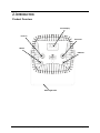
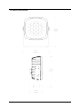
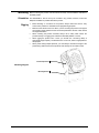
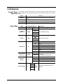
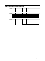
User Manual TABLE OF CONTENTS 1. Before You Begin ...........................................................................................................3 What Is Included ........................................................................................................................ 3 Unpacking Instructions ............................................................................................................... 3 Claims .............................................................................................................................................. 3 Text Conventions ....................................................................................................................... 3 Icons .......................................................................................................................................... 3 Disclaimer .................................................................................................................................. 3 Product at a Glance ................................................................................................................... 4 Safety Notes .............................................................................................................................. 4 2. Introduction ....................................................................................................................5 Product Overview....................................................................................................................... 5 Product Dimensions ................................................................................................................... 6 3. Setup ...............................................................................................................................7 AC Power .................................................................................................................................. 7 Power Linking ................................................................................................................................... 7 Mounting .................................................................................................................................... 8 Orientation ........................................................................................................................................ 8 Rigging ............................................................................................................................................. 8 4. Operation ........................................................................................................................9 Control Panel Operation ............................................................................................................. 9 Menu Map.................................................................................................................................. 9 Configuration (DMX) ................................................................................................................ 10 DMX Personalities and Starting Address ......................................................................................... 10 DMX Channel Assignments and Values ................................................................................... 11 3-CH ............................................................................................................................................... 11 4-CH ............................................................................................................................................... 11 5-CH ............................................................................................................................................... 11 DMX Channel Assignments and Values (cont.) ........................................................................ 12 9-CH ............................................................................................................................................... 12 Configuration (Standalone)....................................................................................................... 13 Automatic Mode .............................................................................................................................. 13 Static Color Mode............................................................................................................................ 13 Custom Static Color Mode ............................................................................................................... 13 Dimmer Adjustment ......................................................................................................................... 13 Touch Control Panel Lock................................................................................................................ 14 Master/Slave Mode ......................................................................................................................... 14 5. Technical Information ..................................................................................................15 Product Maintenance ............................................................................................................... 15 6. Technical Specifications ..............................................................................................16 Returns .................................................................................................................................... 17 Contact Us ............................................................................................................................... 17 Page 2 of 17 SlimPANEL™ TRI 24 IP User Manual (Rev. 4) 1. BEFORE YOU BEGIN What Is Included • • • SlimPANEL™ TRI 24 IP DMX In Adapter DMX Out Adapter • • • Power Cord Warranty Card Quick Reference Guide Unpacking Instructions Immediately upon receipt, carefully unpack the product and check the box to make sure you have received all the parts indicated above in good condition. Claims If the box or the contents (the product and included accessories) appear damaged from shipping, or show signs of mishandling, upon receipt notify the carrier immediately, not CHAUVET®. Failure to do so in a timely manner may invalidate your claim with the carrier. In addition, keep the container and all the packing material for inspection. For other issues such as missing components or parts, damage not related to shipping, or concealed damage, file a claim with CHAUVET® within 7 days of receiving the merchandise. Text Conventions Symbols Convention 1–512 50/60 Settings Menu > Settings <ENTER> ON Symbol Meaning A range of values A set of values of which only one can be chosen A menu option not to be modified A sequence of menu options to be followed A key to be pressed on the product’s control panel A value to be entered or selected Meaning Critical installation, configuration, or operation information. Failure to comply with this information may cause the product to not work, damage it, or cause harm to the operator. Important installation or configuration information. Failure to comply with this information may prevent the product from working properly. Useful information. Disclaimer The information and specifications contained in this document are subject to change without notice. CHAUVET® assumes no responsibility or liability for any errors or omissions that may appear in this manual. CHAUVET® reserves the right to update the existing document or to create a new document to correct any errors or omissions. You can download the latest version of this document from www.chauvetlighting.com. © Copyright 2013 CHAUVET®. All rights reserved. Electronically published by CHAUVET® in the United States of America. Author Date Editor Updated A. Diaz 6/18/12 S. Diaz 1/23/13 SlimPANEL™ TRI 24 IP User Manual (Rev. 4) Page 3 of 17 Product at a Glance Use on Dimmer Outdoor Use Sound Activated DMX Master/Slave Safety Notes Auto Programs Auto-ranging Power Supply Replaceable Fuse User Serviceable Duty Cycle Please read the following Safety Notes carefully before working with the product. The Notes include important safety information about installation, usage, and maintenance. • • • • • • • • • • • • • • • • • • • Page 4 of 17 Always connect the product to a GFI (ground fault interrupter) circuit to avoid the risk of electrocution. Always disconnect the product from the power source before cleaning. Avoid direct eye exposure to the light source while the product is on. Make sure the power cord is not crimped or damaged. Never disconnect the product from power cord by pulling or tugging on the cord. If mounting the product overhead, always secure to a fastening device using a safety cable. Make sure there are no flammable materials close to the product when operating. Do not touch the product’s housing when operating because it may be very hot. Always make sure that the voltage of the outlet to which you are connecting the product is within the range stated on the decal or rear panel of the product. The product is for indoor or outdoor use (IP65!). Do not submerge the product. Always install the product in a location with adequate ventilation, at least 20 in (50 cm) from adjacent surfaces. Be sure that no ventilation slots on the product’s housing are blocked. Never connect the product to a dimmer. Make sure to replace the fuse with another of the same type and rating. Never carry the product from the power cord or any moving part. Always use the hanging/mounting bracket or the handles. The maximum ambient temperature (Ta) is 104° F (40° C). Do not operate the product at higher temperatures. In the event of a serious operating problem, stop using the product immediately. Never try to repair the product. Repairs carried out by unskilled people can lead to damage or malfunction. Please contact the nearest authorized technical assistance center. Keep this User Manual for future consultation. If you sell the product to another user, be sure that they also receive this document. SlimPANEL™ TRI 24 IP User Manual (Rev. 4) 2. INTRODUCTION Product Overview Touch Display Power In Power Out DMX In DMX Out Mounting Bracket SlimPANEL™ TRI 24 IP User Manual (Rev. 4) Page 5 of 17 Product Dimensions Page 6 of 17 SlimPANEL™ TRI 24 IP User Manual (Rev. 4) 3. SETUP AC Power The SlimPANEL™ TRI 24 IP has an auto-ranging power supply and it can work with an input voltage range of 100–240 VAC, 50/60 Hz. To determine the product’s power requirements (circuit breaker, power outlet, and wiring), use the current value listed on the label affixed to the product’s back panel, or refer to the product’s specifications chart. The listed current rating indicates the product’s average current draw under normal conditions. Always connect the product to a protected circuit (circuit breaker or fuse). Make sure the product has an appropriate electrical ground to avoid the risk of electrocution or fire. Never connect the product to a rheostat (variable resistor) or dimmer circuit, even if the rheostat or dimmer channel serves only as a 0 to 100% switch. Power Linking The product provides a power linking option via the pigtails located on the back of the unit. You can daisy chain up to 6 units on 120 VAC or up to 12 units on 230 VAC. If you choose not to use the power linking feature, be sure to use the included screw on cap to prevent any water from getting into the power cords. The power linking information above corresponds to the North American version of the product ONLY! If using the product in other markets, you must consult with the local CHAUVET® distributor as power linking connectors and requirements may differ in your country or region. SlimPANEL™ TRI 24 IP User Manual (Rev. 4) Page 7 of 17 Mounting Before mounting the product, read and follow the safety recommendations indicated in the Safety Notes. Orientation The SlimPANEL™ TRI 24 IP may be mounted in any position; however, make sure adequate ventilation is provided around the product. Rigging • Before deciding on a location for the product, always make sure there is easy access to the product for maintenance and programming purposes. • Make sure that the structure onto which you are mounting the product can support the product’s weight. Please see the Technical Specifications section of this manual for weight information. • When mounting the product overhead, always use a safety cable. Mount the product securely to a rigging point, whether an elevated platform or a truss. • When rigging the product onto a truss, you should use a mounting clamp of appropriate weight capacity. The bracket has a 13 mm hole, which is appropriate for this purpose. • When power linking multiple products, you must always consider the length of the power linking cable and mount the products close enough for the cable to reach. Bracket Adjustment Mounting Diagram Mounting Bracket Page 8 of 17 SlimPANEL™ TRI 24 IP User Manual (Rev. 4) 4. OPERATION Control Panel Operation To access the control panel functions, use the four buttons located underneath the display. Please refer to the Product Overview to see the button locations on the control panel. Button <MENU> <UP> Menu Map Function Press to find an operation mode or to back out of the current menu option Press to scroll up the list of options or to find a higher value <DOWN> Press to scroll down the list of options or to find a lower value <ENTER> Press to activate a menu option or a selected value Mode DMX Address Programming Steps Description Addr Selects DMX starting address d__1-d512 3CH DMX Personalities 4CH PRES 5CH Selects DMX personality 9CH OFF Dimmer DIM1 DIM DIM2 Change dimmer speed DIM3 Static Color Touch Control Panel Lock Custom Color Mixing C-- PASS C1 Red C2 Green C3 Blue C4 Cyan C5 Magenta C6 Yellow C7 White ON Locks touch control panel Password is UP,DOWN,UP,DOWN,ENTER OFF U-- r-- Red g-- Green b-- Blue S-- Strobe rate P1 P2 Auto Programs P-- P3 P4 S__1S100 Auto program selection and speed selection P5 SlimPANEL™ TRI 24 IP User Manual (Rev. 4) Page 9 of 17 Configuration (DMX) DMX Personalities and Starting Address Set 1. 2. 3. the product in DMX mode to control with a DMX controller. Connect the product to a suitable power outlet. Turn the product on. Connect a DMX cable from the DMX output of the DMX controller to the DMX input socket on the product. The SlimPANEL™ TRI 24 IP has 4 DMX personalities, from a 3-channel mode for basic control to a 9-channel mode with more advanced control over the lights. The SlimPANEL™ TRI 24 IP uses up to 9 DMX channels in its 9-channel DMX mode, which defines the highest configurable address to 504. When selecting a starting DMX address, always consider the number of DMX channels the selected DMX mode uses. If you choose a starting address that is too high, you could restrict the access to some of the product’s channels. If you are not familiar with the DMX protocol, download the DMX Primer at www.chauvetlighting.com. To select the DMX personality, do the following: 1. Press <MENU> repeatedly until PERS shows on the display. 2. Use <UP> or <DOWN> to select 3CH, 4CH, 5CH or 9CH. 3. Press <ENTER> to choose your DMX personality when it appears on the display. To then choose your starting address: 1. Press <MENU> repeatedly until Addr shows on the display. 2. Use <UP> or <DOWN> to select the starting address. 4. Press <ENTER>. Page 10 of 17 SlimPANEL™ TRI 24 IP User Manual (Rev. 4) DMX Channel Assignments and Values 3-CH 4-CH 5-CH Channel Function Value Setting 1 Red 000 255 0–100% 2 Green 000 255 0–100% 3 Blue 000 255 0–100% Channel Function Value Setting 1 Dimmer 000 255 0–100% 2 Red 000 255 0–100% 3 4 Green Blue 000 255 0–100% 000 255 0–100% Channel Function Value Setting 1 Red 000 255 0–100% 2 Green 000 255 0–100% 3 4 Blue Dimmer 5 Strobe 000 255 0–100% 000 255 0–100% 000 010 No function SlimPANEL™ TRI 24 IP User Manual (Rev. 4) 011 255 Slow to fast Page 11 of 17 DMX Channel Assignments and Values (cont.) 9-CH Page 12 of 17 Channel Function Value Setting 1 Dimmer 000 255 0–100% 2 Red 000 255 0–100% 3 4 Green Blue 5 Color Macros 6 Strobe 7 Auto Programs 8 Auto Program Speed 9 Dimmer Curve 000 255 000 255 000 010 011 200 201 205 206 210 211 215 216 220 221 225 226 230 231 235 236 240 241 245 246 250 251 255 000 009 010 255 000 051 052 101 102 152 153 203 204 254 255 000 255 000 051 052 101 102 152 153 203 204 255 0–100% 0–100% No function Color Macros White 1: 3200K White 2: 3400K White 3: 4200K White 4: 4900K White 5: 5600K White 6: 5900K White 7: 6500K White 8: 7200K White 9: 8000K White 10: 8500K White 11: 10000K No function 0–100% (slow to fast) No function Auto Program 1 Auto Program 2 Auto Program 3 Auto Program 4 Auto Program 5 Slow to fast (when Ch. 7 is 052–255) Default speed Linear dimmer Nonlinear dimmer 1 Nonlinear dimmer 2 Nonlinear dimmer 3 SlimPANEL™ TRI 24 IP User Manual (Rev. 4) Configuration (Standalone) Set the product in one of the standalone modes to control without a DMX controller. 1. Connect the product to a suitable power outlet. 2. Turn the product on. Never connect a product that is operating in any standalone mode to a DMX string connected to a DMX controller. Products in standalone mode may transmit DMX signals that could interfere with the DMX signals from the controller. Automatic Mode Static Color Mode Custom Static Color Mode To enable the Automatic Mode, follow the instructions below: 1. Press <MENU> repeatedly until P-- shows on the display. 2. Press <ENTER>. 3. Use <UP> or <DOWN> to choose an auto program (P1-P5). 4. Press <ENTER> to adjust the speed of the program. 5. Use <UP> or <DOWN> to adjust the duration of each step of the automatic program from S__1 (fast) to S100 (slow). 6. Press <ENTER>. To enable the Static Color Mode, follow the instructions below: 1. Press <MENU> repeatedly until C-- shows on the display. 2. Press <ENTER>. 3. Use <UP> or <DOWN> to choose a color (C1-C7). 4. Press <ENTER>. To enable the Custom Static Color Mode, follow the instructions below: 1. Press <MENU> repeatedly until U-- shows on the display. 2. Press <ENTER> to choose between colors (r--, g--, b--). 3. Press <UP> or <DOWN> to choose the intensity of the color (000-100). 4. Repeat the steps to mix additional colors to create the color you need. 5. Press <ENTER>. You can also manually adjust the strobe rate. To do so, do the following: 1. Press <MENU> repeatedly until U-- shows on the display. 2. Press <ENTER> until S-- shows on the display. 3. Press <UP> or <DOWN> to choose the strobe rate (S 0-S 20). 4. Press <ENTER> once you have chosen your desired strobe rate. Dimmer Adjustment You can manually control the dimmer speed to suit any need. To set up your preferred dimmer speed, do the following: 1. Press <MENU> repeatedly until DIM shows on the display. 2. Press <ENTER>. 3. Use <UP> or <DOWN> to choose between the dimming types (OFF-DIM3). 4. Press <ENTER>. SlimPANEL™ TRI 24 IP User Manual (Rev. 4) Page 13 of 17 Touch Control Panel Lock To enable the touch panel lock, follow the instructions below: 1. Press <MENU> repeatedly until PASS shows on the display. 2. Press <ENTER>. 3. Press <UP> or <DOWN> until ON shows on the display to enable the touch panel lock. To disable the touch panel lock so you can resume functionality, follow the steps below: 1. Press <UP>, <DOWN>, <UP>, <DOWN>, <ENTER> to disable the touch panel lock. 2. Press <MENU> to move through the menus as normal. In situations where water may flow onto the touch display, use the Touch Panel Control Lock so that the water does not reset the product’s settings. Master/Slave Mode Page 14 of 17 The Master/Slave mode allows a single SlimPANEL™ TRI 24 IP unit (the “master”) to control the actions of one or more SlimPANEL™ TRI 24 IP units (the “slaves”) without the need of a DMX controller. The master unit will be set to operate in a standalone mode, while the slave units will be set to operate in Slave Mode. Once set and connected, the slave units will operate in unison with the master unit. Configure the units as indicated below. Slave units: 1. Press <MENU> repeatedly until Addr shows on the display. 2. Press <ENTER> to accept. 3. Set the DMX address to 001. 4. Connect the DMX input of the first slave unit to the DMX output of the master unit. 5. Connect the DMX input of the subsequent slave units to the DMX output of the previous slave unit. 6. Finish setting and connecting all the slave units. Master unit: 1. Set the master unit to operate in standalone mode. 2. Make the master unit the first unit in the daisy chain. • Configure all the slave units before connecting the master unit to the daisy chain. • Never connect a DMX controller to a DMX string configured for Master/Slave operation because the controller may interfere with the signals from the master unit. • Do not connect more than 31 slave units to the master unit. SlimPANEL™ TRI 24 IP User Manual (Rev. 4) 5. TECHNICAL INFORMATION Product Maintenance Dust build-up reduces light output performance and can cause overheating. This can lead to reduction of the light source’s life. To maintain optimum performance and minimize wear, you should clean your lighting products at least twice a month. However, use and environmental conditions contribute to increased cleaning frequency. To clean the product, follow the instructions below: • Unplug the product from power. • Wait until the product is cold. • Use a vacuum (or dry compressed air) and a soft brush to remove dust collected on the external surface/vents. • Clean all external optics and glass/transparent surfaces with a mild soap solution, ammonia-free glass cleaner, or isopropyl alcohol. • Apply the solution directly to a soft, lint free cotton cloth or a lens cleaning tissue. • Softly drag any dirt or grime to the outside of the external optics or glass/transparent surface. • Gently polish the external optics and glass/transparent surfaces until they are free of haze and lint. Always dry the external optics and glass/transparent surfaces carefully after cleaning them. SlimPANEL™ TRI 24 IP User Manual (Rev. 4) Page 15 of 17 6. TECHNICAL SPECIFICATIONS Dimensions and Weight Length Width Height Weight 10.5 in (268 mm) 11.9 in (301 mm) 5.3 in (134 mm) 13.8 lbs (6.2 kg) Note: Dimensions in inches rounded to the nearest decimal digit. Power Light Source Photo Optic Thermal DMX Ordering Page 16 of 17 Power Supply Type Range Voltage Selection Switching (internal) 100–240 V, 50/60 Hz Auto-ranging Parameter 120 V, 60 Hz 230 V, 50 Hz Consumption 137 W 146 W Operating 1.2 A 0.6 A Power linking current (units) 8 A (6 units) 8 A (12 units) Fuse F 2 A, 250 V F 2 A, 250 V Power I/O U.S./Worldwide UK/Europe Power input connector Proprietary Proprietary Power output connector Proprietary Proprietary Power Cord plug Edison (U.S.) Local plug Type Power Lifespan LED 3W 50,000 hours Color Quantity Current Tri-color 24 350 mA (x3) Parameter Illuminance @ 2 m 5,850 lux Beam angle 20º Field angle 34° Maximum External Temp. Minimum Startup Temp. Cooling System 113° F (45° C) -4° F (-20° C) Convection I/O Connectors Connector Type Channel Range 3-pin XLR Proprietary 3, 4, 5, 9 Product Name Item Code Item Number SlimPANEL™ TRI 24 IP 03030532 SLIMPANELTRI24IP SlimPANEL™ TRI 24 IP User Manual (Rev. 4) In case you need to return a product or request support: • • • If you live in the U.S., contact CHAUVET® World Headquarters (see below). If you live in the UK or Ireland, contact CHAUVET® Europe Ltd. (see below). If you live in any other country, DO NOT contact CHAUVET®. Instead, contact your distributor of record. See www.chauvetlighting.com for distributors outside the U.S., United Kingdom, or Ireland. If you live outside the U.S., United Kingdom, or Ireland, contact your distributor of record and follow their instructions on how to return CHAUVET® products to them. Visit our website for contact details. Returns Call the corresponding CHAUVET® Tech Support office and request a Return Merchandise Authorization (RMA) number before shipping the product. Be prepared to provide the model number, serial number, and a brief description of the cause for the return. You must send the merchandise prepaid, in its original box, and with its original packing and accessories. CHAUVET® will not issue call tags. Clearly label the package with the RMA number. CHAUVET® will refuse any product returned without an RMA number. Write the RMA number on a properly affixed label. DO NOT write the RMA number directly on the box. Before sending the product, clearly write the following information on a piece of paper and place it inside the box: • Your name • Your address • Your phone number • The RMA number • A brief description of the problem Be sure to pack the product properly. Any shipping damage resulting from inadequate packaging will be your responsibility. As a suggestion, proper UPS packing or doubleboxing is always a safe method to use. CHAUVET® reserves the right to use its own discretion to repair or replace returned product(s). Contact Us World Headquarters CHAUVET® General Information Address: 5200 NW 108th Avenue Sunrise, FL 33351 Voice: (954) 929-1115 Fax: (954) 929-5560 Toll free: (800) 762-1084 Technical Support Voice: (954) 929-1115 (Press 4) Fax: (954) 756-8015 Email: [email protected] World Wide Web www.chauvetlighting.com SlimPANEL™ TRI 24 IP User Manual (Rev. 4) United Kingdom & Ireland CHAUVET® Europe Ltd. General Information Address: Unit 1C Brookhill Road Industrial Estate Pinxton, Nottingham, UK NG16 6NT Voice: +44 (0)1773 511115 Fax: +44 (0)1773 511110 Technical Support Email: [email protected] World Wide Web www.chauvetlighting.co.uk Page 17 of 17