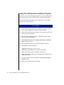
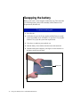
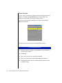
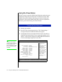
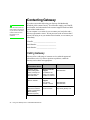
1
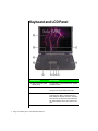
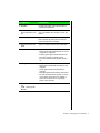
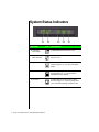
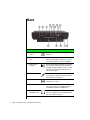
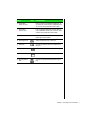
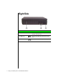
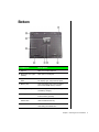
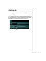
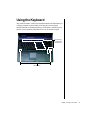
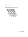
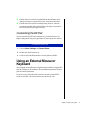
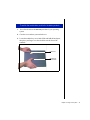
Contents
Chapter 1: Checking Out Your Notebook ............................... 1
Keyboard and LCD Panel....................................................................... 2
System Status Indicators ......................................................................... 4
Left side.................................................................................................... 5
Back ......................................................................................................... 6
Right Side ................................................................................................ 8
Bottom ..................................................................................................... 9
Chapter 2: Using Your System .............................................. 11
Connecting AC Power .......................................................................... 12
Starting Up............................................................................................. 13
LCD Panel ............................................................................................. 14
Using the Keyboard............................................................................... 15
Function keys.................................................................................. 16
Special keys .................................................................................... 18
Pad Lock keys................................................................................. 18
EZ Pad Pointing Device........................................................................ 20
Customizing the EZ Pad ................................................................ 21
Using an External Mouse or Keyboard ................................................ 21
Swapping Option Bay Modules............................................................ 22
Using the Audio..................................................................................... 25
Adjusting the volume..................................................................... 25
Making an Audio Recording ......................................................... 26
Using Disc Media (CD-ROM) ............................................................. 28
Playing an audio CD ...................................................................... 28
Removing or Replacing the Hard Disk Drive ...................................... 30
Using PC Cards ..................................................................................... 32
About CardBus Cards .................................................................... 33
USB (Universal Serial Bus) Ports......................................................... 34
Using Fast IR Ports................................................................................ 34
Using the Composite Video Ports......................................................... 35
Using the VidCap Demonstration Program .................................. 36
Chapter 3: Managing Power Consumption .......................... 39
Using the battery.................................................................................... 40
Battery learning software............................................................... 40
Contents
i
Thank you for purchasing this Factory Service
Manual CD/DVD from servicemanuals4u.com.
Please check out our eBay auctions for more great
deals on Factory Service Manuals:
servicemanuals4u
Battery status..................................................................................
Swapping the battery ............................................................................
Maximizing the battery life ..................................................................
Managing power ...................................................................................
Windows 98 ...................................................................................
Windows 95 and Windows NT ....................................................
Modifying the power button mode................................................
Using the BIOS Setup Utility...............................................................
Using the Power Menu ..................................................................
Status display .................................................................................
41
42
44
45
45
48
49
49
50
52
Appendix A: Solo Notebook Accessories ..............................53
Accessories ........................................................................................... 54
Appendix B: Contacting Gateway ..........................................55
Contacting Gateway.............................................................................. 56
Calling Gateway ............................................................................ 56
Index .......................................................................................57
ii
Using Your Gateway Solo™ 9100 Multimedia Notebook
Chapter 1:
Checking Out
Your Notebook
Keyboard and LCD Panel ....................................... 2
System Status Indicators ......................................... 4
Left side.................................................................... 5
Back.......................................................................... 6
Right Side................................................................. 8
Bottom...................................................................... 9
Keyboard and LCD Panel
2
Component
Description
A. XGA Color Liquid Crystal
Display (LCD)
Provides sharp, crisp resolution with backlit
anti-glare screen.
B. Power button
Press to turn power ON or OFF. Can also be
configured to Suspend/Resume mode.
C. Keyboard
Provides full functionality of a desktop computer keyboard. Many of these keys have
been assigned alternate functions, including
shortcut keys for Windows 95 and Windows
98, Status Display menus, and numeric keypad.
Using Your Gateway Solo™ 9100 Multimedia Notebook
Component
Description
D. Speakers
Provide high quality sound reproduction for
software and audio CDs.
E. CD-ROM drive/Diskette
drive combination module
The CD-ROM drive reads data CDs or audio
CDs. The diskette drive accepts 3.5-inch diskettes.
F. EZ Pad™ TouchPad
Controls the cursor movement on the screen.
Buttons below the pad function as left and
right mouse buttons for clicking.
G. Hard drive access cover
panel
Opens to reveal and remove hard disk drive.
H. Power LED
Indicates that the power status mode:
• Steady green light indicates power is on and
computer is in operation.
• Flashing green light indicates that the computer is in standby or suspend mode.
• No LED indicates that the system power is
off.
I. Battery LED
Indicates the battery status mode:
• Green light indicates that the battery is fully
charged.
• Yellow light indicates that the battery is
charging.
• Red light indicates that a battery malfunction.
• No LED indicates that the system is running
on the battery because the AC adapter is
either not connected or is not providing
power to the computer.
J. System status indicators
(LCM - Liquid Crystal
Module)
Indicates that the system status modes.
Chapter 1: Checking Out Your Notebook
3
System Status Indicators
Indicator
4
Icon
Description
A. Hard drive
access light
Indicates that the hard drive is in use.
B. CD-ROM/Diskette disk drive
Indicates that the CD-ROM or the diskette
drive is in use.
C. Caps lock
Indicates that the caps lock in on. When the
Caps lock light is on, you type in all capital
letters.
D. Pad lock
Indicates that the pad lock is on. When the
Pad lock light is on, you can access the
embedded numeric keypad.
E. Scroll lock
Indicates that the scroll lock is on. When
Scroll lock light is on, some programs allow
you to scroll through large volumes of text.
Using Your Gateway Solo™ 9100 Multimedia Notebook
Left side
Component
Icon
Description
A. Volume wheel
Adjusts built-in speaker volume, external
speaker, and headphone volume. Other port
volume levels are controlled by multimedia software.
B. PC Card slots
Accepts two Type II PC Cards or one Type II
Card.
C. Eject buttons
Ejects the PC Cards from the PC Card slots.
D. Speaker
Provides high quality sound reproduction for
software and audio CDs.
Chapter 1: Checking Out Your Notebook
5
Back
Port
6
Icon
Description
A. Parallel port
(LPT1)
Connect parallel device such as a printer to
this port.
B. Joystick/MIDI
port
Connect a game joystick or an electronic
MIDI musical instrument this port. The port
provides both MIDI In and Out capabilities.
C. Fast IR (Infrared) port
Sends infrared signals between the notebook
and a remote device that uses infrared (for
example, another computer, printer, or other
peripheral). Place infrared devices up to 3
feet (1 meter) apart.
D. Mic
Connect an external microphone to this port.
Connecting an external microphone will disable the built-in microphone.
E. Line in
Records from another computer, stereo
equipment, or a VCR.
F. Line out
Connect an amplified speaker to this port.
The Line out port is not capable of driving
unamplified speakers or headphones.
G. Speaker out/
Headphone jack
Connect external speakers or headphones to
this port. Supports small unamplified speakers. (1/8-inch/3.5-mm jack.)
Using Your Gateway Solo™ 9100 Multimedia Notebook
Port
Icon
Description
H. Composite
Video Out port
Lets you view your notebook’s display on a
TV screen by connecting the notebook to the
TV or VCR using a standard video cable.
I. Composite
Video In port
Lets you display NTSC/PAL format video on
your notebook’s screen from a VCR or video
camera using a standard video cable.
J. Reset switch
Restarts the notebook, if necessary. Insert a
paper clip to press switch.
K. Kensington lock
Attach Kensington lock to this port.
L. PS/2 port
Connect an external mouse or keyboard to
this port.
M. Serial port
Connect an optional serial device to this port.
N. VGA port
Connect a VGA monitor cable to this port.
O. Docking station
port
Connect an optional docking station to this
port.
Chapter 1: Checking Out Your Notebook
7
Right Side
Component
8
Icon
Description
A. Speaker
Provides high quality sound reproduction for
software and audio CDs.
B. USB ports
Plug optional USB serial devices into these
ports.
C. Power connector
Connect an AC power adapter to this port.
Using Your Gateway Solo™ 9100 Multimedia Notebook
Bottom
Component
Description
A. Flip foot
Flips out to tilt the notebook.
B. Back ports cover (open
position)
Flips open to reveal ports.
C. System identification
label
Provides product model number, serial number, display type, and processor speed.
D. Memory bay
Open the memory bay cover to install or
remove SO-DIMM memory modules.
E. Battery pack bay
Slide battery pack into bay for battery power
and battery charging.
F. Battery release latch
Slide the latch to release the battery pack
from the battery pack bay.
G. Combination module
release latch
Slide the latch to release the combination
drive module from the bay.
H. Combination module
Pull here to remove combination module
after sliding the release latch.
Chapter 1: Checking Out Your Notebook
9
10
Using Your Gateway Solo™ 9100 Multimedia Notebook
Chapter 2:
Using Your
System
Connecting AC Power........................................... 12
Starting Up............................................................. 13
LCD Panel.............................................................. 14
Using the Keyboard............................................... 15
EZ Pad Pointing Device ........................................ 20
Using an External Mouse or Keyboard ................ 21
Swapping Option Bay Modules............................ 22
Using the Audio..................................................... 25
Using Disc Media (CD-ROM).............................. 28
Removing or Replacing the Hard Disk Drive ...... 30
Using PC Cards ..................................................... 32
USB (Universal Serial Bus) Ports......................... 34
Using Fast IR Ports................................................ 34
Using the Composite Video Ports......................... 35
Connecting AC Power
Your notebook is powered by one of the longest-lasting batteries available
and was shipped to you charged, ready to use. You might, however, want to
use the AC adapter to provide a constant supply of power while you are
checking out some of the features.
Connecting the AC adapter
1. Connect the power cord to the AC adapter.
Caution!
Replace the power cord if it
becomes damaged. The
replacement cord must be
of the same type and
voltage rating as the
original cord.
Warning!
Do not attempt to
disassemble the AC
adapter. The AC adapter
has no user-replaceable or
user-serviceable parts
inside. The AC adapter has
dangerous voltages that
can cause serious personal
injury or death. Contact
Gateway about returning
defective AC adapters.
2. Plug the AC adapter into your notebook’s power connector.
3. Plug the power cord into an electrical outlet.
12
Using Your Gateway Solo™ 9100 Multimedia Notebook
Starting Up
Slide the latch on the front face of your notebook to the right to release the
cover and open up your notebook. To turn on your notebook, press the
power button, located in the upper left corner on the notebook surface, close
to the left LCD hinge.
The power button on your system is preset in On/Off mode. However, you
can set it to function either in On/Off or Suspend/Resume mode using the
setup screens (see “Using the BIOS Setup Utility” on page 49).
Power button
Chapter 2: Using Your System
13
LCD Panel
Note:
Your notebook features a color LCD XGA panel providing sharp, crisp
resolution and up to 256K (18 bits per pixel) color depth.
This system ships with the
“Auto dim with battery”
feature enabled. Auto dim
cuts LCD power 50% when
your notebook is operating
on battery power.
Tilt your notebook’s entire cover forward or backward to adjust the viewing
angle. Press the FN key together with the up arrow and down arrow keys to
control display brightness.
Some screens may have a small number of colored dots. This is normal and
does not affect the overall screen image.
14
Using Your Gateway Solo™ 9100 Multimedia Notebook
Using the Keyboard
Your notebook features a full-size keyboard that has the full functionality of
a desktop computer keyboard. Many of the keys have been assigned
alternate functions, including shortcut keys for Windows, function keys for
specific system operations, and pad lock keys for the numeric keypad.
Function keys
for function key
combinations
Function Key
Chapter 2: Using Your System
15
Function keys
Press the FN key together with one of the following keys (with blue letters)
to get these “on-the-fly” functions:
Key
Combination
Description
+
Displays the power status in the upper left corner of the
Windows desktop. Press the key combination again to
make the display disappear.
Toggles between the LCD display, external monitor, both
displays at the same time, or TV display (NTSC or PAL
format). See “LCD Panel” on Page 14.
Windows 95: LCD and Hard Drive shut off. Pressing any
key will bring them back within a few seconds.
Windows 98: System goes to sleep. Pressing the power
button will bring the system out of sleep mode.
Makes temporary changes to the power management
(PM) mode settings by toggling the setting options:
• PM ON enables power management with AC or battery
power.
• PM DC enables power management when the notebook is using battery power only.
• PM OFF disables power management.
The selected option is not saved when the system is
turned off. The power management settings selected in
the BIOS setup program take effect when the system is
restarted.
16
Using Your Gateway Solo™ 9100 Multimedia Notebook
Key
Combination
Description
+
Makes changes to the video source (VIDEOSRC)
settings by toggling the settings from:
DVD, select if using your DVD drive (optional)
TV IN, select if using the Composite Video In port
PCMCIA, select if using a zoomed video card in PCMCIA slot
DISABLED
After about 30 seconds, the display disappears.
Enables the Pad Lock function so you can use the
numeric keypad.
The Pad Lock icon
stays lit while this function is
enabled. Press the key combination again to make the
display disappear.
In some programs you can scroll through large volumes
of text.
The Scroll Lock icon
is enabled.
stays lit as long as this function
In some programs this key combination pauses the display when text is scrolling quickly. Press any key to continue the text flow.
In some programs this key combination breaks text
scrolling in a DOS screen.
Increases LCD brightness and displays the brightness
meter for the Popup Status Display reflecting the
changes. Use the FN+F2 key combination to make the
display disappear
Chapter 2: Using Your System
17
Key
Combination
Description
+
Decreases LCD brightness and displays the brightness
meter for the Popup Status Display reflecting the
changes. Use the FN+F2 key combination to make the
display disappear.
Special keys
The following keys help you use shortcuts when working with some
software:
Key
Description
Use this key to display the Windows Start menu.
Use this key to provide quick access to shortcut menus
and help assistants in Windows.
18
Using Your Gateway Solo™ 9100 Multimedia Notebook
Pad Lock keys
Press FN+F9 (PAD LOCK) keys to activate the keypad. The keypad section of
the keyboard functions as a numeric keypad. Press FN+F9 to bring the
keyboard back into standard mode.
Chapter 2: Using Your System
19
EZ Pad Pointing Device
Like a mouse, the EZ Pad touch pad pointing device controls the
movements of the cursor on the screen. Press a finger against the pad, then
slide it in the direction that you want the cursor to move. Use the buttons or
tap on the pad to select something.
EZ pad
Touch pad buttons
When you first start your system, the Information about your Touchpad
displays. Select Tell me more for detailed information about features and
how to customize the EZ Pad.
With the EZ Pad you have two choices for each operation:
To click:
♦
♦
Position the cursor on the item and press the left button once
Position the cursor on the item and tap on the pad once.
-ORTo double-click:
♦
♦
Position the cursor on the item and press the left button twice
Position the cursor on the item and tap on the pad twice.
-ORTo drag and drop:
20
Using Your Gateway Solo™ 9100 Multimedia Notebook
♦
Position the cursor on the item and hold down the left button while
sliding your finger to reposition the cursor, then release the button
♦
Position the cursor on the item and tap on the pad twice. After the
second tap, hold and slide (without lifting your finger) to reposition
the cursor, then lift your finger to release.
Customizing the EZ Pad
You can customize the EZ Pad to work the way you want when you set
button configuration, drag, and edge motion or cursor speed, rate, and size.
To customize the EZ Pad
1. Click on Start, Settings and Control Panel.
2. Double-click on the mouse icon.
3. Click on each of the different tabs to see the options available.
Using an External Mouse or
Keyboard
You can attach an external mouse or keyboard to the notebook using the PS/2
port, the USB port, or the serial port. The optional docking stations also have
ports for external connections.
It is not necessary to shut down the system to connect an external PS/2
mouse or keyboard. Just connect it to the port and start to work.
Chapter 2: Using Your System
21
Swapping Option Bay Modules
Your notebook features a modular option bay that accepts the modular CDROM/Diskette disk combination drive or an additional battery.
The CD-ROM/Diskette disk combination drive can be replaced by a second
battery module in the modular option bay. Each time you switch them,
however, you must restart your system.
Modular option bay
22
Using Your Gateway Solo™ 9100 Multimedia Notebook
To switch the combination module for the battery module
1. Save all work and use the Shut Down procedure in your operating
system.
2. Close the cover and turn your notebook over.
3. Locate the modular bay access latch. Slide and hold the latch open,
then place your fingers over the raised bar near the front of the
notebook.
Raised bar
Modular bay
access latch
Chapter 2: Using Your System
23
4. Pull the CD-ROM/Diskette disk combination drive module straight
out and away from your notebook, and release the latch.
5. Install the correct faceplate on the second battery. For details, see the
instructions that come with the second battery.
Note:
Anytime you replace a
module you must restart
your system for the module
to work. The restart has to
occur after the module is
correctly seated.
6. Turn the battery module over. (Your notebook was turned over, so the
module being installed must be turned over as well.)
7. Firmly push the module straight into the bay until the latch “clicks”
into place. If you don’t hear the “click” try it firmly again, making sure
it “clicks.”
8. Restart your system.
24
Using Your Gateway Solo™ 9100 Multimedia Notebook
Using the Audio
Your system comes with flexibility for using audio. You can record audio
for presentations, attach voice messages to your e-mail, listen to audio CDs,
and use it for many other multimedia applications. This section tells you
more about using audio.
Adjusting the volume
There are numerous ways to adjust audio input and output on your Solo
notebook computer. The Volume Control Wheel controls the Speaker Out
port and the internal system speakers. The volume level for other ports is
controlled by the multimedia software.
To adjust playback and recording volume levels
1. Click Start, Settings and Control Panel. Double click the Multimedia icon.
The Multimedia Properties dialog box opens.
2. Click the Audio tab.
3. Set the Playback and Recording levels to your preference.
To “quick-adjust” volume controls
1. Double-click the Speaker icon (bottom right-hand corner).
A Volume Control dialog box opens, containing volume and balance
controls for master volume control, CD audio, wave, synthesizer, line,
microphone and 3D Enhanced settings.
2. Slide the various volume and balance controls to suit your listening
requirements.
Chapter 2: Using Your System
25
Making an Audio Recording
Note:
To make an audio recording, use the built-in microphone or connect an
external microphone to the Mic port.
Connecting an external
microphone will disable the
built-in microphone.
To make an audio recording
1. Click Start, Programs, Accessories, Multimedia, then Sound Recorder. The
Sound Recorder opens.
2. Click Edit, then Audio Properties, then set or check record volume levels.
3. Click OK.
4. Click the ● (Record) button. Recording starts.
5. When you are finished recording, the ■ (Stop) button. Recording
stops.
6. Click File, then Save As.
7. Name the recording.
8. Click Save.The recording is saved.
To play back a recording in Media Player
1. Click Start, Programs, Accessories, Multimedia, then Media Player. The
Media Player opens.
26
Using Your Gateway Solo™ 9100 Multimedia Notebook
2. Click File, then Open. The Open dialog box appears.
3. Select the file to play back.
4. Click Open.
5. To play the file, click the
(Play) button.
6. To stop the file, click the ■ (Stop) button.
Chapter 2: Using Your System
27
Using Disc Media (CD-ROM)
Your system has a CD-ROM drive. This section describes some of the ways
to use CD-ROM media.
To insert a CD
1. Press the Eject button. The CD drive tray opens.
2. Insert the CD. Press down carefully on the CD to ensure that it snaps
under the clips that hold the CD in the tray.
Be sure to place the CD in the tray so that the label side is facing up. If
the disc has two playable sides, place the disc so that the name of the
side you want to play (A or B) is facing up.
3. Press the Eject button. The tray closes.
To access information on the CD drive
1. Double-click the My Computer icon. The My Computer window opens.
2. Double-click the CD-ROM drive icon.
Playing an audio CD
The CD-ROM accepts standard CD data discs and music CDs. You can
play and control an audio CD using the CD Player application in Windows.
To play an audio CD
1. Insert an audio CD. After a few seconds, the CD-ROM starts playing
automatically.
2. Click the CD Player taskbar button to use the CD Player software.
28
Using Your Gateway Solo™ 9100 Multimedia Notebook
- OR If the CD did not auto-start, then click Start, Programs, Accessories,
Multimedia, and CD Player to start the CD Player software.
3. Slide the mouse pointer slowly over the control buttons on the CD
Player software to get familiar with each button function.
4. You can change music tracks, view playing times, control the volume,
set preferences, define a play list and even set the system to
continuous or random play using this dialog box.
5. Control audio play as desired.
Chapter 2: Using Your System
29
Removing or Replacing the Hard
Disk Drive
You can remove your notebook's hard disk drive (HDD) for replacement or
to switch between optional additional hard drives.
To remove and replace the hard disk drive
1. Save all work.
2. Use your operating system’s shut down procedure to turn your
notebook completely off.
3. Close the LCD lid.
4. Disconnect the AC power and turn your notebook over.
5. Locate the modular bay access latch. Slide and hold the latch open and
remove the combination CD-ROM/diskette drive module from the
modular option bay.
Modular option bay latch
6. Open the flap door next to the modular option bay (notebook shown
with bottom up).
30
Using Your Gateway Solo™ 9100 Multimedia Notebook
Flap door
Hard drive
7. Grasp the black flap and pull the hard disk drive straight out from the
notebook.
Caution!
Do not force the hard drive.
Slide the new hard drive firmly into your notebook and close the flap door.
8.
9. Reinstall the CD-ROM/diskette combination drive module and AC
connections.
Chapter 2: Using Your System
31
Using PC Cards
Your notebook’s PC Card slots (also known as PCMCIA card slots) are
located behind the PC Card doors. These slots accept PC Card 16, PC Card
32 (CardBus), or Zoomed Video cards.
Your notebook is configured to automatically accept most PC Cards. If you
ordered your notebook with a modem, then the modem drivers are already
installed.
You do not need to restart your notebook when changing most cards
because your notebook supports “hot-swapping.” This means that you can
usually insert a PC Card, and the system recognizes it without shutting
down the notebook. If your PC Card does not work when hot-swapping,
refer to the PC Card manufacturer’s documentation for further information.
To insert a PC Card
Note:
If you are using a Type III
PC Card or Zoomed Video
card, it must be inserted
into the bottom slot.
1. Insert the PC Card with the label face up.
2. Slide the card firmly into the PC Card slot. When the card is installed
correctly, the computer emits a two-toned beep.
3. Follow the Windows Setup Wizard installation steps the first time you
insert a PC Card. Operate the device as recommended in the PC Card
manufacturer’s manual.
To remove a PC Card
1. Click the PC Card icon in the taskbar.
2. Click the card that you want remove.
3. Click Stop. A screen appears stating that you may safely remove the
device.
4. Click OK.
5. Press the PC Card eject button, located to the left of the PC Card slot,
to release the eject button.
32
Using Your Gateway Solo™ 9100 Multimedia Notebook
6. Press the PC Card eject button a second time to eject the PC Card.
7. Press the PC Card eject button to reset back into the notebook.
About CardBus Cards
The relatively new 32-bit CardBus technology (sometimes referred to as
“PC Card 32 cards”) supports DMA and bus mastering technologies that
are useful in performance-intensive applications like full-motion video,
high speed network connections, full-motion video capture and display, and
high performance peripheral interfaces.
While not many 32-bit CardBus cards are on the market yet, you can use
them interchangeably with 16-bit cards in your notebook. However, please
note that some Solo docking solutions do not support CardBus. CardBus
cards function only in your notebook’s PC Card slots.
Caution!
Be sure to wait for the “Safe
to remove” message before
you remove the CardBus
card, or you may crash your
system and lose all your
work.
Chapter 2: Using Your System
33
USB (Universal Serial Bus) Ports
USB is a new type of serial interface that serves as a single port alternative
to connecting devices that traditionally have required their own specific
ports such as mice, joysticks, keyboards, scanners, video conferencing
cameras, and speakers.
To use, connect the USB-compatible peripheral in the USB port. The USB
automatically installs and configures the necessary drivers and the system
resources.
Using Fast IR Ports
The IR (infrared) port uses infrared technology to send and receive signals
between the notebook and a remote device equipped with an IR port. A
variety of desktop computers, printers, and other peripherals are IRequipped. Use the manufacturer’s documentation to set up a remote IR
device.
Your notebook shipped with the IR port enabled. If you do not use the IR
port and need to make more resources (IRQs) available for other commonly
used devices, the IR port can be disabled. See Help on enabling/disabling
the IR port for more information.
34
Using Your Gateway Solo™ 9100 Multimedia Notebook
Using the Composite Video
Ports
The Composite Video Out port allows you to view your notebook’s display on a TV
screen by connecting the notebook to the TV or VCR using a standard video cable.
The Composite Video In port allows you to display video on your notebook’s
screen from a VCR or video camera using a standard video cable.
Note:
In addition to the hardware
connections necessary to
perform the functions
described in this section,
you also need to have a
video display program
installed.
To connect your notebook to a TV:
1. Connect one end of a standard video cable to the Composite Video
Out port on the notebook.
2. Connect the other end of the cable to the Video In connector on your
television or VCR.
3. Use the key combination FN+F3 to switch to Composite Video Out.
4. Reset your display setting to 640 x 480 resolution with large text fonts
for best viewing.
The Composite Video In
port lets you capture still
frames or motion video
from a VCR or video
camera on your notebook.
Windows drivers for use
with video capture software
programs are supplied with
your notebook.
To connect a VCR/Camera to your notebook
1. Connect one end of a standard video cable to the Composite Video In
port on the notebook.
2. Connect the other end of the cable to the Video Out connector on your
VCR or camera.
3. Use the key combination FN+F7 to select the TV IN video source.
Chapter 2: Using Your System
35
Using the VidCap Demonstration Program
VidCap is a video capture utility program that lets you display and capture
video (single frame or video stream) from the Composite Video In port.
You cannot edit video using VidCap. You can purchase a video editing
package from a software retailer.
To use VidCap:
1. Connect the Video Out port of your external source, such as a video
camera, to the Composite Video In port on your notebook.
2. Connect the Audio Out port, if available, of your external source to the
Line In port on your notebook.
3. Press FN+F7 until TV IN appears in the VIDEOSRC window in the
upper left corner of your screen.
4. Click the Start button, then click Programs, Video Capture, and Microsoft
VidCap. The program starts.
5. Play your external video source. Adjust the display if necessary.
6. Click Capture to view menu options:
• Single Frame captures one frame of video.
• Frames lets you manually click on specific video frames.
• Video automatically captures continuous video frames.
• Palette automatically captures the color palette from continuous and
single video frames.
7. To capture continuous frames, click Video. The Capture Video Sequence
dialog box opens.
8. When you’ve made all selections, click OK.
36
Using Your Gateway Solo™ 9100 Multimedia Notebook
9. The first time you use VidCap, the Set Capture File dialog box opens. Set
the path you want the file to be saved to, name the file, then click Open.
The default file name is always the last name specified. Select Set
Capture File from the File menu and change the file name before you
capture the video to avoid overwriting a previous video capture.
10. The first time you use VidCap, the Set File Size dialog box opens.
Set the amount of hard disk drive space you want the capture file to
use, then click OK. A window opens asking if you want to begin
capturing.
You can set the your file size equal to the amount of free disk space.
However, we do not recommend that you use the total amount of free
space. If you do, you will have to either delete your capture or other
existing data to regain free space on the hard drive for other
applications.
11. Click OK to begin capturing frames.
12. Right click anywhere in the VidCap window to stop capturing frames.
Chapter 2: Using Your System
37
38
Using Your Gateway Solo™ 9100 Multimedia Notebook
Chapter 3:
Managing
Power
Consumption
Using the battery.................................................... 40
Swapping the battery ............................................. 42
Maximizing the battery life................................... 44
Managing power.................................................... 45
Using the BIOS Setup Utility................................ 49
Using the battery
The battery must be installed in the notebook and connected to an AC
power source to charge completely. The battery will charge if your
notebook is operating as long as the AC adapter is properly connected. The
notebook can run on a fully charged battery for about 3 to 4 hours of
normal use before the battery needs recharging.
Battery learning software
About once a year you will need to run the Battery Learning Software
to recalibrate the battery gauge. The learning cycle increases the battery
gauge accuracy. Gauge accuracy changes over time.
Because the learning cycle can take as long as 16 hours per battery, we
suggest that you start the Learning Cycle program and run it overnight.
To perform a learning cycle on the battery pack
Note:
Removing the battery or
disconnecting the AC
power interrupts the
learning cycle. If the
learning cycle is
interrupted, it must be
restarted from the
beginning to properly
condition the battery.
40
1. Insert the battery into the battery bay.
2. Plug the AC adapter into the notebook and an AC outlet.
3. Insert the Battery Learning Cycle diskette in the A:\ drive.
4. Start up your notebook. The Learning Cycle software starts.
Follow the onscreen directions for the battery learning software.
Using Your Gateway Solo™ 9100 Multimedia Notebook
Battery status
You can check the battery status several ways.
♦
Position the cursor over the power cord (AC) or battery icon in the
lower right corner of the task bar. A battery status screen appears.
Moving the cursor anywhere on the display causes the screen to
disappear.
-OR-
♦
Click twice on the power cord or battery icon in the lower right corner
of the task bar. A more detailed battery status screen will appear. Click
on the X in the upper right corner of the screen to close it.
-OR-
♦
Click on Start, Settings and Control Panel. Double click on the Power
Management icon. You can view the battery status and set power
preferences from this screen, which stay in effect until they are
changed in Windows.
-OR-
♦
Press the FN key together with the F2 (Status) key. The power status
display appears in the upper left corner of the display. This display
monitors battery status and power management selection. BAT1
monitors the status of the battery pack in the battery bay. Press the FN
and the F2 (Status) keys again to make the display disappear.
When the battery level gets low:
♦
♦
♦
The system emits three beeps
The battery icon in the lower right of the task bar has a red “X” over it
The Low Battery screen appears, advising you to change your battery
or switch to AC power immediately to prevent losing your work.
Connect the AC adapter to the notebook to recharge the battery.
Chapter 3: Managing Power Consumption
41
Swapping the battery
Battery packs can be “warm-swapped” in the battery bay. This means that
you can change battery packs while in Standby mode (Windows 98) or
Suspend mode (Windows 95).
To replace the battery pack
1. Save all work.
2. In Windows 98, press the FN key together with the F4 key to put the
system into standby mode. In Windows 95, press the FN key together
with the F5 key to put the system into suspend mode.
3. Close the cover and turn your notebook over.
4. Slide the battery release latch toward the center of the notebook.
5. Hold the latch in place and place your fingers over the raised bar on
the battery pack next to the latch.
Battery latch
42
Using Your Gateway Solo™ 9100 Multimedia Notebook
6. Slide the battery pack straight out and away from your notebook. You
may now release the battery release latch.
7. Slide a battery pack (bottom side up) straight into the battery bay until
it “snaps” into place.
8. Turn the notebook right side up and open the cover.
9. Press the power button to resume power to the system.
Chapter 3: Managing Power Consumption
43
Maximizing the battery life
You can extend the battery life by following these practices:
♦
♦
Dim the display brightness as low as is comfortable.
♦
Remove PC Cards when not in use. Some PC Cards use battery power
even when they are not in use. Check the PC Card manufacturer’s
documentation to find out if the card uses power when not in use.
♦
Keep the battery pack in the computer when using AC power to
continuously charge the battery.
♦
Minimize using CD-ROM drive. The CD-ROM drive uses
considerable battery power.
♦
Adjust the Power management settings most effectively for the way
you use your notebook.
Close the LCD lid when not in use. The LCD display turns off until
the lid is opened.
See “Managing power” on Page 45 for more information about changing
the power management settings in Windows 98.
See “Using the Power Menu” on Page 50 for more information about
accessing the Power menu settings in the BIOS setup program for Windows
95 and Windows NT.
44
Using Your Gateway Solo™ 9100 Multimedia Notebook
Managing power
A battery-powered session for your notebook is affected by many things
such as using screen savers rather than the suspend function, or playing
music CD-ROMs while using a word processor. If no AC power outlet is
available, you want to make the battery-powered session last as long as
possible.
Power management is handled differently in Windows 98 than in Windows
95 and Windows NT. The following two sections address these differences.
Refer to the section that applies to your operating system.
Windows 98
To modify your power management settings in Windows 98, you do not
need to open the BIOS setup program. This is only necessary if you want to
change the power button setting. Instead, Windows 98 includes a Power
Management Properties dialog box.
To use the Power Management Properties dialog box
1. Click the Start button, Settings, and Control Panel.
2. In the Control Panel window, double-click the Power Management icon.
3. Click the appropriate tab to view and modify settings.
Chapter 3: Managing Power Consumption
45
Power schemes
A power scheme is a named set of properties selected in the Power Schemes
window. For example, the Portables/Laptop power scheme changes the
settings to maximize battery life in your notebook system.
You can select one of three pre-defined power schemes from the Power
schemes drop-down list.
You can also create your own power scheme and add it to the list.
To create a power scheme
1. In the Power Schemes window, set the properties as you want them to
be in your power scheme.
2. Click Save As.
3. Type a name for your power scheme and click OK.
4. Select your power scheme from the Power scheme drop-down list.
5. Click OK at the bottom of the Power Management Properties window
to apply the change.
46
Using Your Gateway Solo™ 9100 Multimedia Notebook
Alarm settings
Even though there are several ways to keep tabs on your battery power,
alarms letting you know that you might be about to lose battery power are
useful.
The Alarms window lets you turn off and turn on the alarms, set the point at
which your notebook alerts you that your battery is running low, and select
the notification method.
Chapter 3: Managing Power Consumption
47
Using Standby mode in Windows 98
Windows 98 uses Standby mode. When in Standby mode, your notebook
enters a sleep state. Cutting off power to most devices except memory.
The following table shows how to change the system modes in
Windows 98.
If your
notebook
is...
...and you
want to...
...then do this:
Off
Start up
Press the power button
On
Standby
Click Start, Shut Down, Standby, then
click OK.
- OR Press FN+F4
In Standby
mode
Resume
power
Press the power button briefly
On
Shut down
Click Start, Shut Down, click Shut Down
again, then click OK.
Windows 95 and Windows NT
To modify your power management settings in Windows 95 and
Windows NT, you need to go into the BIOS program to change the power
management settings. See “Using the Power Menu” on Page 50 for more
information on these settings and how to modify them.
Using Suspend mode in Windows 95 and Windows NT
Windows 95 and Windows NT use Suspend mode. When in Suspend
mode, your notebook enters a sleep state according to the power
management settings. Suspend mode cuts off power from most devices
except memory.
48
Using Your Gateway Solo™ 9100 Multimedia Notebook
The following table shows how to change the system modes in Windows 95
and Windows NT.
If your
notebook
is...
...and you
want to...
then do this:
Off
Start up
Press the power button
On
Suspend
Click Start, Suspend
In Suspend
mode
Resume
power
Press the power button briefly
On
Shut down
Click Start, Shut Down, Shut down the
computer, then click Yes.
Modifying the power button mode
You can change the power button mode in the BIOS setup program from
On/Off to Standby/Resume. See “Using the Power Menu” on Page 50 for
more information about accessing the BIOS Power menu settings to change
the power button mode.
Using the BIOS Setup Utility
The computer’s BIOS has a built-in program that lets you set many basic
system characteristics. These settings are stored and saved even when the
power is off. This section contains information about this setup utility and is
intended to serve as a guide so that you can make changes to your system
BIOS when necessary.
The screen example that you see in this chapter is similar to what you see on
your LCD. However, you may have a system with a newer BIOS version
than the one described in this manual. If there are differences, follow the
Item Specific Help box in the right-hand column of the BIOS Setup menu.
Chapter 3: Managing Power Consumption
49
Using the Power Menu
The Power menu is a part of the BIOS Setup Utility that contains the power
management settings and system timeouts. Use the Power menu to make
changes to the system to improve the battery-powered session time and
performance. The rest of the BIOS Setup Utility screens are explained in
Maintaining and Troubleshooting Your Solo Notebook.
To access the Power Setup menu
1. Start-up your notebook.
2. Press the F2 key when prompted to do so. The “Entering Setup...”
message briefly shows and then the Main menu appears.
3. Use the right arrow key to navigate to the Power menu. Use the keys
identified at the bottom of the screen to navigate through the various
options. An Item Specific Help bar providing additional information
is also located along the right side of each menu.
PhoenixBIOS Setup Utility
Note:
The Power menu screen
shown may differ somewhat
from that shown here. If
there are differences, follow
the on-screen instructions
and helps.
Main
Advanced
Security
Exit
Item Specific
Help
Power Button Mode: [On/Off]
PM Control: [Battery]
Power Savings: [Maximum Battery Life]
Standby timeout:
Suspend timeout:
Hard disk timeout:
Video timeout:
Audio timeout:
Battery Low suspend:
Resume On Modem Ring:
Resume On Time:
Resume Time:
Auto Dim With Battery
Only:
Cooling Control:
2 Minutes
10 Minutes
2 Minutes
4 Minutes
2 Minutes
[On]
[Off]
[Off]
[00:00:00]
[On]
[Silence]
F1 Help
↑↓ Select Item
ESC Exits
←→ Select Menu
Exit
50
Power
Using Your Gateway Solo™ 9100 Multimedia Notebook
Select Power button
functionality.
Suspend/Resume:
Button functions as
“Suspend/Resume”
switch. If you want
to turn the power
off in this mode,
you must press and
hold power button
over 2 seconds.
On/Off: Button
functions as “On/
Off” switch.
-/+ Change Values
F9
Enter Select > Sub-Menu
Setup Default
F10 Save and
The settings you are most likely to change include:
♦
Power button mode; which sets power switch functionality. When you
press the power button, the system can be set to either Shut Down or
Suspend. Press the spacebar to select On/Off or Suspend/Resume.
♦
PM Control, which provide preset or customized power management.
Setting this option to Maximum Performance provides the notebook with
the best system performance. Setting this option to Maximum Battery
Life provides your notebook the best battery performance. Setting this
option to Customize allows you to manually set the Standby, Suspend,
Hard disk, and Video timeouts. Press the spacebar to choose between
options.
♦
Auto dim with battery, which decreases when this feature is enabled, the
LCD brightness automatically decreases by 50 percent when using
battery power only. Press the spacebar to select On or Off.
Chapter 3: Managing Power Consumption
51
Status display
Note:
Changes in power
management levels are
temporary and do not affect
the power settings in the
BIOS setup screens. The
changes are only in effect
until the system is rebooted
or powered off, then the
BIOS power settings are
restored.
The Status menu display feature is supported by the VGA controller chip.
The displays appear in the upper left corner of the display and disappear
after about 30 seconds.
♦
Power status display: appears when you press the FN key together
with the F2 (Status) or the F6 (PM) key. It shows current battery status
and Pwr Mgmt (power management) level. The display is updated
when you change any function choice.
♦
Battery status: appears in the top two lines. The top line reflects the
status of the primary battery pack. If the battery level is low, a warning
icon will appear.
The power management levels appear in the third and fourth lines. You can
toggle between levels by pressing the FN key together with the F6 (Pwr
Mgmt) key.
AC power status is monitored on the fifth line.
♦
52
The Brightness meter: shows the brightness level for the LCD panel.
Press the FN key and tap the Up Arrow or Down Arrow key to
increase or decrease the brightness level in single increments.
Using Your Gateway Solo™ 9100 Multimedia Notebook
Appendix A:
Solo
Notebook
Accessories
Accessories
Note:
For more information on
this or other Gateway
accessories for your
notebook, call (800) 8462000.
We offer many accessories that can help you make the most of using your
Solo notebook. Visit our website at www.gateway.com or call our Add-Ons
group to help you find products that will best fit your needs.
Accessories such as memory modules, external keyboards, speakers,
carrying cases, printers, tape backup units, hard drives, modems, network
cards, software, and uninterruptable power supplies (UPS) are available.
Other accessories we offer include:
♦
The Docking station, a full-featured expansion unit designed for
mobile users who require the modularity and functionality of a
desktop system. The docking station’s key features include two dual
expansion slots (PCI or ISA), a 3.5" hard drive expansion bay, a 5.25"
or 3.25" device expansion bay, two PC Card slots, built-in stereo
speakers, and a removable monitor stand.
Other features are the MIDI/game port and two PS/2 ports that let you
attach peripheral devices such as an external keyboard, mouse, or
joystick to the docking station. Once you connect the peripherals, you
can leave them attached for the next time you need them.
54
♦
The Mini-docking station, which enhances the capabilities of your
Solo notebook by providing a one-step connection to external devices
such as a monitor, keyboard, mouse, printer, serial device, joystick,
external power, speakers, and microphone. This docking station
provides additional PC Card slots for expanded functionality when
using network cards, SCSI adapters, and modems.
♦
An extra battery pack for when you’re on the road and have no place
to plug into AC power.
♦
The battery charger, which can be used to charge your battery packs.
It takes approximately two to three hours to charge a fully discharged
battery. This battery charger has two LEDs to indicate battery charge
status.
♦
The automobile/airplane adapter, which provides a safe and easy
way to plug any Solo notebook into the industry standard EmPower inseat power receptacles now available on major airlines, or into any
available cigarette lighter in a car, boat, or RV.
Using Your Gateway Solo™ 9100 Multimedia Notebook
Appendix B:
Contacting
Gateway
Contacting Gateway .............................................. 56
Calling Gateway............................................. 56
Contacting Gateway
Note:
Your Client ID number and
order number can be found
on your invoice. The serial
number can be found on
the bottom of your
notebook.
If you have any trouble while using your Gateway Solo Multimedia
Notebook, please contact Gateway. You will need to supply your Client ID,
serial number, and order number to the customer support technicians. Make
a note of these numbers here.
If your computer is ever stolen, be sure to contact your local police and a
Gateway representative at once. We can put a note on the account so that if
anyone calls trying to use your notebook serial number, we can contact you
immediately.
Client ID: _____________________________
Serial Number: _________________________
Order Number: _________________________
Calling Gateway
Gateway offers a wide range of customer service, technical support and
information services. If you have questions or problems, contact the
Gateway service that is most appropriate:
For assistance or
information about:
Contact:
Systems, pricing,
orders, billing statements, warranty service and other nontechnical issues.
Sales & customer
support
If outside the US,
check your warranty
booklet for numbers
Problems with hardware or software.
Portables technical
support:
US - toll free
Canada - toll free
800-846-2302
800-846-3609
World Wide Web:
US and Canada
http://www.gateway.com
The Gateway Web
site which contains a
variety of information
about Gateway.
(Modem required.)
56
Using Your Gateway Solo™ 9100 Multimedia Notebook
At:
800-846-2000
Index
A
AC connector 8
AC power 12
accessories
notebook 54
application
key 18
arrow down 18
arrow up 17
assistance resources 56
audio connectors 35
audio recording
creating 24, 26
auto dim with battery 14, 51
automobile/airline adapter 54
B
batteries 40, 54
battery charger 54
battery gauge
accuracy 40
battery latch 9, 42
battery learning
software 40
battery life
maximizing 44
battery pack
bay 9
replacing 42
battery status 41
break
function key 17
button
power 2
standby/resume 2
C
calling Gateway 56
U.S. & Canada 56
cap lock 4
CardBus 32, 33
CD-ROM
drive 3, 4
CD-ROM drive 22
charging
battery pack 41
client ID 56
combination drive module 31
combination module
CD-ROM drive 22, 31
diskette drive 22, 31
composite video (TV) In port 35
composite video (TV) Out port 35
contacting Gateway 56
customizing the EZ Pad 21
D
decrease
LCD brightness 18
diskette drive 22
display
TV 16
display type 9
docking station 54
E
external
keyboard 21
mouse 21
EZ Pad 20
customizing 21
EZ Pad touchpad 3
F
F10 17
F11 17
F12 17
F2 16
F3 16
F4 16
F6 16
F7 17
Index
57
F9 17
fan 7
Fast IR 6
Fast IR port 34
function keys 16
break 17
pad lock 17
pause 17
power management 16
scroll lock 17
keys
application 18
F10 17
F11 17
F12 17
F2 16
F3 16
F4 16
F6 16
F9 17
function 16
pad lock 18
Windows 18
G
Gateway
contacting 56
L
H
hard disk drive 4, 30
hard drive
removing 30
replacing 30
http://www.gateway.com (US site) 56
I
icons
cap lock 4
CD-ROM 4
Fast IR 6
hard disk drive 4
LCM 3
pad lock 4
parallel port 6
scroll lock 4
serial port 7
VGA port 7
increase
LCD brightness 17
indicators
system status 3
inserting PC cards 32
K
keyboard 2, 15
external 21
keypad 17
58
Using Your Gateway Solo™ 9100 Multimedia Notebook
LCD
brightness
decrease 18
increase 17
display
external monitor 16
LCD XGA display 14
LCM
system status indicators 3
LEDs
power 3
lid switch
on/off 51
suspend/resume 51
M
managing power 45
maximizing
battery life 44
memory bay 9
mini-docking station 54
model number 9
modes
standby 48
suspend 48
monitor
external 16
TV display 16
mouse
external 21
processor speed 9
N
R
notebook
accessories 54
numeric keypad 17, 18
removing
battery 9
hard disk drive 30
PC cards 32
replacing
battteries 42
replacing drives
hard disk 30
O
on/off mode 51
order number 56
P
pad lock 4
function keys 17, 18
parallel port 6
pause
function key 17
PC card 32 cards 33
PC cards
inserting 32
removing 32
using 32
PCMCIA. See PC cards
playing an audio CD 24
pop-up status display 16
portables technical support 56
ports
AC 8
Fast IR 6
parallel 6
serial 7
VGA 7
power button 2, 13
setting
on/off 49
standby/resume 49
power button mode 51
power connector 8
power LED 3
power management 45
functions key 16
Windows 95 48
Windows 98 45
Windows NT 48
S
sales & customer support 56
scroll lock 4
function key 17
serial number 9, 56
serial port 7
setting
power button 49
standby/resume 49
shutdown
Windows 98 48
software
battery learning 40
speakers 3
volume 5
standby mode 16, 48
Windows 98 48
standby/resume
button 2
status
batteries 41
suspend mode 48
suspend/resume
lid switch 51
power button 51
switch
combination module, battery 23
system
identification 9
status indicators 3
Index
59
T
technical support 56
U
USB (Universal Serial Bus) ports 34
using
Fast IR port 34
keyboard 21
mouse 21
PC cards 32
V
VGA port 7
video ports 35
volume wheel 5
W
Windows
key 18
Windows 98
standby mode 48
Z
zoomed video 32
60
Using Your Gateway Solo™ 9100 Multimedia Notebook
Index
61
Regulatory Compliance Statements
American Users:
Caution!
The Federal
Communications
Commission warns the
users that changes or
modifications to the unit not
expressly approved by the
party responsible for
compliance could void the
user’s authority to operate
the equipment.
This device has been tested and found to comply with the limits for a Class B
digital device, pursuant to Part 15 of the FCC rules. These limits are designed to
provide reasonable protection against harmful interference in a residential
installation. This equipment generates, uses and can radiate radio frequency energy
and, if not installed and used in accordance with the instructions, may cause
harmful interference to radio or television reception. However, there is no
guarantee that interference will not occur in a particular installation. If this
equipment does cause interference to radio and television reception, which can be
determined by turning the equipment off and on, the user is encouraged to try to
correct the interference by one or more of the following measures:
♦ Reorient or relocate the receiving antenna
♦ Increase the separation between the equipment and receiver
♦ Connect the equipment into an outlet on a circuit different from that to which
the receiver is connected
♦ Consult the dealer or an experienced radio/TV technician for help.
Accessories: This equipment has been tested and found to comply with the limits
of a Class B digital device. The accessory associated with this equipment is the
shielded power cord.
This accessory is required to be used in order to ensure compliance with FCC
rules.
Canadian Users:
This digital apparatus does not exceed the Class B limits for radio noise emissions
from digital apparatus as set out in the radio interference regulations of Industry
Canada.
Le présent appareil numérique n’émet pas de bruits radioélectriques dépassant les
limites applicables aux appareils numériques de Classe B prescrites dans le
règlement sur le brouillage radioélectrique édicté par Industrie Canada
Attention!
Couper le courant avant l’entretien.
62
Using Your Gateway Solo™ 9100 Multimedia Notebook
This Information Technology Equipment has been tested and found to comply with
the following European directives:
European Users:
[i]EMC Directive 89/336/EEC amending directive 92/31/EEC & 93/68/EEC as per
- EN 50081-1:1992 according to
EN 55022:1995 Class B
EN 61000-3-2:1995 or EN 60555-2:1986
EN 61000-3-3: 1995
- EN50082-1:1992 according to
EN 61000-4-2:1995 or IEC 801-2:1984
ENV 50140:1994 or IEC 801-3:1984
EN 61000-4-4:1988 or IEC 801-4:1998
[ii]Low Voltage Directive (Safety) 73/23/EEC as per EN 60950: 1992
This equipment is in the Class 2 category (Information Technology Equipment to
be used in a residential area or an adjacent area thereto) and conforms to the
standards set by the Voluntary Control Council for Interference by Information
Technology Equipment aimed at preventing radio interference in such residential
area.
Japanese Users:
When used near a radio or TV receiver, it may become the cause of radio
interference. Read instructions for correct handling.
This device has been tested and found to comply with the limits for a Class B
digital device, pursuant to the Australian/New Zealand standard AS/NZS 3548 set
out by the Spectrum Management Agency.
Australian and New
Zealand Users:
Caution!
Disconnect power before servicing.
Regulatory Compliance Statements
63
Notices
Copyright © 1998 Gateway 2000, Inc.
All Rights Reserved
610 Gateway Drive
N. Sioux City, SD 57049 USA
All Rights Reserved
This publication is protected by copyright and all rights are reserved. No part of it may be reproduced
or transmitted by any means or in any form, without prior consent in writing from Gateway 2000.
The information in this manual has been carefully checked and is believed to be accurate. However,
changes are made periodically. These changes are incorporated in newer publication editions.
Gateway 2000 may improve and/or change products described in this publication at any time. Due to
continuing system improvements, Gateway 2000 is not responsible for inaccurate information which
may appear in this manual. For the latest product updates, consult the Gateway 2000 web site at
www.gateway.com. In no event will Gateway 2000 be liable for direct, indirect, special, exemplary,
incidental, or consequential damages resulting from any defect or omission in this manual, even if
advised of the possibility of such damages.
In the interest of continued product development, Gateway 2000 reserves the right to make
improvements in this manual and the products it describes at any time, without notices or obligation.
Trademark Acknowledgments
AnyKey, black-and-white spot design, CrystalScan, Destination, EZ Pad, EZ Point, Field Mouse, Solo,
TelePath, Vivitron, stylized “G” design, and “You’ve got a friend in the business” slogan are registered
trademarks and GATEWAY, Gateway Solo, green stylized GATEWAY, green stylized Gateway logo, and
the black-and-white spotted box logo are trademarks of Gateway 2000, Inc. Intel, Intel Inside logo, and
Pentium are registered trademarks and MMX is a trademark of Intel Corporation. Microsoft, MS, MSDOS, and Windows are trademarks or registered trademarks of Microsoft Corporation. All other
product names mentioned herein are used for identification purposes only, and may be the trademarks
or registered trademarks of their respective companies.
Copyright © 1998 Advanced Logic Research, Inc. (ALR)
All Rights Reserved
9401 Jeronimo
Irvine, CA 92618 USA
All Rights Reserved
This publication is protected by copyright and all rights are reserved. No part of it may be reproduced
or transmitted by any means or in any form, without prior consent in writing from ALR.
The information in this manual has been carefully checked and is believed to be accurate. However,
changes are made periodically. These changes are incorporated in newer publication editions. ALR
may improve and/or change products described in this publication at any time. Due to continuing
system improvements, ALR is not responsible for inaccurate information which may appear in this
manual. For the latest product updates, consult the ALR web site at www.alr.com. In no event will ALR
be liable for direct, indirect, special, exemplary, incidental, or consequential damages resulting from
any defect or omission in this manual, even if advised of the possibility of such damages.
In the interest of continued product development, ALR reserves the right to make improvements in this
manual and the products it describes at any time, without notices or obligation.
Trademark Acknowledgments
ALR is a registered trademark of Advanced Logic Research, Inc. All other product names mentioned
herein are used for identification purposes only, and may be the trademarks or registered trademarks
of their respective companies.
64
Using Your Gateway Solo™ 9100 Multimedia Notebook