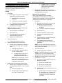
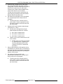
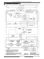
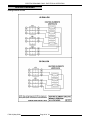
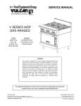
1
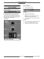
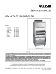
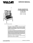
SERVICE MANUAL
ELECTRIC BRAISING PANS
(30 & 40 GALLON)
VE30
ML-126849
VE40
ML-126850
VE40 SHOWN
- NOTICE This Manual is prepared for the use of trained Vulcan Service
Technicians and should not be used by those not properly
qualified. If you have attended a Vulcan Service School for this
product, you may be qualified to perform all the procedures
described in this manual.
This manual is not intended to be all encompassing. If you have
not attended a Vulcan Service School for this product, you should
read, in its entirety, the repair procedure you wish to perform to
determine if you have the necessary tools, instruments and skills
required to perform the procedure. Procedures for which you do
not have the necessary tools, instruments and skills should be
performed by a trained Vulcan Service Technician.
Reproduction or other use of this Manual, without the express
written consent of Vulcan, is prohibited.
For additional information on Vulcan-Hart Company or to locate an authorized parts
and service provider in your area, visit our website at www.vulcanhart.com.
A product of VULCAN-HART
LOUISVILLE, KY 40201-0696
F35410 (May 2003)
ELECTRIC BRAISING PAN
TABLE OF CONTENTS
GENERAL . . . . . . . . . . . . . . . . . . . . . . . . . . . . . . . . . . . . . . . . . . . . . . . . . . . . . . . . . . . . . . . . . . . . . . . . . . . . . . . .
Installation, Operation and Cleaning . . . . . . . . . . . . . . . . . . . . . . . . . . . . . . . . . . . . . . . . . . . . . . . . . . . . . . . . .
Introduction . . . . . . . . . . . . . . . . . . . . . . . . . . . . . . . . . . . . . . . . . . . . . . . . . . . . . . . . . . . . . . . . . . . . . . . . . . . .
Control Panel . . . . . . . . . . . . . . . . . . . . . . . . . . . . . . . . . . . . . . . . . . . . . . . . . . . . . . . . . . . . . . . . . . . . . .
Model Designations . . . . . . . . . . . . . . . . . . . . . . . . . . . . . . . . . . . . . . . . . . . . . . . . . . . . . . . . . . . . . . . . .
Tools . . . . . . . . . . . . . . . . . . . . . . . . . . . . . . . . . . . . . . . . . . . . . . . . . . . . . . . . . . . . . . . . . . . . . . . . . . . . . . . . .
Specifications . . . . . . . . . . . . . . . . . . . . . . . . . . . . . . . . . . . . . . . . . . . . . . . . . . . . . . . . . . . . . . . . . . . . . . . . . .
3
3
3
3
3
3
4
REMOVAL AND REPLACEMENT OF PARTS . . . . . . . . . . . . . . . . . . . . . . . . . . . . . . . . . . . . . . . . . . . . . . . . . . . . 4
Covers and Panels . . . . . . . . . . . . . . . . . . . . . . . . . . . . . . . . . . . . . . . . . . . . . . . . . . . . . . . . . . . . . . . . . . . . . . 4
Power Supply Box Components . . . . . . . . . . . . . . . . . . . . . . . . . . . . . . . . . . . . . . . . . . . . . . . . . . . . . . . . . . . . 5
Temperature Controller . . . . . . . . . . . . . . . . . . . . . . . . . . . . . . . . . . . . . . . . . . . . . . . . . . . . . . . . . . . . . . . . . . 6
Pan Position/Down Limit Switch . . . . . . . . . . . . . . . . . . . . . . . . . . . . . . . . . . . . . . . . . . . . . . . . . . . . . . . . . . . . 7
Up Limit Switch . . . . . . . . . . . . . . . . . . . . . . . . . . . . . . . . . . . . . . . . . . . . . . . . . . . . . . . . . . . . . . . . . . . . . . . . . 9
Lid Switch . . . . . . . . . . . . . . . . . . . . . . . . . . . . . . . . . . . . . . . . . . . . . . . . . . . . . . . . . . . . . . . . . . . . . . . . . . . . . 9
Thermocouple Probe . . . . . . . . . . . . . . . . . . . . . . . . . . . . . . . . . . . . . . . . . . . . . . . . . . . . . . . . . . . . . . . . . . . . 9
DC Lift Motor . . . . . . . . . . . . . . . . . . . . . . . . . . . . . . . . . . . . . . . . . . . . . . . . . . . . . . . . . . . . . . . . . . . . . . . . . 10
Gear Reducer . . . . . . . . . . . . . . . . . . . . . . . . . . . . . . . . . . . . . . . . . . . . . . . . . . . . . . . . . . . . . . . . . . . . . . . . . 11
Heating Elements . . . . . . . . . . . . . . . . . . . . . . . . . . . . . . . . . . . . . . . . . . . . . . . . . . . . . . . . . . . . . . . . . . . . . . 12
High Limit Thermostat . . . . . . . . . . . . . . . . . . . . . . . . . . . . . . . . . . . . . . . . . . . . . . . . . . . . . . . . . . . . . . . . . . 13
Lid Springs . . . . . . . . . . . . . . . . . . . . . . . . . . . . . . . . . . . . . . . . . . . . . . . . . . . . . . . . . . . . . . . . . . . . . . . . . . . 13
SERVICE PROCEDURES AND ADJUSTMENTS . . . . . . . . . . . . . . . . . . . . . . . . . . . . . . . . . . . . . . . . . . . . . . . . .
Temperature Controller Calibration . . . . . . . . . . . . . . . . . . . . . . . . . . . . . . . . . . . . . . . . . . . . . . . . . . . . . . . .
Temperature Controller Test . . . . . . . . . . . . . . . . . . . . . . . . . . . . . . . . . . . . . . . . . . . . . . . . . . . . . . . . . . . . .
Thermocouple Test . . . . . . . . . . . . . . . . . . . . . . . . . . . . . . . . . . . . . . . . . . . . . . . . . . . . . . . . . . . . . . . . . . . .
Heating Element Test . . . . . . . . . . . . . . . . . . . . . . . . . . . . . . . . . . . . . . . . . . . . . . . . . . . . . . . . . . . . . . . . . . .
DC Motor Controller Test . . . . . . . . . . . . . . . . . . . . . . . . . . . . . . . . . . . . . . . . . . . . . . . . . . . . . . . . . . . . . . . .
Pan Position/Down Limit Switch Adjustment . . . . . . . . . . . . . . . . . . . . . . . . . . . . . . . . . . . . . . . . . . . . . . . . .
Lid Switch Adjustment . . . . . . . . . . . . . . . . . . . . . . . . . . . . . . . . . . . . . . . . . . . . . . . . . . . . . . . . . . . . . . . . . .
Lid Spring Tension Adjustment . . . . . . . . . . . . . . . . . . . . . . . . . . . . . . . . . . . . . . . . . . . . . . . . . . . . . . . . . . . .
15
15
16
16
17
17
18
19
20
ELECTRICAL OPERATION . . . . . . . . . . . . . . . . . . . . . . . . . . . . . . . . . . . . . . . . . . . . . . . . . . . . . . . . . . . . . . . . . .
Component Function . . . . . . . . . . . . . . . . . . . . . . . . . . . . . . . . . . . . . . . . . . . . . . . . . . . . . . . . . . . . . . . . . . .
Component Location . . . . . . . . . . . . . . . . . . . . . . . . . . . . . . . . . . . . . . . . . . . . . . . . . . . . . . . . . . . . . . . . . . .
Sequence of Operation . . . . . . . . . . . . . . . . . . . . . . . . . . . . . . . . . . . . . . . . . . . . . . . . . . . . . . . . . . . . . . . . . .
Schematic Diagram . . . . . . . . . . . . . . . . . . . . . . . . . . . . . . . . . . . . . . . . . . . . . . . . . . . . . . . . . . . . . . . . . . . .
Wiring Diagrams . . . . . . . . . . . . . . . . . . . . . . . . . . . . . . . . . . . . . . . . . . . . . . . . . . . . . . . . . . . . . . . . . . . . . . .
Heating Element Circuits . . . . . . . . . . . . . . . . . . . . . . . . . . . . . . . . . . . . . . . . . . . . . . . . . . . . . . . . . . . .
Terminal Block Wiring . . . . . . . . . . . . . . . . . . . . . . . . . . . . . . . . . . . . . . . . . . . . . . . . . . . . . . . . . . . . . .
21
21
22
23
25
26
26
27
TROUBLESHOOTING . . . . . . . . . . . . . . . . . . . . . . . . . . . . . . . . . . . . . . . . . . . . . . . . . . . . . . . . . . . . . . . . . . . . . . 28
Electric Heating (Manual Lift or Motorized Lift Option) . . . . . . . . . . . . . . . . . . . . . . . . . . . . . . . . . . . . . . . . . . 28
Motorized Lift Option Only . . . . . . . . . . . . . . . . . . . . . . . . . . . . . . . . . . . . . . . . . . . . . . . . . . . . . . . . . . . . . . . 29
CONDENSED SPARE PARTS LIST . . . . . . . . . . . . . . . . . . . . . . . . . . . . . . . . . . . . . . . . . . . . . . . . . . . . . . . . . . . 32
© VULCAN 2003
F35410 (May 2003)
Page 2 of 32
ELECTRIC BRAISING PAN
GENERAL
Model Designations
INSTALLATION, OPERATION
AND CLEANING
Refer to the Installation & Operation Manual for
specific instructions.
!
VE30 - 30 gallon capacity
!
VE40 - 40 gallons capacity
TOOLS
INTRODUCTION
Standard
The tilting braising pan (skillet) is a versatile piece
of cooking equipment. It can be used to stew,
simmer, steam, sear, pan fry, grill or saute food
products over an evenly distributed heating surface.
Once the product is fully cooked, the pan can be
tilted for ease of product removal.
!
Standard set of hand tools.
!
VOM with an AC current tester.
NOTE: Any quality VOM with a sensitivity of
20,000 ohms per volt can be used.
!
Control Panel
Temperature tester (thermocouple type) with
surface probe.
Special
!
1 5/8" open end wrench. Used for removing lid
springs and adjusting lid spring tension.
!
Field service grounding kit P/N TL- 84919.
Page 3 of 32
F35410 (May 2003)
ELECTRIC BRAISING PANS - REMOVAL AND REPLACEMENT OF PARTS
SPECIFICATIONS
AMPERAGE PER LINE
VOLTS
VE30
PHASE
VE40
TOTAL
KW
L1-L3
TOTAL
KW
L1
L2
L3
208
1
9
43
12
58
58
---
240
1
12
50
16
67
67
---
208
3
9
25
12
39
39
25
240
3
12
29
16
46
46
29
480
3
12
15
16
23
23
15
NOTES:
1. Amperage values in the table are nominal. Tolerance is +5/-10%.
2. Voltage values are @ 60HZ.
3. All models are shipped for 208/240V three phase connections. If a 208/240V single phase connection is
needed, the machine is field convertible at the terminal block. See wiring diagram AI1378.
4. On all 208V machines, the 240V heating element is being used (total KW output is reduced).
5. On VE40 three phase machines only, the heating elements are wired to be an unbalanced load.
REMOVAL AND REPLACEMENT OF PARTS
Control Panel
COVERS AND PANELS
WARNING: DISCONNECT THE
ELECTRICAL POWER TO THE
MACHINE AND FOLLOW LOCKOUT /
TAGOUT PROCEDURES.
1.
Remove front panel.
2.
Disconnect conduit from control box.
3.
Remove manual lift crank handle (if installed).
4.
Remove bolts securing control panel to braising
pan frame. Bolts are recessed in the frame
channel.
Front, Rear & Side Panels
1.
Lift up on the bottom edge of panel until it clears
the catch.
2.
Tilt outwards and allow the panel to drop down.
3.
Reverse procedure to install.
F35410 (May 2003)
Page 4 of 32
ELECTRIC BRAISING PANS - REMOVAL AND REPLACEMENT OF PARTS
9.
Control panel is removed.
10. To install.
5.
Align tab on potentiometer with positioning
bracket on panel.
B.
Install mounting nut and tighten.
C.
Adjust stop nut on potentiometer body (as
necessary) to ensure a water tight seal on
mounting nut.
D.
Attach temperature dial.
Tilt bottom of control panel outwards and pull
down.
NOTE: The control panel should be supported to
remove lead wire strain.
6.
A.
Remove control box from control panel.
11. Reverse procedure from step 6 to complete the
installation.
12. Check calibration as outlined under
TEMPERATURE CONTROLLER
CALIBRATION.
7.
POWER SUPPLY BOX
COMPONENTS
Disconnect lead wires from control switch.
WARNING: DISCONNECT THE
ELECTRICAL POWER TO THE
MACHINE AND FOLLOW LOCKOUT /
TAGOUT PROCEDURES.
8.
Pull temperature dial from potentiometer shaft
and remove mounting nut.
CAUTION: Certain components in this system
are subject to damage by electrostatic discharge
during field repairs. A field service grounding kit
is available to prevent damage. The field service
grounding kit must be used anytime a control
board is handled.
1.
Page 5 of 32
Remove front panel as outlined under
COVERS AND PANELS.
F35410 (May 2003)
ELECTRIC BRAISING PANS - REMOVAL AND REPLACEMENT OF PARTS
2.
Remove power supply box cover.
3.
Disconnect lead wires then remove the
component being replaced.
4.
Reverse procedure to install the replacement
component.
5.
Check braising pan for proper operation.
4.
Pull temperature dial from potentiometer shaft
and remove mounting nut.
5.
To install:
TEMPERATURE CONTROLLER
WARNING: DISCONNECT THE
ELECTRICAL POWER TO THE
MACHINE AND FOLLOW LOCKOUT /
TAGOUT PROCEDURES.
1.
Remove control box from the control panel as
outlined under COVERS AND PANELS.
2.
Disconnect lead wires from temperature
controller.
3.
Remove temperature controller from control
box.
6.
F35410 (May 2003)
Page 6 of 32
A.
Align tab on potentiometer with positioning
bracket on panel.
B.
Install mounting nut and tighten.
C.
Adjust stop nut on potentiometer body (as
necessary) to ensure a water tight seal on
mounting nut.
D.
Attach temperature dial.
Reverse procedure from step 3 to complete the
installation.
ELECTRIC BRAISING PANS - REMOVAL AND REPLACEMENT OF PARTS
7.
Check calibration as outlined under
TEMPERATURE CONTROLLER
CALIBRATION.
PAN POSITION/DOWN LIMIT
SWITCH
WARNING: DISCONNECT THE
ELECTRICAL POWER TO THE
MACHINE AND FOLLOW LOCKOUT /
TAGOUT PROCEDURES.
1.
Remove front and left side panels as outlined
under COVERS AND PANELS.
2.
Remove strain relief nut from end of strain
relief body and remove pan position/down limit
switch from switch mounting bracket.
LEFT SIDE VIEW SHOWN
NOTE: When installing, ensure the o-ring seal is
inserted into the strain relief body (around power
cable) before tightening strain relief nut.
6.
To install:
A.
Position the switch with the head pointing
toward installer and gear cam pointing up.
NOTE: The plunger on the head is spring loaded
and will push the head away from switch body when
the last screw is removed.
B.
Remove screws securing the head to
switch body, rotate 90° clockwise and
tighten screws to secure.
TOP VIEW SHOWN
3.
Remove cover from switch.
4.
Disconnect lead wires and pull wires thru strain
relief body.
5.
Remove strain relief body from switch.
C.
Page 7 of 32
Place switch on its side with the head to
the left and gear cam pointing up.
F35410 (May 2003)
ELECTRIC BRAISING PANS - REMOVAL AND REPLACEMENT OF PARTS
D.
Align roller arm adaptor with the four
locking tabs pointing up and position one
of the tabs at 0°.
NOTE: The 0° position of the roller arm locking tab
is the starting point for alignment only. The locking
tab cannot remain at the 0° position.
SIDE VIEW SHOWN
E.
Place roller arm adaptor on the gear cam
to engage the teeth. Lift the adaptor until
the teeth just slightly disengage from the
gear cam. Rotate the roller arm adaptor
counterclockwise 1 tooth, re-engage teeth
and release the adaptor.
G.
Verify roller arm position on switch.
1)
F.
Measure the distance from the rear of
the switch body to the center of the
roller. The distance should be 3".
Align the roller arm slots with the four
locking tabs on the roller arm adaptor and
tighten mounting screw to secure.
F35410 (May 2003)
Page 8 of 32
H.
If distance is ok, proceed to step 7.
I.
If distance is not ok, adjust the roller arm
position (as necessary) to obtain the 3"
roller arm dimension.
ELECTRIC BRAISING PANS - REMOVAL AND REPLACEMENT OF PARTS
7.
Reverse procedure from step 5 to complete the
installation.
8.
Adjust pan position/down limit switch on switch
mounting bracket as outlined under PAN
POSITION/DOWN LIMIT SWITCH
ADJUSTMENT in SERVICE PROCEDURES
AND ADJUSTMENTS.
UP LIMIT SWITCH
WARNING: DISCONNECT THE
ELECTRICAL POWER TO THE
MACHINE AND FOLLOW LOCKOUT /
TAGOUT PROCEDURES.
1.
Remove front panel as outlined under
COVERS AND PANELS.
2.
Disconnect lead wires from switch.
3.
Remove switch from mounting bracket.
4.
Reverse procedure to install and check for
proper operation.
2.
Remove switch from lid support bracket.
3.
Lift terminal cover off switch body and
disconnect lead wires.
4.
Reverse procedure to install and adjust switch
as outlined under LID SWITCH ADJUSTMENT
in SERVICE PROCEDURES AND
ADJUSTMENTS.
LID SWITCH
THERMOCOUPLE PROBE
WARNING: DISCONNECT THE
ELECTRICAL POWER TO THE
MACHINE AND FOLLOW LOCKOUT /
TAGOUT PROCEDURES.
1.
Remove lid switch cover from lid switch
support bracket.
WARNING: DISCONNECT THE
ELECTRICAL POWER TO THE
MACHINE AND FOLLOW LOCKOUT /
TAGOUT PROCEDURES.
1.
Access temperature controller as outlined under
TEMPERATURE CONTROLLER .
2.
Disconnect thermocouple lead wires.
3.
Raise the pan to the full tilt position.
4.
Remove harness cover.
Page 9 of 32
F35410 (May 2003)
ELECTRIC BRAISING PANS - REMOVAL AND REPLACEMENT OF PARTS
NOTE: When installing: Route thermocouple wire in
the same manner thru the metal clamps on the hinge
& frame. Tighten thermocouple just until it touches
the pan; do not over tighten or damage to the
thermocouple may occur.
DC LIFT MOTOR
WARNING: DISCONNECT THE
ELECTRICAL POWER TO THE
MACHINE AND FOLLOW LOCKOUT /
TAGOUT PROCEDURES.
5.
Remove the insulation cover.
6.
Loosen lock nut and remove threaded probe
from pan.
7.
Reverse procedure to install and check braising
pan for proper operation.
F35410 (May 2003)
1.
Remove front, rear and right side panels as
outlined under COVERS AND PANELS.
2.
Remove power supply box cover.
3.
Disconnect DC lift motor lead wires labeled
MTR+ (positive) & MTR - (negative).
NOTE: Lead wires can be identified by label or
marking on the wire.
Page 10 of 32
ELECTRIC BRAISING PANS - REMOVAL AND REPLACEMENT OF PARTS
4.
Loosen the strain relief nut and the hold down
clamps for the motors' power cable. Pull the
cable thru the strain relief opening and remove
the cable from underneath the clamps.
VE30 REAR VIEW SHOWN
5.
Remove motor mounting bolts from gear
reducer flange.
6.
Remove motor from gear reducer.
7.
8.
Lower the pan (use motorized pan lift or manual
crank handle).
3.
If DC lift motor is installed, remove motor as
outlined under DC LIFT MOTOR.
4.
Remove lock nut securing crank assembly to lift
arm.
5.
Remove bolts securing gear reducer to braising
pan frame then remove gear reducer.
6.
Loosen set screw on crank assembly and
remove the assembly from drive shaft.
7.
Loosen set screw on shaft extension coupling
and remove the coupling from manual crank
shaft.
To install:
A.
With drive key on shaft, install motor to
gear reducer.
B.
Route and secure the motors' power cable
and re-connect motor lead wires.
C.
Replace power supply box cover and side
panels.
Check for proper operation.
GEAR REDUCER
WARNING: DISCONNECT THE
ELECTRICAL POWER TO THE
MACHINE AND FOLLOW LOCKOUT /
TAGOUT PROCEDURES.
1.
2.
Remove right side and rear panels as outlined
under COVERS AND PANELS.
Page 11 of 32
F35410 (May 2003)
ELECTRIC BRAISING PANS - REMOVAL AND REPLACEMENT OF PARTS
HEATING ELEMENTS
WARNING: DISCONNECT THE
ELECTRICAL POWER TO THE
MACHINE AND FOLLOW LOCKOUT /
TAGOUT PROCEDURES.
8.
1.
Raise the pan to the full tilt position.
2.
Remove harness cover.
3.
Disconnect lead wires from the heating
element being replaced.
4.
Remove the insulation cover.
5.
Remove heating element clamps (spring
loaded) from the clamp holder then remove
heating element.
To install:
A.
With drive key on drive shaft, install crank
assembly and tighten set screw against
key.
B.
With drive key on manual crank shaft,
install shaft extension coupling and tighten
set screw against key.
C.
Place gear reducer in its mounting location
on frame. Position gear reducer so the
shaft extension coupling is aligned with the
opening in control panel; and the lift arm is
vertical and parallel to the crank assembly
when connected.
NOTE: On the bottom lift arm bushing, the bushing
head must be positioned between the lift arm and
the crank assembly to create approximately 1/32"
spacing.
9.
Reverse procedure from step 5 to complete the
installation.
10. Check for proper operation.
F35410 (May 2003)
Page 12 of 32
ELECTRIC BRAISING PANS - REMOVAL AND REPLACEMENT OF PARTS
5.
6.
Reverse procedure to install and check for
proper operation.
LID SPRINGS
HIGH LIMIT THERMOSTAT
WARNING: DISCONNECT THE
ELECTRICAL POWER TO THE
MACHINE AND FOLLOW LOCKOUT /
TAGOUT PROCEDURES.
WARNING: DISCONNECT THE
ELECTRICAL POWER TO THE
MACHINE AND FOLLOW LOCKOUT /
TAGOUT PROCEDURES.
1.
1.
Raise the pan to the full tilt position.
2.
Remove the harness cover.
Reverse procedure to install and check
braising pan for proper operation.
Lower the lid to the full down position.
NOTE: For spring tension to be set correctly, both
the left and right side springs must be replaced.
2.
Remove spring covers by prying up at the
bottom. The covers are held in place by tabs on
the bottom of cover.
RIGHT SIDE REAR VIEW SHOWN
3.
Disconnect lead wires from the high limit
thermostat.
4.
Remove thermostat from insulation cover.
3.
Page 13 of 32
Place a 1 5/8" wrench on the lid spring lock nut
and apply a downward force until locking pin
can be removed. Continue to hold lock nut in
place.
F35410 (May 2003)
ELECTRIC BRAISING PANS - REMOVAL AND REPLACEMENT OF PARTS
D.
Caution: Do not release wrench while locking pin
is removed or damage to the braising pan may
occur.
A.
Slowly release downwards force to remove
spring tension.
B.
Rotate lid spring lock nut to the next hole
position then replace locking pin. Continue
until all spring tension is removed, one
position at a time.
C.
4.
Remove bolts securing the inside lid
bearing housing to the lid support bracket.
F35410 (May 2003)
Remove lid bearing housing, lid spring lock
nut and the spring, from spring mandrel.
To install:
A.
Slide the spring onto the lid spring
mandrel. Insert spring into locator hole on
the lid spring retainer.
B.
Slide the lid spring lock nut onto the lid
spring mandrel. Insert spring into locator
hole on the lid spring lock nut.
C.
Replace lid bearing housing.
5.
Replace spring on the opposite side.
6.
Adjust spring tension as outlined under LID
SPRING TENSION ADJUSTMENT IN
SERVICE PROCEDURES AND
ADJUSTMENTS.
Page 14 of 32
ELECTRIC BRAISING PANS - SERVICE PROCEDURES AND ADJUSTMENTS
SERVICE PROCEDURES AND ADJUSTMENTS
WARNING: CERTAIN PROCEDURES IN THIS SECTION REQUIRE ELECTRICAL TEST OR MEASUREMENTS
WHILE POWER IS APPLIED TO THE MACHINE. EXERCISE EXTREME CAUTION AT ALL TIMES. IF TEST
POINTS ARE NOT EASILY ACCESSIBLE, DISCONNECT POWER AND FOLLOW LOCKOUT / TAGOUT
PROCEDURES, ATTACH TEST EQUIPMENT AND REAPPLY POWER TO TEST.
TEMPERATURE CONTROLLER
CALIBRATION
NOTE: Verify condition of thermocouple as outlined
under THERMOCOUPLE TEST before proceeding.
1.
At the geometric center on the pan cooking
surface, clean an area approximately 3" inches
in diameter.
2.
Apply a thin layer of fresh cooking oil to the
cleaned area and place a temperature sensing
disk on the pan cooking surface.
3.
Turn on/off switch on and set temperature dial
to 250°F.
4.
5.
Monitor the heat light (red) on the control panel.
When temperature controller is calling for heat,
light will be on. If temperature controller is
satisfied, light will be off.
A.
Allow the temperature controller to cycle
three times to stabilize the pan
temperature.
B.
Record the temperature when the
temperature controller cycles off and on for
the next three cycles.
B.
If the average temperature is more than
10°F of the dial setting, temperature
controller calibration must be adjusted.
Using the temperature scale on the overlay as a
guide, align the edge on a short piece of tape to
the temperature calculated in step 6 and apply
tape to knob as a reference point.
8.
Remove temperature dial from shaft.
9.
Loosen screws on the back of dial.
A.
Hold the knob and rotate dial to the edge of
the tape used for reference. This
adjustment offsets the indicated
temperature on the dial to the actual
temperature measured.
NOTE: With knob facing user, a clockwise
rotation increases temperature and a counterclockwise rotation decrease temperature.
B.
Hold the dial & knob together to maintain
the adjusted setting and tighten screws.
The differential calculated should be less
than 20°F.
1)
If the differential is less than 20°F,
temperature controller is functioning
properly.
a.
2)
Proceed to average temperature.
If the differential is more than 20°F,
the temperature controller is
malfunctioning.
a.
6.
If the average temperature is less than
10°F of the dial setting, temperature
controller is properly calibrated.
7.
Calculate the differential by subtracting the
temperature indicated when heat light goes out
from temperature indicated when heat light
comes on.
A.
A.
Install a replacement
temperature controller and check
calibration.
Calculate the average temperature by adding
the temperature indicated when the heat lamp
goes out to the temperature indicated when the
heat lamp comes on & divide this answer by 2.
10. Replace temperature dial on shaft.
11. Turn the temperature dial to the lowest setting
then back to 250°F.
Page 15 of 32
F35410 (May 2003)
ELECTRIC BRAISING PANS - SERVICE PROCEDURES AND ADJUSTMENTS
12. Repeat the average temperature calculation for
up to three attempts. Allow the pan to cycle at
least two times between adjustments before
performing the calculation.
7.
Disconnect lead wire labeled HT.0 from the
COM terminal on the controller.
8.
Verify 24VAC between the disconnected HT.0
lead wire and ground.
13. If calibration is unsuccessful, the controller may
be malfunctioning and cannot be adjusted
properly. Install a replacement temperature
controller and check calibration.
TEMPERATURE CONTROLLER
TEST
NOTE: The controller is powered whenever supply
power is connected to the machine.
9.
A.
If correct, re-connect lead wire to COM
terminal and proceed to step 9.
B.
If incorrect, check transformer and the
on/off switch for proper operation.
Disconnect lead wire labeled HT.1 from the
N.O. terminal on the controller.
10. Verify 24VAC between N.O. terminal on the
temperature controller and ground.
A.
If correct, internal relay contacts are
functioning properly. Reconnect lead wire
to the N.O. terminal. See Troubleshooting.
B.
If incorrect, install a replacement
temperature controller and check for
proper operation.
THERMOCOUPLE TEST
1.
Lower the pan to the full down position.
2.
Access the temperature controller as outlined in
REMOVAL AND REPLACEMENT OF PARTS.
3.
Re-connect power to the machine.
4.
Verify temperature controller is receiving
120VAC at terminals L1 & L2, polarity is correct
and machine is properly grounded.
5.
Turn on/off switch on and set temperature dial
to 250/F.
6.
Verify heat light (red) comes on and all heating
elements are energized.
A.
If heat light and heating elements energize
but turn off within 10 seconds, verify
condition of thermocouple as outlined
under THERMOCOUPLE TEST.
1.
Access the temperature controller as outlined
in REMOVAL AND REPLACEMENT OF
PARTS.
2.
Remove thermocouple lead wires from
temperature controller.
3.
Check the thermocouple for resistance.
A.
NOTE: Temperature controller will de-energize
internal relay if the circuitry detects an open
thermocouple.
B.
If heat light and heating elements do not
energize, verify internal relay contacts are
operating properly.
F35410 (May 2003)
4.
Page 16 of 32
If meter reads an overload (OL) condition
(open), or zero ohms (short) replace the
thermocouple and check temperature
controller for proper operation.
If resistance is measured, thermocouple is
good.
ELECTRIC BRAISING PANS - SERVICE PROCEDURES AND ADJUSTMENTS
HEATING ELEMENT TEST
DC MOTOR CONTROLLER TEST
VOLTAGE
KW PER
ELEMENT
AMPS PER
ELEMENT
OHMS PER
ELEMENT
208
4
14.3
13.7
240
4
16.7
13.7
480
4
8.7
55.5
NOTES:
1. Values in the table are nominal.
Tolerance is +5/-10%.
2. Voltage values are @ 60HZ.
3. Resistance values (ohms) are @ room
temperature.
4. On all 208V machines, the 240V heating
element is being used (KW output is
reduced).
1.
Access the heating elements as outlined in
REMOVAL AND REPLACEMENT OF PARTS.
2.
Measure voltage at heating element terminals
and verify it against data plate voltage.
A.
If voltage is incorrect, see
TROUBLESHOOTING.
B.
If voltage is correct, check current draw
(amps) through the heating element lead
wires.
NOTE: This method is preferred over a
resistance check when a clamp on type amp
meter is available.
1)
2)
If current draw is correct then heating
element is functioning properly. See
table for proper values.
If current draw is not correct, turn
on/off switch to OFF and disconnect
the electrical supply.
a.
C.
3.
1.
Lower the pan to the full down position.
2.
Raise the lid to the full open position.
3.
Access the DC motor controller as outlined
under POWER SUPPLY BOX COMPONENTS
in REMOVAL AND REPLACEMENT OF
PARTS.
4.
Set VOM to measure AC volts and connect
meter leads at L1 & L2 on the controller.
5.
Turn the on/off switch to on.
6.
Verify 120VAC at L1 & L2 on the controller
when the lift control switch (momentary) is
operated to raise & lower the pan.
Replace heating element then
proceed to step 3.
If unable to check current draw, a
resistance check may indicate a
malfunctioning element.
1)
Turn the on/off switch off and
disconnect power to the machine.
2)
Remove the lead wires from the
heating element and check
resistance (ohms). See table for
proper values.
Check for proper operation.
A.
If voltage is present but pan does not raise
& lower, proceed to step 7.
B.
If voltage is not present refer to
MOTORIZED LIFT OPTION ONLY under
TROUBLESHOOTING.
7.
Disconnect power to the machine.
8.
Set VOM to measure DC volts and connect
VOM leads to terminals A + (positive) & A (negative) on the controller.
9.
Re-connect power to the machine.
10. Verify 90VDC (approximate) from the DC
motor controller when the lift control switch
(momentary) is operated to raise & lower the
pan.
Page 17 of 32
F35410 (May 2003)
ELECTRIC BRAISING PANS - SERVICE PROCEDURES AND ADJUSTMENTS
A.
If voltage is present but pan does not
raise, refer to MOTORIZED LIFT OPTION
ONLY under TROUBLESHOOTING.
1)
If heating elements do not energize:
Verify 24VAC input to the switch and
24VAC is output from the switch.
B.
If voltage is not present and the fuse is ok,
turn the on/off switch off and disconnect
power to the machine.
2)
If voltage is present on the output
side of the switch, the switch is
functioning properly. See
TROUBLESHOOTING.
3)
If voltage is not present on the output
side of the switch, install a
replacement pan position/down limit
switch and repeat this procedure to
adjust.
11. Install a replacement DC motor controller and
check for proper operation.
PAN POSITION/DOWN LIMIT
SWITCH ADJUSTMENT
NOTE: Do not use the motorized lift (if installed) for
this procedure.
1.
Turn the on/off switch off.
2.
Remove front and left side panels as outlined
under COVERS AND PANELS.
3.
Insert the manual crank handle.
4.
5.
8.
Verify pan position/down limit switch N.O.
contacts are opening.
A.
Slowly raise the pan until the heat light
and heating elements de-energize then
stop.
B.
Raise the pan to the full tilt position.
At the rear of the pan, measure the
distance from the bottom of the pan skirt
to the flat surface covering the frame.
Verify roller arm position on switch.
1)
A.
Measure the distance from the rear of the
switch body to the center of the roller. The
distance should be 3".
Distance should be 2.25" to 2.50".
LEFT SIDE VIEW SHOWN
SIDE VIEW SHOWN
B.
If distance is ok, proceed to step 6.
C.
If distance is not ok, position the roller arm
as outlined under PAN POSITION/DOWN
LIMIT SWITCH in REMOVAL AND
REPLACEMENT OF PARTS.
6.
Lower the pan to the full down position. The
roller should make contact with the hinge and
operate the switch.
7.
Verify pan position/down limit switch N.O.
contacts are closing.
9.
If heat light and heating elements de-energize;
and the measured distance is within the
acceptable range, switch is adjusted properly.
If both conditions are not satisfied, adjustment
is necessary.
10. To Adjust:
A.
A.
Turn the on/off switch on and set the
temperature dial to call for heat.
B.
Heat light (red) comes on and all heating
elements are energized.
F35410 (May 2003)
NOTE: For reference, this is approximately 5
angular degrees.
Page 18 of 32
Loosen screws on the mounting switch
bracket.
ELECTRIC BRAISING PANS - SERVICE PROCEDURES AND ADJUSTMENTS
LEFT SIDE VIEW SHOWN
B.
Adjust mounting switch bracket up or
down (as necessary) to obtain the rear
pan dimension of 2.25" to 2.50".
5.
The lid switch actuator should make contact
with the trigger (cam) and operate the lid
switch.
6.
Operate the "lift control switch" to raise the
pan.
11. Repeat steps 5 thru 9 to check for proper
operation.
LID SWITCH ADJUSTMENT
CAUTION: Lid switch should not allow pan to be
raised if the lid is not opened a minimum of 23"
or damage to the lid may occur.
1.
Turn the on/off switch on.
2.
Raise the lid to the full open position.
3.
Lower the pan to the full down position.
4.
Lower the lid to an open height dimension of
23" to 23 1/2" (minimum is 23").
A.
If pan raises, the lid switch is functioning
properly.
B.
If pan does not raise, continue with
procedure.
7.
Remove lid switch cover from lid support
bracket.
8.
To adjust:
NOTE: For reference, this is approximately 45
angular degrees.
A.
Page 19 of 32
With the lid raised to an open height
dimension of 23" to 23 1/2" (minimum is
23"), loosen lid switch mounting screws
and adjust switch position to operate the
switch. Re-tighten screws.
F35410 (May 2003)
ELECTRIC BRAISING PANS - SERVICE PROCEDURES AND ADJUSTMENTS
3.
To adjust:
A.
Place a 1 5/8" wrench on the lid spring
lock nut and apply a downward force until
locking pin can be removed. Continue to
hold lock nut in place.
CAUTION: Do not release wrench while locking
pin is removed or damage to the braising pan
may occur.
B.
If additional adjustment is necessary,
push up on the tip of the switch actuator to
slightly bend the actuator around the
mating edge of the trigger (cam).
C.
Verify pan will raise by operating lift
control switch.
D.
Repeat the adjustment (as necessary) and
check for proper operation.
LID SPRING TENSION
ADJUSTMENT
1.
Apply additional downward force to
increase spring tension; or slowly release
downwards force to decrease spring
tension.
C.
Rotate lid spring lock nut to the next hole
position then replace locking pin. Adjust
the spring tension, one position at a time.
D.
Repeat tension adjustment on the
opposite spring.
Raise the lid and release at several positions
thru the range of travel.
A.
If lid remains in place, no adjustment is
necessary.
B.
If lid does not remain in place (springs up
or falls down), continue with procedure.
NOTE: For spring tension to be set correctly, each
spring must be adjusted the same amount.
2.
B.
4.
Remove spring covers by prying up at the
bottom. The covers are held in place by tabs
on the bottom of cover.
RIGHT SIDE REAR VIEW SHOWN
F35410 (May 2003)
Page 20 of 32
Repeat step 1 to verify adjustment. Make
additional adjustments as necessary.
ELECTRIC BRAISING PANS - ELECTRICAL OPERATION
ELECTRICAL OPERATION
COMPONENT FUNCTION
BRAISING PAN CONTROLS
Temperature Controller . . . Monitors thermocouple input (type E) and regulates braising pan temperature.
An external set point potentiometer is used for temperature adjustments.
120/24VAC Transformer . . . Supplies 24VAC for heating control circuit. If motorized pan lift option is
installed, supplies 24VAC for lift control circuit.
240-480/120VAC
Transformer . . . . . . . . . . . . . Supplies 120VAC for control circuit.
ON/OFF Switch . . . . . . . . . . Controls 24VAC to the heating control circuit. If motorized pan lift option is
installed, controls power to the lift control circuit.
Power On Light (Amber) . . . Indicates on/off switch is turned on.
Heat Light (Red)
. . . . . . . . . Indicates temperature controller is calling for heat and pan is down.
Pan Position/
Down Limit Switch . . . . . . . N.O. contacts function as pan position switch to power the heating circuit when
pan is down. Removes power from heating circuit when pan is raised. The N.C.
contacts are used for the down limit switch (motorized lift option only).
Fuses F1 & F2 . . . . . . . . . . . Protects control circuit if current exceeds the rated amperage.
K3 Heat Relay . . . . . . . . . . . Supplies power to contactor coils C1, C2 & C3.
Contactors C1, C2, C3 . . . . Supplies line voltage to heating elements.
Heating Elements . . . . . . . . Produces heat for the braising pan cooking surface.
High Limit Thermostat . . . . Prevents braising pan from reaching excessive temperatures by removing
power to contactors. Monitors surface temperature of the insulation cover and
not the pan. Open at 400/F; close at 360/F (auto reset).
MOTORIZED PAN LIFT OPTION CONTROLS
DC Motor Controller . . . . . . Controls DC lift motor operation for raising & lowering of the pan, and provides
motor acceleration control each time the controller is powered. The controller
outputs approximately 90VDC to power the motor.
DC Lift Motor . . . . . . . . . . . . Operates gear reducer to raise or lower the pan. When the correct voltage
polarity is applied thru K1 contacts, motor rotates CW to raise pan. When
reverse voltage polarity is applied thru K2 contacts, motor rotates CCW to lower
the pan.
Lid Switch
. . . . . . . . . . . . . . Controls 24VAC power to lift control switch. Used to ensure lid is open before
pan can be raised.
Lift Control Switch
(Momentary On/Off/On)
. . . Energizes K1 relay coil thru up limit switch contacts (N.C.) to raise the pan.
Energizes K2 relay coil thru down limit switch contacts (N.C.) to lower the pan.
The switch positions are: Center neutral (starting) position off; Momentary on lower pan; Momentary on - raise pan.
Up Limit Switch . . . . . . . . . . Removes power from K1 relay coil when pan reaches full tilt (pan travel stops).
Pan Position/
Down Limit Switch . . . . . . . N.C. contacts function as down limit switch to remove power from K2 relay coil
when pan is lowered to the down position (pan travel stops). The N.O. contacts
are used for the pan position switch.
Page 21 of 32
F35410 (May 2003)
ELECTRIC BRAISING PANS - ELECTRICAL OPERATION
K1 Up Relay (3PDT)
. . . . . . Supplies power to motorized lift circuit to raise the pan when 24VAC coil is
energized.
K2 Down Relay (3PDT) . . . . Supplies power to motorized lift circuit to lower the pan when 24VAC coil is
energized by the lift control switch.
COMPONENT LOCATION
F35410 (May 2003)
Page 22 of 32
ELECTRIC BRAISING PANS - ELECTRICAL OPERATION
a.
SEQUENCE OF OPERATION
Refer to schematic diagram AI1376 for the electrical
sequence of operation. Manual pan lift is the
standard configuration.
5.
Heating
1.
Conditions.
A.
B.
Braising pan connected to correct supply
voltage and is properly grounded.
Braising pan will continue to cycle with the
temperature controller until the pan is raised or
the on/off switch is turned off.
Motorized Pan Lift (Option)
1)
240-480/120VAC transformer
energized.
Refer to the dashed line sections labeled
MOTORIZED LIFT OPTION on the schematic
diagram for the integration of the motorized pan lift
components into the sequence of operation.
2)
Temperature controller energized.
1.
3)
120/24VAC transformer energized.
Conditions.
A.
Temperature dial at lowest setting
(potentiometer fully CCW).
NOTE: Temperature controller internal relay
contacts remain open (N.O.).
2.
1)
240-480/120VAC transformer
energized.
2)
120/24VAC transformer energized.
Pan temperature is below 200/F.
B.
On/off switch off.
D.
On/off switch off.
C.
Lift control switch off (center position).
E.
Pan position/down limit switch N.O.
contacts closed (pan down).
D.
Lid switch N.O. contacts closed (lid
opened).
F.
High limit thermostat closed.
E.
Up limit switch N.C. contacts closed (pan
position is less than full tilt).
F.
Pan position/down limit switch N.O.
contacts closed; and N.C. contacts open
(pan down).
Turn on/off switch on.
Indicator light (amber) comes on.
Set the temperature dial to call for heat.
A.
Internal relay on temperature controller is
energized and HT.0/HT.1 N.O. contacts
close.
1)
Heat light (red) comes on.
2)
K3 heat relay coil energized and K3
4/7 N.O. contacts close.
a.
NOTE: The pan position/down limit switch are
contained in the same switch body. Both sets of
DPST contacts are utilized.
2.
Contactor coils C1, C2 and C3
(VE40 only) energized and
heating elements are powered.
NOTE: If pan is raised 2.25" to 2.50"
at the rear, pan position/down limit
switch N.O. contacts will open and deenergize K3 heat relay coil.
4.
Braising pan connected to correct supply
voltage and is properly grounded.
C.
A.
3.
Contactor coils C1, C2 and C3
(VE40 only) are de-energized
and power is removed from
heating elements.
Turn on/off switch on.
A.
Indicator light (amber) comes on.
NOTE: If temperature dial is set to call for heat,
contactors C1, C2 and C3 (VE40 only) are
energized thru heat relay K3 4/7 N.O. contacts.
3.
Operate the lift control switch to raise the pan
(momentary on - raise).
A.
K1 relay coil is energized thru the up limit
switch N.C contacts.
Braising pan reaches set point temperature.
1)
K1 4/7 N.O. contacts close.
A.
2)
K1 9/6 N.O. contacts close.
3)
K1 8/5 N.O. contacts close.
Internal relay on temperature controller is
de-energized and HT.0/HT.1 N.O. contacts
open.
1)
Heat light (red) goes out.
2)
K3 heat relay coil de-energized and
K3 4/7 N.O. contacts open.
Page 23 of 32
B.
120VAC to DC motor controller thru K1 4/7
N.O. contacts.
1)
90VDC output is activated at terminals
A + (positive) and A - (negative). DC
lift motor powered thru K1 9/6 N.O.
contacts, K1 8/5 N.O. contacts and
pan raises.
F35410 (May 2003)
ELECTRIC BRAISING PANS - ELECTRICAL OPERATION
4.
When the pan is raised 2.25" to 2.50" at the
rear, pan position/down limit switch contacts
change state. The N.O contacts open to remove
power from K3 heat relay coil; and the N.C
contacts close. Power is then available for K2
relay coil thru the N.C. set of contacts.
The pan can still be raised or lowered thru its
travel range by operating the lift control switch.
Release switch to stop pan travel.
5.
Pan reaches full tilt position, the up limit switch
N.C. contacts open and K1 relay coil is deenergized.
A.
6.
The three sets of K1 contacts return to
N.O. position. Power is removed from the
DC motor controller, the DC lift motor and
pan travel stops.
Operate the lift control switch to lower the pan
(momentary on - lower).
A.
B.
K2 relay coil is energized thru the pan
position/down limit switch N.C contacts.
1)
K2 4/7 N.O. contacts close.
2)
K2 9/6 N.O. contacts close.
3)
K2 8/5 N.O. contacts close.
120VAC to DC motor controller thru K2 4/7
N.O. contacts.
1)
90VDC output is activated at terminals
A + (positive) and A - (negative). DC
lift motor powered thru K2 9/6 N.O.
contacts, K2 8/5 N.O. contacts and
pan lowers.
7.
After the pan leaves the full tilt position, the up
limit switch N.C. contacts close. The direction of
pan travel can then be reversed by un-operating
the switch (pan travel stops) then operating the
switch to raise the pan.
8.
Pan reaches full down position, pan
position/down limit switch N.C. contacts open
and K2 relay coil is de-energized.
A.
The three sets of K2 contacts return to
N.O. position. Power is removed from the
DC motor controller, the DC lift motor and
pan travel stops.
F35410 (May 2003)
Page 24 of 32
ELECTRIC BRAISING PANS - ELECTRICAL OPERATION
SCHEMATIC DIAGRAM
Page 25 of 32
F35410 (May 2003)
ELECTRIC BRAISING PANS - ELECTRICAL OPERATION
WIRING DIAGRAMS
Heating Element Circuits
F35410 (May 2003)
Page 26 of 32
ELECTRIC BRAISING PANS - ELECTRICAL OPERATION
Terminal Block Wiring
Page 27 of 32
F35410 (May 2003)
ELECTRIC BRAISING PANS - TROUBLESHOOTING
TROUBLESHOOTING
ELECTRIC HEATING (MANUAL LIFT OR MOTORIZED LIFT OPTION)
SYMPTOMS
POSSIBLE CAUSES
Braising pan does not heat, power on light is
lit and heat light is lit.
1.
2.
3.
4.
K3 heat relay malfunction.
High limit thermostat open.
Contactor(s) malfunction.
Heating element(s) malfunction.
Braising pan does not heat, power on light is
lit but heat light is not lit.
1.
Pan not fully lowered; pan position/down limit switch out
of adjustment; or pan position/down limit switch
malfunction.
Temperature dial not set to call for heat; temperature
probe malfunction; or temperature controller malfunction.
Interconnecting wiring malfunction.
2.
3.
Braising pan does not heat, power on light is
not lit.
1.
2.
3.
4.
5.
6.
Main circuit breaker off; or control circuit fuse F1 or F2
open.
Supply voltage incorrect.
240-480/120VAC transformer - Missing or incorrect
jumper location; or transformer inoperative.
On/off switch off or malfunction.
120/24VAC transformer inoperative.
Interconnecting wiring malfunction.
Excessive or low heat on cooking surface (no
uneven cooking).
1.
2.
3.
4.
Supply voltage incorrect.
Temperature probe not properly mounted.
Temperature controller calibration.
Temperature probe malfunction; or temperature
controller malfunction.
Hot or cold zones on cooking surface (uneven
cooking).
1.
2.
3.
4.
Supply voltage incorrect.
Heating element(s) not properly mounted.
Contactor(s) malfunction.
Heating element(s) malfunction.
F35410 (May 2003)
Page 28 of 32
ELECTRIC BRAISING PANS - TROUBLESHOOTING
MOTORIZED LIFT OPTION ONLY
SYMPTOM
POSSIBLE CAUSES
Pan will not raise.
1.
2.
3.
4.
5.
6.
7.
8.
9.
10.
Pan will not lower.
1.
2.
Lid switch open (lid not opened) or malfunction.
120/24VAC transformer inoperative.
On/off switch off or malfunction.
Lift control switch malfunction (momentary on - raise).
Up limit switch malfunction.
K1 relay malfunction.
DC motor controller - Fuses open or controller malfunction.
DC Lift motor inoperative.
Gear reducer malfunction.
Interconnecting wiring malfunction.
Lid switch open (lid not opened) or malfunction.
Pan position is below 2.25" to 2.50" at the rear. Raise pan to
return pan position/down limit switch N.C. contacts to closed
position.
3. 120/24VAC transformer inoperative.
4. On/off switch off or malfunction.
5. Lift control switch malfunction (momentary on - lower).
6. Down limit switch malfunction.
7. K2 relay malfunction.
8. DC motor controller - Fuses open or controller malfunction.
9. DC Lift motor inoperative.
10. Gear reducer malfunction.
11. Interconnecting wiring malfunction.
Page 29 of 32
F35410 (May 2003)
ELECTRIC BRAISING PANS - TROUBLESHOOTING
-NOTES-
F35410 (May 2003)
Page 30 of 32
ELECTRIC BRAISING PANS - TROUBLESHOOTING
-NOTES-
Page 31 of 32
F35410 (May 2003)
ELECTRIC BRAISING PANS - CONDENSED SPARE PARTS LIST
CONDENSED SPARE PARTS LIST
VE30 & VE40 BRAISING PANS
DESCRIPTION
PART NUMBER
840115
854511-1
854511-2
854512-1
854517-1
854534-1
854537-1
854545-1
821762
855035-1
411500-12
Contactor 25 Amp
Element 208/240v
Element 480v
Thermocouple-Temperature Probe (E-type)
Switch-Pan Limit (Pan Position/Down Limit)
Temperature Control Board
Switch-Control (Manual Lift)
Relay-heat (24VAC)
High Limit Thermostat
Transformer 240-480/120 50VA (Manual Lift)
Transformer 120/24
PART NUMBER
854495-1
854671-1
854545-1
411496-F1
854717-1
855036-1
854653-1
BRAISING PANS WITH MOTORIZED LIFT OPTION
DESCRIPTION
Switch-Control
Controller-Speed
Relay-up & down (24VAC)
Switch-Micro (Lid)
Switch-Micro (Up Limit)
Transformer 240-480/120 150VA
Motor-Gear
F35410 (May 2003)
NOTES
NOTE
Printed in U.S.A.