1
S/M No. : OR6L773S001
Service Manual
Microwave Oven
Model: KOR-6L773S
✔ Caution
: In this Manual, some parts can be changed for improving,
their performance without notice in the parts list. So, if you
need the latest parts information, please refer to PPL(Parts
Price List) in Service Information Center (http://svc.dwe.co.kr).
Nov. 2011
PRECAUTIONS TO BE OBSERVED BEFORE AND
DURING SERVICING TO AVOID POSSIBLE
EXPOSURE TO EXCESSIVE MICROWAVE ENERGY
(a) Do not operate or allow the oven to be operated with the door open.
(b) Make the following safety checks on all ovens to be serviced before activating the magnetron or other microwave source, and make repairs as necessary: (1) Interlock operation, (2) Proper door closing, (3) Seal and
sealing surfaces (arcing, wear, and other damage), (4) Damage to or loosening of hinges and latches, (5)
Evidence of dropping or abuse.
(c) Before turning on microwave power for any service test or inspection within the microwave gen-erating
compartments, check the magnetron, wave guide or transmission line, and cavity for proper align-ment,
integrity, and connections.
(d) Any defective or misadjusted components in the interlock, monitor, door seal, and microwave generation
and transmission systems shall be repaired, replaced, or adjusted by procedures described in this manual
before the oven is released to the owner.
(e) A microwave leakage check to verify compliance with the Federal performance standard should be performed on each oven prior to release to the owner.
TABLE OF CONTENTS
PRECAUTIONS TO BE OBSERVED BEFORE AND DURING SERVICING TO AVOID POSSIBLE
EXPOSURE TO EXCESSIVE MICROWAVE ENERGY ......................................................................................................1
SAFETY AND PRECAUTIONS ...........................................................................................................................................2
1. FOR SAFE OPERATION ..................................................................................................................................2
2. FOR SAFE SERVICE PROCEDURES .............................................................................................................2
SPECIFICATIONS ...............................................................................................................................................................3
EXTERNAL VIEW................................................................................................................................................................4
1. OUTER DIMENSION.........................................................................................................................................4
2. FEATURES DIAGRAM......................................................................................................................................5
INSTALLATION ...................................................................................................................................................................6
OPERATIONS AND FUNCTIONS.......................................................................................................................................7
DISASSEMBLY AND ASSEMBLY......................................................................................................................................8
INTERLOCK MECHANISM AND ADJUSTMENT.............................................................................................................15
TROUBLESHOOTING GUIDE ..........................................................................................................................................16
MEASUREMENT AND TEST ............................................................................................................................................18
1. MEASUREMENT OF THE MICROWAVE POWER OUTPUT ........................................................................18
2. MICROWAVE RADIATION TEST ...................................................................................................................19
3. COMPONENT TEST PROCEDURE ...............................................................................................................20
WIRING DIAGRAM............................................................................................................................................................21
EXPLODED VIEW AND PARTS LIST...............................................................................................................................22
1. DOOR ASSEMBLY .........................................................................................................................................22
2. CONTROL PANEL ASSEMBLY......................................................................................................................22
3. TOTAL ASSEMBLY.........................................................................................................................................22
1
SAFETY AND PRECAUTIONS
CAUTION
This device is to be Serviced only by Properly Qualified Service Personel. Consult the Service Manual for Proper
Service Procedures to Assure Continued Safety Operation and for Precautions to be Taken to Avoid Possible
Exposure to Excessive Microwave Energy.
1. FOR SAFE OPERATION
Damage that allows the microwave energy (that cooks or heats the food) to escape will result in poor cooking and may
cause serious bodily injury to the operator.
IF ANY OF THE FOLLOWING CONDITIONS EXIST, OPERATOR MUST NOT USE THE APPLIANCE.
(Only a trained service personnel should make repairs.)
(1) A broken door hinge.
(2) A broken door viewing screen.
(3) A broken front panel, oven cavity.
(4) A loosened door lock.
(5) A broken door lock.
The door gasket plate and oven cavity surface should be kept clean.
No grease, soil or spatter should be allowed to build up on these surfaces or inside the oven.
DO NOT ATTEMPT TO OPERATE THIS APPLIANCE WITH THE DOOR OPEN.
The microwave oven has concealed switches to make sure the power is turned off when the door is opened.
Do not attempt to defeat them.
DO NOT ATTEMPT TO SERVICE THIS APPLIANCE UNTIL YOU HAVE READ THIS SERVICE MANUAL.
2. FOR SAFE SERVICE PROCEDURES
1. If the oven is operative prior to servicing, a microwave emission check should be performed prior to servicing the
oven.
2. If any certified oven unit is found to servicing, a microwave emission check should be performed prior to servicing the
oven.
(a) inform the manufacturer, importer or assembler,
(b) repair the unit at no cost to the owner,
(c) attempt to ascertain the cause of the excessive leakage,
(d) tell the owner of the unit not to use the unit until the oven has been brought into compliance.
3. If the oven operates with the door open, the service person should tell the user not to operate the oven and contact
the manufacturer and CDRH immediately.
CAUTION
MICROWAVE RADIATION
PERSONNEL SHOULD NOT BE EXPOSED TO THE MICROWAVE ENERGY WHICH MAY RADIATE FROM
THE MAGNETRON OR OTHER MICROWAVE GENERATING DEVICE IF IT IS IMPROPERLY USED OR
CONNECTED. ALL INPUT AND OUTPUT MICROWAVE CONNECTIONS. WAVEGUIDE FLANGES AND
PASKETS MUST BE SECURE. NEVER OPERATE THE DEVICE WITHOUT A MICROWAVE ENERGY
ABSORBING LOAD ATTACHED. NEVER LOOK INTO AN OPEN SAVEGUIDE OR ANTENNA WHILE THE
DEVICE IS ENERGIZED.
2
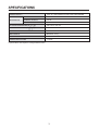
SPECIFICATIONS
POWER SUPPLY
MICROWAVE
230V AC, 50Hz SINGLE PHASE WITH GROUNDING
INPUT POWER
1000 W
ENERGY OUTPUT
700 W
FREQUENCY
2,450MHz
OUTSIDE DIMENSIONS (W
CAVITY DIMENSIONS (W
H
H
D)
D)
446 x 270 x 319 mm
295 x 219 x 303 mm
CAVITY VOLUME
20 L
NET WEIGHT
APPROX. 10 Kg
TIMER
35min. DUAL SPEED
POWER SELECTIONS
7 Levels
* Specifications are subject to change without notice.
3
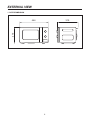
EXTERNAL VIEW
1. OUTER DIMENSION
319
270
446
4
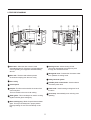
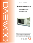
2. FEATURES DIAGRAM
1
2
7
3
6
4
8
5
9
0 q
e
1 Door latch - When the door is closed, it will
automatically shut off. If the door is opened while the
oven is operating, the magnetron will automatically
shut off.
w
8 Viewing screen - Allows viewing of food.
The screen is designed so that light can pass
through, but not the microwave.
9 Waveguide cover - Protects the microwave outlet
from splashes of cooking foods.
2 Door seal - The door seal surfaces prevent
microwaves escaping from the oven cavity.
0 Safety interlock system
3 Oven cavity
q Variable power control knob - Used to select a
microwave power level.
4 Control panel
5 Coupler- This fits over the shaft in the center of the
oven cavity floor.
This is to remain in the oven for all cooking.
w Timer knob - Used in setting cooking time for all
functions.
e Oven lamp - Automatically turns on during oven
operating.
6 Roller guide - This must always be used for cooking
together with the glass cooking tray.
7 Glass cooking tray - Made of special heat resistant
glass. The tray must always be in proper position
before operating. Do not cook food directly on the
tray.
5
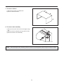
INSTALLATION
1. Steady, flat location
This microwave oven should be set on a steady, flat surface.
This microwave oven is designed for counter top use only.
2. Leave space behind and side
All air vents should be kept a clearance. If all vents are covered during operation, the oven may overheat and, eventually,
cause failure.
3. Away from radio, and TV sets
Poor television reception and radio interference may result if the oven is located close to a TV, radio, antenna, or feeder
and so on. Position the oven as far from them as possible.
4. Away from heating appliances and water taps
Keep the oven away from hot air, steam and splash when choosing a place to position it, or the insulation might be
adversely affected and breakdowns occur.
5. Power supply
• Check your local power source.
This microwave oven requires a current of approximately 6 amperes, 230 Volts, 50 Hz.
• Power supply cord is about 0.8 meters long.
• Used the voltage must be the same as specified on this oven. Using a higher voltage may result in a fire or other
accident causing oven damage. Using low voltage will cause slow cooking. We are not responsible for damage
resulting from use of this oven with a voltage of ampere fuse other than those specified.
• This appliance is supplied with cable of special type, which, if damaged, must be repaired with cable of same type.
Such a cable can be purchased from DAEWOO and must be installed by a qualified person.
6. Examine the oven after unpacking for any damage such as:
A misaligned door, broken door or a dent in cavity.
If any of the above are visible, DO NOT INSTALL, and notify dealer immediately.
7. Do not operate the oven if it is colder than room temperature
(This may occur during delivery in cold weather.) Allow the oven to become room temperature before operating.
EARTHING INSTRUCTIONS
This appliance must be earthed. In the event of an electrical short circuit, earthing reduces the risk of the electric shock
by providing an escape wire for the electric current. This appliance is equipped with a cord having a earthing plug. The
plug must be plugged into an outlet that is properly installed and earthed.
WARNING
Improper use of the earthing plug can result in a risk of electric shock. Consult a qualified electrician or service-man if
the earthing instructions are not completely understood, or if doubt exists as to whether the appliance is properly
earthed, and either : If it is necessary to use an extension cord, use only a 3-wire extension cord that has a 3-blade
earthing plug, and a 3-slot receptacle that will accept the plug on the appliance. The marked rating of the extension
cord should be equal to or greater than the electrical rating of the appliance, or DO NOT USE an extension cord.
6
OPERATIONS AND FUNCTIONS
1. Connect the mains lead to an electrical outlet.
2. After placing the food in a suitable container, open the oven
door and put it on the glass tray. The glass tray must always be
in place during cooking.
3. Close the door securely.
4. Choose cooking power level by setting V.P.C knob to the
desired position. Refer to cookbook for recommended power
levels.
5. Determine cooking time. Consult cookbook for recipe timing.
Oven light turns on and cooling fan starts to operate. Microwave
cooking starts.
6. You may open the door while the oven is operating. As soon as
the door is opened, the safety mechanisms stop the generation
of microwave power and the operation of cooking timer.
If you wish to change the time during cooking, simply adjust the
timer to the desired time.
7. When the timer reaches zero, a bell will ring and the unit will turn
off. Oven light turns off. If additional cooking time is needed and
the door is closed, the oven will automatically start when the
timer is reset.
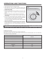
NOTE
When setting timer for less than 10
minutes, turn the timer past 10 minutes
and then return to the correct timer setting.
0
min
1
2
35
3
30
4
25
5
20
15
6
10
9
8
7
Make sure the oven is properly installed and plugged into the electrical outlet.
Variable power cooking
ON and OFF cycle time of mechanical V.P.C switch is 30 seconds.
When the V.P.C knob is set to the desired position and timer knob to the desired position, the V.P.C switch has a
cycle (ON/OFF time(sec.)) listed below.
Variable power setting
Approximate Percentage
Power level
of Power
HIGH
100%
MEDIUM HIGH
94%
MEDIUM
77%
LOW STAGE
55%
DEFROST
44%
HEAT
33%
GENTLE HEATING
17%
7
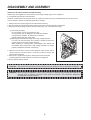
DISASSEMBLY AND ASSEMBLY
Cautions to be observed when trouble shooting.
Unlike many other appliances, the microwave oven is high-voltage, high-current equipment.
It is completely safe during normal operation.
However, carelessness in servicing the oven can result in an electric shock or possible danger from a short circuit.
You are asked to observe the following precautions carefully.
1. Always remove the power plug from the outlet before servicing.
2. Use an insulated screwdriver and ware rubber gloves when servicing the high voltage side.
3. Discharge the high voltage capacitor before touching any oven components or wiring.
(1) Check the grounding.
Do not operate on a two-wire extension cord.
The microwave oven is designed to be used while earthed.
It is imperative, therefore, to make sure it is earthed
properly before beginning repair work.
(2) Warning about the electric charge in the high voltage capacitor.
For about 30 seconds after the operation stopped and electric
charge remains in the high voltage capacitor.
When replacing or checking parts, short between oven chassis and
the negative high terminal of the high voltage capacitor by using a
properly insulated screwdriver to discharge.
4. When the fuse is blown out due to the operation of the monitor switch;
replace primary interlock switch, secondary interlock switch and
interlock monitor switch.
5. After repair or replacement of parts, make sure that the screws are
properly tightened, and all electrical connections are tightened.
6. Do not operate without cabinet.
SHORT
CAUTION : Service personnel should remove their watches whenever working close to or replacing the magnetron.
WARNING : When servicing the appliance, need a care of touching or replacing high potential parts because of
electrical shock or exposing microwave. These parts are as follows - HV Transformer, Magnetron,
HV Capacitor, HV Diode, HV fuse.
8
1. To remove cabinet
1) Remove four screws on cabinet back.
2) Pull the cabinet backward.
2. To remove door assembly
1) Remove two screws which secure the stopper hinge
top.
2) Remove the door assembly from top plate of cavity.
3) Reverse the above for reassembly.
NOTE : After replacing the door assembly, perform a check of correct alignment with the hinge and cavity front plate.
9
3. To remove door parts.
A06
A05
A04
A03
A02
A01
A07
A08
DOOR ASSEMBLY : 3511730190
REF No.
PART CODE
PART NAME
DESCRIPTION
A00
3511730190
DOOR AS
KOR-6L7B3S
1
A01
3512211140
FRAME DOOR
HIPS SG-970, HG-1760H
1
A02
3517007300
BARRIER SCREEN *O
PET T0.125
1
A03
3515204120
STOPPER HINGE *T AS
KOR-6L0B1A
1
A04
3511706130
DOOR PAINTING AS
KOR-6L0B1A
1
A05
3517003700
BARRIER SCREEN *I
PE T0.1
1
A06
3512302700
GASKET DOOR
PP
1
A07
3513100700
HOOK
POM
1
A08
3515101300
SPRING HOOK
PW1
1
1) Remove the gasket door from the door painting as.
2) Remove the barrier screen inner from the door painting as.
3) Remove the frame door from the door painting as.
4) Remove the stopper hinge top as from the door painting as.
5) Remove the spring hook and the hook from the door painting as.
6) Remove the barrier screen outer from the frame door.
7) Reverse the above steps for reassembly.
10
Q’TY
REMARK
4. Method to reduce the gap between the door seal and the oven front surface.
(1) To reduce gap located on part ‘A’
• Loosen two screws on the stopper hinge top, and then
push the door to contact the door seal to the oven front
surface.
• Tighten two screws.
(2) To reduce gap located on part ‘B’
• Loosen two screws on the stopper hinge under, and then
push the door to contact the door seal to the oven front
surface.
• Tighten two screws.
(3) To reduce gap located on part ‘C’
• Loosen the screw on the interlock switch assembly located
the top of the oven body.
• Draw the interlock switch assembly inward as possible to
engage with the hook on the door bottom.
• Tighten a screw.
(4) To reduce gap located on part ‘D’
• Loosen the screw on the interlock switch assembly located
the bottom of the oven body.
NOTE : A small gap may be acceptable if the microwave leakage does not exceed 4mW/cm2.
11
5. To remove control panel parts.
B06
B04
B05
B03
B01
B02
B07
B08
B09
B10
C/PANEL ASSEMBLY :
3516743110
B11
B12
REF No.
PART CODE
PART NAME
DESCRIPTION
QíTY
B00
3513412340
KNOB VPC
SG-0760D, SG-175
1
B01
3513412350
KNOB
SG-0760D, SG-175
1
B03
3516740390
CONTROL PANEL
HIPS SG-970, HG-1760H
1
B04
3517400510
COUPLER VPC KNOB
POM
1
B05
7122401211
SCREW TAPPING
T2S TRS 4*12 MFZN
1
B06
3518570400
SWITCH S/A RELAY
DWSR-1
1
B07
7122401211
SCREW TAPPING
T2S TRS 4*12 MFZN
2
B08
3518206600
TIMER
VFD35M106IIE DY2
1
B09
3515101600
SPRING FLAT
SUS 301 T0.5
1
B10
3513702700
LEVER DOOR OPEN
PP
1
B11
441G430171
SPRING BUTTON
SWP DIA. 0.7
1
B12
3516917720
BUTTON DOOR OPEN
SG-0760D, SG-175
1
1) Remove the screw which secure the control panel and draw forward the control panel assembly.
2) Remove two screws which secure the timer assembly.
3) Pull out the timer assembly from the control panel.
4) Pull out the timer knob from the timer.
5) Remove the screw which secure the coupler.
6) Pull out the coupler and V.P.C knob from the control panel.
7) Reverse the above steps for reassembly.
12
REMARK
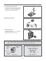
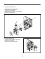
6. To remove high voltage capacitor.
1) Remove the screw which secure the grounding ring
terminal of the H.V. diode and the capacitor holder.
2) Remove the H.V. diode from the capacitor holder.
3) Reverse the above steps for reassembly.
◆ High voltage circuit wiring
7. To remove magnetron.
1) Remove three screws which secure the magnetron.
2) Remove the magnetron.
3) Reverse the above steps for reassembly.
NOTE : Never install the magnetron without the metallic gasket plate which is packed with each magnetron to
prevent microwave leakage. Whenever repair work is carried out on magnetron, check the microwave
leakage. It shall not exceed 4mW/cm2 for a fully assembled oven with door normally closed.
Metallic
gasket
plate
Wave guide Magnetron antenna
Magnetron
antenna
Cooling fin
Filament
terminal
<MAGNETRON>
Metallic gasket plate
13
8. To remove wind guide assembly.
1) Remove the screw for earthing.
2) Remove the noise filter from the wind guide.
3) Remove the screw which secure the wind guide assembly.
4) Draw forward the wind guide assembly.
5) Pull the fan from the motor shaft.
6) Remove two screws which secure the motor shaded pole.
7) Remove the motor shaded pole.
8) Reverse the above steps for reassembly.
9. To remove H.V.transformer.
1) Remove four screws holding the H.V.transformer.
2) Remove the H.V.transformer.
3) Reverse the above steps for reassembly.
14
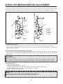
INTERLOCK MECHANISM AND ADJUSTMENT
The door lock mechanism is a device which has been specially designed to completely eliminate microwave radiation when
the door is opened during operation, and thus to perfectly prevent the danger resulting from the leakage of microwave.
Primary
interlock
switch
Button
WH/RD
RD
Hook
WH: WHITE
BK: BLACK
RD: RED
BL: BLUE
GN: GREEN
GY: GRAY
BK/BL
Monitor
interlock
switch
WH
BK/WH
Lock
lever
Secondary
intcrlock
switch
Mounting
screw
(1) Primary interlock switch
When the door is closed, the hook locks the oven door. If the door is not closed properly, the oven will not operate.
When the door is closed, the hook pushes the button of the microswitch. Then the button of the primary interlock switch
bring it under ON condition.
(2) Secondary interlock switch and interlock monitor switch
When the door is closed, the hook pushes the lock lever downward. The lock lever presses the button of the interlock
monitor switch to bring it under NO condition and presses the button of the secondary interlock switch to bring it under
ON condition.
ADJUSTMENT :
Interlock monitor switch
When the door is closed, the interlock monitor switch should be "OFF" condition before other switches are "ON" condition.
When the door is opened, the interlock monitor switch should be "ON" condition after other switches are "OFF" condition.
(3) Adjustment steps
a) Loosen the mounting screw.
b) Adjust interlock switch assembly position.
Actuation distance of primary and secondary interlock switch shall be adjusted almost 0.7mm.
c) Make sure that lock lever moves smoothly after adjustment is completed.
d) Tighten completely a mounting screw.
NOTE :
Microwave emission test should be performed after adjusting interlock mechanism.
If the microwave emission exceed 4mW/cm2, readjust interlock mechanism.
15
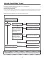
TROUBLESHOOTING GUIDE
Following the procedure below to check if the oven is defective or not.
1. Check grounding before trouble checking.
2. Be careful of the high voltage circuit.
3. Discharge the high voltage capacitor.
4. When checking the continuity of the switches, fuse or high voltage transformer, disconnect one lead wire from these parts
and check continuity with the AC plug removed. To do otherwise may result in a false reading or damage to your meter.
(TROUBLE 1) Oven does not operate at all ; any inputs can not be accepted.
Does the fan motor work when you
shut the door and turn the timer?
NO
Does the
fuse blow?
YES
Check continuity of interlock
monitor switch with door shut.
NO
Continuity
Replace primary, secondary interlock
switch and interlock monitor switch.
(NOTE1)
NO
NO
Replace fuse and check
continuity of both interlock
switch's contact and monitor
switch's contact with door
partially open until monitor
switch contact.
Replace primary, secondary interlock
switch and interlock monitor switch.
(NOTE1)
Both continuity
Disconnect one side of the
lead wire connected from
transformer to the high
voltage capacitor, and operate
oven.
Fuse again
If outlet has proper voltage, check
continuity of power supply cord.
Normal
Replace high voltage capacitor.
Replace high voltage transformer
NO Continuity
Replace power supply cord.
NOTE1 : All these switches must be replaced at the same time, please refer to “Interlock Mechanism And
Adjustment”
16
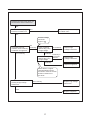
Does the fan motor work when you
shut the door and turn the timer?
YES
Does the oven lamp light?
Does the turntable turn?
NO
Replace or repair oven lamp,
turntable motor.
YES
Normal reading
should be
approx. 0
If microwave do not
oscillate, check continuity
of filament of magnetron.
NO
Continuity
Check continuity
filament tap (3.3V)
of high voltage.
No Continuity
Replace high
Voltage transformer
Continuity
Poor continuity
Check continuity
filament tap (3.3V)
of high voltage.
Continuity in
the reverse
direction.
Replace high
Voltage transformer
Continuity
Replace magnetron
Meter with 6V or higher
voltage batteries should
be used to check the normal
direction resistance of
the diode
Check the isolation of filament
winding of high voltage
transformer.
NO Continuity
Replace high voltage
transformer.
Good
Replace magnetron
17
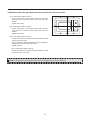
MEASUREMENT AND TEST
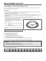
1. MEASUREMENT OF THE MICROWAVE POWER OUTPUT
Microwave output power can be checked by indirectly measuring the temperature rise of a certain amount of water
exposed to the microwave as directed below.
PROCEDURE
1. A cylindrical container of borosilicate glass is used for the test. It has a maximum thickness of 3mm, an external
diameter of approximately 190mm and a height of approximately 90mm.
The mass of the container is determined.
2. At the start of the test, the oven and the empty container are at ambient temperature. Water having an initial
temperature of 10˚C ± 1˚C is used for the test. The water temperature is measured immediately before it is poured
into the container.
3. A quantity of 1000g ± 5g of water is added to the container and its actual mass obtained.
The container is then immediately placed in the centre of the oven shelf, which is in its lowest normal position.
The oven is operated and the time for the water
temperature to attain 20˚C ± 2˚C is measured. The oven
is then switched off and the final water temperature is
measured within 60s.
NOTE 1 - The water stirred is before its temperature is
measured.
NOTE 2 - Stirring and measuring devices are to have a
low heat capacity.
4. The microwave power output is calculated from the
formula
P = {4,187 • mw(T2-T1) + 0.55 • mc (T2-T0)}/t
where
P is the microwave power output, in watts ;
mw is the mass of the water, in grams ;
mc is the mass of the container, in grams ;
T0 is ambient temperature, in degrees Celsius ;
T1 is the initial temperature of the water, in degree Celsius ;
T2 is the final temperature of the water, in degrees Celsius ;
t
is the heating time, in seconds, excluding the magnetron filament heating-up time.
✻ The microwave power output is stated in watts, rounded off to the nearest 50W
CAUTION
1. Water load should be measured exactly to 1 liter.
2. Input power voltage should be exactly specified voltage (Refer to SPECIFICATIONS).
3. Ambient temperature should be 20 ± 2°C (68 ± 3.6°F)
✻ Heating time for power output: (T2 = T0)
A (second)
70
64
60
56
52
49
47
44
42
40
38
B (W)
600
650
700
750
800
850
900
950
1000
1050
1100
18
2. MICROWAVE RADIATION TEST
CAUTION
1. Make sure to check the microwave leakage before and after repair of adjustment.
2. Always start measuring of an unknown field to assure safety for operating personnel from microwave energy.
3. Do not place your hands into any suspected microwave radiation field unless the safe density level is known.
4. Care should be taken not to place the eyes in direct line with the source of microwave energy.
5. Slowly approach the unit under test until the radiometer reads an appreciable microwave leakage from the
unit under the test.
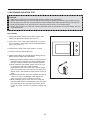
PROCEDURE
1. Prepare Microwave Energy Survey Meter, 600cc glass
beaker, and glass thermometer 100°C (212°F).
2. Pour 275cc ± 15cc of tap water initially at 20 ± 5°C (68 ±
9°F) in the 600 cc glass beaker with an inside diameter of
approx. 95 mm(3.7 in.).
3. Place it at the center of the tray and set it in a cavity.
4. Close the door and operate the oven.
5. Measure the leakage by using Microwave Energy Survey
Meter with dual ranges, set to 2450MHz.
1) Measured radiation leakage must not exceed the value
prescribed below. Leakage for a fully assembled oven
with door normally closed must be less than 4mW/cm2.
2) When measuring the leakage, always use the 5 cm (2
in.) space cone with probe. Hold the probe
perpendicular to the cabinet and door. Place the space
cone of the probe on the door, cabinet, door seem, door
viewing screen, the exhaust air vents and the suction air
vents.
3) Measuring should be in a counter-clockwise direction at
a rate of 1 in./sec. If the leakage of the cabinet door
seem is unknown, move the probe more slowly.
4) When measuring near a corner of the door, keep the
probe perpendicular to the areas making sure the probe
end at the base of the cone does not get closer than 2
in. from any metal. If it does not, erroneous reading may
result.
19
3. COMPONENT TEST PROCEDURE
• High voltage is present at the high voltage terminal of the high voltage transformer during any cooking cycle.
• It is neither necessary nor advisable to attempt measurement of the high voltage.
• Before touching any oven components or wiring, always unplug the oven from its power source and discharge the
capacitor.
1. High voltage transformer
1) Remove connections from the transformer terminals and check continuity.
2) Normal readings should be as follows :
Secondary winding ... Approx. 191.4 Ω ±10% (700W) / 221.2 Ω ±10% (800W)
Filament winding ... Approx. 0 Ω
Primary winding ... Approx. 2.512 Ω (700W) / 2.237 Ω (800W)
2. High voltage capacitor
1) Check continuity of capacitor with meter on the highest OHM scale.
2) A normal capacitor will show continuity for a short time, and then indicate 10MΩonce the capacitor charged.
3) A shorted capacitor will show continuous continuity.
4) An open capacitor will show constant 10MΩ.
5) Resistance between each terminal and chassis should be infinite.
3. High voltage diode
1) Isolate the diode from the circuit by disconnecting the leads.
2) With the ohmmeter set on the highest resistance scale measure the resistance across the diode terminals.
Reverse the meter leads and again observe the resistance reading. Meter with 6V, 9V or higher voltage
batteries should be used to check the front-back resistance of the diode, otherwise an infinite resistance may be
read in both directions. A normal diode's resistance will be infinite in one direction and several hundred k Ωin the
other direction.
4. Magnetron
For complete magnetron diagnosis, refer to "Measurement of the Microwave Power Output." Continuity checks can
only indicate and open filament or a shorted magnetron. To diagnose for an open filament or a shorted magnetron,
1) Isolate magnetron from the circuit by disconnecting the leads.
2) A continuity check across magnetron filament terminals should indicate 0.1 Ωor less.
3) A continuity check between each filament terminal and magnetron case should read open.
5. Fuse
If the fuse in the primary and monitor switch circuit is blown when the door is opened, check the primary and
monitor switch before replacing the blown fuse. In case the fuse is blown by an improper switch operation, replace
the defective switch and fuse at the same time. Replace just the fuse if the switches operate normally.
6. Interlock switches
(1) You can test continuity of safety interlock and monitor switch by using ohmmeter.
(2) The switch operation is checked by zero/unlimited.
The meter should indicate zero resistance.
(3) The sequence of check is interlock monitor switch, primary and secondary interlock switches check.
20
WIRING DIAGRAM
21
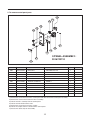
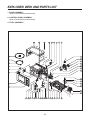
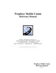
EXPLODED VIEW AND PARTS LIST
1. DOOR ASSEMBLY
Refer to Disassembly and assembly.
2. CONTROL PANEL ASSEMBLY
Refer to Disassembly and assembly.
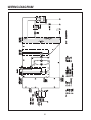
3. TOTAL ASSEMBLY
F01
F02
F03
F04
F05
F06
F07
F08
F09
F45
F10
F11
F44
F12
F43
F13
F14
F42
F15
F41
F16
F40
F17
F18
A00
F19
F20
B00
F21
F22
F39
F38
F37
F36
F35
F34
F33
F32
F31
F30 F04 F29 F28
22
F27
F26
F25
F24
F23
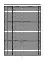
REF. NO
PART CODE
PART NAME
A00
B00
F01
F02
F03
F04
F05
F06
F07
F08
F09
F10
F11
F12
F13
F14
F15
F16
F17
F18
F19
F20
F21
F22
F23
F24
F25
F26
F27
F28
F29
F30
F31
F32
F33
F34
F35
F36
F37
F38
F39
F40
F41
F42
F43
3511730190
3516741190
3510808410
3516117410
3516004100
7122401211
7S312X40A1
35113AEQ0D
3516004100
7121300611
3518903800
3518608300
7121402511
3963514350
3512527600
3511800300
3518003710
7272400811
7S432X4081
3513003200
3518302201
3518401000
3518125500
3516003700
3510317500
7S312X40A1
3512100900
7S432X4081
3515201101
7S312X40A1
3512527800
3512720240
4415A17352
4415A66600
3513702600
3513818900
3513601600
7S312X40A1
3966031600
7S432X4081
3517400600
3511406220
3512517300
3514700710
3517203600
DOOR AS
CONTROL-PANEL AS
CABINET AS
CAVITY AS
SPECIAL SCREW
SCREW TAPPING
SCREW SPECIAL
CORD POWER AS
SPECIAL SCREW
SCREW TAPPING
THERMOSTAT
NOISE-FILTER
SCREW TAPPING
MOTOR SHADED POLE
GUIDE WIND
FAN
MAGNETRON
SCREW TAPTITE
SPECIAL SCREW
HOLDER HV CAPACITOR
CAPACITOR HV
DIODE HV AS
TRANS HV
SPECIAL SCREW
BASE
SCREW SPECIAL
FOOT
SPECIAL SCREW
STOPPER HINGE *U
SCREW SPECIAL
GUIDE AIR
HARNESS MAIN
SW MICRO
SW MICRO
LEVER LOCK
LOCK
LAMP
SCREW SPECIAL
MOTOR SYNCRO
SPECIAL SCREW
COUPLER
COVER WAVE GUIDE
GUIDE ROLLER
ROLLER
TRAY
DESCRIPTION
KOR-6L7B3S
KOR-6L753S
KOR-6L0B1A
KOR-6L0B1A
T1 TRS LR4 POLE 4*10 MFZN
T2S TRS 4X12 MFZN
T1 TRS 4*10 SE MFZN
3X0.75 70X70 100-RTML
T1 TRS LR4 POLE 4*10 MFZN
T2S PAN 3X6 MFZN
OFF:160 ON:115 V #187
DWLF-M12 B
T2S PAN 4X25 MFZN
230V 50HZ MW10CA-M04
PP
PP+30%GLASS
2M218HFL 6CF
TT3 TRS 4X8 MFZN
TT3 TRS 4X8 SE MFZN
SECC T0.5
2100VAC 0.98UF #187 75MM
ESJC13-12BX (CL01-12)
S1S57A
TT3 HEX 4X8 FLG MFZN
SBHG T0.5
T1 TRS 4*10 SE MFZN
PP DASF-130
TT3 TRS 4X8 SE MFZN
SCP-1 T2.5
T1 TRS 4*10 SE MFZN
SECC T0.5
KOR-6L053S
GSM-V1603A2 SPNO #187
GSM-V1602A2 SPNC #187
POM
PP FH44D GP-3152F
BL 240V 25W T25 C7A H187
T1 TRS 4*10 SE MFZN
220/240V 50/60HZ ST-16 MN73MQAD
TT3 TRS 4X8 SE MFZN
XAREC
PP J640A WHITE
PP 5113MF6 A353B
TEFLON
GLASS
23
Q'TY
1
1
1
1
4
2
2
1
1
2
1
1
2
1
1
1
1
3
1
1
1
1
1
4
1
5
2
1
1
1
1
1
1
1
1
1
1
1
1
2
1
1
1
3
1
DAEWOO ELECTRONICS CORP.
1-2, Jeo-dong 1(il)-ga, Jung-gu, Seoul, Korea
C.P.O. BOX 8003 SEOUL, KOREA
TELEX: DWELEC K28177-8
CABLE: “DAEWOOELEC”
S/M NO. : OR6L773S001
PRINTED DATE: Nov. 2011
ABOUT THIS MANUAL
VISION CREATIVE, INC.
서울 종로구 통의동
6 번지 이룸빌딩 4 층
담
당
이수용 님
MODEL
KOR-6L773S (S/M)
접
2011.11.22
수
1차
2차
일
정
3차
4차
5차
제
판
규
격
인
한
쇄
MEMO 총 25p
11.11.22-표지, 표지뒤, 3p, 4p, 5p, 7p, 10p, 11p, 12p, 19p, 22p,
23p_ 신규 12p
연락처
VISION 담 당
방 문 수
TEL: 730-0660 FAX: 730-3788