1
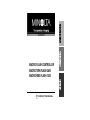
MACRO FLASH CONTROLLER
MACRO TWIN FLASH 2400
MACRO RING FLASH 1200
E INSTRUCTION MANUAL
CONTENTS
FOR PROPER AND SAFE USE
Names of Parts......................................................................................10
Please read and understand all warnings and cautions before using
this product.
BASIC OPERATION
Installing Batteries.................................................................................15
Checking Batteries ......................................................................16
Attaching and Removing the Controller.................................................17
Attaching the Twin Flash.......................................................................18
Attaching the Ring Flash.......................................................................23
Turning the Flash On and Off................................................................25
Film .....................................................................................................25
Basic Flash Mode..................................................................................26
Selecting Apertures - TTL Flash -................................................30
P Mode.........................................................................................33
DETAILED OPERATIONS
Manual Flash.........................................................................................35
Manual Flash (M) with Twin Flash ..............................................35
Manual Flash (M) with Ring Flash...............................................37
Manual Flash - Selecting Apertures and Power Levels..............38
Test Flash .............................................................................................44
Modeling Flash (Twin Flash Only).........................................................45
Wide Angle Adapter (Twin Flash Only)..................................................46
Diffuser (Twin Flash Only).....................................................................48
Focus Lamps (Ring Flash Only)............................................................51
Custom Functions..................................................................................52
APPENDIX
Examples of Twin Flash Photography...................................................56
Examples of Ring Flash Photography...................................................59
Aperture Range Graphs - Twin Flash....................................................60
Aperture Range Graphs - Ring Flash....................................................62
Compatibility .........................................................................................64
Care and Storage..................................................................................66
Specifications.........................................................................................68
2
WARNING
• Do not put your finger or metalic objects into the cord sockets on
the controller. Be careful not to let moisture such as rain enter the
socket(s). It may cause an electric shock. Attach the protective
socket caps when not in use.
• When unplugging the cord, do not pull on the cord. Hold the plug
when removing.
• Do not damage, twist, modify, or heat the cord. A damaged cord
may cause damage or injury through fire or electric shock.
Using batteries improperly can cause them to leak harmful solutions, overheat, or explode which may damage property or cause
personal injury. Do not ignore the following warnings.
• Only use the batteries specified in this instruction manual.
• Do not install the batteries with the polarity (+/–) reversed.
• Do not use batteries which show wear or damage.
• Do not expose batteries to fire, high temperatures, water, or moisture.
• Do not attempt to short or disassemble batteries.
• Do not store batteries near or in metallic products.
• Do not mix batteries of different types, brands, or ages; rechargeable batteries should be charged together, so that the battery
power is equal. Do not attempt to recharge akaline or lithium batteries.
• Do not use leaking batteries. If fluid from the batteries enters your
eye, immediately rinse the eye with plenty of fresh water and contact a doctor. If fluid from the batteries makes contact with your
skin or clothing, wash the area thoroughly with water.
• Tape over lithium battery contacts to avoid short-circuiting during
disposal; always follow local regulations for battery disposal.
3
FOR PROPER AND SAFE USE
WARNING
• Do not disassemble this product. Electric shock may cause injury
if a high voltage circuit inside the product is touched. Take the
product to a Minolta Service Facility when repairs are required.
• Immediately remove the batteries and discontinue use if the flash
or the controller is dropped or subjected to an impact in which the
interior, especially the flash unit, is exposed. The flash has a high
voltage circuit which may cause an electric shock resulting in
injury. The continued use of a damaged product or part may cause
injuries.
• Keep batteries or small parts that could be swallowed away from
infants. Contact a doctor immediately if an object is swallowed.
• Store this product out of reach of children. Be careful when
around children, not to harm them with the product or parts.
• Do not fire the flash directly into the eyes. It may damage eyesight. When taking close-ups of the facial area, subject’s eyes
should be protected.
• Do not fire the flash at vehicle operators. It may cause a distraction or temporary blindness which may lead to an accident.
• Do not use the product near inflammable gases or liquids such as
gasoline, benzine, or paint thinner. Do not use inflammable products such as alcohol, benzine, or paint thinner to clean the product. The use of inflammable cleaners and solvents may cause an
explosion or fire.
• If the product emits a strange odor, heat, or smoke, discontinue
use. Immediately remove the batteries taking care not to burn
yourself, as batteries become hot with use. The continued use of a
damaged product or part may cause injuries.
• Take the product to a Minolta Service Facility when repairs are
required.
4
CAUTION
• Do not use or store the product in a hot or humid environment
such as the glove compartment or trunk of a car. It may damage
the product and batteries which may result in burns or injuries
caused by heat, fire, explosion, or leaking battery fluid.
• If batteries are leaking, discontinue use of the product.
• Do not fire the flash while it is in contact with people or objects.
The flash unit discharges a large amount of energy which may
cause burns.
• Burns may result if the batteries are removed immediately after
prolonged or heavy flash use. Wait for the batteries to cool.
5
Thank you for purchasing this Minolta product. Please read this
manual thoroughly before using the macro flash or ring flash. We
hope that you will continue to be satisfied by our products.
These products are designed and manufactured for use with
Minolta Maxxum/Dynax series cameras and some Minolta digital
cameras. Performance when used with cameras from other manufacturers cannot be guaranteed. Minolta takes no responsibility
for accidents or malfunctions due to use with such cameras.
This device complies with Part 15 of the FCC Rules. Operation is
subject to the following two conditions: (1) This device may not cause
harmful interference, and (2) this device must accept any interference
received, including interference that may cause undesired operation.
Changes or modifications not approved by the party responsible for
compliance could void the user's authority to operate the equipment.
This equipment has been tested and found to comply with the limits for
a Class B digital device, pursuant to Part 15 of the FCC Rules. These
limits are designed to provide reasonable protection against harmful
interference in a residential installation. This equipment generates, uses
and can radiate radio frequency energy and, if not installed and used in
accordance with the instructions, may cause harmful interference to
radio communications.
However, there is no guarantee that interference will not occur in a
particular installation. If this equipment does cause harmful interference
to radio or television reception, which can be determined by turning the
equipment off and on, the user is encouraged to try to correct the
interference by one or more of the following measures:
• Reorient or relocate the receiving antenna.
• Increase the separation between the equipment and the receiver.
• Connect the equipment to an outlet on a circuit different from that to
which the receiver is connected.
• Consult the dealer or an experienced radio/TV technician for help.
This Class B digital apparatus complies with Canadian ICES-003.
The AC Adapter for this Macro Flash Controller is available only in
Japan. The use of an AC Adapter other than the specified unit can
permanently damage the flash and cause heat or fire.
The information in this manual is relevant for products introduced
before February 2001. Contact the nearest authorized Minolta
Service Facility to obtain information for products released after
this date.
6
This mark certifies that these products meets the
requirements of the EU (European Union) concerning
interference causing equipment regulations. CE stands for
conformité Européenne (European conformity).
7
MACRO FLASH OPTIONS
There are two types of lighting available; twin flash and ring flash.
Choose one, depending on your subject.
Ring Flash (4 flashtubes)
Macro Flash Controller
Twin Flash (2 flashtubes)
Macro Ring Flash 1200
Macro Flash Controller
Macro Twin Flash 2400
(Includes two units)
Use the optional Macro Ring Flash 1200 with the Macro Flash
Controller. Used for photographing small subjects in fine detail and
for scientific applications.
A wide choice of lighting variations is possible when the Macro Twin
Flash 2400 is used with the Macro Flash Controller. Suitable for
photographing flowers, insects, and small objects.
8
• The Macro Ring Flash 1200 is identical to that provided in the
Macro Flash 1200AF set. If you already have the Macro Flash
1200AF set, it is only necessary to purchase the Macro Flash
Controller.
• Each part may be purchased separately.
• The Macro Twin Flash 2400 cannot be used with the AF Macro
Zoom 3X-1X f/1.7-2.8 lens.
• Twin flash and the ring flash cannot be used together. When both
are connected, only the twin flash will fire.
9
NAMES OF PARTS
Macro Flash Controller MFC-1000
Control Panel
For information on specific parts, refer to the page numbers shown in
parenthesis.
Manual-flash-control dial
(Twin flash B) (36)
Manual-flash-control dial
(Twin flash A and Ring flash) (36, 37)
Reel-attachment
points (21)
Ring-flash-cord
release button (24)
Ring-flash-cord
socket (24)*
Twin-flash-cord socket
(Twin flash B )(19) *
Twin-flash-cord
release button (19)
Twin flash A
lamp (28)
Custom lamp (54)
Twin flash B
lamp (28)
TTL lamp (35)
Auto lamp (33)
Twin-flash-cord socket
(Twin flash A)(19) *
M (manual-flashcontrol) lamp (35)
Flash-on lamp
(25)
Flash-off lamp
(25)
Test-flash lamp
(44)
Flash-ready
lamp (29)
Modeling-flash
lamp (45)
DC terminal
Mounting-foot-release
button (17)
Mounting foot (17)
Flash on/off
button (25)
A-B / Lamp button
(Twin-flash A-B selection/ focus-lamp button)
(28, 51)
Test button
(Test/modeling flash
button) (44, 45)
TTL/M/Test button
(TTL/M/Test/Modeling flash
mode button )(35, 37)
Control panel (11)
Low-battery lamp (16)
Battery-chamber
door (15)
* Do not touch.
10
11
NAMES OF PARTS
Macro Twin Flash 2400
Macro Ring Flash 1200
Twin Flash Unit T-2400
(2 included)
Ring Flash Unit R-1200
Holder
Flashtube
Shoe
Focus lamps (51)
Flashtubes
Lighting-selector
switches (28)
Release tabs
Release
tabs
Connecting
cord
Plug
Connecting
cord
Plug (24)
Clip
Adapter rings ø49mm, ø55mm
Arm (2 included) (20)
Adapter rings ø49mm, ø55mm
Wide-angle adapter
(2 included) (46)
12
Diffuser (2 included) (48)
Cord reel
(2 included) (21)
13
INSTALLING BATTERIES
BASIC OPERATION
The Macro flash controller MFC-1000 may be powered by:
• Four AA-size alkaline batteries
• Four AA-size lithium batteries
• Four AA-size rechargeable nickel-metal hydride (Ni-MH) batteries
Always ensure that rechargeable nickel-metal hydride batteries are
charged in the proper charging unit.
1. Open the battery-chamber door as shown.
2. Insert the batteries according
to the diagram in the battery
chamber.
3. Close the battery-chamber
door.
• The indicator lamps on the control
panel should light. If not, press the
flash on/off button.
14
15
INSTALLING BATTERIES
ATTACHING AND REMOVING CONTROLLER
Checking Batteries
Attaching To The Camera
The
lamp on the control panel glows or blinks when the batteries are low.
When glowing; Power is low. The batteries will need to be replaced soon.
When blinking; Insert new batteries.
Flash cannot be used.
Push the mounting foot firmly
onto the camera until it stops.
• The controller locks in place automatically.
• If the camera’s built-in flash is raised,
lower it before attaching the controller.
Removing From The Camera
While pressing the mounting-foot
release button
, remove the
controller .
• Check the orientation of the batteries if nothing appears when the controller’s flash on/off button is pressed.
16
17
ATTACHING THE TWIN FLASH
1. Screw the appropriate adapter
ring onto the lens.
• 49mm and 55mm diameter adapters
are provided.
• If using the AF 200mm f/4 Macro Apo
G lens, a 72mm adapter is needed,
which can be be purchased separately (p. 64).
2. While pressing the tabs on
both sides of the holder, place
the holder over the adapter,
then release both tabs.
3. Remove the protective socket
caps.
• For safe-kepping, place the cap(s) in
the case. Replace caps after use.
5. Insert the twin-flash plug into
the twin-flash-cord socket on
the controller.
When removing the plug, press the twinflash-cord release button and pull plug
straight out of the socket.
• Do not remove the plug by pulling on the
cord.
6. Adjust position of flashtubes as
desired.
A twin flash unit can be attached to
any of the holder ’s 4 shoes.
Flashtube can be tilted.
4. Place a twin flash unit into one
of the holder ’s shoes.
• Use of an arm is also possible (p. 20).
Holder can be rotated.
Press the release tabs
when removing or rotating
the holder.
18
Continued on next page
19
ATTACHING THE TWIN FLASH
You can use an arm to position the flash
unit away from the lens.
Attach the arm by sliding its base into
one of the four shoes on the holder.
The cord reel can be attached to the side of the controller to take
up excessive cord slack.
When attaching it to the controller, orient
the reel with the Minolta logo in a
readable horizontal position, and place
the top of the reel’s center cut-out over
the top of the three protruding pins on
the controller. Next, rotate the reel down
until the reel’s center cut-out clicks into
place over the lower protruding pins.
The arm can be set
at either of two
lengths.
The angle of the arm can be
adjusted to either of two
positions. The arm is secured in
each position by a double click
stop.
60° position
Secure the excess cord
by wrapping it around the
reel and using the outer
cut-outs as shown in the
illustration.
To remove the reel, rotate the bottom of
the reel away from the controller and
remove.
90° position
• In order to prevent breakage, it is possible to move the arm past the
two correct stop positions. However, to prevent excessive wear, use
only in the correct positions.
• It is also possible to attach the two arms in tandem, but this is not recommended as the excesive length could result in breakage.
20
21
ATTACHING THE TWIN FLASH
ATTACHING THE RING FLASH
1. Screw the appropriate adapter
ring onto the lens.
• 49mm and 55mm diameter adapters
are provided.
• If using the AF 200mm f/4 Macro Apo
G lens, a 72mm adapter is needed,
which can be be purchased separately (p. 64).
The angle of flash coverage
will increase if you attach the
wide-angle adapter to the
flashtube (p. 46).
Strong shadows can be softened by
using the diffuser attached to the
flashtube. Always use the diffuser with
an arm (p. 48).
2. While pressing the tabs on
both sides of the ring flash,
place the ring flash over the
adapter, then release both
tabs.
• Attach the ring flash directly to the AF
Macro Zoom 3X-1X f/1.7-2.8 lens.
•
•
•
•
Do not allow the cord to get in front of the flashtube or lens.
Make sure the flashtube is pointing at the subject.
See page 56 for photographic examples.
If an arm is used when taking very close-ups with the AF Macro 50mm
f/2.8 lens, the subject may not receive sufficient lighting (p. 57).
• The AF Macro Zoom 3X-1X f1.7-2.8 lens can not be used with the
twin flash.
3. Remove the protective socket
cap.
• For safe-keeping, place cap in bag.
Replace cap after use.
Continued on next page
22
23
ATTACHING THE RING FLASH
4. Insert the ring-flash plug into
the ring-flash-cord socket on
the controller.
TURNING THE FLASH ON AND OFF/ FILM
ON/OFF
Turn the flash on by pressing the flash
on/off button.
When the flash turns on, the flash-on lamp
will glow.
• Press the release tabs when removing
the ring flash.
• Do not allow the cord to get in front of the
lens or ring flashtubes. Use the cord clip
to secure the cord.
With the flash on, pressing the flash on/off
button will turn the flash off and flash-off
lamp will glow.
• The lamp will go out after a little more than
10 seconds.
When removing the plug, press the ringflash-cord release button and pull plug
straight out of the socket.
• Do not remove the plug by pulling on the
cord.
• When the flash is attached and you operate your camera, power is
supplied automatically to the flash, and the lamp will glow. (auto power
on). Power is switched off and lamps go out automatically to save batteries when the camera or flash is not used for four minutes (auto
power off).
• Custom settings may be used to change the time of auto power off, or
to disable auto power off (p. 52).
• See page 59 for photographic examples.
Film
Do not use high-speed film (rating in excess of ISO 1000) with TTL
direct metering (TTLlamp will be on, see page 35). Use of such film
increases the exposure error.
• The low-speed film limit is the same as that for the films specified for
the camera. See the camera manual for details.
24
25
BASIC FLASH MODES
Camera’s exposure mode should be set to either A (aperture priority) mode*, or M (manual) mode**.
1. Turn camera on and set to A
mode or M mode.
Depth-of-field*** is quite shallow at close-up and macro ranges, so
focusing is very important. It is recommended that you use a macro
lens and select an aperture as small as practical to maximize the
depth-of-field.
In this section, the basic flash operation in A or M mode with TTL
metering (TTL lamp on) is described.
2. Turn the flash on by pressing
the flash on/off button. The
flash-on lamp will glow.
*A mode: In A mode, you select the aperture and the camera
automatically sets the shutter speed required for proper exposure.
**M mode: You can select both aperture or shutter speed. HSS (highapeed sync) is not possible.
***Depth-of-field: The range behind and in front of the subject that
appears sharp.
3. Focus your subject and check
the magnification ratio.
• The location of the magnification ratio
scale differs, depending on which
lens is used.
This part of the manual assumes that the user is using one of
the following cameras and macro lens.
Camera: A camera having A mode (aperture priority) or M mode
(manual).
Lens:
AF 50mm f/2.8 Macro
AF 50mm f/2.8 (D) Macro
AF 50mm f3.5 Macro
AF 100mm f/2.8 Macro
AF 100mm f/2.8 (D) Macro
AF 200mm f/4 Macro Apo G
AF Macro Zoom 3X-1X f/1.7-2.8
4. When using M mode, select a
shutter speed that is slower
than the camera’s sync speed.
5. Select an aperture. Refer to the
tables on pages 30 to 32.
If you use a camera other than one listed above, refer to P mode
flash section (p. 33). If using a different lens, see pages 60 and 62.
Continued on next page
26
27
BASIC FLASH MODES
6. Select the flash.
In the case of the twin flash, each
press of the A-B / lamp button causes
the selected flash units to go from
both A and B, then only A, and finally
only B.
B
A
Right flashtube
All flashtubes
As viewed from the rear
(control panel side), the A
flash is the one connected to
the left side socket, the B
flash to the right side.
The ring flash has four separate
flashtubes. These can be turned
on or off independently by using
the lighting-selector switches on
the back of the unit. When the
switch shows red, that flashtube is
on. When black, that flashtube is
off.
7. When the flash is charged,
press the shutter-release button to take the photo.
• The flash is charged when
is lit on
the rear of the unit, and
also
appears in the camera viewfinder.
When the correct exposure was
obtained for the photo just taken:
• The flash-ready lamp
blinks on the
control panel for two seconds.
•
blinks in the camera viewfinder.
• The photo will be under-exposed if taken before charging is complete.
• The use of a tripod or remote cord is recommended to reduce camera
shake.
• Camera-to-subject distance of less than 0.5m, and a magnification
ratio of more than 0.15X (greater than 1:7), are recommended to get
the best results from the macro flash units.
• When neither a twin flash or ring flash is attached, turn the controller
off. Otherwise proper exposure will not be obtained.
• The camera’s AF illuminator is blocked by the adapter ring or flash
and cannot be used for focusing.
• If you turn off the ring flash while it is connected to the controller,
press the flash on/off button on the controller. Proper exposure will not
be obtained if only the four lighting-selector switches on the ring flash
are turned off.
28
29
BASIC FLASH MODES
AF 100mm f/2.8 Macro (Lens aperture range: f/2.8 - f/32)
Selecting Apertures - TTL Flash • The tables beginning at the bottom of this page shows values when
ISO 100 film is used without the wide-angle adapter or diffuser. For
other ISO film speeds, or if you use the wide-angle adapter or diffuser,
adjust the aperture settings according to the tables on page 32.
• The aperture ranges given in the tables are calculated values; the
actual lens will have its own usable aperture range.
Example: Using an AF 50mm f/2.8 Macro lens with a pair of twin flash
units with no arm, at a magnification ratio of 1:1. The range of acceptable apertures is calculated to be from f/4 to f/90 (bold type in the
table). However, the actual range possible with this lens is f/4 to f/32.
• The following tables show data for certain lenses and magnification
ratios. For other lenses and magnification ratios, see pages 60 and
62.
Without arm
Arm (short)
60 ° position
Arm (long)
90 ° position
Ring Flash
1:1
1:1.5
1:2
1:3
1:4
4 ~ 90
2.8 ~ 64
2.4 ~ 54
1.7 ~ 38
1.4 ~ 32
1 ~ 22
2.8 ~ 64
5.6 ~ 128
4 ~ 90
2.8 ~ 64
2 ~ 45
1.4 ~ 32
1 ~ 22
3.5 ~ 76
8 ~ 180
5.6 ~ 128
4 ~ 90
2.8 ~ 64
2 ~ 45
1.4 ~ 32
3.5 ~ 76
5.6 ~ 128
4 ~ 90
4 ~ 90
2.8 ~ 64
2.4 ~ 54
1.7 ~ 38
2.4 ~ 54
4.5 ~ 108
3.5 ~ 76
4.5 ~ 180
3.5 ~ 76
2.8 ~ 64
2 ~ 45
2 ~ 45
Upper set of numbers is for two twin flash units.
Lower set is for one twin flash unit.
Ring flash is common for 1 ~ 4 tubes.
30
Without arm
Arm (short)
60 ° position
Arm (long)
90 ° position
Ring Flash
1:1
1:1.5
3.5 ~ 76
2.4 ~ 54
2 ~ 45
1.4 ~ 32
1.2 ~ 27
0.85 ~ 19
1.4 ~ 32
3.5 ~ 76
2.4 ~ 54
2.8 ~ 64
2 ~ 45
1.7 ~ 38
1.2 ~ 27
1.4 ~ 32
1:2
1:3
2.8 ~ 64 2.4 ~ 54
2 ~45
1.7 ~38
2.8 ~ 64 2.8 ~ 64
2 ~ 45
2 ~ 45
2 ~45
2 ~45
1.4 ~ 32 1.4 ~ 32
1.2 ~ 27 1 ~ 22
AF 200mm f/4 Macro Apo G (Lens aperture range: f/4 - f/32)
Magnification
ratio
Without arm
Arm (short)
60 ° position
Arm (long)
90 ° position
Ring Flash
AF 50mm f/2.8 Macro (Lens aperture range: f/2.8 - f/32)
AF 50mm f/3.5 Macro (Lens aperture range: f/3.5 - f/32)
Magnification
ratio
Magnification
ratio
1:1
1:1.5
1:2
2.8 ~ 64
2 ~ 45
2.8 ~ 64
2 ~ 45
2 ~ 45
1.4 ~ 32
1.7 ~ 38
2 ~ 45
1.4 ~ 32
2.8 ~ 64
2 ~ 45
2 ~ 45
1.4 ~ 32
1.2 ~ 27
1.7 ~ 38
1.2 ~ 27
2 ~ 45
1.4 ~ 32
1.7 ~ 38
1.2 ~ 27
1 ~ 22
AF Macro Zoom 3X-1X f/1.7-2.8 (Lens aperture range: 1X: f/5.6 54, 3X: f/6.7 - 64)
Magnification
ratio
Ring Flash
1X
3X
4.5 ~ 108
4 ~ 90
Upper set of numbers is for two twin flash units.
Lower set is for one twin flash unit.
Ring flash is common for 1 ~ 4 tubes.
31
BASIC FLASH MODES
When Using Film Other Than ISO 100, Or When Using the
Wide-Angle Adapter or Diffuser
An additional adjustment must be applied to the previous tables.
ISO 25
ISO 50
ISO 100
ISO 200
ISO 400
ISO 800
W/O Wide-angle
With Wide-angle
With Diffuser
adapter or Diffuser
adapter
(Exposure adjustment) (Exposure adjustment) (Exposure adjustment)
+2 Stop
+3.5 Stop
+4.5 Stop
+1 Stop
+2.5 Stop
+3.5 Stop
No change
+1.5 Stop
+2.5 Stop
–1 Stop
+0.5 Stop
+1.5 Stop
–2 Stop
–0.5 Stop
+0.5 Stop
–3 Stop
–1.5 Stop
–0.5 Stop
Using the diagram at the left, moving one step
vertically is equal to a full-stop change. Moving
one step diagonally, is equal to a half-stop
change.
Example: starting at f/8, if you decrease the
exposure by a full-stop, you get f/11. If you
increase by a half-stop, you get f/6.7.
P Mode
The procedure for P mode, including subject program selection, is
the same as that for A or M mode, except that the aperture is set
automatically.
• With some cameras, the flash will fire
automatically in P mode. In this case, the
auto lamp will glow and the flash may not
fire if the surrounding conditions are
bright.
• P mode flash program is designed for general subjects, not close-up
or macro subjects. If macro photos are taken, the depth-of field may
be very shallow. If the aperture selected by the camera is outside the
allowable range, the proper exposure can not be obtained (p. 30 - 32).
Example: using an AF 50mm f/2.8 Macro lens,
two twin flash units, no arm, magnification ratio of
1:1, and ISO 100 film. The calculated acceptable
aperture range is f/4 - f/90 (bold type in the table,
page 30). But with ISO 50 film and the diffuser,
using the chart above, you will see that you need
to increase the aperture by +3.5 stops. This
results in a calculated acceptable aperture range
of f/1.2 - f/27. However, because the actual aperture range for this particular lens is f/2.8 - f/32,
the usable range for satisfactorily results would
be f/2.8 - f/27.
32
33
MANUAL FLASH (M)
DETAILED
OPERATIONS
Normal TTL flash metering automatically
adjusts the flash intensity to provide the
proper exposure for the subject. Manual
flash provides a fixed flash intensity irrespective of the brightness of the subject
and the camera setting.
• In manual flash, the maximum flash power
is when the manual flash control is set to
1/1. Each step of the flash power level
corresponds to one aperture stop. For
example, changing the setting from 1/1 to
1/2, or from 1/32 to 1/64 decreases the
exposure by one stop.
• Manual flash operates in the camera’s M
(manual) mode only. In other modes, TTL
measuring is selected automatically.
• As manual flash is not affected by the
reflectivity of the subject, it is useful for
subjects with extremely high or low reflectivity.
TTL flash metering
Manual flash
Manual Flash With Twin Flash
1. Select the M mode on the camera.
2. Press the TTL/M/test button
(TTL/M/
/ ) until the M lamp
glows.
• Each time the button is pressed, the
flash modes will change (see next
page). For test firing and modeling,
see page 44 and 45.
34
35
MANUAL FLASH (M)
Manual Flash With Ring Flash
TTLflash
Test flash
Manual flash
Test flash
TTLflash
Modeling flash
1. Select the M mode on the camera.
2. Press the TTL/M/test button
(TTL/M/
/ ) until the M lamp
glows.
Manual flash
Modeling flash
• Each time the button is pressed, the
flash modes will change as follows:
(For test flash firing see page 44.)
3. Select shutter speed and aperture (p. 38).
4. Turn the appropriate manual-flash-control dial and select
the desired power level (p. 38).
A
B
When viewed from the rear
(control panel side), the
manual-flash-control dial for
twin flash A is on the left;
and that for twin flash B is
on the right. Any power level
setting between 1/1 ~ 1/64
can be selected.
TTL flash
Test flash
Manual flash
Test flash
3. Select shutter speed and aperture (p. 38).
4. Turn manual-flash-control dial and select the desired
power level (p. 38).
The manual-flash-control dial for the
ring flash is on the left side (this is the
same control dial used for the twin
flash A). Select any power lever
between 1/1 ~ 1/64.
• See the tables on page 38 to 43 for the aperture and power level
needed to obtain a proper exposure. The flash-ready lamp
will not
blink on the control panel after the photo is taken.
• The size of the step on the manual-flash-control dials can be changed
from full-stop increments to half-stop increments by adjusting the custom settings. See page 52.
For ring flash
Continued on next page
36
37
MANUAL FLASH (M)
• See the tables on pages 38 to 43 for the aperture and power level
needed to obtain a proper exposure. The flash-ready lamp
will not
blink on the control panel after the photo is taken.
• The size of the step on the manual-flash-control dials can be changed
from full-stop increments to half-stop increments by adjusting the custom settings. See page 52.
Selecting Apertures and Power Level - Manual Flash • The tables beginning on the next page show values for ISO 100
speed film without the wide-angle adapter or diffuser. For other ISO
film speeds, or for the use of the wide-angle adapter or diffuser, adjust
the aperture settings according to the table on page 43. When using
the twin flash, the data assumes that the power lever is the same for
both units. If they are set at different power levels, see page 42.
• The aperture values given in the tables are calculated values; the
actual lens will have its own usable aperture range.
Example: using an AF 50mm f/2.8 Macro lens with a pair of twin flash
units with no arm, power level of 1/1, and a magnification ratio of 1:1,
the aperture is calculated at f/90 (bold type in the table, page 39).
However, the smallest actual aperture possible with this lens is f/32.
Therefore, if you set the power level to 1/1, the picture will be overexposed. But, if you set the power level to 1/8, you will get a correct
exposure at f/32 (italic type in the table, page 39).
• These tables show the apertures where the proper exposure of the
illuminated area is obtained. Actual exposure varies according to the
subject’s shape or position. Test photographs or bracketing is recommended especially when the subject is illuminated from side or
behind.
• The following tables show data for certain lenses and magnification
ratios. For other lenses and magnification ratios, see pages 61 and
63.
38
AF 50mm f/2.8 Macro (Lens aperture range: f/2.8 - f/32)
AF 50mm f/3.5 Macro (Lens aperture range: f/3.5 - f/32)
Magnification Ratio
1:1
1:1.5
1:2
1:3
Power level
1/1
90 (64) 128 (90) 180 (128) 128 (90)
1/2
64 (45) 90 (64) 128 (90) 90 (64)
1/4
45 (32) 64 (45) 90 (64) 64 (45)
1/8
32 (22) 45 (32) 64 (45) 45 (32)
1/16
22 (16) 32 (22) 45 (32) 32 (22)
1/32
16 (11) 22 (16) 32 (22) 22 (16)
1/64
11 (8) 16 (11) 22 (16) 16 (11)
1/1
54 (38) 64 (45) 90 (64) 90 (64)
1/2
38 (27) 45 (32) 64 (45) 64 (45)
1/4
27 (19) 32 (22) 45 (32) 45 (32)
1/8
19 (13) 22 (16) 32 (22) 32 (22)
1/16
13 (9.5) 16 (11) 22 (16) 22 (16)
1/32
9.5 (6.7) 11 (8) 16 (11) 16 (11)
1/64
6.7 (4.5) 8 (5.6)
11 (8)
11 (8)
1/1
32 (22) 32 (22) 45 (32) 54 (38)
1/2
22 (16) 22 (16) 32 (22) 38 (27)
1/4
16 (11) 16 (11) 22 (16) 27 (19)
1/8
11 (8)
11 (8) 16 (11) 19 (13)
1/16
8 (5.6) 8 (5.6) 11 (8) 13 (9.5)
1/32
5.6 (4) 5.6 (4) 8 (5.6) 9.5 (6.7)
1/64
4 (2.8) 4 (2.8) 5.6 (4) 6.7 (4.5)
1/1
64
76
76
54
1/2
45
54
54
38
1/4
32
38
38
27
Ring flash
1/8
22
27
27
19
(1 ~ 4 lamps)
1/16
16
19
19
13
1/32
11
13
13
9.5
1/64
8
9.5
9.5
6.7
Use aperture values inside ( ) when only one twin flash unit is used.
1:4
108 (76)
76 (54)
54 (38)
38 (27)
27 (19)
19 (13)
13 (9.5)
108 (76)
76 (54)
54 (38)
38 (27)
27 (19)
19 (13)
13 (9.5)
64 (45)
45 (32)
32 (22)
22 (16)
16 (11)
11 (8)
8 (5.6)
45
32
22
16
11
8
5.6
39
MANUAL FLASH (M)
AF 100mm f/2.8 Macro (Lens aperture range: f/2.8 - f/32)
Magnification Ratio
1:1
1:1.5
1:2
1:3
Power level
1/1
76 (54) 76 (54) 64 (45) 54 (38)
1/2
54 (38) 54 (38) 45 (32) 38 (27)
1/4
38 (27) 38 (27) 32 (22) 27 (19)
1/8
27 (19) 27 (19) 22 (16) 19 (13)
1/16
19 (13) 19 (13) 16 (11) 13 (9.5)
1/32
13 (9.5) 13 (9.5) 11 (8) 9.5 (6.7)
1/64
9.5 (6.7) 9.5 (6.7) 8 (5.6) 6.7 (4.5)
1/1
45 (32) 64 (45) 64 (45) 64 (45)
1/2
32 (22) 45 (32) 45 (32) 45 (32)
1/4
22 (16) 32 (22) 32 (22) 32 (22)
1/8
16 (11) 22 (16) 22 (16) 22 (16)
1/16
11 (8) 16 (11) 16 (11) 16 (11)
1/32
8 (5.6)
11 (8)
11 (8)
11 (8)
1/64
5.6 (4) 8 (5.6) 8 (5.6) 8 (5.6)
1/1
27 (19) 38 (27) 45 (32) 45 (32)
1/2
19 (13) 27 (19) 32 (22) 32 (22)
1/4
13 (9.5) 19 (13) 22 (16) 22 (16)
1/8
9.5 (6.7) 13 (9.5) 16 (11) 16 (11)
1/16
6.7 (4.5) 9.5 (6.7) 11 (8)
11 (8)
1/32
4.5 (3.5) 6.7 (4.5) 8 (5.6) 8 (5.6)
1/64
3.5 (2.4) 4.5 (3.5) 5.6 (4) 5.6 (4)
1/1
32
32
27
22
1/2
22
22
19
16
1/4
16
16
13
11
Ring flash
1/8
11
11
9.5
8
(1 ~ 4 lamps)
1/16
8
8
6.7
5.6
1/32
5.6
5.6
4.5
4
1/64
4
4
3.5
2.8
Use aperture values inside ( ) when only one twin flash unit is used.
40
AF 200mm f/4 Macro Apo G (Lens aperture range: f/4 - f/32)
Magnification Ratio
1:1
1:1.5
1:2
Power level
1/1
64 (45) 45 (32) 38 (27)
1/2
45 (32) 32 (22) 27 (19)
1/4
32 (22) 22 (16) 19 (13)
1/8
22 (16) 16 (11) 13 (9.5)
1/16
16 (11) 11 (8) 9.5 (6.7)
1/32
11 (8)
8 (5.6) 6.7 (4.5)
1/64
8 (5.6) 5.6 (4) 4.5 (3.5)
1/1
64 (45) 64 (45) 45 (32)
1/2
45 (32) 45 (32) 32 (22)
1/4
32 (22) 32 (22) 22 (16)
1/8
22 (16) 22 (16) 16 (11)
1/16
16 (11) 16 (11) 11 (8)
1/32
11 (8)
11 (8)
8 (5.6)
1/64
8 (5.6) 8 (5.6) 5.6 (4)
1/1
45 (32) 45 (32) 38 (27)
1/2
32 (22) 32 (22) 27 (19)
1/4
22 (16) 22 (16) 19 (13)
1/8
16 (11) 16 (11) 13 (9.5)
1/16
11 (8)
11 (8) 9.5 (6.7)
1/32
8 (5.6) 8 (5.6) 6.7 (4.5)
1/64
5.6 (4) 5.6 (4) 4.5 (3.5)
1/1
38
27
22
1/2
27
19
16
1/4
19
13
11
Ring flash
1/8
13
9.5
8
(1 ~ 4 lamps)
1/16
9.5
6.7
5.6
1/32
6.7
4.5
4
1/64
4.5
3.5
2.8
Use aperture values inside ( ) when only one twin flash unit is used.
41
MANUAL FLASH (M)
AF Macro Zoom 3X-1X f/1.7-2.8 (Lens aperture range at 1X: f/5.6 - 54,
at 3X: f/6.7 - 64)
Magnification Ratio
Power level
1/1
1/2
1/4
Ring flash
1/8
(1 ~ 4 lamps)
1/16
1/32
1/64
1X
3X
108
76
54
38
27
19
13
90
64
45
32
22
16
11
The following adjustment must be made to the exposure when
using different film speeds or accesories.
ISO 25
ISO 50
ISO 100
ISO 200
ISO 400
ISO 800
When Twin Flash Units are at Different Power Level Settings
The values given in the preceding tables for the twin flashes,
assume that both twin flash units are set at the same flash level.
When they are set to different flash power levels, the aperture
needed for correct exposure can be calculated using the following
equasion:
Aperture* =
(A flash aperture) 2 + (B flash aperture) 2
Example: using an AF 100mm f/2.8 Macro lens with a pair of twin flash
units with no arm. “A” twin flash is set at a power level of 1/8, “B” twin
flash unit is set at 1/16, and the magnification ratio is 1:1 (bold type values in the table on page 40).
Aperture =
192 + 132 =
361 + 169 =
When Using Film Other Than ISO 100, Or When Using the
Wide-Angle Adapter or Diffuser
530
22
Therefore, in the above example, an aperture setting of f/22 will give
proper exposure.
W/O Wide-angle
With Wide-angle
With Diffuser
adapter or Diffuser
adapter
(Exposure adjustment) (Exposure adjustment) (Exposure adjustment)
+2 Stop
+3.5 Stop
+4.5 Stop
+1 Stop
+2.5 Stop
+3.5 Stop
No change
+1.5 Stop
+2.5 Stop
–1 Stop
+0.5 Stop
+1.5 Stop
–2 Stop
–0.5 Stop
+0.5 Stop
–3 Stop
–1.5 Stop
–0.5 Stop
Using the diagram at the left, moving one step
vertically is equal to a full-stop change. Moving
one step diagonally, is equal to a half-stop
change. Example: starting at f/8, if you decrease
the exposure by a full stop, you get f/11. If you
increase the exposure by a half stop, you get
f/6.7.
If you were using an AF 200mm f/4 Macro Apo G
lens, two twin flash units, no arm, a power level
of 1/4, magnification ratio of 1:1, and ISO 100
film, the calculated aperture would be f/32 (bold
type in the table on page 41). But with ISO 200
film and the diffuser, using the chart above, you
will see that you need to adjust the aperture by
+1.5 stops. The resulting aperture of f/19 is
required for a correct exposure.
* When both twin flash units are used.
42
43
TEST FLASH
MODELING FLASH (TWIN FLASH ONLY)
One test flash may be used before taking a photograph. Use testflash mode
when using a flash meter in manual-flash mode.
The modeling flash is used to check for shadows on the subject
before taking a photograph. The flash will fire for 2 seconds at a rate
of 40 flashes per second.
Check that the test-flash lamp
is on. Press the test button to fire
the test flash.
1. Press the TTL/M/Test button to
make the modeling-flash lamp
glow.
• With the modeling-flash lamp
confirm that either the TTL or M
mode is selected as desired.
• If the test-flash lamp
isn’t glowing,
press the TTL/M/Test button to make the
test-flash lamp glow.
• Each time the TTL/M/Test button is
pressed, the TTLand M lamp will change
- be sure to check that the appropriate
lamp is glowing. See page 36 (twin flash)
or page 37 (ring flash) for the display
sequence.
• With TTL flash metering, the test flash will fire at full power when the
test button is pressed.
• In manual flash mode, the test flash will fire at the selected power
level when the test button is pressed. When using a flash meter, use
the manual flash mode.
• If the modeling-flash lamp glows, the modeling flash will fire when the
test button is pressed. See page 45.
44
on,
2. Press the test button. The
modeling flash will fire.
• Do not release the shutter while the modeling flash is firing.
• The strength of the shadows will differ from the actual photograph.
• Shadows will be lighter when using the flash in bright areas or outdoors.
• When the ring flash is used, the modeling-flash lamp will not glow.
45
WIDE-ANGLE ADAPTER (TWIN FLASH ONLY)
• Remove the wide-angle adaptor while
holding its top tab.
With wide-angle adaptor
Without wide-angle adaptor
• The flash output is reduced when using the wide-angle adapter. See
page 32 for TTL flash metering, or 43 for manual flash metering.
The twin flash unit has a coverage of 60° horizontally, and 45° vertically (equivalent to a lens with a 35mm focal length). But by attaching the wide-angle adaptor, the angles will be increased to 78° horizontally and 60° vertically (equivalent to a lens with a 24mm focal
length).
While holding the wide-angle adapter by its top tab, press it
against the face of the twin flash unit until it clicks and is
securely mounted.
Place the adapter so that the
MINOLTA logo is readable.
Align the lower edge.
46
47
DIFFUSER (TWIN FLASH ONLY)
Place the four side tabs into each
slot on the side of the diffuser.
With diffuser
Assembled
With diffuser
Without diffuser
Without diffuser
Strong shadows can be softened by using the diffuser attached to
the flashtube. Always use the diffuser with an arm set at the 90 °
position. If the arm is set at the 60° position and used with a wide
angle lens, the diffuser may be show in the image.
• If it is difficult to assemble the diffuser, fold
it and try again.
• The diffuser should assemble easily. Do
not force or pull hard on the diffuser.
• Do not fold the diffuser inside out.
1. Prepare the diffuser for use.
Unclip the adapter
from the diffuser.
Slide tab through the slot
near the clip.
2. While holding the diffuser by its top tab, press it against
the face of the twin flash unit until it clicks and is securely mounted.
Align the lower edge.
This side cannot
be detached.
The dimple above the
slot should slide into
the hole in the tab.
48
49
DIFFUSER (TWIN FLASH ONLY)
FOCUS LAMPS (RING FLASH ONLY)
• The flash output is reduced when using the diffuser. See page 32 for
TTL flash metering, or page 43 for manual flash metering.
The ring flash has four focus lamps mounted near the flashtubes in
the lighting unit. These lamps make framing subjects easy and provide light for the camera’s autofocusing system.
• When removing, remove the diffuser while
holding its adapter’s top tab.
• When folding the diffuser, pull the tab off
the dimple as shown. The tab can now be
easily removed.
• When storing, refold the diffuser, and
secure it by clipping the adapter to the diffuser.
50
Press the A-B / lamp button on
the back of the controller.
• After the A-B / lamp button is pressed,
the focus lamps will turn on for a little
more than 10 seconds.
• The focus lamps can be turned off
manually by pressing the A-B / lamp
button again.
• Unlike the modeling flash, it is not possible to preview the shadows
with the focus lamps.
• The illumination period of the lamps will be extended if an operation is
made on the camera or controller while the focus lamps are on.
• When the shutter is released while the focus lamps are on, the lamps
will automatically turn off for the exposure and then turn on again after
the picture is taken.
• When using rear sync flash, manually turn off the focus lamps in
advance; they will not turn off automatically.
• By using custom functions, the focus lamps’ automatic turn-off feature
can be canceled (p. 52).
51
CUSTOM FUNCTIONS
The following four flash settings may be custimized:
• Auto power off period (4, 15, 60 minutes or canceled)
• Focus-lamp illumination period (8 seconds/ No limit)
• Exposure modes in which manual flash may be set (M mode/ all
modes)
• Manual-flash power-level steps (1EV increments / 1/2EV increments)
1. Press the flash on/off button
for 3 seconds until the three
lamps glow at the same time:
auto lamp, flash-on lamp,
flash-off lamp.
Select using the TTL/M/Test button
1. Auto power off period
4 minutes
15 minutes
60 minutes
Canceled
2. Focus-lamp illumination period
• The setting for the first item “Auto
power off” can now be selected.
2. Press the A-B/Lamp button to
select the item, and the
TTL/M/Test button to select the
desired setting.
• Each time the A-B / lamp button is
pressed, the four items appear in the
order listed at the top of this page.
• Each time the TTL/M/Test button is
pressed, the items appear in the
order shown horizontally on the next
page.
4 minutes
M mode only
All modes
4. Manual-flash power-level
1EV steps
52
No time limit
3. Exposure modes in which manual flash may be set
1/2 EV steps
Continued on next page
53
CUSTOM FUNCTIONS
3. After making your selections,
press the flash on/off button to
return to exit the custom
mode.
APPENDIX
• When a setting other than the default setting is selected in custom mode, the custom lamp remains lit.
• If “canceled” is selected in #1, the flash will not turn off automatically.
• If “no limit” is selected in #2, the ring flash’s focus lamps will remain lit
until the A-B/ Lamp button is pressed again.
• To preserve the life of the focus lamps, do not keep them lit for long
periods. Care should be taken when using the focus lamps when the
auto power off period and the focus-lamp illumination period allow the
continuous operation of the lights.
• When “All modes” is selected in #3, manual flash photography may be
used with all the camera’s exposure modes. The setting is provided
for the sake of convenience, however, this may result in incorrect
exposures with exposure modes other than M mode; M mode is recommended for optimum results with manual flash photography.
• If “1/2EV steps” is selected in #4, use the gray power values provided
on the lower scale of the manual-flash-control dials. The half stop values are not written on the scale. The power values are 1/1, 1/1.4, 1/2,
1/2.8, 1/4, 1/5.6, and 1/8.
• The selected settings are maintained even when the flash unit is
turned off, or the batteries are removed.
54
55
EXAMPLES OF TWIN FLASH PHOTOGRAPHY
The twin flash’s arms create and control lighting for dramatic effect.
A
With arm
C With arm
D Without arm
To accent detail and give depth, illuminate the subject from the sides
using the arms.
B
Without arm
If there is an object such as leaf near the lens, the flash illumination
will be blocked when the arm is not used. With an arm, natural lighting conditions can be obtained.
E With arm
Top light only
Side light only
Top and side light
Strong shadows can be softened by using
the diffuser attached to the flashtube.
56
F Without arm
If a close subject is illuminated from
the side using arms, strong shadows
can occur. Strong flash illumination
from behind the subject can cause
flare. This condition may occur with
a 50mm f/2.8 Macro lens with flashtubes mounted on arms.
57
EXAMPLES OF TWIN FLASH PHOTOGRAPHY
EXAMPLES OF RING FLASH PHOTOGRAPHY
Examples of top illumination
The ring flash’s four flashtubes render fine
detail and are extremely effective for scientific or medical applications. When the subject
is close, the use of one flashtube creates
shadows which can add dimension to the
subject.
Setting Different Power Levels (Manual Flash Only)
Different power level settings are possible
using manual flash operation (p. 35).
Top flash fires at full
power (1/1), while the
other flash adds fill at
1/32 power.
All flashtubes
Left flashtube
All flashtubes
Top flashtube
With diffusers mounted, the right
flash provides the main illumination (1/2), while the left is used as
a fill light at the 1/64 setting.
58
59
APERTURE RANGE GRAPH (TWIN FLASH)
The aperture range for macro lenses is displayed on page 30 (TTL),
and page 38 (Manual flash). The aperture ranges described here are
for lenses other than macro lenses, or when the subject distance is
great.
Manual flash metering
TTL flash metering
C
B
Flash Power lines
1/1
1/2 (1/1)
1/4 (1/2)
1/8 (1/4)
1/16 (1/8)
1/32 (1/16)
1/64 (1/32)
(1/64)
C
B
D
A
A
Min. Aperture lines
Flash-subject distance
Max. Aperture lines
Flash-subject distance
1.Draw a vertical line from the flash-subject distance until it reaches the
min. aperture line (A).
2.Draw a horizontal line from the intersection of step 1 until it reaches a
vertical film speed line corresponding to the film used (B).
3.Draw a diagonal line from the intersection of step 2. The result indicates the minimum aperture that can be used (C).
• The maximum aperture can be obtained in the same way by using the
max. aperture line. The results of both calculations will give the usable
aperture range (D).
• The dotted lines are employed when only one twin flash unit is used.
Example: at 1.5m flash to subject distance and with ISO 100 film, the
usable aperture range will be larger than f/16. The limit to the usable
aperture range will be the aperture range of the lens.
60
1.Draw a vertical line from the flash-subject distance until it reaches
the flash power line which corresponds to power level set (A).
2.Draw a horizontal line from the intersection of step 1 until it
reaches a vertical film speed line corresponding to the film used
(B).
3.Draw a diagonal line from the intersection of step 2. The result
indicates the aperture needed (C).
• The figures in parenthesis are employed when only one twin flash
unit is used.
Example: at 1.5m flash-subject distance, with a power level of 1/1,
and ISO 100 film, the aperture required for a proper exposure is
f/16.
61
APERTURE RANGE GRAPH (RING FLASH)
The aperture range for macro lenses is displayed on page 30 (TTL),
and page 38 (Manual flash). The aperture ranges described here are
for lenses other than macro lenses, or when the subject distance is
great.
Manual flash metering
TTL flash metering
Flash Power lines
C
C
1/1
1/2
1/4
1/8
1/16
1/32
1/64
B
B
D
A
Min. Aperture line
A
Flash-subject distance
Max. Aperture line
Flash-subject distance
1.Draw a vertical line from the flash-subject distance until it reaches the
min. aperture line (A).
2.Draw a horizontal line from the intersection of step 1 until it reaches a
vertical film speed line corresponding to the film used (B).
3.Draw a diagonal line from the intersection of step 2. The result indicates the minimum aperture that can be used (C).
• The maximum aperture can be obtained in the same way by using the
max. aperture line. The results of both calculations will give the usable
aperture range (D).
• This graph can be used regardless if one or four flashtubes are used.
Example: at 0.6m flash to subject distance and with ISO 100 film, the
usable aperture range will be larger than f/16. The limit to the usable
aperture range will be the aperture range of the lens.
62
1.Draw a vertical line from the flash-subject distance until it reaches
the flash power line which corresponds to power level set (A).
2.Draw a horizontal line from the intersection of step 1 until it
reaches a vertical film speed line corresponding to the film used
(B).
3.Draw a diagonal line from the intersection of step 2. The result
indicates the aperture needed (C).
• This graph can be used regardless if one or four flashtubes are
used.
Example: at 2.5m flash-subject distance, with a power level of 1/1,
and ISO 100 film, the aperture required for a proper exposure is f/4.
63
COMPATIBILITY WITH OTHER PRODUCTS
CARE AND STORAGE
Camera
During Photography
• If you are using Maxxum/Minolta 9000, 7000, or 5000, the optional
Flash Shoe Adapter FS-1200 is necessary. See the FS-1200 manual for details.
• This flash unit generates strong light, and should therefore not be
used in front of the eyes.
Batteries
Lenses
• Macro Twin Flash 2400 contains adapter rings for 49mm and
55mm diameter lenses. To use a 72mm diameter lens such as an
AF 200mm f/4 Macro Apo G, the optional 72mm Twin Flash
Adapter Ring (AR-T72) is required. If you use a 62mm diameter
lens, both the 72mm adapter ring and the 62mm to 72mm step-up
ring are required.
• Macro Ring Flash 1200 contains adapter rings for 49mm and
55mm diameter lenses. To use an AF 200mm f/4 Macro Apo G,
the optional Macro Flash Adapter (for 200mm Macro) is required.
Other lenses cannot be used.
For both the Twin Flash and Ring Flash:
• Lenses whose barrels rotate when autofocusing cannot be used.
• Lens diameters of 46mm (V 50mm f/3.5 Macro) require the 46mm
to 49mm step-up ring.
For the Twin Flash only:
The holder may vignette the picture if a wide focal-length lens is
used. Do not use lenses whose focal length is shorter than 24mm.
Contact an authorized Minolta Service Facility if the focal length is
between 24mm and 27mm.
• Do not store the macro flash controller with the alkaline batteries
inside it. Leakage from the batteries may damage the battery
chamber.
• Due to the characteristics of alkaline batteries, temperature, and
storage conditions, the lamp
may glow temporarily. The displayed battery level will be restored to the correct value after the
flash has been used a few times. When the lamp
blinks to
indicate that the flash cannot be used, pressing the flash on/off
button in number of times may result in recovery of the battery.
Replace the battery if it does not recover.
• When using the lithium batteries, if the batteries become hot due
to high temperature or successive use, the lamp
may blink
and the flash may not be able to use for a while. Wait until the batteries become cold before using the flash again.
• Nickel-metal hydride batteries can lose power suddenly. If the
lamp
starts to glow or flash can no longer be used while taking pictures, change or recharge the batteries.
• Depending on the time elapsed since manufacture of the battery,
the recycling time and number of flashes for new batteries may
differ from the values shown in the table.
For the Ring Flash only:
The flash may vignette the picture if a wide focal-length lens is
used. Do not use lenses whose focal length is shorter than 50mm.
64
65
CARE AND STORAGE
Temperature
Maintenance
• This product may be used over a temperature range of –20°C to
50°C.
• Do not leave this product exposed extremely high temperatures
(eg. direct sunlight inside motor vehicles), or in conditions of high
humidity.
• To prevent condensation from forming, place the product in a
sealed plastic bag when bringing it from cold environment to a
warm environment. Allow it to come to room temperature before
removing it from the bag.
• Battery capacity decreases at colder temperatures. Keep your
flash and spare batteries in a warm inside pocket when shooting
in cold weather. The lamp
may glow even when there is
some power left in the batteries in cold weather. Batteries will
regain some of their capacity when warmed to normal operating
temperature.
• This product is not waterproof. Care is therefore required to
ensure that it does not come into contact with water or sand when
used near water. Contact with water, sand, dust, or salt content
may result in a malfunction.
• Clean by wiping with a soft, clean cloth. If the product has been in
contact with sand, wiping will damage the surface, and it should
therefore be cleaned gently using a blower.
• Do not use cleaners containing organic solvents (eg. thinners or
benzene) under any circumstances.
66
Questions and Service
• If you have questions about this product, contact your local camera dealer or write to the Minolta distributor in your area.
• Before shipping your product, please contact an authorized
Minolta Service Facility for details.
67
SPECIFICATIONS
Guide Number
Twin flash
(ISO 100)
Vertical
Power level 1 tube 2 tubes
1/1
17
1/2
12
1/4
8.5
1/8
6
1/16
4.2
1/32
3
1/64
2.1
Wide angle adapter
Ring flash
(ISO 100)
Wideangle Diffuser
adapter
24
11
7
17
8
5
12
5.6
3.5
8.5
4
2.5
6
2.8
1.8
4.2
2
1.3
3
1.4
0.9
and diffuser is for one tube.
Flash
coverage
Power level 1 tube 4 tubes
1/1
1/2
1/4
1/8
1/16
1/32
1/64
12
8.5
6
4.2
3
2.1
1.5
10
7
5
3.5
2.5
1.8
1.3
Horizontal
Twin
flash
45°
60°
Wide-angle
Diffuser
Adapter
60°
90°
78°
90°
Ring
flash
80°
80°
Continuous
flash performance
40 continuous cycles of 5 flashes per second
(Power level 1/32, nickel-metal hydride battery)
Flash control
TTL direct metering, manual flash, or flash control
using a pre-flash (only used with certain Minolta digital
cameras)
Size
(W x H x D)
Controller
Twin flash
Ring flash
68 x 123 x 91 mm / 2.7 x 4.8 x 3.6 in.
43 x 41 x 37 mm / 1.7 x 1.6 x 1.5 in.
98 x 121 x 22 mm / 3.9 x 4.8 x 0.9 in.
Weight
Controller
Twin flash
Ring flash
245 g / 8.6 oz. (without batteries)
30 g / 1.1 oz. (per twin flash unit)
120 g / 4.2 oz.
Recycling time/Number of flashes
Recycling time (sec)
Alkaline
Lithium
0.2~6
0.2~6
Number of flashes* 200 ~ 4000 500 ~ 10000
* For every new battery set
68
Nickel-hydride
0.2~5
150 ~ 3000
Specifications are based on the latest information available at the time
of printing and are subject to change without notice.
69
MACRO FLASH SETS & ACCESSORIES
Macro Flash Sets
Accessories
Macro Flash Controller
Controller Accessories
Contents
Macro Flash Controller MFC-1000 (w/caps)
Case
Qty.
1
1
Caps For Macro Flash Controller MFC-1000
Contains 2 Twin Socket Caps, 1 Ring Socket Cap, and 1 DC Terminal Cap
Case for Macro Flash Controller
(Case for Program Flash 3600HS(D))
Macro Twin Flash 2400 (Lighting Set)
Contents
Twin Flash Unit T-2400
Adapter Ring (49mm/55mm)
Holder
Arm
Cord Reel
Wide-Angle Adapter
Diffuser
Case
Qty.
2
1 each
1
2
2
2
2
1
Macro Ring Flash 1200 (Lighting Set)
Contents
Ring Flash Unit R-1200
Adapter Ring (49mm/55mm)
Bag
70
Qty.
1
1 each
1
Twin Flash Accessories
Twin Flash Unit T-2400
Twin Flash Adapter Ring 49mm AR-T49
Twin Flash Adapter Ring 55mm AR-T55
Twin Flash Adapter Ring 72mm AR-T72
Twin Flash Holder TH-240
Twin Flash Arm TA-240
Twin Flash Cord Reel CR-240
Twin Flash Wide-Angle Adapter TW-240
Twin Flash Diffuser TD-240
Case For Macro Twin Flash 2400
Ring Flash Accessories
Ring Flash Unit R-1200
1200AF Adapter Ring 49mm
1200AF Adapter Ring 55mm
Macro Flash Adapter (for AF 200mm Macro)
Bag For Macro Ring Flash 1200
71
© 2000 Minolta Co., Ltd. under the Berne
Convention and universal Copyright Convention
Printed in Japan
9222-8843-11 P-A102