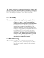
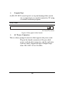
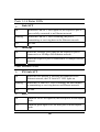
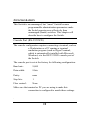
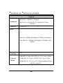
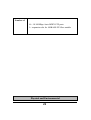
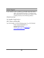
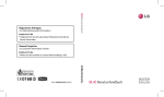
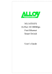
1
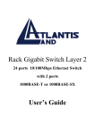
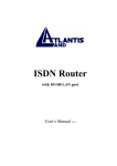
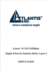
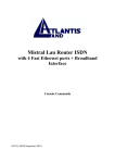
16 ports
10/100Mbps Fats Ethernet Switch
Layer 2
with 1 optional port
100Base-FX Fiber Module
USER’S GUIDE
The Atlantis Land logo is a registered trademark of Atlants Land
SpA. All other names mentioned mat be trademarks or registered
trademarks of their respective owners. Subject to change without
notice. No liability for technical errors and/or omissions.
FCC Warning
This equipment has been tested and found to comply with the
regulations for a Class A digital device, pursuant
to Part 15 of the FCC Rules. These limits are
designed to provide reasonable protection against
harmful interference when the equipment is
operated in a commercial environment. This
equipment generates, uses, and can radiate radio
frequency energy and, if not installed and used in
accordance with this user’s guide, may cause
harmful interference to radio communications.
Operation of this equipment in a residential area
is likely to cause harmful interference, in which
case the user will be required to correct the
interference at his/her own expense.
CE Mark Warning
This is a Class A product. In a domestic environment, this
product may cause radio interference, in which
case the user may be required to take adequate
measures.
UL Warning
a) Elevated Operating Ambient Temperature- If installed in a
closed or multi-unit rack assembly, the operating
ambient temperature of the rack environment may
be greater than room ambient. Therefore,
consideration should be given to installing the
equipment in an environment compatible with the
manufacturer's maximum rated ambient
temperature (Tmra).
b) Reduced Air Flow- Installation of the equipment in a rack
should be such that the amount of air flow
required for safe operation of the equipment is not
compromised.
c) Mechanical Loading- Mounting of the equipment in the rack
should be such that a hazardous condition is not
achieved due to uneven mechanical loading.
d) Circuit Overloading- Consideration should be given to the
connection of the equipment to the supply circuit
and the effect that overloading of circuits might
have on over current protection and supply
wiring. Appropriate consideration of equipment
nameplate ratings should be used when
addressing this concern.
e) Reliable Earthing- Reliable earthing of rack-mounted
equipment should be maintained. Particular
attention should be given to supply connections
other than direct connections to the branch circuit
(e.g., use of power strips).
TABLE
OF
CONTENTS
ABOUT THIS GUIDE............................................................................ 1
PURPOSE .................................................................................................... 1
TERMS/USAGE ........................................................................................... 1
INTRODUCTION .................................................................................. 3
FAST ETHERNET TECHNOLOGY ................................................................ 3
SWITCHING TECHNOLOGY ........................................................................ 4
VLAN (VIRTUAL LOCAL AREA NETWORK)............................................. 5
FEATURES .................................................................................................. 6
UNPACKING AND INSTALLATION ................................................ 7
UNPACKING ............................................................................................... 7
INSTALLATION ........................................................................................... 8
RACK MOUNTING ...................................................................................... 9
CONNECTING NETWORK CABLE ............................................................. 10
AC POWER .............................................................................................. 10
IDENTIFYING EXTERNAL COMPONENTS ................................ 11
FRONT PANEL .......................................................................................... 11
REAR PANEL ............................................................................................ 12
UNDERSTANDING LED INDICATORS ......................................... 13
POWER AND SYSTEM LEDS .................................................................... 13
PORTS 1~16 STATUS LEDS ..................................................................... 14
FIBER MODULE LEDS ............................................................................. 14
CONFIGURATION.............................................................................. 15
CONSOLE PORT (RS-232 DCE)............................................................... 15
CONFIGURING THE SWITCH ..................................................................... 16
LOGIN ...................................................................................................... 17
MAIN MENU ............................................................................................ 18
CONFIGURING SETUP SETTING................................................................ 19
CONFIGURING SYSTEM SETTING............................................................. 23
CONFIGURING FILE SETTING................................................................... 24
STATISTICS .............................................................................................. 25
TECHNICAL SPECIFICATIONS ..................................................... 28
A02-F16-F/M2 (september 2002)
ABOUT THIS GUIDE
Congratulations on your purchase of the 16-Port 10/100Mbps
Fast Ethernet Smart Switch. This device
integrates 100Mbps Fast Ethernet and 10Mbps
Ethernet network capabilities in a highly flexible
package.
Purpose
This guide discusses how to install your 16-Port 10/100Mbps
Fast Ethernet Smart Switch.
Terms/Usage
In this guide, the term “Switch” (first letter upper case) refers to
your 16-Port 10/100Mbps Fast Ethernet Smart
Switch, and “switch” (first letter lower case)
refers to other Ethernet switches.
1
INTRODUCTION
This chapter describes the features of the 16-Port 10/100Mbps
Fast Ethernet Smart Switch and some background
information about Ethernet/Fast Ethernet and
Switching technology.
Fast Ethernet Technology
The growing importance of LANs and the increasing complexity
of desktop computing applications are fueling the
need for high performance networks. A number of
high-speed LAN technologies have been proposed
to provide greater bandwidth and improve
client/server response times. Among them,
100BASE-T (Fast Ethernet) provides a nondisruptive, smooth evolution from the current
10BASE-T technology. The non-disruptive and
smooth evolution nature, and the dominating
potential market base, virtually guarantee costeffective and high performance Fast Ethernet
solutions.
100Mbps Fast Ethernet is a standard specified by the IEEE 802.3
LAN committee. It is an extension of the 10Mbps
Ethernet standard with the ability to transmit and
receive data at 100Mbps, while maintaining the
CSMA/CD Ethernet protocol. Since the 100Mbps
Fast Ethernet is compatible with all other 10Mbps
Ethernet environments, it provides a
straightforward upgrade and takes advantage of
3
the existing investment in hardware, software, and
personnel training.
Switching Technology
Another approach to pushing beyond the limits of Ethernet
technology is the development of switching
technology. A switch bridges Ethernet packets at
the MAC address level of the Ethernet protocol
transmitting among connected Ethernet or Fast
Ethernet LAN segments.
Switching is a cost-effective way of increasing the total network
capacity available to users on a local area
network. A switch increases capacity and
decreases network loading by dividing a local
area network into different segments, which don’t
compete with each other for network transmission
capacity.
The switch acts as a high-speed selective bridge between the
individual segments. The switch, without
interfering with any other segments,
automatically forwards traffic that needs to go
from one segment to another. By doing this the
total network capacity is multiplied, while still
maintaining the same network cabling and adapter
cards.
Switching LAN technology is a marked improvement over the
previous generation of network bridges, which
were characterized by higher latencies. Routers
have also been used to segment local area
4
networks, but the cost of a router, the setup and
maintenance required make routers relatively
impractical. Today switches are an ideal solution
to most kinds of local area network congestion
problems.
VLAN (Virtual Local Area Network)
A VLAN is a group of end-stations that are not constrained by
their physical location and can communicate as if
a common broadcast domain, a LAN. The
primary utility of using VLAN is to reduce
latency and need for routers, using faster
switching instead. Other VLAN utility include:
Security
Security is increased with the reduction of opportunity in
eavesdropping on a broadcast network because
data will be switched to only those confidential
users within the VLAN.
Cost Reduction
VLANs can be used to create multiple broadcast domains, thus
eliminating the need of expensive routers.
Port-based (or port-group) VLAN is the common method of
implementing a VLAN, and is the one supplied in
the Switch. Each Switch port can belong from one
to sixteen VLAN.
5
Features
16×10/100Mbps Auto-negotiation Ethernet ports
All ports support auto MDI/MDIX, so there is no need
to use cross-over cables or an up-link port
Full/half duplex transfer mode for each port
Wire speed reception and transmission
Store-and-Forward switching scheme capability to
support rate adaptation and ensure data integrity
Broadcast storm protection
Up to 4K unicast addresses entities per device, selflearning, and table aging
256KBytes on-chip packet buffer for each eight ports
Supports IEEE 802.3x flow control for full-duplex
mode ports
Supports Back-pressure flow control for half-duplex
mode ports
Optional one port 100BASE-FX Fiber module in the
rear panel for length extension
Supports Port-base VLAN and IEEE 802.1p QoS
RS-232 DCE console port for setting up and manage
the Switch via connection to a console terminal or PC
using a terminal emulation program
6
Standard 19” Rack-mount size
UNPACKING
AND
INSTALLATION
This chapter provides unpacking and setup information for the
Switch.
Unpacking
Open the shipping cartons of the Switch and carefully unpacks its
contents. The carton should contain the following
items:
One 16-Port 10/100Mbps Fast Ethernet Smart Switch
One AC power cord, suitable for your area’s electrical
power connections
Four rubber feet to be used for shock cushioning
Screws and two mounting brackets
One console cable
This User’s Guide
If any item is found missing or damaged, please contact your
local reseller for replacement.
7
Installation
The site where you install the hub stack may greatly affect its
performance. When installing, consider the
following pointers:
Install the Switch in a fairly cool and dry place. See
Technical Specifications for the acceptable temperature
and humidity operating ranges.
Install the Switch in a site free from strong
electromagnetic field generators (such as motors),
vibration, dust, and direct exposure to sunlight.
Leave at least 10cm of space at the front and rear of the
hub for ventilation.
Install the Switch on a sturdy, level surface that can
support its weight, or in an EIA standard-size
equipment rack. For information on rack installation,
see the next section, Rack .
When installing the Switch on a level surface, attach
the rubber feet to the bottom of each device. The
rubber feet cushion the hub and protect the hub case
from scratching.
8
Rack Mounting
The switch can be mounted in an EIA standard-size, 19-inch
rack, which can be placed in a wiring closet with
other equipment. Attach the mounting brackets at
the switch’s front panel (one on each side), and
secure them with the provided screws.
16 -P ort
POWE
R
SYST
EM
Link/AC
T
10 /10
0M bp
s Eth
ern
et Sm
art
Sw itc
h
FX
F DX
Figure 1. Combine the Switch with the provided screws
Then, use screws provided with the equipment rack to mount
each switch in the rack.
9
16- Por
POWE
SYST
R
t 10/ 10
0M bp
s Eth
ern et
Sm art
Sw itch
Link/ACT F X
EM
FDX
Figure 2. Mount the Switch in the rack
Connecting Network Cable
The Switch supports 10Mbps Ethernet or 100Mbps Fast Ethernet
and it runs both in half and full duplex mode.
These ports are Auto-MDI type port. The Switch can auto
transform to MDI-II or MDI-X type, so you can
just make an easy connection that without
worrying if you are using a standard or crossover
cable.
AC Power
The Switch can be used with AC power supply 100~240V AC,
50~60 Hz. The power switch is located at the rear
of the unit adjacent to the AC power connector
and the system fan. The switch’s power supply
will adjust to the local power source
10
automatically and may be turned on without
having any or all LAN segment cables connected.
IDENTIFYING EXTERNAL COMPONENTS
This chapter describes the front panel, rear panel, and LED
indicators of the Switch.
Front Panel
The figure below shows the front panels of the Switch.
Figure 3. Front panel of 16-port 10/100Mbps Fast
Ethernet Switch
LED Indicator
Comprehensive LED indicators display the status of the switch
and the network (see the LED Indicators chapter
below).
10/100BASE-T Twisted-Pair Ports
These ports support network speeds of either 10Mbps or
100Mbps, and can operate in half- and full- duplex transfer
modes. These ports also supports automatic MDI/MDIX
crossover detection function gives true “plug and play”
capability, just need to plug-in the network cable to the hub
directly and don’t care if the end node is NIC (Network Interface
Card) or switch and hub.
11
Console Port
An RS-232 DCE console port is set up and managed the switch
via a connection to a console terminal or PC using
a terminal emulation program.
Rear Panel
AC Power Connector
Figure 4. Rear panel of the Switch
AC Power Connector
This is a three-pronged connector that supports the power cord.
Plug in the female connector of the provided
power cord into this connector, and the male into
a power outlet. Supported input voltages range
from 100~240V AC at 50~60Hz.
12
U N D E R S T A N D I N G LED I N D I C A T O R S
The front panel LEDs provides instant status feedback, and help
monitor and troubleshoot when needed.
16-Port 10/100Mbps Ethernet Smart Switch
FX
POWER
Link/ACT
SYSTEM
FDX
1
2
3
4
5
6
7
8
9
10
11
12
13
14
15
16
Figure 5. LED indicators of the Switch
Power and System LEDs
POWER
On
: When the Power LED lights on, the Switch is receiving
power.
Off
: When the Power turns off or the power cord has improper
connection.
SYSTEM
Blinking
: When the CPU is working, the System LED is blinking.
On/Off
: The CPU is not working.
13
Ports 1~16 Status LEDs
Link/ACT
On
: When the Link/ACT LED lights on, the respective port is
successfully connected to an Ethernet network.
Blinking
: When the Link/ACT LED is blinking, the port is
transmitting or receiving data on the Ethernet network.
Off
: No link.
100Mbps
On
: When the 100Mbps LED lights on, the respective port is
connected to a 100Mbps Fast Ethernet network.
Off
: When the respective port is connected to a 10Mbps Ethernet
network
Fiber Module LEDs
FX Link/ACT
On
: When the fiber module is installed and connected to an
Ethernet network, the FX Link/ACT LED lights on.
Blinking : When the FX Link/ACT LED is blinking, the fiber module
is transmitting or receiving data on an Ethernet network.
Off
: No link.
FDX
On
: When the FDX LED lights on, the fiber port is in full duplex
mode.
Off
: When the green light is off, the fiber port is in half duplex
mode.
14
CONFIGURATION
This Switch is an unmanaged, but “smart” Switch because
programmable administration parameters make
the Switch operate more effectively than
unmanaged (dumb) switches. This chapter will
describe how to configure the Switch.
Console Port (RS-232 DCE)
The console configuration requires connecting a terminal, such as
a Workstation or a PC running a terminal
emulation program (such as HyperTerminal,
which is automatically installed with Microsoft
Windows) a to the RS-232 DCE console port of
the Switch.
The console port is set at the factory for following configuration:
Baud rate:
9,600
Data width:
8 bits
Parity:
none
Stop bits:
1
Flow control:
None
Make sure the terminal or PC you are using to make this
connection is configured to match these settings.
.
15
Configuring the Switch
The 16-Port 10/100Mbps Fast Ethernet Smart Switch has a
menu-driven console interface for smart switch
configuration. The Switch can be configured
through the serial port. A network administrator
can manage, control and monitor the switch from
the console program. This section indicates how
to configure the Switch to enable its smart
functions including:
Setup
There are two items such as Port Configuration and VLAN,
shown in the Setup screen. Each function of these two items will
be illustrated in the following sections.
System
In the System screen, Factory Reset, Change Password, Confirm
Password, Refresh Time, and Login Timeout, can be viewed and
changed. System Uptime can’t be altered and governed by the
Switch.
File
The Switch can be uploaded or downloaded its configuration file
by using Upload Configuration or Download Configuration in the
File setting screen.
Statistics
In the Statistics menu screen, each port’s data transferring and
receiving status can be viewed, but can’t be changed.
16
Login
First execute the terminal emulation program on the remote
workstation, and turn on the Switch. When login
to the Switch, the following screen (Figure 10)
prompt:
Password:
Figure 10. Login
Input the password in the blank, and then press Enter to login
Main Menu. If you manage the Switch for the
first time, you should input the factory default
password “admin” to login to the Switch. For
changing the password, first highlight System>
Change Password to input your new password,
and then highlight Confirm Password to input
your new password again to ascertain it.
17
Main Menu
The main menu appears, as shown in Figure 11. Find the console
keys in the lower part of the screen. Move to
highlight a desired option by using Up Arrow,
Down Arrow and Tab keys, and then press Enter
key to confirm. There are four options: Setup,
System, File, and Statistics, shown in the Main
Menu screen.
Figure 11. Main Menu
18
Configuring Setup Setting
Find that there are two items, including Port Configuration and
VLAN in Setup menu, shown as Figure 12.
Figure 12. Setup Menu
Port Configuration
In Port Configuration menu (Figure 13), each port’s (port 17:
Fiber Port) Speed, Flow Control, and QoS can be
controlled. Link Status is automatically
determined by the Switch and can’t be shifted.
19
Figure 13. Port Configuration
(1) Speed
There are five modes— Auto, 100M Full, 100M Half, 10M Full,
and 10M Half—for speed selections. To change
the speed setting, highlight Port and enter the port
number to select the desired port, next highlight
Speed, click Enter, and use Space Bar to toggle
back and forth between the five different options.
(2) Flow Control
This setting determines whether or not the Switch will be
handling flow control. To change the flow control
setting, highlight Port and enter the port number
to select the desired port. Set FlowCtrl to ON for
avoiding data transfer overflow. Or it sets to OFF,
there is either no flow control or other
hardware/software management.
20
(3) QoS
If some ports need to have the priority to manage the data
transfer, QoS should be change. QoS has two
functions to alter, High and Low. The default
settings of all ports’ QoS are High. To change the
QoS setting, highlight Port and enter the port
number to select the desired port. The default
settings of QoS are High. Set QoS to determine
which ports will always transfer their data first.
(4) Link Status
This value is automatically determined by the Switch and can’t
be changed. If there is a valid connection to the
Switch through that assigned port, the Link Status
will show the connecting speed. The status will be
Down if there is no connection through that port.
VLAN (Virtual Local Area Network)
Group individual ports into a small “virtual” network of their
own to be independent of the other ports.
Changing the VLAN, locate the port that needed
to set, select the “V” for joining the VLAN group
and the “-” for not joining. The default setting of
VLAN is shown as Figure 14.
21
Figure 14. VLAN Configuration
For example, there are five computers (PC1~PC5) connected to
the Switch’s port 1~5. They had been divided into two VLAN
groups: VLAN1 (PC1~PC4) and VLAN2 (PC2~PC5). There is
no way to connect PC1 and PC5 shown as Figure 15. If PC1 has
to connect to PC5, it should joint PC1 and PC5 in the same
VLAN.
VLAN1
1
2
3
4
X
2
3
VLAN2
4
5
Figure 15. There is no connection between PC1 and PC5
Using VLAN, it can divide the Switch into many independent
small switches. For example, in Figure 16, the Switch has been
22
divided into two VLAN groups. Both VLAN groups are
independent and there’s no link between these VLAN groups.
The Switch can be regarded as two smaller switches.
16-Port 10/100Mbps Ethernet Smart Switch
FX
POWER
Link/ACT
S Y STE M
FDX
1
2
3
4
5
6
7
8
9
10
11
12
13
14
15
9
10
11
12
13
14
15
16
1
2
3
4
5
6
7
8
16
X
VLAN1
VLAN2
Figure 16. Dividing the Switch into two smaller switches
Configuring System Setting
The System Configuration Menu screen (shown in Figure 17)
indicates the following information:
Factory Reset: Press to turn back to factory setting once
the setting in blur.
Change Password: Change the input password.
Confirm Password: Confirm the new input password.
Refresh Time: Set the refresh time of the device for
Statistics.
Login Timeout: Set the console idle time-out to log out
the smart menu when forgot to log out.
System Uptime: Indicate the time on powered up the
Switch.
23
Figure 17. System Setting
Configuring File Setting
The Switch can be uploaded or downloaded its configuration files
by using the File screen shown in Figure 18.
Upload Configuration: Select this for back up a file the
setting from the device. (in Hyper Terminal, Transfer >
Receive File)
Download Configuration: Select this for downlading the
back up file to the device. (in Hyper Terminal, Transfer >
Send File)
24
Figure 18. File installation
Statistics
Statistics Menu
In the Statistics menu screen (shown Figure 19), all ports’
transferring (Tx) and receiving (Rx) status
summaries can be viewed.
25
Figure 19. Statistics
Statistics Detail
Highlight Port and enter port number to view the statistics details
(see Figure 20).
26
Figure 20. Statistics Detail
27
TECHNICAL SPECIFICATIONS
General
IEEE 802.3 10BASE-T Ethernet
Standards
IEEE 802.3u 100 BASE-TX, 100BASE-FX Fast
Ethernet
Protocol
CSMA/CD
Data
Ethernet: 10Mbps (half duplex), 20Mbps (full duplex)
Fast Ethernet: 100Mbps (half duplex), 200Mbps (full
duplex)
Topology
Star
10BASE-T: 2-pair UTP/STP Cat. 3, 4, 5; up to 100m
Network
Media
100BASE-TX: 2-pair UTP/STP Cat. 5; up to 100m
100BASE-FX: 50/125 or 62.5/125µm multimode fiber
with SC connector
28
Number of
16 × 10/100Mbps Auto-MDIX STP ports
1 × expansion slot for 100BASE-FX fiber module
Physical and Environmental
29
AC inputs:
100~240V AC, 50/60 Hz internal
universal power
supply
Power Consumption:
12 watts. (max.)
Temperature:
Operating: 0°~40°C,
Storage: -10°~70°C
Operating: 10%~90% RH,
Humidity:
Storage: 5%~90% RH
Dimensions:
440 x 140 x 44 mm (W x H x D)
Weight:
2.0kg
Emissions:
FCC Class A, CE Mark Class A,
VCCI Class A
Safety:
cUL(1950), CB(IEC60950)
Performance
Transmits Method:
Store-and-forward
RAM Buffer:
512K bytes per device
Filtering Address Table:
4K entries per device
Packet
Filtering/Forwarding Rate:
10Mbps Ethernet: 14,880/pps
MAC Address Learning:
Automatic update
100Mbps Fast Ethernet: 148,800/pps
30
Product Support
If you continue to have problems you should contact the dealer
where you bought this product. If you have any
other questions you can contact the Atlantis Land
company directly at the following address:
AtlantisLand spa
Via Gandhi 5 Ing2,Scala A
20017 Mazzo di Rho(MI)
Tel: 02/93906085, 02/93907634(help desk) Fax: 02/93906161
Email: [email protected] or
[email protected]
WWW: http://www.atlantisland.it or
www.atlantis-land.com
31