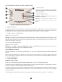
1
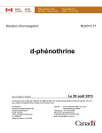
CARBON MONOXIDE MONITORING AND SHUTDOWN SYSTEM MODEL 12V Installation And User Manual (Rev. 102804NP) QUICK INSTALLATION TIPS AND TROUBLESHOOTING GUIDES ARE LOCATED ON THE BACK OF THE MANUAL Dear New UltraGuard Owner: Congratulations, you have taken an important step to help insure the health and safety of you and your family. We are proud to offer you our unique UltraGuard CO Monitor and Shut-Down System that detects CO, sounds an alarm and then proactively shuts down the furnace, the source of 95% of CO accidents in the home. In addition, UltraGuard will alert your Alarm Company if connected to their alarm panel. Please read this owner's manual carefully so you will have a better understanding of the effects of CO poisoning and how the UltraGuard System will help provide you with a safer, healthier indoor air quality. To your good health and safety, Geoff Winters, President Electronic Control Systems Table of Contents INTRODUCTION.................................................................................................................................................... 1 PACKAGE CONTENTS .................................................................................................................................... 1 MONITOR FEATURES ................................................................................................................................. 1 UltraGuard Front Panel Indicators.............................................................................................................. 3 CO DETECTOR FEATURES ............................................................................................................................. 4 PRODUCT DATA .................................................................................................................................................... 5 UltraGuard 12v Carbon Monoxide Monitor .......................................................................................................... 5 CO Detector .................................................................................................................................................... 5 INSTALLATION ..................................................................................................................................................... 6 Preliminary Things You Need to Know ................................................................................................................ 6 Understanding The UltraGuard Zones ............................................................................................................ 7 Zoned Mode ............................................................................................................................................ 8 Basic Mode ........................................................................................................................................... 9 Monitor Placement........................................................................................................................................... 10 Detectors Placement...................................................................................................................................... 10 CO Detectors Installation Instructions .......................................................................................................... 11 CO Detector Connections........................................................................................................................ 12 Single Detector Per Zone.......................................................................................................... 12 Multiple Detectors Per Zone 6-wire Connections ....................................................................13 CO Detector Replacement Procedure ................................................................................................. 14 Monitor Installation.......................................................................................................................................... 15 General Installation Notes ....................................................................................................................... 15 Electrical Connections ........................................................................................................................ 16 UltraGuard Remote Piezo Operation .................................................................................................. 16 Furnace Wiring.................................................................................................................................... 17 Low Voltage Furnace Control ............................................................................................................. 17 Power Connection ............................................................................................................................... 18 Final Installation .............................................................................................................................................. 18 Configuration ................................................................................................................................................ 18 Test The System ............................................................................................................................................ 19 Burglar Alarm Panel Connection .................................................................................................................. 19 Fire Alarm Panel Connection........................................................................................................................ 20 MAINTANANCE................................................................................................................................................... 21 WHAT TO DO IF THE ALARM SOUNDS ....................................................................................................... 21 What You Should Know About Carbon Monoxide............................................................................................... 22 Develop Your Own Safety Plan .................................................................................................................... 22 Conditions Which Can Result In Temporary Elevated CO Level Situations................................................22 LIMITED WARRANTY ......................................................................................................................................... 23 TROUBLESHOOTING ...................................................................................................................................... 24 QUICK INSTALLATION TIPS .................................................................................................... BACK COVER I n ICna n da ad a t htihsi seeqquui ippm maayy nn ese ud s ei n d in Ca an meen ntt m oo t tb eb u c o m m e r c ioam l /m in uisatlr/i ianl di u n ss tt railal a ed rc l ti inosnt s a!l l a t i o n s ! INTRODUCTION UltraGuard 12V is an interactive alarm system primarily intended for use with multiple Carbon Monoxide (CO) Detectors to detect CO and turn off the primary sources of this dangerous gas the furnace and hot water heater. This unit is suitable for residences, motels, hotels and commercial or industrial system applications. The UltraGuard 12V, when properly installed will shut down a furnace when CO is detected. The shutdown can be accomplished by interrupting either the high voltage or low voltage furnace electrical circuit. UltraGuard 12V allows automatic restart of the furnace when CO dissipates. Additionally, the internal temperature sensor will signal the alarm panel in a low temperature condition. As an option, up to three remote piezo alarms can be used with the UltraGuard 12V Monitor. PACKAGE CONTENTS · One UltraGuard 12V Carbon Monoxide Monitor · May be shipped with one or more UltraGuard 12VDC Carbon Monoxide Detectors · Installation Hardware · User Manual MONITOR FEATURES The UltraGuard 12V Monitor has the following features: · Internal audible alarm (sounder). · Detector inputs for up to four CO zones. Each zone can monitor up to 5 CO Detectors. · Four zoned outputs for interface to an alarm panel (each output corresponds to one of the four Detector zone inputs). Each of these outputs has an independent set of contacts that provide separate alarm signals from each zone. · Self-contained furnace control relay. Upon receiving an alarm from any of the CO Detectors, the UltraGuard 12Vs furnace control relay will shut down the furnace or/and hot water heater to which it is attached. · Additional features include a set of relay contacts that open when ANY CO Detector alarms and a separate set of contacts that open when ANY CO Detector has a fault condition. This allows the system to be used as a simple stand-alone alarm panel. · The UltraGuard 12V Monitor is self-configuring. Once the system is installed, an internal configure jumper will cause the UltraGuard 12V to determine and store the installation (used and unused zones) configuration. This eliminates the need for jumpers and resistors on the UltraGuard 12V Monitor circuit board. · A re-settable internal five-year clock provides a warning when the attached CO Detectors are in need of replacement. · An internal temperature sensor will cause the UltraGuard 12V Monitor to chirp if the temperature drops below 45F, while providing an alarm panel output. When a fault is detected, the microprocessor determines the type of fault, initializes an audible alarm and displays a blink sequence on the Zone indicator light that identifies the type of fault. This feature can save substantial troubleshooting time and unnecessary service calls. 1 Seven indicator lights on the front panel keep the user aware of the status of each function. Five types of faults are indicated by a repeating pattern of a blinking light on the affected zone: 1 - CO Detector generated fault/warning - pause - 2 - Broken or disconnected CO Detector power -- pause -- 3 - CO Detector line broken or disconnected --- pause --- 4 - Shorted CO Detector line ---- pause ---- 5 - Shorted CO Detector power - - - - - pause ----- All features are only available when the UltraGuard 12V is connected to a UL listed fire and/or burglar alarm panel with auxiliary signaling zones which can be designated for CO Detector use only. When the UltraGuard 12V is used in a residential application, the alarm panel shall be UL listed for household use (UL Standard 1023, Household Burglar Alarm or UL985, Household Fire Alarm) and when it is used in a commercial application, the alarm panel shall be UL listed for Commercial Fire Alarm use (UL864) or any of the following UL commercial burglar alarm categories: UL365, UL609 or UL1610. WARNING: The UltraGuard 12V Monitor is not a CO Detector. See chapters related to CO Detectors in this manual. 2 ULTRAGUARD FRONT PANEL INDICATORS j Reset Button Used to reset the system under various conditions. Please refer to appropriate sections of this manual for detailed descriptions. k Power Light (Green) Steady On Indicates normal (non-alarm) operation and requires no response. Blinking low temperature condition (below 45°F) has been detected. See Item l for details. Figure 1. UltraGuard Front Panel Features l Temperature Sensor If temperature drops below 45°F the Monitors alarm chirps (Item s) and Power Light blinks (Item k). The UltraGuard signals the alarm panel (if connected), which will notify the monitoring station of the condition. When the temperature rises above 45°F the UltraGuard will return to normal operation and the Power Light will return to the steady on condition. m Replace Detector Light (Yellow) Light Off Normal Condition Blinking (alarm chirps Item s) Indicates that the UltraGuard internal clock has determined that the CO Detector(s) need to be replaced in order to provide continuing protection. The Alarm may be silenced by pushing the Reset button (Item j). The light will remain ON until the CO Detectors are replaced and the system is reset. Promptly replace the CO Detectors! (See Replacement Instructions on the Page ). nopq Zone Alarm Lights (Red) Light Off Normal Condition Blinking (alarm Item s is ON and Trouble Light item r is OFF) Indicates that the CO Detector(s) in that zone is (are) detecting DANGEROUS LEVELS OF CARBON MONOXIDE. LEAVE THE AREA AT ONCE! When CO dissipates the zone light will go from blinking to a steady on condition indicating that an alarm condition has occurred. Note: An alarm condition that occurs and then clears itself will cause the zone light to stay on (steady). Furnace operation will only be interrupted while the alarm condition exists. Determine the cause of the alarm! Press and hold the RESET button (Item j) until the zone light turns off. r Trouble Light (Yellow) Light Off Normal Condition Steady On (Zone light flashing and the UltraGuard Monitor alarm item s is chirping) indicates that: CO Detector is faulty and should be repaired or replaced OR any one of the 5 faults shown on page 2 exists and must be corrected. NOTE: the alarm may be silenced by pushing the Reset button (item j). If the trouble condition clears itself, the alarm will stop chirping but the trouble light will stay on and the Zone light will continue to flash, indicating the Zone that caused the Trouble light to be on. For your continued protection, the cause of the Trouble light should be determined. s Audio Alarm. A chirping sound is triggered when dangerous or fault conditions occur (see items j r for details). 3 CAUTION: The UltraGuard 12V System relies on the integrity of the attached CO Detector(s) to provide both the alarm panel signal and to turn the furnace off. Correct installation of each CO Detector and its prompt replacement when required, are essential to proper operation of the UltraGuard 12V. CAUTION: Proper placement of the CO Detector in accordance with the manufacturers recommendations is essential to the function of the CO Detector and therefore to the function of the UltraGuard 12V. CAUTION: The UltraGuard 12V system may be installed with or without a battery backup. If the system is installed WITHOUT battery backup and power to the UltraGuard 12V fails or is turned off, the furnace will be shut down, a fault / trouble signal will be sent to the Alarm Panel and, the Power Light will turn off AND the internal alarm horn WILL NOT operate. On restoration of power the UltraGuard 12V will remember the system configuration and ANY alarm condition that existed when the power loss occurred. CO DETECTOR FEATURES The UltraGuard 12V System may be shipped with one or more CO Detectors UltraGuard 12V CO 12VDC that conform to UL 2034 for CO sensitivity. Although all the information from CO Detectors is collected, processed and acted upon by the UltraGuard Monitor, each UltraGuard 12VDC detector has an array of features of its own. Each detector has an audible alarm j and RED LED indicator k (figure 2). Under normal circumstance with the detectors operating properly the RED LED k flashes once every 30 seconds, indicating that the alarm is powered and active. IN ALARM CONDITION (WHEN CO IS DETECTED) the RED LED turns "on" for 2 seconds and "off" for 4 seconds with 4 short beeps for 1 second and 5 seconds of silence. The RED LED will illuminate and the alarm relay will be energized (NO or NC). Pushing and holding the test/reset button for 3 seconds will silence the alarm for about 4 minutes. After 4 minutes, the alarm will sound again until the unsafe CO concentration is reduced. The alarm will automatically sense when the level of CO in the air falls below the danger level. IN TROUBLE CONDITION The detector self-tests every 10 minutes. The detector will beep and the Indicator/Test button will flash twice every 30 seconds if a fault/trouble is detected. This is an indication of a malfunction and that the detector requires immediate servicing. Figure 2. CO Detector Front Panel Features 4 PRODUCT DATA ULTRAGUARD 12V CARBON MONOXIDE MONITOR Power: Canadian installations must be in compliance with the Canadian Electrical Code for a conduit opening for permanently mounted equipment. The UltraGuard 12V must be connected to the 12 volt Aux. Output of the UL listed alarm panel or powered as shown below: The UltraGuard 12V may be used in stand alone environment only if powered by any power limited Household Fire Alarm, UL Listed Power Supply that meets the power requirements. When used in a residential installation, the power supply must meet UL standard UL985. When used in a commercial installation the supply must meet UL standard UL864. Alternate Power Source (provided as a separate cost item): Power may also be supplied by any UL1481 12V DC power limited supply (such as the Altronix Model AL300ULX). Check local authority for the required stand-by time. Use the battery calculation tables provided with the power supply to determine the correct battery rating. If the UltraGuard 12V is installed as a stand-alone system ECS recommends using alternative power supply with rechargeable batteries for extra protection! Current Draw: 0.074 Amps independent of the number of CO Detectors attached (Use this number to calculate standby time). To calculate alarm time (after standby) the UltraGuard 12V Monitor draws 0.10Amps and each CO Detector draws 0.060 Amps when in alarm (0.10+0.06*20=1.3Amps maximum with 20 CO Detectors in alarm). When used with remote piezo, battery life must be calculated with the additional piezo current added. Field Wiring: CAUTION: Wiring (not EOL resistors) must not exceed 100 ohms as measured from the UltraGuard Monitor terminals. Alarm panel ............................................22 ... 14AWG Operating Temperature: .......32°F to 120°F (0°C to 50°C) Furnace ..................................................14 12AWG Operating Humidity:...............15 95% RH Relay Contacts: Horn (sounder):....................Loud internal alarm over 75 db Alarm Panel outputs: ...................1A 28VDC Low Temperature Detection Threshold: 45°F. Temperature below Furnace Relay: ............................16A 250VAC max 45°F causes a fault indication at an attached alarm panel Remote Piezo (optional):........................300 mA @ 12 Volt Self-Diagnostics: On power up the UltraGuard 12V performs a Self-Test. During the self-test, each of the LED lights momentarily and the UltraGuard sounder chirps. The microprocessor turns on the Power Light, which indicates that the system has power and is functioning. At any time the UltraGuard 12V is not in an alarm condition, holding the RESET button down (item j figure 1, page 3) will cause the unit to chirp and the indicator lights to flash sequentially indicating normal operation. CO DETECTOR Power.........................................12VDC nominal Current Draw Standby .......................0.06 mA. Alarm ..........................60 mA. Trouble........................30 mA. Field Wiring...............................14-22 AWG Relay Contacts...........................Dry form 'C' (0.1A, 12VDC) non-latching Operating Temperature..............4.4° C 37.8° C (40° F - 100° F) Operating Humidity...................15-95% RH Horn (Sounder) Loudness .........85 db @ 10 ft (3.3 meters) 5 Sensitivity Setting: CO Levels Response 30 ppm....................None 70 ppm....................60-240 min 150 ppm..................10-50 min 400 ppm..................4-15 min INSTALLATION To avoid common errors, unnecessary troubleshooting and make the installation more efficient we suggest the following installation sequence: 1. 2. 3. 4. 5. 6. 7. 8. 9. 10. 11. 12. Understand UltraGuard ZONED and BASIC modes of operation vs. your installation requirements and capabilities. Plan detectors and monitor placement. Wire the facility/residence. Install UltraGuard CO detectors. Turn off the furnace power. Install UltraGuard Monitor. Connect UltraGuard Monitor to furnace circuit. Connect UltraGuard CO detectors wires to monitor. Place J7 on the UltraGuard Monitor board into CONFIG position. Power the UltraGuard system. Wait as the monitor goes through configuration sequence. Test the system (individual detectors and the monitor). Connect UltraGuard Monitor to alarm panel. PRELIMINARY THINGS YOU NEED TO KNOW Knowing the answer to the following will help you set up for installation: · · · · · What power source you will use to power the UltraGuard? You have two choices: 1. Auxiliary Alarm Panel power supply. 2. Stand Alone backup power supply such as Altronix Model AL300ULX. How many CO Detectors are required in this installation? You can install 5 detectors per UltraGuard zone (20 detectors total). If you are connecting the UltraGuard to an alarm panel how many zones are available in the panel? The number of zones in the alarm panel affects the manner and number of signals the UltraGuard can send to the alarm panel. To fully utilize UltraGuards potential the alarm panel has to have 6 free zones if ALL UltraGuards detector zones are wired. Please read Understanding UltraGuards Zones section carefully! Do you need to install additional external audio alarms/piezos? UltraGuard can handle three additional external piezo alarms. Note that the installation of piezos will use one zone on the UltraGuard board and thereby reduce the total number of CO Detectors you can install to 15. How will you connect the UltraGuard Monitor to a furnace? You can shutdown the furnace by connecting to either high voltage (emergency switch) or low voltage (at thermostat) circuits. 6 UNDERSTANDING THE ULTRAGUARD ZONES If you intend to connect the UltraGuard to an alarm panel please take time to read this section. Understanding how UltraGuard distributes signals will affect your installation plan. UltraGuard has four CO Detector zones and six alarm panel output zones (see figure 3). Figure 3. UltraGuard Zones Figure 3 shows the UltraGuard zones available to you for the installation. Names of the zones correspond with the names you find on the UltraGuard electronic board. The four CO Detector zones both power detectors in the zone and receive alarm and fault signals from detectors in this zone (note the number of wires used between detectors, detectors and the monitor, and between monitor and alarm panel). If you need detectors internal fault/trouble supervised you will need 6 wires to connect detectors in the system. Should you decide not to report internal detectors faults to the UltraGuard monitor, you will need only 4 wires between detectors. . Note that the line troubles and faults are still supervised. NOTE: Detectors wiring does not affect individual detector internal fault alarm. The UltraGuard Monitors six output zones are designed to communicate three types of signals to an alarm panel: 1. CO Alarm. 2. Temperature (If ambient temperature drops below 45ºF). 3. Fault. The UltraGuard Monitor can report signals to an alarm panel in two different modes. Placing J6 on the UltraGuards board to an appropriate position sets the mode. These modes are: 1. ZONED when ALL UltraGuard reporting capabilities are employed. 2. BASIC when minimum capabilities are used. NOTE: Monitor mode affects ONLY how signals are reported to an alarm panel. It DOES NOT affect how the UltraGuard Monitor reports information through its faceplates lights! 7 ZONED MODE Figure 4 shows how the UltraGuard Monitor distributes the signals in the ZONED mode. Figure 4. Zoned Mode Signals Distribution Z1 ALARM, Z2 ALARM, Z3 ALARM, and Z4 ALARM can output ONLY CO ALARM signals from the corresponding input zones ZONE 1, ZONE 2, ZONE 3 and ZONE 4. In the Zoned mode a CO alarm signal comes from a CO Detector into a corresponding INPUT Zone and, then, is channeled to a corresponding OUTPUT Zone, which can be output further to an alarm panel. The TEMPERATURE and FAULT signals are sent to the alarm panel the same way in both ZONED and BASIC mode. FAULT signals from all the CO Detector Zones are channeled into a single FAULT ANY zone for a further transmission to an alarm panel. The TEMPERATURE signal always communicates to ALARM ANY zone. In the ZONED mode ONLY TEMPERATURE signal can be retrieved from ALARM ANY zone! In order to utilize all the reporting features of the UltraGuard Monitor an alarm panel has to have as many zones available as are employed for CO Detectors PLUS 1 for Temperature and 1 For Fault. Example I. There are 20 detectors installed. All four Input Zones are involved. Scenario 1. There are 6 Zones available on the alarm panel. All the features CO Alarms from specific zones, temperature and faults will be reported to the alarm panel. Scenario 2. There are 5 Zones available on the alarm panel. You have to decide what are the priorities in reporting. You need to drop either temperature or fault reporting. Scenario 3. There are 4 Alarm Panel Zones available. You will, probably, need to drop both temperature and fault reporting if you decide to use ZONED configuration so that CO alarms are reported separately to each alarm panel zone. 8 Example II. There are 7 detectors installed. 5 on Zone 1 and 2 on Zone 2. Scenario 1. There are 4 Alarm Panel Zones available. All the features CO Alarms from specific zones, temperature and faults can be reported to the alarm panel. Scenario 2. There are 3 Zones available on the alarm panel. You have to decide what are the priorities in reporting. You need to drop either temperature or fault reporting. Scenario 3. There are 2 Alarm Panel Zones available. You will, probably, need to drop both temperature and fault reporting if you decide to use ZONED mode. BASIC MODE Figure 5 shows how the UltraGuard Monitor distributes the signals in the BASIC mode. ULTRAGUARD MONITOR CO DETECTORS LEGEND: Alarm Signal ALARM PANEL INPUT OUTPUT ZONE 1 Z1 ALARM ZONE 2 Z2 ALARM ZONE 3 Z3 ALARM ZONE 4 Z4 ALARM TEMPERATURE ALARM ANY Z1 FAULT ANY Z2 Fault Signal Temperature Figure 5. Basic Mode Signals Distribution This mode is useful when only one or two zones are available in an alarm panel. As mentioned in the ZONED mode description, TEMPERATURE and FAULT signal reporting does not change with the type of mode. The only difference is that ALARM signals from all four DETECTOR INPUT zones are channeled into a single output zone ALARM ANY. Since LOW TEMPERATURE signal is delivered through the same ALARM ANY zone as the CO ALARM, there is no way to distinguish between ALARM and LOW TEMP on the alarm panel level in the BASIC mode. In addition, specific zoning for the ALARM signal is lost. Z1 Z4 ALARM output zones are not functioning. Again, the UltraGuard Monitors ability to report three conditions on its faceplate IS NOT affected! 9 MONITOR PLACEMENT The UltraGuard Monitor may be placed on any wall that provides convenient access to the furnace emergency shut off switch wiring. For ease of use the UltraGuard Monitor should be placed at or near eye level. Locations to Avoid: As with any electronic device, the following locations should be avoided: · Within 5 feet of any cooking appliance. · Near open windows or doors. · Near a bathroom where the moist air from the shower could result in the UltraGuard becoming repeatedly wet. · Very cold or very hot environments where the ambient temperature can exceed the recommended operating range of the unit 32°F to 120°F (0°C to 50°C). The UltraGuard Monitor should not be located on an outside wall where severe cold weather could cause a false low temperature alarm. NOTE: The use of a battery backup power supply, as indicated in the "Alternate Power Source" section, will help to prevent momentary furnace interruptions and alarm trouble indications. WARNING: Always turn the furnace circuit breaker off before installing or servicing an UltraGuard system. Before proceeding, verify that the power has been disconnected from the furnace and the furnace emergency shut off switch. Zone Relay Outputs should only be connected to power limited circuits. Please note that CO Detector circuits are power limited, and furnace wiring is not power limited. DETECTORS PLACEMENT One of the most important considerations in any CO alarm system is the location of the Detectors. Statistics of the National Fire Protection Association (NFPA) show that most of the fatal CO occurrences happen at night while people are sleeping. Early warning of CO is best achieved by the correct installation of CO Detectors. Placement of a Detector in a garage may cause an alarm due to CO from automotive exhaust. RECOMMENDED MOUNTING LOCATIONS Put a CO Detector inside each bedroom where the occupant closes the door while sleeping. A closed door can block particulate smoke, but CO gas is likely to get through. Please conform to local building codes and regulations. Figure 6. Recommended CO Detectors And Monitor Placement For Multi-Level Residence Figure 7. Recommended CO Detector Placement For Single Floor Residence NOTE: Carbon Monoxide is lighter than air and, therefore, rises. CO Detector must be mounted on the wall or ceiling more than 5 feet above the floor. WALL LOCATION: Locate the top of the CO Detector 5 feet and above from the floor (figure 8). CEILING LOCATION: CO Detector should be mounted as close as possible to the center of a hallway or room. If this is not possible, the edge of the CO Detector should be at least 4 inches from any wall. Figure 8. CO Detector Wall Placement Good ventilation is recommended when household cleaning supplies or similar contaminants are stored or frequently used. 10 CO DETECTOR INSTALLATION INSTRUCTIONS Select proper location (SEE PAGE 10) A mounting plate is provided on the back of the CO Detector. Remove the mounting plate from the back of the CO Detector by holding the mounting plate and twisting the CO Detector in the direction indicated by the "OFF" arrow on the Detector cover. To insure aesthetic alignment of the CO Detector with the hallway or wall, the UP ARROW on the mounting plate must be: · Parallel with the hallway walls when ceiling mounting · Pointed upward when wall mounting Attach the mounting plate on the wall. Be sure the UP text and arrow are facing up. Use the screws and anchors provided to secure the mounting plate. WIRING INSTALLATION Internal terminal block for 14-22 AWG wires. 8 screw terminals at 0.2" (5 mm) spacing. Drill hole in wall or ceiling at center of plate, and pull system wires through the hole. Remove CO Detector cover by using the special tool provided on the three locking tabs on the CO Detector base (see figure 9). Pull wires through hole at center of CO Detector base and connect to the internal terminal block as shown on the following wiring diagrams (see figure 10). NOTE: NO contacts may be wired to UltraGuard system panel. Alignment marks are provided on the edge of the trim plate and the CO Detector. After installing the mounting plate, place the CO Detector on the mounting plate with the alignment marks lined up. Twist the Detector in the direction indicated by the "ON" arrow on the Detector cover until it locks in place. CO DETECTOR CONNECTIONS There are three distinct variations of CO detector connections in the UltraGuard system: 1. Each UltraGuard monitor zone is connected to a single detector (requires 4-wire connections). 2. Multiple detectors are connected to one UltraGuard zone (requires 6-wire connections). CAUTION: Non-supervised wiring methods have not been investigated by UL and are NOT recommended! Each connection variation requires different configurations of the detectors installed. This is achieved by placing of End-OfLine Resistors (EOLR) and jumpers on the detectors as described below. 11 SINGLE DETECTOR ON A ZONE CONNECTION If a zone has only one detector all the EOLRs and a jumper must be installed on this detectors board (see figures 11 and 11a): · 2.7K (Red-Gray-Red) EOLR must be installed between contacts 1 & 2 · 5.6K (Green-Blue-Red) EOLR must be installed between contacts 4 & 5 · 10K (Brown-Black-Orange) EOLR must be installed between contacts 7 & 8 · Jumper must connect contacts 4 & 7. Detector is connected to the UltraGuard Monitor with 4 wires (Figure 11a). 8 J2 RLY1 RLY2 C6 AZ846-5 700339 0038 A AZ846-5 700339 0038 A + 4 5 R17 R16 2 3 + NC 6 7 12SIR 5 CJ5 TB1 _ 12VDC 4 (-)12V 6 QGI 8 TVS1 1 7 10K TROUBLE 2 S(+) 4 C NO NC C NO ALARM TROUBLE JUMPER 3 2.7K Resistor (Red-Gray-Red) 3 S(-) 5.6K ALARM 10K Resistor (Brown-Black-Orange) 2 5.6K Resistor Jumper (Green-Blue-Red) (Wire) 2.7K POWER 1 (+)12V (Power Limited) 1 Figure 11. Single detector on a zone configuration Figure 11a. Single detector on a zone connection 12 MULTIPLE DETECTORS PER ZONE. With multiple detectors per zone 4-wire connections between the first detector on a zone and the UltraGuard Monitor and 6wire connections between each subsequent detector on the same zone are utilized. This variation requires that the first and the last detectors on a zone are configured differently: FIRST DETECTOR on a zone (Figure 12): · Jumper must connect contacts 4 & 7. LAST DETECTOR on a zone (Figure 12a): · 2.7K (Red-Gray-Red) EOLR must be installed between contacts 1 & 2 · 5.6K (Green-Blue-Red) EOLR must be installed between contacts 4 & 5 · 10K (Brown-Black-Orange) EOLR must be installed between contacts 7 & 8. 1 _ 2 3 + NC 12VDC 4 5 6 7 8 1 _ C NO NC C NO ALARM TROUBLE 2 3 + NC 12VDC Jumper (Wire) 4 5 6 7 8 C NO NC C NO ALARM TROUBLE 2.7K Resistor 5.6K Resistor 10K Resistor (Red-Gray-Red) (Green-Blue-Red) (Brown-Black-Orange) Figure 12. First detector on a zone configuration LAST DETECTOR 8 10K TROUBLE 7 6 5 5.6K ALARM 4 3 2 1 2.7K POWER Figure 12a. Last detector on a zone configuration SECOND FIRST DETECTOR DETECTOR 8 8 7 7 6 NC 6 5 5 4 4 3 NC 3 2 2 1 1 4 (-)12V 3 S(-) 2 S(+) JUMPER 1 (+)12V (Power Limited) Figure 12b. Multiple detectors per zone 6-wire connection NOTE: Each of the CO Detector inputs is considered a separate zone that corresponds to a specific zone alarm output i.e. ZONE 1 CO Detector input is associated with the Z 1 output to the Alarm Panel. The End Of Line Resistors (EOLR) must be installed as outlined in Figure 13. Note that the wire lead at one end of the resistor must be bent over against the body of the resistor so that both leads are at the same end of the package. Cut both leads to the length shown and insert the leads into the terminal strip as shown. After tightening the terminal strip screws, tug on the resistor with a pair of needle nose pliers to verify a good mechanical connection. Install the Mocap plastic sleeve provided, completely covering the resistor and leads, to protect the leads from contacting other conductive components. Figure 13. EOLR installation 13 To make your CO Detector tamper resistant, a locking pin has been provided in the bag with the screws and anchors. Using this pin will deter children and others from removing the Detector from the mounting plate. To use the pin insert it into the hole in the side of the Detector after the Detector has been installed on the mounting plate (figure 14). To remove the Detector, use long nose pliers pull the pin out of the hole; it is now possible to remove the Detector from the mounting plate. Figure 14. The Detector box contains two self-adhesive labels. You should write the telephone numbers of the emergency service provider and a qualified technician in the space provided on the labels. Place one label next to the Detector, and the other label near a source of fresh air where you plan to gather after the Detector indicates the presence of carbon monoxide. CO DETECTOR REPLACEMENT PROCEDURE CAUTION: When a CO Detector is removed from the UltraGuard system for replacement, it will cause a trouble condition (-- pause -- on the monitor zone lights). You must notify your central monitoring company before replacing the CO Detectors. The alarm may be silenced by pressing the RESET button (item j, figure 1, page 3). Replacing the CO Detector will return the UltraGuard to normal operation. The first (closest to the Monitor) and last (farthest from the Monitor) Detectors for each zone have unique internal configurations (see figures 11, 11a, 12, 12a, pages 12-13 ). Please make sure that the internal configuration is replicated: If the old Detector has resistors and jumper install them into the new Detector If the old detector does not have resistors and jumpers leave contacts empty. IF THE ORIGINAL SETUP IS NOT REPLICATED THE DETECTORS WILL NOT WORK! CAUTION: When the installation is complete it must be verified with the CO Detector test button. When the CO Detector test button is pressed the UltraGuard yellow trouble light must light at the same time as the red zone light. if the yellow light is delayed by two or three seconds these resistors are not installed correctly and the system will not shut the furnace down correctly. After replacing the CO Detectors it is necessary to reset the internal 5-year clock on UltraGuard Monitor and the indicator lights (items m, nopqand r, figure 1, page 3). Press and hold the RESET button until the Replace Detectors light goes out and the UltraGuard Monitor alarm chirps (2 to 5 seconds). 14 MONITOR INSTALLATION The UltraGuard Monitor is designed to be mounted in a wall with the three-gang electrical box provided. The UltraGuard 12V must never be mounted without the use of a UL approved wall box. Some municipalities require furnace wiring to use BX cable. In these areas replace the Blue Plastic Wall Box (provided) with a 3 gang steel box. NOTE: If you are a homeowner and, after reading these instructions, you believe that mounting the box and/or the wall wiring is unclear to you, it is recommended that you hire a licensed contractor to do the installation. The installation of this equipment must be in accordance with the National Electrical Code (NEC) and local building regulations. Remove the front panel retaining screws and remove the UltraGuard Monitor from its blue wall box. Set the Monitor aside in a safe location. The wall box should be mounted using good construction practices. For ease of use the box should be located between 52 inches and 66 inches above the floor (approximately eye level). CAUTION: Some of the following steps require wiring connections within the wall box. Failure to observe the directions, good wiring practices or the NEC standards can result in improper operation; damage to the UltraGuard 12V or in the worst case no furnace shutdown protection. CAUTION: The furnace control section and the Alarm / Alarm Interface section are separated by a barrier. The 120VAC furnace wiring MUST be kept on the same side of the barrier as the pre-wired pigtails. Failure to observe this caution could damage the alarm system or lead to erratic operation. All of the low voltage wiring MUST be kept on the Alarm / Alarm Interface side of the barrier. Never remove the barrier, to do so will violate UL safety requirements. GENERAL INSTALLATION NOTES Wall Box Mounting Instructions Choose an area of wall accessible to the furnace cutoff switch wiring and not over a wall stud. Using the enclosed template cut a hole in the wall approximately 6wide x 3.8high to mount the wall box. Be sure that the hole is (level) square with the floor. Wire Entry Location These directions apply to the plastic three-gang outlet box provided in the kit. The box provided is designed for use with sheet rock though similar (UL listed) boxes are available for stud mount and may be used. For ease of wiring it is recommended that a deep, rather than a shallow, box is selected. CAUTION: Some locations require the use of BX to the furnace and, therefore must be installed using a steel wall box. The wiring outline below is intended as a guide only. Some box or wall wiring may require a slightly different wiring. NEVER allow the furnace wiring to push against the barrier or to be on the low voltage side of the barrier. ALWAYS observe the NEC and local regulations. Exercise care to avoid pinching wires when screwing the front panel in place. When installing the wall box it may be convenient to arrange the wiring in the wall beforehand. To insure ease of installation and avoid interference with the required separation of the 120VAC and the low voltage; wires should enter the wall box as follows (see figure 15): · Furnace Power Far right from below · Low voltage DC Far left from above · CO Detectors Center from above · Alarm Panel Center from below In practice, if there is room behind the wall box, the CO Detector, Furnace Cable and Alarm Panel wiring can be brought in from the back of the box. Figure 15. Wire arrangement inside the box 15 All low voltage wiring should be stripped back ¼ from the end for insertion into the removable plug. NEVER allow bare wire to extend above the connector plastic shell. Wires shorted together may result in improper operation or permanent damage to the UltraGuard 12V. WIRING CAUTION: · Open (unscrew) the terminal strip clamp before inserting wire · Never bend wire back on the insulation · DO NOT allow insulation to be trapped in the connector clamp · After tightening the terminal strip clamp, tug on the wire to verify a good connection CAUTION: Always observe the separation of the furnace 120VAC wiring and the low voltage wiring. The 120VAC wiring MUST be kept to the right of the barrier and the low voltage wiring to the left of the barrier. NEVER remove the barrier or operate the system with a damaged or removed barrier. ELECTRICAL CONNECTIONS The UltraGuard 12V has been designed to simplify the installation process. All low voltage connections are made using removable plugs (a typical application is shown in Figure 16). This avoids having to balance the panel while attaching wire. Only the 120VAC furnace control wiring is permanently attached to the UltraGuard Monitor printed circuit board. CAUTION: All wiring to the removable connectors is accomplished by stripping ¼ of insulation from the wire to be connected. Never allow bare wire to extend above the connector shell. Figure 16. Before beginning to wire the Monitor place the Zoned/Basic jumper J6 (Figure 17) in the correct position for this installation (see Understanding The UltraGuard Zones section, page 7). If the Zoned/Basic jumper is to be moved; first move the jumper J6 to the desired function, then once the unit is powered up, push and hold the reset button until the UltraGuard Monitor goes through its self test routine (lights flash in sequence and beeper sounds). The J6 setting is now stored in permanent memory. NOTE: Unused zones do not require jumpers or resistors. Figure 17. UltraGuard Electronic Board REMOTE PIEZO ALARM OPERATION Selecting the external alarm with jumper J8 (in the Ext. Alarm position - figure 17 above) allows up to three piezo alarms to be attached to the Zone 4 input (J3). The (-) side of the piezo must be attached to the end terminal (return) and the (+) terminal must be connected to pin 13 (+12). Zone 4 is a monitored input and must be terminated with two resistors as shown in Figure 18. The unique piezo resistor (150 ohm 1W, Brown-Green-Brown) EOL resistor must be placed across the terminals of the last piezo (as shown in Figure 18). The two middle terminals of the Zone 4 connector must have a 15K (Brown-Green-Orange) resistor. Figure 18. External alarm installation (not fully supervised) CAUTION: The piezo alarm load must not exceed 300 mA (0.3A) @ 12 Volt. This output is protected by a selfresetting PTC fuse device. When the system is in alarm, pressing the reset button on the UltraGuard Monitor will silence both the local and external piezo. If Zone 4 is used for an external alarm it cannot be used for a CO Detector input. 16 FURNACE WIRING CAUTION: Always verify that the power to the furnace has been turned off before proceeding. Be sure to turn off the furnace circuit breaker. AC line voltage can kill you. NOTE: The two black furnace control wires are provided to ease the task of dressing or positioning the wiring in the wall box after the furnace connection is complete. Interrupt the furnace safety switch wiring as shown in Figure 19. Though the furnace power may be interrupted at other locations, this is most electrically convenient. As noted under General Installation Notes the furnace power wiring should enter the UltraGuard 12V wall box on the far right and from below the box. The solid wire from the furnace safety switch should be as short, inside the box, as is convenient for connecting to the UltraGuard 12V black stranded Furnace Cutoff pigtail. After attaching the UltraGuard pigtail wires to the furnace wires, carefully bend the solid furnace wires against the right side of the wall box and as far to the back as possible. This will reduce the stress on the barrier as the flexible stranded wire is pushed into place while installing the UltraGuard 12V Monitor. Figure 19. Furnace wiring CAUTION: The high voltage furnace wiring must NEVER be allowed to be to the left of the barrier. Never remove the barrier or allow the low voltage wiring to be to the right of the barrier. This barrier is essential to the safe operation of the UltraGuard 12V. LOW VOLTAGE FURNACE CONTROL In lieu of shutting off the furnace by means of the high voltage emergency switch, the UltraGuard Monitor can shut off the furnace by interrupting the secondary of the low voltage transformer, which controls the furnace. The advantage of low voltage control is that a security installer can complete the UltraGuard installation instead of an electrical contractor. The following procedure may only be employed when the furnace provides domestic hot water or domestic hot water is supplied by an electric hot water heater. Do not use this method of control if a separate gas or oil fired hot water heater is employed. Connect the UltraGuard 12V to the furnaces low voltage transformer, as shown in Figure 20. Step 1. Shut the power off to the furnace and confirm with a meter that the power has been disconnected. Step 2. Remove one wire of the low voltage control that goes to the furnace control box from the low voltage transformer, as shown in Figure 19. Run a low voltage two-conductor wire pair from the UltraGuard 12V location to the low voltage transformer location. Step 3. At the furnace end, connect one of the low voltage wires to the "open" terminal on the low voltage transformer and connect the other wire of the low voltage wire to the disconnected furnace control wire (Figure 20). On the UltraGuard 12V side, connect each of the black wires from the UltraGuard 12V to each of the low voltage wires. Figure 20. Low voltage furnace wiring Step 5. Turn on the furnace power. Step 6. Test that the furnace properly shuts off when the UltraGuard 12V is activated (Press the Test Button on one of the CO Detectors). NOTE: The UltraGuard 12V must be powered for the furnace to operate. 17 POWER CONNECTION From the selected 12V power source strip the insulation back ¼ on the two conductor power cord. Connect the (12VDC) power to the two-position plug (J1) (figure 21 below) of the input 12VDC only. The UltraGuard 12V may also be powered by an alternate power source (Such as the Altronix AL300ULX, configured for 12VDC operation. The installation of the Altronix AL300ULX must be in accordance with the AL300ULX installation manual. CAUTION: Connect the 12VDC correctly to the (+) and (-) terminals. FINAL INSTALLATION Insert each of the CO Detector plugs on the Zone connector strip being sure to press in place firmly. The shoulder of the plug should be flush against the top of the connector. DO NOT connect the alarm panel wiring until all CO Detectors are connected and operating properly. CAUTION: Before continuing to the configuration mode, connect power (12VDC) to J1. Press the self-test button on each Detector to verify that each of the installed CO Detectors is powered and functioning. If a Detector fails, correct the problem before processing. Never use the configuration mode unless all Detectors are operating correctly. CONFIGURATION CAUTION: DO NOT attempt configuration until all the wires for the CO Detectors in all zones you use are connected to the UltraGuard 12V electronic board! If the CO Detectors are not so connected or if they are wired incorrectly the UltraGuard 12V will go into the INOPERABLE mode (see troubleshooting below). Refer to figure 21 below. BEFORE applying power, place jumper J7 in the Config. Position. When power is applied (12VDC) to J1, UltraGuard 12V determines the system configuration and stores that information. It will then respond with three rapid beeps, flash the power, trouble and the replace CO Detector LEDs and flash the Zone LEDs for the zones with CO Detectors attached. The UltraGuard 12V will continue to beep and flash the LEDs about twice a second until the Config jumper is placed in the Normal position. Placing the jumper in the Normal position will return the UltraGuard 12V to normal operation. Insert each of the alarm panel plugs on the alarm connector strip being sure to press in place firmly. The shoulder of the plug should be flush against the top of the connector. NOTE: The BASIC mode requires only a single alarm panel plug. Unused alarm contacts are left open. If the BASIC alarm panel being used has a fault/trouble input, the Any Fault output connector may be used. Figure 21. UltraGuard Electronic Board In a case of power loss the UltraGuard 12V Monitor will reestablish the system configuration when the power is restored. Troubleshooting: If the unit goes into the INOPERABLE mode due to an incorrect configuration procedure the following will happen: 1. Power, Trouble and Replace Detector lights flash every second with no pattern. 2. UltraGuard Monitor emits a beeping noise. 3. Reset Button does not eliminate the condition. Check if the zones are connected to the UltraGuard 12V and all the detectors are wired/functioning properly. Repeat the configuration sequence as described in this section. 18 TEST THE SYSTEM Test the system immediately following installation and weekly for proper operation. Test each detector by pushing the test button until a short beep is heard (approximately three seconds). Release the button. The Detector will then test itself for proper operation and the RED LED will flash 4-6 times. At completion of the self-test, the Detector alarm will sound 2 alarm patterns. The Detector then resumes normal operation. If the UltraGuard 12V is connected to a furnace, during the detector test the furnace will shut down and restart. Return to the Monitor after testing Detectors and check the panel. If the UltraGuard 12V is operating properly The zone lights will be on for each of the zones in which you have tested detectors The Trouble Light will be on also. If the reverse sequence happens, the most probable cause is that EOLRs are placed inappropriately! With the UltraGuard 12V operating properly, press the RESET button (item j, figure 1, page 3) CAUTION: This test should be completed prior to connecting to the alarm panel. If connected to the alarm panel the monitoring service should be notified prior to testing. The Detector box contains two self-adhesive labels. You should write the telephone numbers of the emergency service provider and a qualified technician in the space provided on the labels. Place one label next to the Detector, and the other label near a source of fresh air where you plan to gather after the Detector indicates the presence of carbon monoxide. BURGLAR ALARM PANEL CONNECTIONS General Considerations All UltraGuard 12V alarm panel outputs are NC (normally closed) contacts that open on an alarm or fault/trouble condition. This makes UltraGuard 12V compatible with any burglar panel and with fire alarm panels that have programmable (NC vs. NO) zones. Some fire alarm panels require normally open type C contacts in which case you have to install a relay between UltraGuard 12V and the fire alarm panel (see Fire Alarm Connection below). The UltraGuard Monitor is a fail safe design that will Fault/Trouble on loss of power. The UltraGuard Monitor can be configured for a Basic alarm panel or a Zoned alarm panel with the position of J6 (figure 22). Because UltraGuard is a smart monitor, it is not necessary to place jumpers or resistors on unused zone inputs. Unused inputs must be left un-terminated. Burglar Alarm Connection Zone relay outputs should only be connected to power limited circuits. Please note that CO Detector circuits are power limited, and furnace wiring is not power limited. Figure 22. Burglar alarmpanel connection 19 FIRE ALARM PANEL CONNECTIONS If you plan to connect the UltraGuard 12V to a fire alarm panel you may need to take into consideration that some fire alarm panels require normally open type C contacts. UltraGuard 12V output zones have normally closed type B contacts. If an UltraGuard 12V output is directly connected to a fire alarm panel that requires normally open contacts, it will perceive the signal as alarm. In order for UltraGuard 12V to communicate with a fire alarm panel you have to convert form B contacts to form C to adhere to standard fire panel wiring convention. You can use a UL Listed 12 Volt DC Fire Alarm form C relay such as an Air Products and Controls Inc. MR-701. Relay contacts should be adequate for the particular fire alarm panel you are connecting to. The relay input control, however, should not exceed 30ma. In accordance with fire safety regulations and UL standards the relay has to be mounted within three feet of the UltraGuard Monitor and in a single duplex outlet box or other acceptable enclosure. Figure 23 shows schematics of type C relay installation. Note that the relay has to be powered by one of the UltraGuard 12V zones (pins 1 and 3 of CO1 on figure 23). This is important because in case of a power failure to the UltraGuard 12V the fire alarm panel will receive a fault signal not alarm. With fire panels UltraGuard Basic Mode ONLY can be employed (see chapter Basic Mode, page 8) (Power Limited To 250 mA) Figure 23. Fire alarm panel connection 20 MAINTENANCE CLEANING YOUR DETECTOR · · · Keep your CO Detectors cleando not wash. To clean your Detector remove it from the mounting bracket. You can clean the interior of your Detector by using your vacuum cleaner hose and vacuuming through the openings around the perimeter of the Detector. · The outside can be wiped with a cloth. · After cleaning, reinstall your Detector and test your Detector by using the TEST button. · Test your Detectors weekly and repair or replace them when they no longer function. As with any electronic product, Detectors have a limited life and Detectors that do not work cannot warn you. Replace detectors every 5 years! WARNING: Do not use any household cleaning agents, paints, varnishes or any other chemical on your CO-12VDC Detector. CAUTION: Disconnecting a CO Detector from the UltraGuard 12V will cause a trouble condition reported to the alarm panel. NOTE: REGULAR TESTING IS RECOMMENDED! PERIODIC DETECTOR TESTING Test the Detector weekly for proper operation by pushing the Test button until a short beep is heard (approximately three seconds). Release the button. The Detector will then test itself for proper operation and the RED LED light will flash 4-6 times. At completion of the test, the Detector will sound 2 patterns. The Detector then resumes normal operation. CAUTION: Detector testing will cause both a trouble and an alarm condition to be reported to the alarm panel. Your monitoring company should be notified prior to testing CO Detectors. WHAT TO DO IF THE ALARM SOUNDS WARNING: An UltraGuard 12V alarm sound indicates the presence of carbon monoxide, or a fault in the system needing repair or replacement of the CO Detector sensors. CO presence is indicated by the UltraGuard Monitor sounding an alarm, one or more of nopq Zone Alarm Lights (Red) (see page ) blinking AND Trouble Light (yellow) r being OFF. If Alarm Sounds: Press Reset button (Item j, figure 1, page 3) and determine cause of the alarm as indicated on the UltraGuard Monitor. If the alert is due to CO Gas, immediately move outdoors to fresh air. Check that all persons are accounted for and evacuated from the premises. Do not reenter the building until the source of the CO problem has been identified and corrected and the premises have been aired out. The system will automatically sense when the CO concentration falls below the danger level. You should stay outside the residence until the UltraGuard 12V returns to its normal mode with alarm silent, indicating safe CO levels have been restored. If Problem Persists: Have emergency service or qualified technician investigate for sources of CO from fuel burning appliances, and inspect for proper operation of the equipment. If problems are identified during this inspection, have the equipment serviced immediately. Make sure that motor vehicles are not and have not been operating in an attached garage or adjacent to the residence. WARNING! The UltraGuard 12V IS NOT A SUBSTITUTE for fire, smoke, or other combustible gas alarms! 21 WHAT YOU SHOULD KNOW ABOUT CARBON MONOXIDE Carbon Monoxide (CO) is an insidious poison that can cause death. It is a colorless, odorless and tasteless gas. It is a cumulative poison, which starves the body of oxygen. Even low levels of CO cause flu-like symptoms and prolonged exposure can lead to chronic illness requiring medical attention. The following symptoms are related to CO POISONING and should be discussed with ALL members of the household: · Mild Exposure Slight headache, nausea, vomiting, and fatigue (often described as "flu-like" symptoms) · Medium Exposure Severe throbbing headache, drowsiness, confusion, and fast heart rate · Extreme Exposure Unconsciousness, convulsions, cardio-respiratory failure, leading to death Many cases of reported CO poisoning indicate that, while victims were aware that they did not feel well, they became disoriented and were unable to save themselves by either exiting the building or calling for assistance. Also, pregnant women, young children and household pets may be the first affected due to the more rapid effects of CO poisoning on smaller individuals. DEVELOP YOUR OWN SAFETY PLAN UltraGuard 12V can quickly alert you to the presence of CO - it cannot prevent toxic CO emissions. Installing the UltraGuard 12V is just the first step in protecting your family from CO poisoning. We also suggest that you create an effective, comprehensive safety program as outlined below. · · · Develop a family escape plan and practice it with your entire family, especially small children Teach children what the CO alarm signal means and how they must exit the residence by themselves if necessary Decide on a meeting place a safe distance from your house and make sure all children understand where they should go and wait if there is a dangerous CO condition · Know where to go to call the fire department from outside your residence WHAT YOU SHOULD DO TO LOWER THE RISK OF CO GAS BUILD-UP Improper ventilation, minor leaks in flues and chimneys, open flames and operation of combustion engines can all lead to a build up of CO Gas in the home or workplace. CAUTION: Have the ventilation and ignition/burning systems of all combustion appliances checked for proper service each year. DO NOT operate a combustion engine or burn an open flame without proper ventilation. Common problems arise from leaving a car running in an attached garage or burning a charcoal grill indoors. Being aware of the dangers of CO gas and understanding CO gas sources will help reduce the risks, but the UltraGuard Monitor and CO Detectors will help you protect your home from the unforeseen dangers of CO buildups in your home. CONDITIONS WHICH CAN RESULT IN TEMPORARY ELEVATED CO LEVEL SITUATIONS Excessive spillage or reverse venting of fuel burning appliances caused by outdoor ambient conditions, such as: · Wind direction and/or velocity, including high gusts of wind · Negative pressure differential resulting from the use of exhaust fans · Simultaneous operation of several fuel burning appliances competing for limited internal air · Extended operation of un-vented fuel burning devices (range, oven, fireplace, etc.) · Temperature inversions, which can trap exhaust gasses near the ground · Car idling in an open or closed attached garage, or near a home. 22 LIMITED WARRANTY Electronic Control Systems (ECS) offers you this limited warranty on your new UltraGuard Monitor, including all of its component parts. This limited warranty extends solely to the original end-user / purchaser of this product, provided your purchase was made from an authorized vendor. Transfer or resale of this product will automatically terminate warranty coverage. ECS warrants the enclosed UltraGuard Monitor to be free from defects in materials and workmanship under authorized use and service, as specified in the owner's manual, for a period of five (5) years from the date of purchase. During the initial one (1) year period commencing with the date of purchase, any repair or replacement shall be made without charge with proof of purchase. During the latter four (4) years of the warranty period, any repair or replacement shall be made at a charge to the purchaser not to exceed the manufacturer's cost of repair or replacement. All replaced items become the property of ECS. CO Detectors are covered with their own limited warranty policies provided by their manufacturers as disclosed in their individual owners manuals. ECS provides no other warranties, expressed or implied, for the CO Detectors. ECS makes no other warranties, express or implied, except as required by law, and in no case for a duration longer than that of this written warranty, except as required by law. ECS has not authorized any other party to extend any other warranties in connection with the sale of the product, and will not accept responsibility for any statements, representations, or warranties made by any other person. This limited warranty does not cover: (1) CO Detectors; (2) products which have been improperly installed, repaired, maintained, modified, or which have been subjected to misuse, abuse, accident, neglect, exposure to fire, water, or excessive changes in climate or temperature, or combined with nonUltraGuard-approved accessories; (3) physical damage caused from use other than normal and proper operation or handling, as specified in the owner's manual; (4) cosmetic damage; (5) products on which warranty stickers or product serial numbers have been removed, altered, or rendered illegible; (6) the cost of installation, removal or reinstallation. ECS specifically disclaims liability for any and all direct, indirect, special, general, incidental, or consequential damages, including, but not limited to, loss of profits or anticipated profits arising out of use of or inability to use the product. One Selleck Street Norwalk, CT 06855 Phone: 203.853.4300 Fax: 203.853.4301 [email protected] 23 TROUBLESHOOTING INSTRUCTIONS TROUBLE PROBABLE CAUSE AND SOLUTION No lights of any kind Check the power to the ULTRAGUARD . J1 pin 1&2 should have 12VDC (Figure 17, Page 16). IF YOU JUST ADDED POWER, RECONFIGURE AS IN CONFIGURATION SECTION, PAGE 18. Power, Trouble and Replace Detector lights flash every second with no pattern AND UltraGuard Monitor emits a beeping noise AND Reset Button does not eliminate the condition Probably the UltraGuard Monitor was configured prematurely BEFORE zone wires had been connected to the Monitor. Check if the zones are connected to the UltraGuard Monitor and all the detectors are wired/functioning properly. Repeat the configuration sequence as described in this section (Page 18). Pay particular attention to EOLR placements on the detectors. No Alarm light when CO Detector tested. Disconnect the appropriate CO Detector plug in the zone being tested.Measure the resistance between pin 2 & 3 of the zone connector on the UltraGuard Monitor. It should measure 15.6 K ohms with the EOLR (5.6 K & 10K) in place. Correct any miss-wiring. Re-insert zone connector. Press test button on each. Detector. Fault & Alarm indications reversed Double check wiring of the affected zone alarm & trouble EOLR.s may be reversed. When testing a detector, trouble light flashes but no alarm indicated. There are five (5) types of faults indicated by a repeating pattern of short blinking lights on the affected zone: 1) CO Detector generated fault/warning - pause - 2) Broken or disconnected CO Detector power -- pause -- 3) Detector line broken or disconnected. --- pause --- 4) Shorted detector line ---- pause ---- 5) Shorted CO Detector power ----- pause ----- REPLACE DETECTORS light. The detectors are approaching end of life. All detectors must be replaced from being on after many years. Furnace wont shut down when a zone is in alarm. Furnace not connected properly. Furnace will not come on when there are no alarms. Furnace not connected properly or A.C. power not restored to furnace. 24 QUICK HINTS TO SIMPLIFY THE ULTRAGUARD INSTALLATION Read the full instructions to get a complete overview. If the UltraGuard Monitor is to be connected to an alarm panel, there are two (2) possible modes: Basic: any detector goes into alarm or fault, only a single signal is sent to the alarm panel. Zoned: any detector goes into alarm or fault, the CO zone in which the CO Detector resides reports and distinguishes itself to the alarm panel. Up to twenty (20) detectors may be connected to the UltraGuard 12V but no more than five (5) detectors on one zone. You do not have to connect all zones. Read the section Understanding UltraGuard Zones on page 7. A four (4) conductor cable is required for a single detector zone or for the first detector in a multiple detector zone. All additional detectors require six (6) conductors. Figures 11, 11a, 12, 12a (Pages 12-13) of the instruction manual are a clear schematic representation of the connections when connecting multiple CO Detectors in a single zone. HOWEVER, when only one CO Detector is connected in a zone, it is to be wired as shown in Figure 11a. Leave the covers off the CO Detectors until all of the trouble shooting is completed. It will be easier to locate any installation errors. Place the EOLR (end of line resistor) label on the last CO (where it can easily be seen) in any zone, even if there is only one CO on the zone. This will aid in troubleshooting. BEFORE POWER UP, place jumper J6 (Figure 17, Page 16) either in the BASIC or ZONED position dependent on the connections to the alarm panel. BEFORE POWER UP, place the J7 (Figure 17, page 16) jumper in the CONFIG position. POWER UP! The ULTRAGUARD 12V will self configure and self-test the LEDs, beeper and light the zones that have CO Detectors. Confirm that the intended zones are indicating their presence. If not, go to the troubleshooting guide. The ULTRAGUARD 12V will continue to beep about twice a second until the CONFIG jumper is moved back to the NORMAL position. Test each CO Detector in each zone by pushing the CO Detector test button. If properly installed, the ULTRAGUARD 12V trouble light should turn on. The ULTRAGUARD 12V zone light and trouble light will blink, the beeper will sound after a few seconds the alarm light will come on and the beeper will be continuous. (use the ULTRAGUARD 12V reset button to reset the system) Caution: The trouble light must come on at the same moment the detector begins to beep if there is a delay of two (2) or three (3) seconds the EOLR Alarm and Trouble - are swapped. Shut the power to the furnace off. Bring the furnace leads INTO the ULTRAGUARD 12V and wire nut. Finish the connections to the alarm panel and with the cooperation of your alarm panel supervisor test each detector and the system confirming proper zone identification and the fact that the furnace does shut down and properly returns to service. If all of the CO Detectors do not respond, or if the furnace does not shut off and then return to service, or if the alarm supervisor does not receive the proper indications, refer to the troubleshooting guide.