1
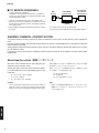
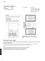
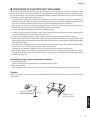
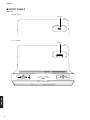
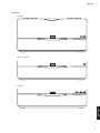
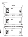
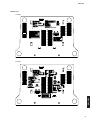
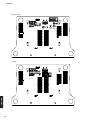
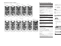
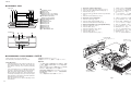
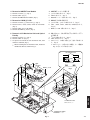
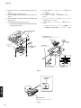
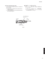
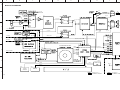
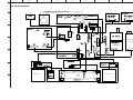
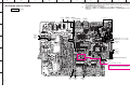
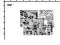
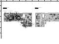
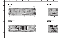
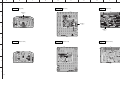
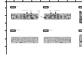
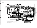
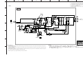
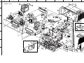
DESKTOP AUDIO SYSTEM
TSX-100
SERVICE MANUAL
IMPORTANT NOTICE
This manual has been provided for the use of authorized YAMAHA Retailers and their service personnel.
It has been assumed that basic service procedures inherent to the industry, and more specifically YAMAHA Products, are already
known and understood by the users, and have therefore not been restated.
WARNING:
Failure to follow appropriate service and safety procedures when servicing this product may result in personal
injury, destruction of expensive components, and failure of the product to perform as specified. For these reasons,
we advise all YAMAHA product owners that any service required should be performed by an authorized
YAMAHA Retailer or the appointed service representative.
IMPORTANT: The presentation or sale of this manual to any individual or firm does not constitute authorization, certification or
recognition of any applicable technical capabilities, or establish a principle-agent relationship of any form.
The data provided is believed to be accurate and applicable to the unit(s) indicated on the cover. The research, engineering, and
service departments of YAMAHA are continually striving to improve YAMAHA products. Modifications are, therefore, inevitable
and specifications are subject to change without notice or obligation to retrofit. Should any discrepancy appear to exist, please
contact the distributor's Service Division.
WARNING:
Static discharges can destroy expensive components. Discharge any static electricity your body may have
accumulated by grounding yourself to the ground buss in the unit (heavy gauge black wires connect to this buss).
IMPORTANT: Turn the unit OFF during disassembly and part replacement. Recheck all work before you apply power to the unit.
■ CONTENTS
101079
TEST MODE ................................................................. 16
テストモード ................................................................... 17
BLOCK DIAGRAM ....................................................... 18
WIRING DIAGRAM ...................................................... 19
PRINTED CIRCUIT BOARDS ................................ 20–26
SCHEMATIC DIAGRAMS ...................................... 27–31
REPLACEMENT PARTS LIST .............................. 32–36
REMOTE CONTROL .............................................. 37–39
2008
All rights reserved.
This manual is copyrighted by YAMAHA and may not be copied or
redistributed either in print or electronically without permission.
P.O.Box 1, Hamamatsu, Japan
'08.03
TSX-100
TO SERVICE PERSONNEL ...................................... 2–4
PREVENTION OF ELECTROSTATIC DISCHARGE .... 5
FRONT PANELS ........................................................ 6–7
REAR PANELS ........................................................ 8–10
REMOTE CONTROL PANELS .................................... 11
SPECIFICATIONS / 参考仕様 ........................................ 11
INTERNAL VIEW ......................................................... 12
DISASSEMBLY PROCEDURES / 分解手順 ........... 12–15
TSX-100
■ TO SERVICE PERSONNEL
WALL
OUTLET
1. Critical Components Information
Components having special characteristics are marked s
and must be replaced with parts having specifications equal
to those originally installed.
2. Leakage Current Measurement (For 120V Models Only)
When service has been completed, it is imperative to verify
that all exposed conductive surfaces are properly insulated
from supply circuits.
●
Meter impedance should be equivalent to 1500 ohms shunted
by 0.15µF.
EQUIPMENT
UNDER TEST
AC LEAKAGE
TESTER OR
EQUIVALENT
INSULATING
TABLE
●
●
Leakage current must not exceed 0.5mA.
Be sure to test for leakage with the AC plug in both polarities.
WARNING: CHEMICAL CONTENT NOTICE!
This product contains chemicals known to the State of California to cause cancer, or birth defects or other reproductive
harm.
DO NOT PLACE SOLDER, ELECTRICAL/ELECTRONIC OR PLASTIC COMPONENTS IN YOUR MOUTH FOR ANY
REASON WHAT SO EVER!
Avoid prolonged, unprotected contact between solder and your skin! When soldering, do not inhale solder fumes or expose
eyes to solder/flux vapor!
If you come in contact with solder or components located inside the enclosure of this product, wash your hands before
handling food.
About lead free solder / 無鉛ハンダについて
All of the P.C.B.s installed in this unit and solder joints are
soldered using the lead free solder.
本機に搭載されているすべての基板およびハンダ付けによる接合
部は無鉛ハンダでハンダ付けされています。
Among some types of lead free solder currently available,
it is recommended to use one of the following types for the
repair work.
無鉛ハンダにはいくつかの種類がありますが、修理時には下記の
ような無鉛ハンダの使用を推奨します。
•
•
•
Sn + Ag + Cu (tin + silver + copper)
Sn + Cu (tin + copper)
Sn + Zn + Bi (tin + zinc + bismuth)
Caution:
TSX-100
As the melting point temperature of the lead free solder is
about 30°C to 40°C (50°F to 70°F) higher than that of the lead
solder, be sure to use a soldering iron suitable to each solder.
2
・ Sn+Ag+Cu
(錫+銀+銅)
・ Sn+Cu(錫+銅)
・ Sn+Zn+Bi(錫+亜鉛+ビスマス)
注意:
無鉛ハンダの融点温度は通常の鉛入りハンダに比べ30∼40℃
程度高くなっていますので、それぞれのハンダに合ったハンダ
ごてをご使用ください。
TSX-100
WARNING: Lithium batteries
CAUTION
Danger of explosion if battery is incorrectly replaced.
Replace only with the same or equivalent type.
注意
正しい電池と交換しないと爆発が起きるおそれがあります。
同一型名または同等品以外の電池とは絶対に交換しないようにし
てください。
WARNING: Lithium batteries are dangerous because
ADVARSEL!
they can be exploded by improper handling. Observe the
following precautions when handling or replacing lithium
batteries.
• Leave lithium battery replacement to qualified service
personnel.
• Always replace with batteries of the same type.
• When installing on the PC board by soldering, solder
using the connection terminals provided on the battery
cells. Never solder directly to the cells. Perform the
soldering as quickly as possible.
• Never reverse the battery polarities when installing.
• Do not short the batteries.
• Do not attempt to recharge these batteries.
• Do not disassemble the batteries.
• Never heat batteries or throw them into fire.
Lithiumbatteri –Eksplosionsfare ved fejlagtig håndtering.
Udskiftning må kun ske med batteri af samme fabrikat og
type. Levér det brugte batteri tilbage til leverandøren.
VARNING
Explosionsfara vid felaktigt batteribyte. Använd samma
batterityp eller an ekvivalent typ som rekommenderas av
apparattillverkaren. Kassera använt batteri enligt
fabrikantens instruktion.
VAROITUS
Paristo voi räjähtää, jos se on virheellisesti asennettu.
Vaihda paristo ainoastaan laitevalmistajan suosittelemaan
tyyppiin. Hävitä käytetty peristo valmistajan ohjeiden
mukaisesti.
WARNING: Laser Safety
This product contains a laser beam component. This component may emit invisible, as well as visible radiation,
which may cause eye damage. To protect your eyes and skin from laser radiation, the following precautions must be
used during servicing of the unit.
1) When testing and/or repairing any component within the product, keep your eyes and skin more than 30 cm away from
the laser pick-up unit at all times. Do not stare at the laser beam at any time.
2) Do not attempt to readjust, disassemble or repair the laser pick-up, unless noted elsewhere in this manual.
3) CAUTION : Use of controls, adjustments or performance of procedures other than those specified herein may result in
hazardous radiation exposure.
Laser Emitting conditions:
1) When the top cover is removed, and the STANDBY/ON SW is turned to the “ON” position, the laser component will emit
a beam for several seconds to detect if a disc is present. During this time (5-10 sec.) the laser may radiate through the
lens of the laser pick-up unit. Do not attempt any servicing during this period!
If no disc is detected, the laser will stop emitting the beam. When a disc is loaded, you will not be exposed to any laser
emissions.
2) The laser power level can be adjusted with the VR on the pick-up PWB, however, this level has been set by the factory
prior to shipping from the factory. Do not adjust this laser level control unless instruction is provided elsewhere in this
manual. Adjustment of this control can increase the laser emission level from the device.
TSX-100
3
TSX-100
Laser Diode Properties
• Type
• Wave length
• Emission duration
GaAlAs
780 nm
continuous
• Laser output
max. 44.6 µW *
* This output is the value measured at a distance of about
200 mm (7.9 in) from the objective lens surface on the
optical pick-up block.
Warning for power supply
The primary side of the power supply carries live mains voltage when the player is connected to the mains even when
the player is switched off !
This primary area is not shielded so it is possible to touch copper tracks and/or components when servicing the player.
Service personnel have to take precautions to prevent touching this area or components in this area.
Note:
The screws on the DVD mechanism may never be touched, removed or re-adjusted.
Handle the DVD mechanism with care when the unit has to be exchanged!
TSX-100
The DVD mechanism is very sensitive for dropping or giving shocks.
4
TSX-100
■ PREVENTION OF ELECTROSTATIC DISCHARGE
Some semiconductor (solid state) devices can be damaged easily by static electricity. Such components commonly are called
Electrostatically Sensitive (ES) Devices. Examples of typical ES devices are integrated circuits and some field-effect transistors and semiconductor “chip” components. The following techniques should be used to help reduce the incidence of component damage caused by electro static discharge (ESD).
1. Immediately before handling any semiconductor component or semiconductor-equipped assembly, drain off any ESD on
your body by touching a known earth ground. Alternatively, obtain and wear a commercially available discharging ESD wrist
strap, which should be removed for potential shock reasons prior to applying power to the unit under test.
2. After removing an electrical assembly equipped with ES devices, place the assembly on a conductive surface such as
aluminum foil, to prevent electrostatic charge buildup or exposure of the assembly.
3. Use only a grounded-tip soldering iron to solder or unsolder ES devices.
4. Use only an anti-static solder removal device. Some solder removal devices not classified as “anti-static (ESD protected)”
can generate electrical charge sufficient to damage ES devices.
5. Do not use freon-propelled chemicals. These can generate electrical charges sufficient to damage ES devices.
6. Do not remove a replacement ES device from its protective package until immediately before you are ready to install it. (Most
replacement ES devices are packaged with leads electrically shorted together by conductive foam, aluminum foil or comparable conductive material).
7. Immediately before removing the protective material from the leads of a replacement ES divice, touch the protective material to the chassis or circuit assembly into which the device will be installed.
CAUTION: Be sure no power is applied to the chassis or circuit, and observe all other safety precautions.
8. Minimize bodily motions when handling unpackaged replacement ES devices. (Otherwise harmless motion such as brushing together of your fabric clothes or lifting of your foot from a carpeted floor can generate static electricity (ESD) sufficient
to damage an ES device).
Grounding for electrostatic breakdown prevention
1. Human body grounding.
Use the antistatic wrist strap to discharge the static electricity from your body.
2. Work table grounding.
Put a conductive material (sheet) or steel sheet on the area where the optical pickup is placed and ground the sheet.
Caution:
The static electricity of your clothes will not be grounded through the wrist strap. So take care not to let your clothes touch the
optical pickup.
Anti-static wrist strap
1M-ohms
Conductive material
(sheet) or steel sheet
TSX-100
5
TSX-100
■ FRONT PANELS
Top view
R, B, G models
USB port
U, A, J models
TSX-100
iPod port
6
TSX-100
Front view
U model
R, A, G, J models
B model
TSX-100
7
TSX-100
■ REAR PANELS
Rear view
U model
PHONES
R, A, G, J models
TSX-100
B model
8
PORTABLE
TSX-100
Bottom view
U model
R model
TSX-100
9
TSX-100
A, B, G models
TSX-100
J model
10
TSX-100
■ REMOTE CONTROL PANELS
■ SPECIFICATIONS / 参考仕様
■ Player Section / プレーヤー部
– Black color –
U model
R model
A model
B model
G model
Playback system / 再生システム
.................................................................................. CD, CD-R/RW
*
■ Amplifier Section / アンプ部
※ 参考仕様および外観は予告なく変更されることがあります。
Type / スピーカー形式 ................................................. Twin SR-Bass
Magnetic shielding type / 防磁型
Driver / スピーカーユニット ....................................... 4.5 cm (1-3/4")
Titanium cone full-range x 2
Specifications are subject to change without notice due to product
improvements.
U .......... U.S.A. model
R .......... General model
A .......... Australian model
B .......... British model
G .......... European model
J ........... Japanese model
Minimum RMS output power per channel / 定格出力 (EIAJ)
..................................................................................... 10 W + 10 W
Input sensitivity/Impedance / 入力感度/インピーダンス
U, R, A, B, J models
PORTABLE ..................................................... 300 mV/47 k-ohms
G model
AUX ................................................................. 300 mV/47 k-ohms
Output level/Impedance / 出力レベル/インピーダンス
PHONES (volume max.)
U, R, A, G models ..................................................... 1 V/32 ohms
B, J models ........................................................... 470 V/32 ohms
“Swing Radiator Bass ™” is a trademark of YAMAHA CORPORATION.
「Swing Radiator Bass TM」は ヤマハ株式会社の登録商標です。
“iPod” is a trademark of Apple Inc., registered in the U.S. and other countries.
「iPod」
は、米国及びその他の国々で登録されたApple Inc.の商標または登録
商標です。
■ iPod Section / iPod部 [U, A, J models]
Support iPod models / 対応iPod
.............. iPod (Click and wheel), iPod mini, iPod nano, iPod touch
R
The XM name and related logos are registered trademarks of XM Satellite
Radio Inc.
■ FM Tuner Section / FMチューナー部
R model
A model
B model
G model
J model
(Black/Silver色、共通)
This receiver supports DAB tuning.
■ AM Tuner Section / AMチューナー部
Tuning range / 受信周波数範囲
U model ................................................................. 530 to 1,710 kHz
R, A, B, G, J models ............................................. 522 to 1,629 kHz
• DIMENSIONS / 寸法図
■ DAB Tuner Section [B model]
Tuning range (BAND III) ................................. 174 MHz to 240 MHz
Sensitivity ................................................................................ -95 dB
200
(7-7/8")
U model
Selectivity (for adjacent channel) .......................................... 40 dB
Antenna input (unbalanced) .............................................. 50 ohms
■ General / 総合
Power supply / 電源電圧
U model ................................................................ AC 120 V, 60 Hz
R, A, B, G, J models ................................ AC 100-240 V, 50/60 Hz
Power consumption / 消費電力
................................................................................................. 20 W
Standby power consumption / 待機時消費電力
.................................................................................... 1.0 W or less
Dimensions (W x H x D) / 寸法(幅×高さ×奥行き)
..................... 300 x 141.5 x 200 mm (11-13/16” x 5-9/16” x 7-7/8”)
141.5
(5-9/16")
– Silver color –
Tuning range / 受信周波数範囲
U model ............................................................... 87.5 to 107.9 MHz
R, A, B, G models ........................................... 87.50 to 108.00 MHz
J model ............................................................... 76.0 to 108.0 MHz
Weight / 質量
........................................................................ 2.7 kg (5 lbs. 15 oz.)
Finish / 仕上げ
Black color .................................................. U, R, A, B, G, J models
Silver color .................................................. U, R, A, B, G, J models
Accessories / 付属品
Remote control x 1, Battery (Lithium, CR2025) x 1, AM loop antenna
(2.0 m) x 1, Indoor FM antenna (1.5 m) x 1, Power cable (2 m) x 1,
Indoor DAB antenna (2.0 m) x 1 (B model)
300
(11-13/16")
Unit: mm (inch)
単位:mm(インチ)
11
TSX-100
■ INTERNAL VIEW
Top view
1 2 3
45
1
2
3
4
6
5
7
8
6
7
8
9
0
A
B
C
D
SPEAKER L ASS'Y
SMPS P.C.B.
MAIN (1) P.C.B.
MAIN (4) P.C.B. (U, A, J models)
MAIN (6) P.C.B. (R, B, G models)
DAB MODULE (B model)
MAIN (7) P.C.B. (B model)
AM/FM TUNER MODULE
MAIN (2) P.C.B.
SPEAKER R ASS'Y
MAIN (8) P.C.B.
MAIN (3) P.C.B.
MAIN (5) P.C.B.
MAIN (9) P.C.B.
MAIN (10) P.C.B.
CD MECHANISM UNIT
Front view
9
0
A
1. Removal of Rear Cabinet Ass’y
1. リアキャビネットASSYの外し方
a.
b.
c.
d.
Remove 2 screws (1) and 6 screws (2). (Fig. 1)
Pull out the rear cabinet rearward slowly. (Fig. 1)
Remove CN17. (Fig. 1)
Remove screw (3) and then remove the ground lead.
(Fig. 1)
e. Remove the rear cabinet ass’y. (Fig. 1)
a.
b.
c.
d.
e.
2. Removal of Front Panel Unit
2. フロントパネルユニットの外し方
a. Remove 2 screws (4). (Fig. 1)
b. Remove CN18, CN82 and CN84. (Fig. 1)
c. Remove the front panel unit forward. (Fig. 1)
a. 4のネジ2本を外します。(Fig. 1)
b. CN18、CN82、CN84を外します。(Fig. 1)
c. フロントパネルユニットを前方へ取り外します。
(Fig. 1)
3. Removal of Speaker L Ass’y and Speaker R Ass’y
3. スピーカーL ASSY、スピーカーR ASSYの外し方
a.
b.
c.
d.
e.
f.
a.
b.
c.
d.
e.
f.
Remove 3 screws (5). (Fig. 1)
Remove CN83. (Fig. 1)
Remove the speaker L ass’y. (Fig. 1)
Remove 3 screws (6). (Fig. 1)
Remove CN85. (Fig. 1)
Remove the speaker R ass’y. (Fig. 1)
1のネジ2本、2のネジ6本を外します。(Fig. 1)
リアキャビネットを後方に引き出します。(Fig. 1)
CN17を外します。(Fig. 1)
3のネジ1本を外し、アース線を外します。(Fig. 1)
リアキャビネットASSYを取り外します。(Fig. 1)
5のネジ3本を外します。(Fig. 1)
CN83を外します。(Fig. 1)
スピーカーL ASSYを取り外します。(Fig. 1)
6のネジ3本を外します。(Fig. 1)
CN85を外します。(Fig. 1)
スピーカーR ASSYを取り外します。(Fig. 1)
B
Front panel unit
フロントパネルユニット
CN83
CN82
CN85
Speaker L ass'y
スピーカーL ASSY
CN84
5
D
C
5
CN18
■ DISASSEMBLY PROCEDURES / 分解手順
(Remove parts in the order as numbered.)
Disconnect the power cable from the AC outlet.
Safety Measures
安全対策
•
・ この製品の内部には高電圧部分があり危険です。修理
の際は、絶縁性の手袋を使用するなどの安全対策を
行ってください。
・ SMPS(2)P.C.B.のC971には電源をOFFにした後も電
荷が残り、高電圧が維持されており危険です。
修理作業前に放電用抵抗(5 kΩ/10 W)をコンデンサの
端子間に接続して放電してください。放電所用時間は
約30秒間です。
また、修理後も同じ方法で放電してください。
•
12
Some internal parts in this product contain high voltages and are dangerous. Be sure to take safety measures during servicing, such as wearing insulating
gloves.
C971 on the SMPS (2) P.C.B. is dangerous even after
the power is turned off because an electric charge remains and a high voltage continues to exist there.
Before starting any repair work, perform discharge by
connecting a discharge resistor (5k-ohms/10 W) between terminals of the capacitor. The time required for
discharging is about 30 seconds.
After the repair work, also perform discharge in the
same manner.
3
CN17
(番号順に部品を取り外してください。)
AC電源コンセントから、電源コードを抜いてください。
2
2
6
4
6
Speaker R ass'y
スピーカーR ASSY
Ground lead
アース線
2
Fig. 1
Rear cabinet ass'y
リアキャビネットASSY
1
TSX-100
4. Removal of AM/FM Tuner Module
4. AM/FMチューナーの外し方
a. Remove 2 screws (7). (Fig. 2)
b. Remove CN12. (Fig. 2)
c. Remove the AM/FM tuner module. (Fig. 2)
a. 7のネジ2本を外します。(Fig. 2)
b. CN12を外します。(Fig. 2)
c. AM/FMチューナーを取り外します。(Fig. 2)
5. Removal of MAIN(1) P.C.B.
5. MAIN(1)P.C.B.の外し方
a. Remove 4 screws (8) and screw (9). (Fig. 2)
b. Remove CN11, CN35, CN42, CN91-93 and CN95.
(Fig. 2)
c. Remove CN15. (Fig. 2) (B model)
d. Remove the MAIN (1) P.C.B.. (Fig. 2)
a. 8のネジ4本、9のネジ1本を外します。(Fig. 2)
b. CN11、CN35、CN42、CN91-93、CN95を外します。
(Fig. 2)
c. MAIN(1)P.C.B.を取り外します。(Fig. 2)
6. Removal of CD Mechanism Unit and Optical
Pick-Up
6. CDメカユニットおよびオプティカルピックアッ
プの外し方
a. Remove 4 screws (0). (Fig. 2)
b. Remove CN31-33. (Fig. 2)
c. Lift up the rear side of the CD mechanism unit, then
remove it rearward. (Fig. 2)
a. 0のネジ4本を外します。(Fig. 2)
b. CN31-33を外します。(Fig. 2)
c. CDメカユニットの後ろを持ち上げ、後方へ取り外しま
す。(Fig. 2)
*
※ CDメカユニットを取り付ける場合、カード電線は
Fig. 3に示すように取り付けます。
When installing the CD mechanism unit, install the
flexible flat cable as shown in Fig. 3.
*
CD mechanism unit
CN31
CN31
Flexible flat cable
CN95
CN35
8
OK
MAIN (1) P.C.B.
CN42
CN91
NG
Fig. 3
0
CN11
CN15
CN12 (B model)
9
0
0
CN92
CN31
CN93
CN33
7
TSX-100
CD mechanism unit
CDメカユニット
CN32
AM/FM tuner module
AM/FMチューナー
Fig. 2
13
TSX-100
d. A のネジ4本を外し、ドライブユニットを取り外しま
す。(Fig. 4)
e. カード電線を外します。(Fig. 4)
f. ギアAストッパーを外し、ギアAを取り外します。
(Fig. 4)
g. スレッドシャフトストッパーを外し、スレッドシャフ
トを取り外します。(Fig. 4)
h. オプティカルピックアップユニットを取り外します。
(Fig. 4)
d. Remove 4 screws (A) and then remove the drive unit.
(Fig. 4)
e. Remove flexible flat cable. (Fig. 4)
f. Remove stopper gear A and then remove the gear A.
(Fig. 4)
g. Remove stopper sled shaft and then remove the sled
shaft. (Fig. 4)
h. Remove the optical pick-up unit. (Fig. 4)
* Never touch the potentiometer installed to the optical pick-up unit. (Fig. 5)
※ オプティカルピックアップユニットに搭載されてい
る可変抵抗は、絶対に触らないでください。
(Fig. 5)
CD mechanism unit
CDメカユニット
Optical pick-up unit
オプティカルピックアップユニット
Gear A
ギアA
Drive unit
ドライブユニット
A
Sled shaft
スレッドシャフト
Flexible flat cable
カード電線
A
Stopper sled shaft
スレッドシャフトストッパー
Fig. 4
TSX-100
Potentiometer
可変抵抗
Optical pick-up unit
オプティカルピックアップユニット
Fig. 5
14
Stopper gear A
ギアAストッパー
TSX-100
● How to manually eject a disc
● 手動でディスクを取り出す方法
挿入したディスクが取り出せない場合、手動で取り出
すことができます。
a. CDメカユニットを取り外します。(分解手順参照)
b. ディスクが取り出せるまで、ローディングギアを矢
印の方向に回します。(Fig. 6)
If the inserted disc cannot be ejected, it is possible to
eject it manually.
a. Remove the CD mechanism unit. (Refer to Disassembly Procedures)
b. Turn the loading gear in the arrow direction until the
disc is ejected. (Fig. 6)
CD mechanism unit
CDメカユニット
Disc
ディスク
Left side
左側
Loading gear
ローディングギア
Fig. 6
TSX-100
15
TSX-100
■ TEST MODE
The firmware version is displayed.
● Starting Service Mode
a. Connect the power cable of this unit to the AC power outlet.
b. Press the “INPUT/SNOOZE” key of this unit to turn on the power.
c. Press the “INPUT/SNOOZE” key of this unit repeatedly to select the CD.
Make sure that [No Disc] is displayed.
* While the disc is being played, press the “A/F (STOP/EJECT)” key to eject the disc.
d. While pressing the “MUTE” key of this unit, press the “A /F (STOP/EJECT)” key of this unit.
The SERVICE mode is activated and each firmware version is displayed at about 5 seconds intervals.
This is displayed when the SERVICE mode is activated.
SERVICE MODE
HOST VER
The firmware version of the main microprocessor is displayed.
071018-03U/U
About 5 seconds
Destination
DSP VER
The firmware version of DSP is displayed.
07 10 16 01
About 5 seconds
USB VER
xx xx xx xx
The firmware version of USB is displayed.
(R, B, G models)
About 5 seconds
DAB VER
xx xx xx xx
The firmware version of DAB is displayed.
(B model)
About 5 seconds
3:53PM
Ordinary display.
No Disc
e. Press the “POWER OFF” key of this unit to turn off the power.
f. Disconnect the power cable of this unit from the AC power outlet.
● Starting Factory Reset
TSX-100
All
a.
b.
c.
16
settings are returned to initial settings.
Activate the Service Mode.
While the firmware versions are displayed, press and hold the “INPUT/SNOOZE” key for longer than 4 seconds.
[FACTORY SET] is displayed and the power is turned off automatically in about 4 seconds.
TSX-100
■ テストモード
ファームウェアバージョンを表示します。
● サービスモードの起動
a. 本機の電源コードをACコンセントに接続します。
b. 本機の“INPUT/SNOOZE”キーを押し、電源オンします。
c. 本機の“INPUT/SNOOZE”キーを繰り返し押して、CDを選択します。
[No Disc]が表示されていることを確認します。
※ ディスクが再生されている場合は、本機の“A/F(STOP/EJECT)”キーを押し、ディスクを取り出します。
d. 本機の“MUTE”キーを押しながら“A /F(STOP/EJECT)”キーを押します。
サービスモードが起動し、各ファームウェアバージョンが約5秒間隔で表示されます。
サービスモード起動時
SERVICE MODE
HOST VER
メインマイコンのファームウェアバージョンが表示されます。
071018-03U/U
約5秒間
仕向け表示
DSP VER
DSPのファームウェアバージョンが表示されます。
07 10 16 01
約5秒間
3:53PM
通常表示
No Disc
e. 本機の“POWER OFF”キーを押し、電源オフします。
f. ACコンセントから本機の電源コードを抜きます。
● ファクトリーリセットの起動
すべての設定を初期設定に戻します。
a. サービスモードを起動します。
b. ファームウェアバージョンを表示している間に、“INPUT/SNOOZE”キーを4秒以上押し続けます。
c. [FACTORY SET]が表示され、約4秒後に自動で電源オフします。
17
A
B
C
D
E
F
G
H
I
J
TSX-100
1
■ BLOCK DIAGRAM
AM/FM
IC53
RDS_DATA
MICROPROCESSOR
1,3
PHONES
IC14
2
RY52
HP_ON
2,15
IC21
3,5
5,14
3,13
1,7
ADL_SDTO
1,2
2
9
4
IC61
R, A, G, J models
3
iPod
27,28
3,5
1,7
1,12
U, B models
16,17 3
29-32
2-5
14
L
5
SPEAKERS
IC15
JK61
4,11
8,9
4
R
6
MICROPROCESSOR
3
IC22
RY51
U, A, J models
IC52
IC51
MICROPROCESSOR
JK71
37
IC71
U model
CD_SDTO1
XM_SDTO
AMP13V
SP_ON
2
DAB_SDTO
DAB/XM_SDTO
3
27
IC16
4
MICROPROCESSOR
USB (R, B, G models)
B model
+3.3VD
USBD+/13
79,80
+5VD
IC11
JK41
12
CD MECHANISM UNIT
AM/FM
TUNER
IC33
IC41
5
(MAIN)
MICROPROCESSOR
V_PROTECT
99
6 BEEP
iPod DOCK
(U, A, J models)
R, B, G models
IC31
9
69
XM
(U model)
62
5,11
POWER H
70
DAB
(B model)
AC IN
60,61,65,66
88
35
3,5,10,11
9,10
AC
IC12
85-87,95-98
6
91
S801-813
SENSOR
KEY0-2
PANEL KEYS
AMP13V
REMOTE
RC82
ROOM
SENSOR
(AMP)
FL81
RC81
REMOTE
7
MAIN
18
• See page 27-30 →
SCHEMATIC DIAGRAM
SMPS
• See page 31 →
SCHEMATIC DIAGRAM
A
B
C
D
E
F
G
H
I
J
TSX-100
1
■ WIRING DIAGRAM
(Writing port)
MAIN (4) P.C.B.
MAIN (6) P.C.B.
CD MECHANISM
UNIT
MAIN (2) P.C.B.
2
R, B, G models
(Writing port)
3
U, A, J models
SMPS P.C.B.
AM/FM TUNER
MODULE
4
MAIN (7) P.C.B.
B model
MAIN (1) P.C.B.
5
MAIN (5) P.C.B.
MAIN (9) P.C.B.
MAIN (8) P.C.B.
6
SPEAKER R ASS'Y
SPEAKER L ASS'Y
MAIN (10) P.C.B.
7
MAIN (3) P.C.B.
19
A
B
C
D
E
F
G
H
I
J
TSX-100
1
Note) The electrical parts available as servicing parts are those in the replacement parts list only.
When replacement of any electrical part other than those in the list is necessary, replace the P.C.B.
assembly which includes that part.
■ PRINTED CIRCUIT BOARDS
注)
MAIN (1) (Top view)
2
AC IN
MAIN (3)
MAIN (2)
BN18
BN35
電気部品リストに記載されている電気部品のみ、サービス部品として供給できます。
電気部品リストに記載されていない電気部品の交換が必要な場合は、その電気部品を搭載している
「P.C.B. ASSY」
を交換
してください。
U model
PORTABLE
PHONES
XM
3
SMPS
CN92
SMPS
MAIN (4) BN16
MAIN (6) BN17
CN91
4
(U, A, J models)
(R, B, G models)
MAIN (2)
BN11
B model
MAIN (7)
BN15
(B model)
5
AM/FM TUNER MODULE
MAIN (2)
BN42
BAT1: 30H3A3H (B, G models)
6
CAUTION
Danger of explosion if battery is incorrectly replaced.
Replace only with the same or equivalent type.
7
20
SMPS
MAIN (8)
MAIN (9)
CN93
CN82
CN84
A
B
C
D
E
F
G
H
I
J
TSX-100
1
MAIN (1) (Bottom view)
2
3
4
5
6
7
21
A
B
C
D
E
F
G
TSX-100
1
MAIN (2) (Top view)
2
CD MECHANISM
UNIT
CD MECHANISM
UNIT
MAIN (2) (Bottom view)
(Writing port)
3
4
MAIN (1)
CN11
(Writing port)
5
MAIN (1)
MAIN (1)
CN42
CN35
CD MECHANISM
UNIT
6
7
22
H
I
J
A
B
C
D
E
F
G
H
I
J
TSX-100
1
MAIN (3) (Top view)
MAIN (4) (Top view)
U, A, J models
MAIN (8)
MAIN (9)
BN87
BN88
2
iPod
3
MAIN (5)
MAIN (1)
MAIN (10)
BN86
CN18
BN89
MAIN (1)
CN17
4
MAIN (3) (Bottom view)
MAIN (4) (Bottom view)
U, A, J models
5
6
7
23
A
B
C
D
E
F
G
H
I
TSX-100
1
MAIN (5) (Top view)
MAIN (6) (Top view)
MAIN (7) (Top view)
R, B, G models
B model
MAIN (3)
CN86
USB
2
MAIN (1)
CN17
3
INPUT/SNOOZE
MAIN (1)
CN15
4
MAIN (5) (Bottom view)
MAIN (6) (Bottom view)
R, B, G models
5
6
7
24
MAIN (7) (Bottom view)
B model
J
A
B
C
D
E
F
G
H
I
J
TSX-100
1
MAIN (8) (Top view)
2
MAIN (9) (Top view)
SPEAKER L ASS'Y
MAIN (1)
MAIN (3)
MAIN (1)
BN84
CN87
BN82
MAIN (10) (Top view)
SPEAKER R ASS'Y
MAIN (3)
CN88
3
MAIN (3)
CN89
4
MAIN (8) (Bottom view)
MAIN (9) (Bottom view)
MAIN (10) (Bottom view)
5
6
7
25
A
B
C
D
E
F
G
H
I
TSX-100
1
SMPS (Side A)
SMPS (Side B)
2
MAIN (1)
MAIN (1)
BN91
BN93
3
10 W
5 k-ohms
4
5
6
MAIN (1)
BN92
Safety Measures
安全対策
•
・ この製品の内部には高電圧部分があり危険です。修理の際は、絶縁性の手袋を使用するなどの安全対策を行ってください。
・ SMPS(2)P.C.B.のC971には電源をOFFにした後も電荷が残り、高電圧が維持されており危険です。
修理作業前に放電用抵抗(5 kΩ/10 W)をコンデンサの端子間に接続して放電してください。放電所用時間は約30秒間です。
また、修理後も同じ方法で放電してください。
•
7
26
Some internal parts in this product contain high voltages and are dangerous. Be sure to take safety measures during servicing, such as
wearing insulating gloves.
C971 on the SMPS (2) P.C.B. is dangerous even after the power is turned off because an electric charge remains and a high voltage
continues to exist there.
Before starting any repair work, perform discharge by connecting a discharge resistor (5k-ohms/10 W) between terminals of the capacitor. The time required for discharging is about 30 seconds.
After the repair work, also perform discharge in the same manner.
J
A
B
C
D
E
F
G
H
I
J
TSX-100
1
Note) The electrical parts available as servicing parts are those in the replacement parts list only.
When replacement of any electrical part other than those in the list is necessary, replace the P.C.B.
assembly which includes that part.
■ SCHEMATIC DIAGRAMS
注)
MAIN 1/4
電気部品リストに記載されている電気部品のみ、サービス部品として供給できます。
電気部品リストに記載されていない電気部品の交換が必要な場合は、その電気部品を搭載している
「P.C.B. ASSY」
を交換
してください。
3
B4
to MAIN (1)_CN18
Page 28
iPod
Page 28
iPod IN
to MAIN (1)_CN17
B6
2
MAIN (3)
MAIN (10)
U, A, J models
MAIN (4)
SPEAKER OUT
MAIN (8)
MAIN (9)
4
J2
SPEAKERS L
ASS'Y
Page 28
B6
Page 28
MAIN (5)
5
6
SPEAKERS R
ASS'Y
USB IN
USB
MAIN (6)
XM
U model
★ Components having special characteristics are marked s and must be replaced with parts
having specifications equal to those originally installed.
★ Schematic diagram is subject to change without notice.
7
J2
to MAIN (1)_BN82
to MAIN (1)_CN17
Page 28
to MAIN (1)_BN84
★ s印のある部品は、安全性確保部品を示しています。部品の交換が必要な場合、パーツリスト
に記載されている部品を使用してください。
★ 本回路図は標準回路図です。改良のため予告なく変更することがございます。
MAIN (1)
B model
MAIN (7)
Page 28
F7
to MAIN (1)_CN15
27
A
B
C
D
E
F
G
H
I
J
TSX-100
1
MAIN 2/4
MAIN (1)
PHONES
SPEAKER OUT
2
Page 27
PORTABLE IN
G4
to MAIN (8)_CN82
PORTABLE
Page 27
I4
to MAIN (9)_CN84
ANALOG IN
3
Page 31
H3
to SMPS_CN93
Page 30
MIX IN
to AM/FM TUNER MODULE
I3
to MAIN (1)_CN97
4
iPod IN
Page 27
G3
to MAIN (3)_BN18
Page 29
B3
to MAIN (2)_BN35
AD IN
5
MICROPROCESSOR
Page 27
E3
to MAIN (4)_BN16
(U, A, J models)
Page 27
Page 30
I4
to MAIN (1)_CN98
I5
CD/USB IN
to MAIN (6)_BN17
(R, B, G models)
6
BAT1: 30H3A3H (B, G models)
CAUTION
Danger of explosion if battery is incorrectly replaced.
Replace only with the same or equivalent type.
USB IN
Page 27
7
Page 29
G7
to MAIN (2)_BN42
28
Page 29
E2
to MAIN (2)_BN11
H7
to MAIN (7)_BN15
(B model)
★ Components having special characteristics are marked s and must be replaced with parts
having specifications equal to those originally installed.
★ Schematic diagram is subject to change without notice.
★ s印のある部品は、安全性確保部品を示しています。部品の交換が必要な場合、パーツリスト
に記載されている部品を使用してください。
★ 本回路図は標準回路図です。改良のため予告なく変更することがございます。
A
B
C
D
E
F
G
H
I
J
TSX-100
1
MAIN 3/4
Page 28
E7
to MAIN (1)_CN11
2
USB IN
to CD MECHANISM UNIT
to CD MECHANISM UNIT
3
Page 28
J5
to MAIN (1)_CN35
to CD MECHANISM UNIT
4
CD IN
5
CD/USB IN
Page 28
C7
to MAIN (1)_CN42
MAIN (2)
6
(Writing port)
Page 28
C7
to MAIN (1)_CN42
7
★ Components having special characteristics are marked s and must be replaced with parts
having specifications equal to those originally installed.
★ Schematic diagram is subject to change without notice.
★ s印のある部品は、安全性確保部品を示しています。部品の交換が必要な場合、パーツリスト
に記載されている部品を使用してください。
★ 本回路図は標準回路図です。改良のため予告なく変更することがございます。
29
A
B
C
D
E
F
G
H
I
J
TSX-100
1
MAIN 4/4
MAIN (1)
Page 31
B3
to SMPS_CN91
Page 31
D5
to SMPS_CN92
2
3
AC IN
Page 28
J4
to MAIN (1)_PW1-5
4
Page 28
J4
to MAIN (1)_PW6-18
5
6
★ Components having special characteristics are marked s and must be replaced with parts
having specifications equal to those originally installed.
★ Schematic diagram is subject to change without notice.
7
★ s印のある部品は、安全性確保部品を示しています。部品の交換が必要な場合、パーツリスト
に記載されている部品を使用してください。
★ 本回路図は標準回路図です。改良のため予告なく変更することがございます。
30
A
B
C
D
E
F
G
H
I
J
TSX-100
★ Components having special characteristics are marked s and must be replaced with parts
having specifications equal to those originally installed.
★ Schematic diagram is subject to change without notice.
1
★ s印のある部品は、安全性確保部品を示しています。部品の交換が必要な場合、パーツリスト
に記載されている部品を使用してください。
★ 本回路図は標準回路図です。改良のため予告なく変更することがございます。
SMPS
SMPS
2
5 k-ohms
10 W
3
to MAIN (1)_BN92
Page 30
E2
Page 28
J3
to MAIN (1)_BN93
4
5
Page 30
D3
to MAIN (1)_BN91
6
Safety Measures
安全対策
•
・ この製品の内部には高電圧部分があり危険です。修理の際は、絶縁性の手袋を使用するなどの安全対策を行ってください。
・ SMPS(2)P.C.B.のC971には電源をOFFにした後も電荷が残り、高電圧が維持されており危険です。
修理作業前に放電用抵抗(5 kΩ/10 W)をコンデンサの端子間に接続して放電してください。放電所用時間は約30秒間です。
また、修理後も同じ方法で放電してください。
•
7
Some internal parts in this product contain high voltages and are dangerous. Be sure to take safety measures during servicing, such as
wearing insulating gloves.
C971 on the SMPS (2) P.C.B. is dangerous even after the power is turned off because an electric charge remains and a high voltage
continues to exist there.
Before starting any repair work, perform discharge by connecting a discharge resistor (5k-ohms/10 W) between terminals of the capacitor. The time required for discharging is about 30 seconds.
After the repair work, also perform discharge in the same manner.
31
TSX-100
■ REPLACEMENT PARTS LIST
P.C.B. MAIN
• ELECTRICAL COMPONENT PARTS
Note) The electrical parts available as servicing parts are those in the replacement parts list only.
When replacement of any electrical part other than those in the list is necessary, replace the P.C.B.
assembly which includes that part.
WARNING
● Components having special characteristics are marked s and must be replaced with parts having specifications
equal to those originally installed.
注)
● s印のある部分は、安全確保部品を示しています。部品の交換が必要な場合、パーツリストに記載されている部品を使用してください。
● 部品価格ランクは、予告なく変更することがあります。
ABBREVIATIONS IN THIS LIST ARE AS FOLLOWS:
C.A.EL.CHP
C.CE
C.CE.ARRAY
C.CE.CHP
C.CE.ML
C.CE.M.CHP
C.CE.SAFTY
C.CE.TUBLR
C.CE.SMI
C.EL
C.MICA
C.ML.FLM
C.MP
C.MYLAR
C.MYLAR.ML
C.PAPER
C.PLS
C.POL
C.POLY
C.PP
C.TNTL
C.TNTL.CHP
C.TRIM
CN
CN.BS.PIN
CN.CANNON
CN.DIN
CN.FLAT
CN.POST
COIL.MX.AM
COIL.AT.FM
COIL.DT.FM
COIL.MX.FM
COIL,OUTPT
DIOD.ARRAY
DIODE.BRG
DIODE.CHP
DIODE.VAR
DIOD.Z.CHP
DIODE.ZENR
DSCR.CE
FER.BEAD
FER.CORE
FET.CHP
FL.DSPLY
FLTR.CE
FLTR.COMB
FLTR.LC.RF
GND.MTL
GND.TERM
HOLDER.FUS
IC.PRTCT
JUMPER.CN
JUMPER.TST
L.DTCT
:
:
:
:
:
:
:
:
:
:
:
:
:
:
:
:
:
:
:
:
:
:
:
:
:
:
:
:
:
:
:
:
:
:
:
:
:
:
:
:
:
:
:
:
:
:
:
:
:
:
:
:
:
:
:
CHIP ALUMI.ELECTROLYTIC CAP
CERAMIC CAP
CERAMIC CAP ARRAY
CHIP CERAMIC CAP
MULTILAYER CERAMIC CAP
CHIP MULTILAYER CERAMIC CAP
RECOGNIZED CERAMIC CAP
CERAMIC TUBULAR CAP
SEMI CONDUCTIVE CERAMIC CAP
ELECTROLYTIC CAP
MICA CAP
MULTILAYER FILM CAP
METALLIZED PAPER CAP
MYLAR FILM CAP
MULTILAYER MYLAR FILM CAP
PAPER CAPACITOR
POLYSTYRENE FILM CAP
POLYESTER FILM CAP
POLYETHYLENE FILM CAP
POLYPROPYLENE FILM CAP
TANTALUM CAP
CHIP TANTALUM CAP
TRIMMER CAP
CONNECTOR
CONNECTOR,BASE PIN
CONNECTOR,CANNON
CONNECTOR,DIN
CONNECTOR,FLAT CABLE
CONNECTOR,BASE POST
COIL,AM MIX
COIL,FM ANTENNA
COIL,FM DETECT
COIL,FM MIX
OUTPUT COIL
DIODE ARRAY
DIODE BRIDGE
CHIP DIODE
VARACTOR DIODE
CHIP ZENER DIODE
ZENER DIODE
CERAMIC DISCRIMINATOR
FERRITE BEADS
FERRITE CORE
CHIP FET
FLUORESCENT DISPLAY
CERAMIC FILTER
COMB FILTER MODULE
LC FILTER,EMI
GROUND PLATE
GROUND TERMINAL
FUSE HOLDER
IC PROTECTOR
JUMPER CONNECTOR
JUMPER,TEST POINT
LIGHT DETECTING MODULE
L.EMIT
LED.DSPLY
LED.INFRD
MODUL.RF
PHOT.CPL
PHOT.INTR
PHOT.RFLCT
PIN.TEST
PLST.RIVET
R.ARRAY
R.CAR.
R.CAR.CHP
R.CAR.FP
R.FUS
R.MTL.CHP
R.MTL.FLM
R.MTL.OXD
R.MTL.PLAT
RSNR.CE
RSNR.CRYS
R.TW.CEM
R.CEMENT
SCR.BND.HD
SCR.BW.HD
SCR.CUP
SCR.TERM
SCR.TR
SUPRT.PCB
SURG.PRTCT
SW.TACT
SW.LEAF
SW.LEVER
SW.MICRO
SW.PUSH
SW.RT.ENC
SW.RT.MTR
SW.RT
SW.SLIDE
TERM.SP
TERM.WRAP
THRMST.CHP
TR.CHP
TR.DGT
TR.DGT.CHP
TRANS
TRANS.PULS
TRANS.PWR
TUNER.AM
TUNER.FM
TUNER.PK
VR
VR.MTR
VR.SW
VR.SLIDE
VR.TRIM
:
:
:
:
:
:
:
:
:
:
:
:
:
:
:
:
:
:
:
:
:
:
:
:
:
:
:
:
:
:
:
:
:
:
:
:
:
:
:
:
:
:
:
:
:
:
:
:
:
:
:
:
:
:
:
LIGHT EMITTING MODULE
LED DISPLAY
LED,INFRARED
MODULATOR,RF
PHOTO COUPLER
PHOTO INTERRUPTER
PHOTO REFLECTOR
PIN,TEST POINT
PLASTIC RIVET
RESISTOR ARRAY
CARBON RESISTOR
CHIP RESISTOR
FLAME PROOF CARBON RESISTOR
FUSABLE RESISTOR
CHIP METAL FILM RESISTOR
METAL FILM RESISTOR
METAL OXIDE FILM RESISTOR
METAL PLATE RESISTOR
CERAMIC RESONATOR
CRYSTAL RESONATOR
TWIN CEMENT FIXED RESISTOR
CEMENT RESISTOR
BIND HEAD B-TIGHT SCREW
BW HEAD TAPPING SCREW
CUP TIGHT SCREW
SCREW TERMINAL
SCREW,TRANSISTOR
SUPPORT,P.C.B.
SURGE PROTECTOR
TACT SWITCH
LEAF SWITCH
LEVER SWITCH
MICRO SWITCH
PUSH SWITCH
ROTARY ENCODER
ROTARY SWITCH WITH MOTOR
ROTARY SWITCH
SLIDE SWITCH
SPEAKER TERMINAL
WRAPPING TERMINAL
CHIP THERMISTOR
CHIP TRANSISTOR
DIGITAL TRANSISTOR
CHIP DIGITAL TRANSISTOR
TRANSFORMER
PULSE TRANSFORMER
POWER TRANSFORMER ASS’Y
TUNER PACK,AM
TUNER PACK,FM
FRONT-ENDTUNER PACK
ROTARY POTENTIOMETER
POTENTIOMETER WITH MOTOR
POTENTIOMETER WITH ROTARY SW
SLIDE POTENTIOMETER
TRIMMER POTENTIOMETER
*
*
*
*
*
*
*
*
*
*
*
*
*
*
*
*
*
*
*
*
*
*
*
*
*
*
*
*
*
*
*
*
電気部品リストに記載されている電気部品のみ、サービス部品として供給できます。
電気部品リストに記載されていない電気部品の交換が必要な場合は、その電気部品を搭載している
「P.C.B. ASSY」
を交換
してください。
Ref No.
Part No.
BAT1
C509
C520
C526
C527
C529
CX91
CX92
CY91-94
D814
F901
FH91-92
FL81
IC12
IC14
IC15
IC21
IC22
IC31
IC33
IC34
IC36
IC42
IC45
IC51
IC52
IC53
IC91
IC92
IC93
IC94
IC95
IC96
IC97
IC98
IC99
JK21
JK41
AAX88200
AAX88170
AAX88190
AAX88180
AAX88160
AAX87070
AAX88880
AAX88870
AAX88860
AAX88810
AAX88850
AAX88850
AAX88770
AAX88780
AAX88840
AAX88760
AAX87280
AAX87380
AAX87090
AAX86970
AAX86930
AAX88750
AAX77190
AAX86940
AAX87000
AAX83140
AAX87010
AAX86960
AAX83060
AAX83110
AAX86980
AAX86990
AAX87020
AAX88730
AAX81040
AAX80950
AAX86950
AAX81040
AAX81040
AAX81040
AAX77360
AAX77370
AAX87240
AAX83300
Description
P.C.B.
P.C.B.
P.C.B.
P.C.B.
P.C.B.
P.C.B.
BATTTERY
C.CHIP
C.CHIP
C.EL
C.CHIP
C.CHIP
C.PP
C.PP
C.CE
LED
FUSE
HOLDER
FL.DSPLY
IC
IC
IC
IC
IC
IC
IC
IC
IC
IC
IC
IC
IC
IC
IC
IC
IC
IC
IC
IC
IC
IC
IC
JACK
JACK
✻ New Parts * 新規部品
32
MAIN
MAIN
MAIN
MAIN
MAIN
MAIN
30H3A3H
2.2F
6.3V
22F
6.3V
2200uF
25V
1F
35V
1F
35V
F2E224KZE
F2E104KZE
2G102M10FF7
2-COLOR RED/BLUE
T2A 250V
FV891GIND
NR8576AAGET
AK5358AET
SN74LVC157APW-EL2
BA4560RF
HCF4052M013T
TC94A73FG
TA2125AFG
74LCX244T
KIA1117S15
RT9702APB
74ACT04MTR
STA320
STA515
NJM4556AL
SG5842JADZ
KIA431BAT
ICE3B0365J
ICE2B265
KIA431BAT
KIA431BAT
KIA431BAT
KIA7812API
KIA7912PI
PORTABLE
4P
Remarks
COP12002G
COP12002D
COP12002F
COP12002E
COP12002C
COP12002B
CAB30H3A3H
CCSJA0J2R2B
CCSJA0J220B
CCEA1EKLH222EKS
CCSJA1V1R0B
CCSJA1V1R0B
CCQF2E224KZE
HCQF2E104KZE
CCKDHS102ME
CVD1L0392S1B11MA402
KBA2C2000TLEY
KJCFC5S
CFLFV891GIND
CVINR8576AAGET
CVIAK5358AET
HVISN74LVC157AP
HVIBA4560RF
CVIHCF4052M013T
CVITC94A73FG
HVITA2125AFG
HVI74LCX244T
CVIKIA1117S15
CVIRT9702APB
HVI74ACT04MTR
CVISTA320
CVISTA515
HVINJM4556AL
CVISG5842JADZ
HVIKIA431BAT
CVIICE3B0365J
CVIICE2B265
HVIKIA431BAT
HVIKIA431BAT
HVIKIA431BAT
HVIKIA7812API
HVIKIA7912PI
HJJ2E027Z
CJJ9X003Y
Markets
J
U
R
A
B
G
BG
JRAG
RBG
RBG
部 品 名
PCB MAIN
PCB MAIN
PCB MAIN
PCB MAIN
PCB MAIN
PCB MAIN
リチウム電池
チップコンデンサ
チップコンデンサ
ケミコン
チップコンデンサ
チップコンデンサ
PPコン
PPコン
セラコン
LED
ヒューズ
ヒューズホルダー
VFD
IC
IC
IC
アンプIC
IC
IC
IC
IC
IC
IC
IC
IC
IC
IC
IC
IC
IC
IC
IC
IC
IC
電源IC
電源IC
ジャック
USB端子
ランク
07
04
03
03
TSX-100
P.C.B. MAIN and P.C.B. SMPS
*
*
*
*
*
*
*
*
*
*
*
*
*
*
*
*
Ref No.
Part No.
Description
Remarks
JK51
LF91
LF93
PC91
PC92
PC93
PC94
PC95
RC81
RC82
RY51
RY52
S801-813
TF91
TF92
TF93
TH91
V901
X101
X301
X401
AAX87240
AAX88910
AAX88910
AAX81120
AAX81120
AAX81120
AAX81120
AAX81120
AAX84540
AAX88920
AAX79390
AAX83560
AAX74630
AAX87490
AAX87470
AAX87480
AAX88820
AAX88890
AAX88940
AAX88930
AAX88950
JACK
FILTER
FILTER
IC.PHOTO
IC.PHOTO
IC.PHOTO
IC.PHOTO
IC.PHOTO
SENS.RC
SENS
RELAY
RELAY
SW. TACT
TRANS.PWR
TRANS.PWR
TRANS.PWR
THERM.
VARISTOR
RSNR.CRYS
RSNR.CRYS
RSNR.CRYS
PHONES
UU1116 20mH
UU1116 20mH
PC17L1CB
PC17L1CB
PC17L1CB
PC17L1CB
PC17L1CB
KSM603TH2E
PT337P11A
G5PA28
DC12V 2C2P
SKHV10910G
MAIN EER3541
SUB EFD2525
FL EE2020
DSC-8D13MSFB
SVC471D14A
20MHz
16.934MHz
9MHz
HJJ2E027Z
CLZ9Z065Z
CLZ9Z065Z
HVIPC17L1CB
HVIPC17L1CB
HVIPC17L1CB
HVIPC17L1CB
HVIPC17L1CB
CRVKSM603TH2E
CRVPT337P11A
CSL3A017ZU
CSL4A016ZU
CST1A012ZT
CLT9Z041ZE
CLT9Z039ZE
CLT9Z040ZE
KRT8D13MSFB
CRVSVC471D14A
HOX20000E220TF
HOX16934A120C
COX09000E150C
IC91
IC92
PC91
Q971
TF91
AAX87080
AAX88730
AAX81040
AAX81120
AAX88740
AAX87490
P.C.B.
IC
IC
IC.PHOTO
IC
TRANS.PWR
SMPS
SG5842JADZ
KIA431BAT
PC17L1CB
SPP11N60C3
EER3541
COP12011B
CVISG5842JADZ
HVIKIA431BAT
HVIPC17L1CB
CVISPP11N60C3
CLT9Z041ZE
Markets
JBG
RBG
部 品 名
ジャック
ラインフィルタ
ラインフィルタ
IC
IC
IC
IC
IC
リモコン受光器
光センサー
リレー
リレー
タクトスイッチ
電源トランス
電源トランス
電源トランス
サーミスタ
バリスタ
水晶振動子
水晶振動子
水晶振動子
ランク
04
04
01
PCB SMPS
IC
IC
IC
IC
電源トランス
✻ New Parts * 新規部品
33
A
B
C
D
E
F
G
H
I
J
TSX-100
1
•
OVERALL ASS’Y
154
155
113
11
151
155
106 (3)
13
161
161
2
155
5
160
155
106 (8)
4
154
152
6
161
15
106 (10)
3
8
3
161
172
106 (5)
155
155
106 (9)
3
155
7
19
18
155
106 (1)
154
112-2
155
171
152
159
R, B, G models
14
1
2
19
106 (6)
112
152
4
23
155
115
173
114
159
106 (2)
21
17
54
159
155
U, A, J models
155
5
112-1
107
20
155
11
151
52
162
158
B model
162
116
157
118
156
119
6
156
9
156
157
117
174
22
155
10
175
153
158
157
54
12
106 (4)
157
20
152
7
106 (7)
34
16
173
152
TSX-100
Ref No.
*
1
*
2
*
2
*
2
*
2
*
2
*
2
*
3
*
4
*
5
*
6
*
7
*
8
*
9
*
9
*
9
*
9
*
10
*
11
*
11
*
11
*
11
*
12
*
12
*
13
*
13
*
13
*
13
*
13
*
13
*
14
*
15
*
16
*
17
*
17
*
18
*
19
*
20
*
21
*
22
*
23
*
52
*
55
*
106
*
106
*
106
*
106
*
106
*
106
* s 107
*
112
112-1
112-2
*
113
*
113
*
114
Part No.
AAX87060
AAX87100
AAX89820
AAX89840
AAX87110
AAX89830
AAX89850
AAX88480
AAX87400
AAX87420
AAX88500
AAX87390
AAX87410
AAX88220
AAX88240
AAX88230
AAX87160
AAX87450
AAX89730
AAX89740
AAX89750
AAX89760
AAX88340
AAX88350
AAX87330
AAX88390
AAX88370
AAX87340
AAX88400
AAX88380
AAX88830
AAX88250
AAX88460
AAX88330
AAX88320
AAX88450
AAX88470
AAX89700
AAX89710
AAX89720
AAX88210
AAX87360
AAX88900
AAX88200
AAX88170
AAX88190
AAX88180
AAX88160
AAX87070
AAX87080
AAX86920
AAX82720
AAX78500
AAX90040
AAX87250
AAX90050
Description
FRONT PANEL ASS'Y
WINDOW
WINDOW
WINDOW
WINDOW
WINDOW
WINDOW
FUNCTION RUBBER
BUTTON
BUTTON
LENS BUTTON ASS'Y
BUTTON
BUTTON
COVER BOTTOM
COVER BOTTOM
COVER BOTTOM
COVER BOTTOM
FOOT
REAR CABINET ASS'Y
REAR CABINET ASS'Y
REAR CABINET ASS'Y
REAR CABINET ASS'Y
SLEEVE
SLEEVE
PLATE NAME
PLATE NAME
PLATE NAME
PLATE NAME
PLATE NAME
PLATE NAME
COVER SHIELD
CUSHION A
RUBBER A
EVA CUSHION
EVA CUSHION
RUBBER B
RUBBER C
CUSHION FRONT
CUSHION REAR L
CUSHION REAR R
INSULATOR
PLATE BOTTOM
BRACKET CD MECHANISM
P.C.B. ASS'Y
P.C.B. ASS'Y
P.C.B. ASS'Y
P.C.B. ASS'Y
P.C.B. ASS'Y
P.C.B. ASS'Y
P.C.B. ASS'Y
CD MECHANISM UNIT
OPTICAL PICK UP UNIT
BELT
SPEAKER L ASS'Y
SPEAKER L ASS'Y
SPEAKER R ASS'Y
✻ New Parts * 新規部品
BL
BL
BL
SI
SI
SI
POWER
SKIP
MUTE
PRESET
D21 t=2
BL
BL
SI
SI
BL
SI
BL
BL
BL
SI
SI
SI
MAIN
MAIN
MAIN
MAIN
MAIN
MAIN
SMPS
SLOT IN TYPE
KSS-213C
L
L
R
Remarks
CGW1A439ZA
CGU1A409Y
CGU1A409U
CGU1A409W
CGU1A409Z
CGU1A409V
CGU1A409X
CHG1A380
CBT1A1053ZC22
CBT1A1054ZC22
CBT1A1055
CBT1A1053YC22
CBT1A1054YC22
CKD1A064VK128
CKD1A064XK128
CKD1A064WK128
CKD1A064ZK128
CHG1A369
CKD1A065B27YA
CKD1A065B27ZA
CKD1A065W2YA
CKD1A065W2ZA
CMH1A281Y
CMH1A281Z
CGX1A393Y
CGX1A393W
CGX1A393U
CGX1A393Z
CGX1A393X
CGX1A393V
CMX1A233
CHG1A218Z
CHG1A400
CHG2A405
CHG1A405
CHG1A304Z
CHG1A401
CHG1A378
CHG1A379
CHG1A384
CMX1A234
CUA1A276
CMD1A640
COP12002G
COP12002D
COP12002F
COP12002E
COP12002C
COP12002B
COP12011B
CJDDL2130CCM
KSM2130CCM
9A07980900
CASTSX100JLSPK
CASTSX100LSPK
CASTSX100JRSPK
Markets
JRAG
U
B
JRAG
U
B
J
U
R
ABG
JUA
RBG
JUA
RBG
RBG
RBG
JRAG
U
B
JRAG
U
B
JUA
RBG
J
U
R
A
B
G
J
URABG
J
部 品 名
フロントパネルASSY
ウィンドウ
ウィンドウ
ウィンドウ
ウィンドウ
ウィンドウ
ウィンドウ
ボタン受けゴム
ボタン
ボタン
レンズボタンASSY
ボタン
ボタン
ボトムカバー
ボトムカバー
ボトムカバー
ボトムカバー
脚
リアキャビネットASSY
リアキャビネットASSY
リアキャビネットASSY
リアキャビネットASSY
スリーブ
スリーブ
ネームプレート
ネームプレート
ネームプレート
ネームプレート
ネームプレート
ネームプレート
シールドカバー
クッションA
ラバーA
EVAクッション
EVAクッション
ラバーB
ラバーC
クッションFRONT
クッションREAR L
クッションREAR R
インシュレータ
プレート ボトム
ブラケット CDメカ
PCB MAIN
PCB MAIN
PCB MAIN
PCB MAIN
PCB MAIN
PCB MAIN
PCB SMPS
CDメカユニット
オプティカルピックアップ
ベルト
スピーカーL ASSY
スピーカーL ASSY
スピーカーR ASSY
ランク
05
05
Ref No. Part No.
*
*
*
*
*
*
*
*
*
*
*
*
*
*
*
*
*
*
*
*
*
*
114
115
115
115
115
116
116
116
116
117
118
119
151
151
152
153
154
154
155
156
157
158
159
160
161
162
171
171
172
173
174
175
AAX87260
AAX89690
AAX89800
AAX89680
AAX89810
AAX89960
AAX89950
AAX89940
AAX83400
AAX89790
AAX84530
AAX84550
AAX78380
AAX73500
AAX78380
AAX84370
AAX78400
AAX82020
AAX78400
AAX88260
AAX88300
AAX88270
AAX88280
AAX88290
AAX88310
AAX89890
AAX87150
AAX89900
AAX87140
AAX87130
AAX89970
AAX89980
Description
SPEAKER R ASS'Y
INLET
INLET
INLET
INLET
AM/FM TUNER MODULE
AM/FM TUNER MODULE
AM/FM TUNER MODULE
AM/FM TUNER MODULE
DAB MODULE
NUT DAB
WASHER
BIND HEAD B-TIGHT SCREW
BIND HEAD B-TIGHT SCREW
BIND HEAD B-TIGHT SCREW
BIND HEAD B-TIGHT SCREW
BIND HEAD P-TIGHT SCREW
BIND HEAD P-TIGHT SCREW
BIND HEAD P-TIGHT SCREW
CUSHION B
CUSHION C
CUSHION D
CUSHION E
CUSHION F
CUSHION G
HIMELON TAPE
FLEXIBLE FLAT CABLE
FLEXIBLE FLAT CABLE
FLEXIBLE FLAT CABLE
FLEXIBLE FLAT CABLE
FLEXIBLE FLAT CABLE
FLEXIBLE FLAT CABLE
Remarks
R
BL
BL
SI
SI
BL 3x8
SI 3x8
3x8
3x10
BL 3x10
SI 3x10
3x10
10x100x1
15x30x1
16x83x1
8x40x1
8x40x1
4x100x1
4x25x0.5
21P 100mm
21P 80mm
19P 150mm
11P 100mm
13P 100mm
11P 100mm
MFZN2B3
MFZN2W3
MFZN2B3
MFZN2B3
MFZN2B3
MFZN2W3
MFZN2B3
CASTSX100RSPK
HJJ8A003Z
CJJ8A004X
CJJ8A003Y
CJJ8A004Y
CNVMV016MA1-17
CNVMV014MA1-17
CNVMV014MA0-17
CNVMV114MA1-17
CNVFS2025V22A
CNE1A009
CNW1A038
CTB3+8JFZR
CTB3+8JFC
CTB3+8JFZR
CTB3+10JFZR
CTB3+10GFZR
CTB3+10GFC
CTB3+10GFZR
CHG1A389
CHG1A395
CHG1A391
CHG1A392
CHG1A392Z
CHG1A404
CHS1A163
CWC4F2A21A100B
CWC4F2A21A080B
CWC4F2A19A150B
CWC4F2A11A100B
CWC4C4A13B100B
CWCTSX100BN15
Markets
URABG
JRABG
U
JRABG
U
J
UR
A
BG
B
B
B
B
部 品 名
スピーカーR ASSY
INLET
INLET
INLET
INLET
AM/FMチューナー
AM/FMチューナー
AM/FMチューナー
AM/FMチューナー
DABモジュール
ナット
ワッシャー
バインドBタイトネジ
バインドBタイトネジ
バインドBタイトネジ
バインドBタイトネジ
バインドPタイトネジ
バインドPタイトネジ
バインドPタイトネジ
クッションB
クッションC
クッションD
クッションE
クッションF
クッションG
HIMELONテープ
カード電線
カード電線
カード電線
カード電線
カード電線
カード電線
ランク
15
01
01
01
01
01
01
04
✻ New Parts * 新規部品
35
A
B
C
D
E
F
G
H
I
J
TSX-100
1
•
ACCESSORIES
Ref No. Part No.
200
*
*
*
*
*
*
*
*
*
*
*
*
*
2
200-1
202
203
3
204 B model
*
*
*
*
*
*
205
4
*
*
R model
*
205
206
207
208
s
s
s
s
s
s
s
s
s
s
s
s
s
s
s
s
200
200
200
200
200
200
200
200
200
200
200
200-1
200-1
202
203
203
204
205
205
205
205
205
205
205
205
205
205
206
206
207
207
208
208
WN414800
WM472200
WM472500
WM472600
WM472400
WM472300
WK970700
WK971000
WK971100
WK970900
WK970800
AAX89770
AAX89780
AAX73180
AAX76680
AAX73240
AAX84630
AAX80650
AAX80620
AAX80630
AAX80680
AAX88530
AAX88540
AAX88510
AAX87460
AAX88550
AAX88520
AAX80670
AAX90080
AAX80640
AAX90060
AAX80660
AAX90070
Description
REMOTE CONTROL
REMOTE CONTROL
REMOTE CONTROL
REMOTE CONTROL
REMOTE CONTROL
REMOTE CONTROL
REMOTE CONTROL
REMOTE CONTROL
REMOTE CONTROL
REMOTE CONTROL
REMOTE CONTROL
BATTERY HOLDER
BATTERY HOLDER
AM LOOP ANTENNA
INDOOR FM ANTENNA
INDOOR FM ANTENNA
INDOOR DAB ANTENNA
POWER CABLE
POWER CABLE
POWER CABLE
POWER CABLE
POWER CABLE
POWER CABLE
POWER CABLE
POWER CABLE
POWER CABLE
POWER CABLE
POWER CABLE
POWER CABLE
POWER CABLE
POWER CABLE
POWER CABLE
POWER CABLE
LITHIUM BATTERY
5
(G)
(T)
(K)
(R)
6
7
36
✻ New Parts * 新規部品
BL, SI
BL
BL
BL
BL
BL
SI
SI
SI
SI
SI
BL
SI
2.0m
1.5m
1.5m
2.0m
BL 2m
BL 2m
BL 2m
BL 2m
BL 2m
SI 2m
SI 2m
SI 2m
SI 2m
SI 2m
BL 2m
SI 2m
BL 2m
SI 2m
BL 2m
SI 2m
CR2025
Remarks
1pc
1pc
1pc
1pc
1pc
1pc
1pc
1pc
1pc
1pc
1pc
1pc
1pc
1pc
1pc
1pc
1pc
1pc
1pc
1pc
1pc
Markets
J
U
R
A
B
G
U
R
A
B
G
103RRS-162-01E URABG
103RRS-162-50E
CSA1A020Z
CSA1A019Z
J
CSA1A018Z
URABG
CSA1A272
B
CJA2J091Z
J
CJA2A085Z
U
CJA2B020Z
RG
CJA2S088Z
A
CJA2E079Z
B
CJA2J091Y
J
CJA2A085Y
U
CJA2B020Y
RG
CJA2S088Y
A
CJA2E079Y
B
CJA2N078Z
R
CJA2N078Y
R
CJA2D089Z
R
CJA2D089Y
R
CJA2L090Z
R
CJA2L090Y
R
部 品 名
リモコン
リモコン
リモコン
リモコン
リモコン
リモコン
リモコン
リモコン
リモコン
リモコン
リモコン
電池蓋
電池蓋
AMループアンテナ
FM簡易アンテナ
FM簡易アンテナ
DABワイヤアンテナ
電源コード
電源コード
電源コード
電源コード
電源コード
電源コード
電源コード
電源コード
電源コード
電源コード
電源コード
電源コード
電源コード
電源コード
電源コード
電源コード
リチウム電池
ランク
04
03
03
07
TSX-100
■ REMOTE CONTROL
•
SCHEMATIC DIAGRAM
KEY No.
XX
=
JP1 to JP6: Not mounted
R1
1 ohm, 1/4 W
JP1
JP2
JP3
JP4
JP5
JP6
D1
MIE-554A2
41
R2
Q1
C1
+
27 ohms, 1/10 W
2SC3440-T112
33
34
35
36
37
38
39
27
28
29
30
31
32
23
24
47µF
25
T5
17
18
19
20
21
9
10
11
12
13
14
15
16
1
2
3
4
5
6
7
8
T3
T2
20
19
VDD
CARR
18
D0
Vss
1
C2
17
16
D1
D2
15
D3
14
D4
13
12
D5
D6
11
D7
M34283G2GP–U1/W5
Z–N0102–86009#1X
IC1
3.0 V
T4
E2
2
E1
3
XIN
4
XOUT
X1
5
E0
6
G0
7
G1
8
G2
9
G3
10
0.1µF
4.00 MHz
•
PANELS
– Black color –
U model
R model
A model
B model
G model
TSX-100
37
TSX-100
•
KEY LAYOUT
– Silver color –
U model
R model
A model
1
2
3
4
5
6
7
8
9
10
11
12
13
14
15
16
17
18
19
20
23
27
B model
G model
24
21
25
28
29
30
31
32
33
34
35
36
37
38
39
J model
TSX-100
(Black/Silver色、共通)
38
41
TSX-100
•
KEY CODE
Key
No.
U model
1
STANDBY/ON
ALARM /
2
ON/OFF
R model
STANDBY/ON
ALARM /
ON/OFF
Key Name
A model
B model
STANDBY/ON STANDBY/ON
ALARM /
ALARM /
ON/OFF
ON/OFF
G model
STANDBY/ON
ALARM /
ON/OFF
3
DIMMER
DIMMER
DIMMER
DIMMER
DIMMER
4
TIME ADJ
TIME ADJ
TIME ADJ
TIME ADJ
TIME ADJ
SLEEP
SLEEP
SLEEP
SLEEP
SLEEP
TIMER
TIMER
TIMER
TIMER
TIMER
1
2
3
4
5
6
7
8
9
0
TONE
EQ
TIME/INFO
PRESET / H
DISPLAY
TUNE / Q
ENTER
1
2
3
4
5
6
7
8
9
0
TONE
EQ
TIME/INFO
PRESET / H
DISPLAY
TUNE / Q
ENTER
1
2
3
4
5
6
7
8
9
0
TONE
EQ
TIME/INFO
PRESET / H
DISPLAY
TUNE / Q
ENTER
1
2
3
4
5
6
7
8
9
0
TONE
EQ
TIME/INFO
PRESET / H
DISPLAY
TUNE / Q
ENTER
5
6
7
1
8
2
9
3
10
4
11
5
12
6
13
7
14
8
15
9
16
0
17
TONE
18
EQ
19
TIME/INFO
20 PRESET/CH / H
21
DISPLAY
23 TUNE/CAT / Q
24
ENTER
25
W
RANDOM
27
28
G
SRCH MODE /
29
REPEAT
30
31
T
Y
J model
電源
アラーム /
ON/OFF
明るさ /
DIMMER
時刻合わせ /
TIME ADJ
おやすみ /
SLEEP
おしらせ /
TIMER
1
2
3
4
5
6
7
8
9
0
TONE
EQ
TIME/INFO
PRESET / H
表示
TUNE / Q
ENTER
Custom Data
Code Code
78-87
0F
78-87
A0
78-87
BA
78-87
A1
78-87
4F
78-87
20
11
12
13
14
15
16
17
18
19
10
84
5A
0A
8E
4E
9F
C1
9E
07
8F
W
W
W
W
W
RANDOM
RANDOM
RANDOM
RANDOM
ランダム
G
G
G
G
G
78-87
78-87
78-87
78-87
78-87
78-87
78-87
78-87
78-87
78-87
78-87
78-87
78-87
78-87
78-87
78-87
78-87
78-87
78-87
78-87
REPEAT
REPEAT
T
T
Y
Y
W/D
W/D
W/D
33
34
35
36
37
38
39
41
A/F
PORTABLE
iPod
TUNER
CD
MUTE
–
+
A/F
PORTABLE
USB
TUNER
CD
MUTE
–
+
A/F
PORTABLE
iPod
TUNER
CD
MUTE
–
+
REPEAT
リピート
78-87
0C
MODE-PTY
SEEK-START
T
78-87
04
T
T
MODE-PTY
SEEK-START
MODE-PTY
SEEK-START
Y
78-87
03
Y
Y
78-87
02
78-87
78-87
78-87
78-87
78-87
78-87
78-87
78-87
01
DF
BC
4B
4A
9C
1F
1E
FREQ/TEXT /
W/D
A/F
PORTABLE
USB
TUNER
CD
MUTE
–
+
FREQ/TEXT /
W/D
W/D
A/F
A/F
PORTABLE
PORTABLE
USB
iPod
TUNER
TUNER / FM/AM
CD
CD
MUTE
MUTE / 消音
–
−
+
+
TSX-100
32
REPEAT /
FUNCTION
MODE-PTY
SEEK-START
39
TSX-100