1
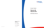
Air Heater Air Top 2000 S B (Gasoline) Air Top 2000 S D (Diesel) Installation Manual – Improper installation or repair of Webasto heating and cooling systems can cause fire or the leakage of deadly carbon monoxide leading to serious injury or death. – Installation and repair of Webasto heating and cooling systems requires special Webasto training, technical information, special tools and special equipment. – NEVER attempt to install or repair a Webasto heating or cooling system unless you have successfully completed the factory training course and have the technical skills, technical information, tools and equipment required to properly complete the necessary procedures. – ALWAYS carefully follow Webasto installation and repair instructions and heed all WARNINGS. – Webasto rejects any liability for problems and damage caused by the system being installed by untrained personnel. Air Top 2000 ST Table of Contents Contents Page 1. Safety and General Information 1.1 1.2 1.3 3 General Information . . . . . . . . . . . . . . . . . . . . . . . . . . . . . . . . . . . . . . . . . . . . . . . . . . . . . . . . . . . . . . . . . . . . . . . . . . 3 Safety Signals . . . . . . . . . . . . . . . . . . . . . . . . . . . . . . . . . . . . . . . . . . . . . . . . . . . . . . . . . . . . . . . . . . . . . . . . . . . . . . . 3 Additional Documentation to be Used . . . . . . . . . . . . . . . . . . . . . . . . . . . . . . . . . . . . . . . . . . . . . . . . . . . . . . . . . . . . 3 2. Regulation for Installation in the Vehicle 2.1 2.2 2.3 2.4 2.5 2.6 2.7 2.8 4 Scope . . . . . . . . . . . . . . . . . . . . . . . . . . . . . . . . . . . . . . . . . . . . . . . . . . . . . . . . . . . . . . . . . . . . . . . . . . . . . . . . . . . . . 4 Position of the Heater . . . . . . . . . . . . . . . . . . . . . . . . . . . . . . . . . . . . . . . . . . . . . . . . . . . . . . . . . . . . . . . . . . . . . . . . . 4 Fuel Supply . . . . . . . . . . . . . . . . . . . . . . . . . . . . . . . . . . . . . . . . . . . . . . . . . . . . . . . . . . . . . . . . . . . . . . . . . . . . . . . . . 4 Exhaust System. . . . . . . . . . . . . . . . . . . . . . . . . . . . . . . . . . . . . . . . . . . . . . . . . . . . . . . . . . . . . . . . . . . . . . . . . . . . . . 4 Combustion Air Inlet. . . . . . . . . . . . . . . . . . . . . . . . . . . . . . . . . . . . . . . . . . . . . . . . . . . . . . . . . . . . . . . . . . . . . . . . . . 4 Hot Air Inlet . . . . . . . . . . . . . . . . . . . . . . . . . . . . . . . . . . . . . . . . . . . . . . . . . . . . . . . . . . . . . . . . . . . . . . . . . . . . . . . . 5 Hot Air Outlet. . . . . . . . . . . . . . . . . . . . . . . . . . . . . . . . . . . . . . . . . . . . . . . . . . . . . . . . . . . . . . . . . . . . . . . . . . . . . . . 5 Automatic Control of the Heating System . . . . . . . . . . . . . . . . . . . . . . . . . . . . . . . . . . . . . . . . . . . . . . . . . . . . . . . . . . 5 3. Purpose of the Air Heater 6 4. Installation 7 4.1 4.2 4.3 4.4 4.5 Recommended Installation and Service Tools. . . . . . . . . . . . . . . . . . . . . . . . . . . . . . . . . . . . . . . . . . . . . . . . . . . . . . . . 7 Air Top 2000 S Installation Situation . . . . . . . . . . . . . . . . . . . . . . . . . . . . . . . . . . . . . . . . . . . . . . . . . . . . . . . . . . . . . . 7 Installation Location . . . . . . . . . . . . . . . . . . . . . . . . . . . . . . . . . . . . . . . . . . . . . . . . . . . . . . . . . . . . . . . . . . . . . . . . . . 7 To Install the Heater . . . . . . . . . . . . . . . . . . . . . . . . . . . . . . . . . . . . . . . . . . . . . . . . . . . . . . . . . . . . . . . . . . . . . . . . . . 8 Optional Mounting Plate. . . . . . . . . . . . . . . . . . . . . . . . . . . . . . . . . . . . . . . . . . . . . . . . . . . . . . . . . . . . . . . . . . . . . . . 9 5. Factory Plate 10 6. Installation Example 11 7. Hot Air System 12 7.1 External Temperature Sensor. . . . . . . . . . . . . . . . . . . . . . . . . . . . . . . . . . . . . . . . . . . . . . . . . . . . . . . . . . . . . . . . . . . 13 7.1.1 To Install the External Temperature Sensor . . . . . . . . . . . . . . . . . . . . . . . . . . . . . . . . . . . . . . . . . . . . . . . . . . . 13 8. Fuel Supply 14 8.1 8.2 8.3 8.4 Vehicles with a Carburetor Equipped Engine . . . . . . . . . . . . . . . . . . . . . . . . . . . . . . . . . . . . . . . . . . . . . . . . . . . . . . . 14 Vehicles with Fuel Injection Engines . . . . . . . . . . . . . . . . . . . . . . . . . . . . . . . . . . . . . . . . . . . . . . . . . . . . . . . . . . . . . 15 Vehicles with Diesel Engines . . . . . . . . . . . . . . . . . . . . . . . . . . . . . . . . . . . . . . . . . . . . . . . . . . . . . . . . . . . . . . . . . . . 15 Fuel Lines . . . . . . . . . . . . . . . . . . . . . . . . . . . . . . . . . . . . . . . . . . . . . . . . . . . . . . . . . . . . . . . . . . . . . . . . . . . . . . . . . 15 8.4.1 Connecting Two Fuel Lines with a Coupler Hose . . . . . . . . . . . . . . . . . . . . . . . . . . . . . . . . . . . . . . . . . . . . . . 16 8.5 Fuel Metering Pump . . . . . . . . . . . . . . . . . . . . . . . . . . . . . . . . . . . . . . . . . . . . . . . . . . . . . . . . . . . . . . . . . . . . . . . . . 16 8.5.1 Installation Location . . . . . . . . . . . . . . . . . . . . . . . . . . . . . . . . . . . . . . . . . . . . . . . . . . . . . . . . . . . . . . . . . . . 16 8.5.2 Installation and Attachment . . . . . . . . . . . . . . . . . . . . . . . . . . . . . . . . . . . . . . . . . . . . . . . . . . . . . . . . . . . . . 17 8.6 Fuel Filter . . . . . . . . . . . . . . . . . . . . . . . . . . . . . . . . . . . . . . . . . . . . . . . . . . . . . . . . . . . . . . . . . . . . . . . . . . . . . . . . . 17 9. Combustion Air Supply 18 10. Exhaust Pipe 19 11. Combustion Air Inlet and Exhaust Lines 20 12. Electrical Connections 21 12.1 Heater Connection . . . . . . . . . . . . . . . . . . . . . . . . . . . . . . . . . . . . . . . . . . . . . . . . . . . . . . . . . . . . . . . . . . . . . . . . . . 21 12.2 Supply Voltage Connection. . . . . . . . . . . . . . . . . . . . . . . . . . . . . . . . . . . . . . . . . . . . . . . . . . . . . . . . . . . . . . . . . . . . 21 12.3 Control Element (Rheostat) Connection . . . . . . . . . . . . . . . . . . . . . . . . . . . . . . . . . . . . . . . . . . . . . . . . . . . . . . . . . . 22 13. Circuit Diagrams 23 13.1 Legend for Circuit Diagrams . . . . . . . . . . . . . . . . . . . . . . . . . . . . . . . . . . . . . . . . . . . . . . . . . . . . . . . . . . . . . . . . . . . 23 www.webasto.us 1 Webasto Product N.A., Inc. Table of Contents Air Top 2000 S 14. Starting the Heater for the First Time 27 14.1 Control Element Description . . . . . . . . . . . . . . . . . . . . . . . . . . . . . . . . . . . . . . . . . . . . . . . . . . . . . . . . . . . . . . . . . . .27 15. Fault Lock-out 28 15.1 Error Code Output . . . . . . . . . . . . . . . . . . . . . . . . . . . . . . . . . . . . . . . . . . . . . . . . . . . . . . . . . . . . . . . . . . . . . . . . . .28 16. Technical Data 29 16.1 Electrical Components: . . . . . . . . . . . . . . . . . . . . . . . . . . . . . . . . . . . . . . . . . . . . . . . . . . . . . . . . . . . . . . . . . . . . . . .29 16.2 Fuel for Air Top 2000 S B (Gasoline): . . . . . . . . . . . . . . . . . . . . . . . . . . . . . . . . . . . . . . . . . . . . . . . . . . . . . . . . . . . . .29 16.3 Fuel for Air Top 2000 S D (Diesel/Heating Oil): . . . . . . . . . . . . . . . . . . . . . . . . . . . . . . . . . . . . . . . . . . . . . . . . . . . . . .29 17. Version 30 18. Drilling Template 31 19. Technical Service Bulletins / Product Information / Updates 32 www.webasto.us 2 Webasto Product N.A., Inc. Air Top 2000 S 1. 1.1 Safety and General Information Safety and General Information General Information Webasto Product North America, Inc. is pleased to provide this installation manual with the Air Top 2000 S heating system. When used according to the guidelines stated in this manual, you can expect to provide years of trouble-free, enjoyable operation for your customer. This manual represents our latest effort to produce the best technical documentation possible. In our efforts towards continuous, ongoing product improvement, we encourage our customers to write to us with their comments or criticisms concerning this manual and the Air Top 2000 S heating system. Please write to us at: Webasto Product North America, Inc. Technical Documentation Group 15083 North Road Fenton MI 48430 You are also invited to fill out our online questionnaire concerning our technical documentation and web site at: www.techwebasto.com If you have any immediate questions concerning this manual, the installation procedures within or the product itself, please call us at: (800) 432-8371 1.2 or send a fax to: (810) 593-6001 Safety Signals The purpose of safety symbols is to attract your attention to possible hazardous conditions. This guide uses a series of symbols and signal words which are intended to convey the level of importance of the safety messages. The progression of symbols is described below. Remember that safety messages by themselves do not eliminate danger and are not a substitute for proper accident prevention measures. DANGER: Indicates that non-compliance with instructions or procedures WILL result in serious injury or death. WARNING: Indicates that non-compliance with instructions or procedures MAY result in serious injury or death. CAUTION: Indicates that non-compliance with instructions or procedures COULD result in damage to the vehicle or equipment. NOTE: Provides information we feel you would like to have. It could have to do with procedures and tips that will help you work more efficiently. 1.3 Additional Documentation to be Used This guide contains all of the information and procedures necessary for the installation of the AT 2000 S Air Heater. The use of additional documentation is normally not necessary. Vehicle specific installation guides (when available) may be used as complementary information if necessary. www.webasto.us 3 Webasto Product N.A., Inc. Regulation for Installation in the Vehicle 2. Air Top 2000 S Regulation for Installation in the Vehicle Read this installation manual in its entirety before installing this equipment. 2.1 Scope 2.1.1 Subject to the provisions of paragraph 2.1.2, internal combustion heaters must be installed in accordance with the requirements contained in this Annex. 2.1.2 In the case of class trailers with heaters for liquid fuel, it is presumed that these vehicles comply with the requirements in this Annex. 2.2 Position of the Heater 2.2.1 Parts of the vehicle body and other components in the immediate vicinity of the heater must be protected against excessive heat and the danger of contamination by fuel or oil. 2.2.2 The internal combustion heater must not pose a fire hazard even when overheated. This requirement is deemed to have been met if care is taken during installation to ensure an adequate distance from all parts, as well as adequate ventilation and if fire-resistant materials or heat shields are used. 2.2.3 For passenger carrying vehicles such as shuttle busses, transit busses, and coaches, the heater must not be installed in the passenger cabin. A device in a sealed cover, which also meets the requirements set out in paragraph 2.2.2, may be used, however. 2.2.4 The model/ Serial plate or a duplicate thereof (duplicate model/ Serial plate) must be fitted in such a way that it is still clearly legible when the heater has been installed in the vehicle. 2.2.5 When positioning the heater, all reasonable precautions must be taken to minimize the risk of personal injury or damage to items in the vehicle. 2.2.6 A clearly visible indicator within the user's field of vision must show when the heater is switched on or off. 2.3 Fuel Supply 2.3.1 The fuel filler neck must not be located in the passenger compartment and must have a tightly fitting cap to prevent any fuel leaks. 2.3.2 The type of fuel and the fuel filler neck must be clearly identified on heaters for liquid fuel, for which the fuel supply is separate from the fuel supply for the vehicle. 2.3.3 A sign must be affixed to the fuel filler neck warning that the heater must be switched off before refuelling. An identical warning must also be included in the manufacturer's operating instructions. 2.4 2.4.1 2.5 Exhaust System The exhaust outlet must be positioned in such a way that exhaust fumes cannot get into the interior of the vehicle through ventilation devices, hot-air inlets or open windows. Combustion Air Inlet 2.5.1 The air for the combustion chamber of the heater must not be extracted from the passenger cabin of the vehicle. 2.5.2 The air inlet must be positioned in such a way that it cannot be obstructed by other objects. Webasto Product N.A., Inc. 4 www.techwebasto.com Air Top 2000 S 2.6 Regulation for Installation in the Vehicle Hot Air Inlet 2.6.1 The supply of heating air must consist of either fresh air or recirculated air and must be taken from a clean area which cannot be contaminated by exhaust fumes from the engine, the internal combustion heater or any other source in the vehicle. 2.6.2 The inlet line must be protected by a grating or other suitable means. 2.7 Hot Air Outlet 2.7.1 Hot air lines within the vehicle must be positioned or protected in such a way as to exclude all risk of injury or damage caused by direct contact. 2.7.2 The air outlet must be positioned or protected so that it cannot be obstructed by other objects. 2.8 Automatic Control of the Heating System When the engine stops, the heating system must cut out automatically and the fuel supply must be stopped within 5 seconds. The heating system may remain in operation if a manual unit has already been activated. NOTE: Failure to follow the installation instructions and the notes contained therein will lead to all liability being refused by Webasto. The same applies if repairs are carried out incorrectly or with the use of parts other than genuine Webasto service parts. This will result in the invalidation of the type approval for the heater and therefore of its homologation / type licence. www.webasto.us 5 Webasto Product N.A., Inc. Purpose of the Air Heater 3. Air Top 2000 S Purpose of the Air Heater The Webasto Air Top 2000 S air heaters are designed – to heat cabins, boats, trucks, minibuses, vans and motor homes – to defrost vehicle windows The air heaters operate independently of the engine and are connected to the fuel tank and the electrical system of the vehicle. They may be used for vehicles with either water or air-cooled engines. They are not designed for heating hazardous substances. Webasto Product N.A., Inc. 6 www.techwebasto.com Air Top 2000 S 4. Installation Installation WARNING: The regulations governing installation, beginning on page 4, must be adhered to. The heater must not be operated without the control unit cover (this will cause the heater to overheat). 4.1 4.2 Recommended Installation and Service Tools • Digital Multi-Meter - Should be a good quality VAO meter. • 1/2 Heavy-Duty, low speed drill with good quality, sharp drill bits and a selection of hole saws. • Mounting/ Drilling Templates. Air Top 2000 S Installation Situation NOTE: Check the installation situation of the relevant vehicle type. 4.3 Installation Location The heater may be fitted both in the interior or on the exterior of the vehicle. If it is installed on the exterior ensure that the heater is fitted in a position where it is protected from splashing water and spray. 311 8 6 130 120 6 >155 121 2 1 7 Ø 22 Ø 22 3 > 20 120 5 29 4 Dimensions in millimeters > 20 6 1. 2. 3. 4. 5. 6. 7. 8. Hot air inlet Hot air outlet Combustion air inlet Exhaust gas outlet > 20 Fuel intake Space required for hot air outlet Space required for removing the heater (service) Cable outlet (either right or left) Figure 1. Dimensions of the Heater The heater must be installed in such a way that no water can ingress into it if the vehicle travels through a water hazard for which that vehicle is licensed. The openings for the combustion air inlet port, the exhaust outlet port and the fuel line must be sealed if the heater is installed in the interior. The seal designed and supplied for this purpose must be used (see Figure 4). The same applies when using the optional mounting plate and closed cell foam gasket (see Figure 5). www.webasto.us 7 Webasto Product N.A., Inc. Installation 4.4 Air Top 2000 S To Install the Heater The M6 nuts must be tightened with a torque of 6 Nm +1 Nm for installing the Air Top 2000 S heater. The installation dimensions and space requirement for service access are shown in the installation drawing (Figure 1). The specified horizontal and axial angles must not be exceeded (Figure 2). Figure 2. Recommended Installation Positions for Diesel Heaters We recommend that gasoline heaters be installed with the exhaust port pointing vertically downwards. A seal (Figure 4) must be fitted between the heater and the vehicle body. This seal must be replaced each time the heater is installed. The support area for the heater foot must be flat. A special tools can be purchased from Webasto to drill the holes and, if necessary, smooth the support area. The seal can compensate for unevenness of max. 1 mm. WARNING: installed. The seal and foam gasket must be replaced any time the heater is removed and re- Ø 26 Ø 26 44 Ø 7.5 12 Ø 7.5 Ø 7.5 18 55 Figure 3. Hole Pattern Figure 4. Seal Webasto Product N.A., Inc. 8 www.techwebasto.com Air Top 2000 S 4.5 Installation Optional Mounting Plate 1 2 3 1. Seal - Heater to vehicle floor or optional mounting plate. 2. Mounting plate - Facilitates installation on corrugated vehicle floors. 3. Closed Cell Foam Gasket - Seals area between mounting plate and vehicle floor. WARNING: The seal or foam gasket or both must be replaced each time the heater is removed and reinstalled. A mounting plate template is provided in the installation kit for locating the heater on the floor of the vehicle. All recommended hole locations and sizes are included. Figure 5. Mounting with optional mounting plate CAUTION: When using the optional mounting plate and closed cell foam gasket, do not over tighten the mounting bolts. Doing so will cause the mounting plate to warp and result in stress damage to the heater and fan motor. CAUTION: After installation, check that the heater casing is not in contact with any parts of the vehicle body. A failure to do this may result in the hot air fan binding internally (Figure 6). Ensure that all moving part can move freely Figure 6. Installation www.webasto.us 9 Webasto Product N.A., Inc. Factory Plate 5. Air Top 2000 S Factory Plate The model/serial number plate of the heater must be positioned so that it cannot be damaged and must be clearly legible when the heater is installed (otherwise a duplicate model plate must be used). Inapplicable years must be erased from the model plate. Webasto Product N.A., Inc. 10 www.techwebasto.com Air Top 2000 S Installation Example 7 1 6 2 3 4 5 1 2 3 4 5 6 7 Control Element AT 2000 S Heater Fuel Metering Pump Fuel Filter (Optional) Fuel Satndpipe Exhaust Muffler (Optional) Fuse Block 6. Installation Example Figure 7. Installation example with heater in stalled under-bunk. (Recirculation mode) www.webasto.us 11 Webasto Product N.A., Inc. Hot Air System 7. Air Top 2000 S Hot Air System NOTE: The heater must not be integrated into the vehicle’s air system. Both recirculation and fresh air modes are possible. For fresh air mode it must be ensured that the hot air is taken from an area protected from splashing water and spray and in such a way that no water can ingress into the heater if the vehicle travels through a water hazard for which that vehicle is licensed. NOTE: For fresh air mode, an external temperature sensor must be fitted in the appropriate zone. Inside the control unit there is a temperature sensor, which operates the heater in the appropriate heat output range in conjunction with the control element depending on the intake temperatures and the position of the set point generator. The heat output is controlled such that after the selected interior temperature has been reached quickly, it is then kept at this selected value. The internal diameter of the main section of the hot air line should be 60 mm (2.36 in.) minimum. CAUTION: Only materials that can permanently withstand temperatures of at least 130°C (266°F) may be used for the hot air line. The hot air opening is to be positioned in such a way that the air is not blown on to any parts that cannot withstand the heat. CAUTION: In vehicles used to transport people, the air outlet opening is to be directed in such a way that it is at least 20 cm (8 in.) away from all body parts. Maximum pressure drop between the inlet and outlet side of the hot air line: Air Top 2000 S 1.0 hPa 1 hPa corresponds to 1 mbar corresponds to 10 mm Water Column (0.4 inches Water Column). If this value is exceeded the temperature limiter will trip. The hot air hose must be secured at its connection points. If the heater is used in air recirculation mode, it must be used without any accessories for controlling the hot air (a short circuit of the hot air flow must be avoided). The hot air hose must be secured at its connection points. If the heater is used in recirculation mode, for example, in the under bunk compartment of a truck’s sleeper, without a hot air directional outlet grille, do not short circuit the hot air flow. Figure 8. Hot air inlet and hot air outlet (recirculation mode) CAUTION: If you use the heater without a hot air inlet hose, the inlet grille supplied with the heater must be used at all times. Webasto Product N.A., Inc. 12 www.techwebasto.com Air Top 2000 S Hot Air System NOTE: The installation must be checked for: –Air short circuit between the vehicle’s heating system and the heater air inlet. –Air short circuit between the heater’s air inlet and the heater’s air outlet (Figure 8). Figure 9. Hot air inlet with inlet grille If you use an installation box the air vent must be sealed in such a way that no hot air can get into the installation box. 7.1 External Temperature Sensor The installation of an external temperature sensor is recommended if the heater is operated in fresh air mode. 7.1.1 To Install the External Temperature Sensor The external temperature sensor must be installed at medium height in the passenger cabin on vertical surfaces if possible in the area that requires heating. The temperature sensor must not – be in the direct current of hot air (from the vehicle’s own heating system or the hot air heater). – by close to heat sources (for example the vehicle’s own heating system). – be placed in direct sunlight (for example on the dashboard). – be installed behind curtains or the like. Figure 10. External temperature sensor - optional www.webasto.us 13 Webasto Product N.A., Inc. Fuel Supply 8. Air Top 2000 S Fuel Supply The fuel is taken from the vehicle fuel tank or from a separate fuel tank. The values for the maximum pressure at the fuel extraction point are shown in Figure 11. Permissible fuel inflow height H At max. pressure in fuel line 0.00 m (0.00 in.) 0.2 bar (2.9 PSI) 1.00 m (39.4 in.) 0.11 bar (1.6 PSI) 2.00 m (78.7 in.) 0.03 bar (0.44 PSI) Maximum fuel intake height S At max. negative pressure in the fuel tank 0.00 m (0.00 in.) -0.10 bar (-1.45 PSI) 0.50 m (19.7 in.) -0.06 bar (-0.87 PSI) 1.00 m (39.4 in.) -0.02 bar (-0.29 PSI) max.3m I2 iØ2mm iØ2mm I1 A sign must be affixed to the fuel tank’s filler neck warning that the heater must be switched off before refuelling. I 1 + I 2 10 m I 1 1.2 m I 2 8.8 m iØ2mm iØ2mm I2 H S I1 Figure 11. Fuel supply 8.1 Vehicles with a Carburetor Equipped Engine The fuel may only be extracted using the special Webasto fuel extractor (see Figure 12) as close to the tank as possible. The connection may be made in either the supply or return line, in which case the return line must lead almost to the base of the tank (see Figure 13). The fuel extractor must be fitted in such a way that any air or gas bubbles are automatically discharged towards the tank (see Figure 12). 0-60° a= 6 Ø 8Ø Ø 5 10 Ø 12 Ø 0-60° 0-60° 0-60° 0-60° 0-60° From Tank To Engine To Fuel Metering Pump Figure 12. Webasto fuel extractor The fuel extractor should not be located near the engine, as gas bubbles may form in the lines on account of heat radiated from the engine. This may cause problems during combustion. Webasto Product N.A., Inc. 14 www.techwebasto.com Air Top 2000 S 8.2 Fuel Supply Vehicles with Fuel Injection Engines When installing the heater in a vehicle with fuel injection system, it is important to establish whether the fuel pump is located inside or outside the tank. If the fuel pump is located inside the tank, fuel can only be extracted from the return line using the Webasto fuel extractor (see Figure 12), in which case it must be ensured that the return line continues almost to the bottom of the tank (see Figure 13 for details of the minimum distance from the bottom of the tank). If this is not the case Webasto fuel extractors or standpipes (see Figures 13, 14 and 15) may be used. If the fuel pump is installed outside the tank, the fuel connection may also be made between the tank and the fuel pump, again using only the Webasto fuel extractor (see Figure 12). 8.3 Vehicles with Diesel Engines The fuel must be taken from the vehicle fuel tank or from a separate tank (see Figs. 13, 14 and 15). This separate fuel pickup precludes any effect of pressure. Hole pattern 25 Only use this Standpipe on fuel * tanks constructed from metal Minimum distance 25 mm (1 in.) Figure 13. Webasto fuel standpipe CAUTION: The tank fitting must be made from metal! 8.4 Fuel Lines Only steel, copper and plastic lines of plasticized, light and temperature-stabilized PA 11 or PA 12 (e.g. Mecanyl RWTL) pursuant to DIN 73378 may be used for the fuel lines. Since the lines normally cannot be routed with a constant rising gradient, the internal diameter must not be allowed to exceed a certain size. Air or gas bubbles will accumulate in lines with an internal diameter of more than 4 mm (5/32 in.) and these will cause malfunctions whilst the heater is operating if the lines sag or are routed downwards. The diameters specified in Figure 11 will ensure that bubbles do not form. The lines should not be routed downwards from the metering pump to the heater. Unsupported fuel lines must be secured to prevent them from sagging. They must be installed in such a way that they cannot be damaged by flying road debris and high temperatures (exhaust line). The fuel lines must be secure at the connections using hose clamps to prevent their slipping. www.webasto.us 15 Webasto Product N.A., Inc. Fuel Supply Air Top 2000 S Tank Connector Sealing ring Plastic tank Tank Fitting Sealing ring Figure 14. Fuel supply from plastic tank drain screw 8.4.1 Figure 15. Fuel supply from plastic tank fitting Connecting Two Fuel Lines with a Coupler Hose The correct procedure for connecting fuel lines with hosing is shown in Figure 16. Ensure that there are no leaks. Correct Clamp Wrong Bubble Bubble Figure 16. Fuel line / coupler hose connection 8.5 Fuel Metering Pump The fuel metering pump is a combined delivery, metering and shut-off system and is subject to certain installation criteria (see Figures 11 and 17). 8.5.1 Air Top 2000 ST 12 V and 24 V – Diesel only (with damper) Installation Location It is advisable to install the metering pump in a cool place. The maximum ambient temperature must not exceed +20 °C (68 °F) for gasoline heaters at any time during operation. The metering pump and fuel lines must not be installed within range of the radiated heat from hot vehicle parts. A heat shield must be used if necessary . Webasto Product N.A., Inc. 0-180° 0-180° Figure 17. Fuel metering pump DP 30.2 / 30.3 16 www.techwebasto.com Air Top 2000 S 8.5.2 Fuel Supply Installation and Attachment The metering pump must be secured with a vibration-damping mounting. Its installation position is limited as shown in Figure 17 in order to ensure effective automatic bleeding. As a result of the risk of corrosion, only genuine Webasto parts may be used for the plug connections between the metering pump and the metering pump wiring harness. 8.6 Fuel Filter Only a Webasto filter is allowed to be used if the fuel is expected to be contaminated. Install vertically if possible, however at least horizontally (check flow direction). CAUTION: Do not substitute the Webasto supplied fuel filter with a non Webasto replacement. Irregular heater operation may result. 0° - 90° A Ø5 Figure 18. Fuel filter www.webasto.us 17 Webasto Product N.A., Inc. Combustion Air Supply 9. Air Top 2000 S Combustion Air Supply Under no circumstances may the combustion air be taken from areas occupied by people. The combustion air intake opening must not point in the direction of travel. It must be located so that it cannot become clogged with dirt and road debris. NOTE: An intake silencer must be fitted if the intake hose length is greater than 0.6 m (24 in.). NOTE: The combustion air must be extracted using a combustion air line from a position that is as cool as possible and protected from splashing water. CAUTION: Do not use an exhaust line as the combustion air line since otherwise the metering pump cable from the combustion air inlet port may be damaged. The combustion air opening must not be under the minimum water drive-through level permitted for the vehicle. See the regulations for the installation for further regulations. Webasto Product N.A., Inc. 18 www.techwebasto.com Air Top 2000 S Exhaust Pipe 10. Exhaust Pipe Rigid pipes of unalloyed or alloyed steel with a minimum wall thickness of 1.0 mm (3/64 in.) or flexible piping of alloyed steel only must be used as exhaust line. The exhaust pipe is secured to the heater using a clamping collar, for example. See the ‘regulations for installation’ for other requirements. The exhaust muffler should ideally be installed near the heater. The heater may also be operated without a muffler. Ø 6.5 0-90° 0-90° Figure 19. Exhaust muffler - exhaust flow is non-directional (arbitrary) www.webasto.us 19 Webasto Product N.A., Inc. Combustion Air Inlet and Exhaust Lines Air Top 2000 S 11. Combustion Air Inlet and Exhaust Lines Both lines are to be installed falling away from the heater. If this is not possible, a condensate drain hole with a diameter of 4 mm (5/32 in.) must be made at its lowest point. Figure 20. Prevent the formation of condensate The lines must not point to the front of the vehicle. Figure 21. Lines must not point in the direction of travel The lines must be located so that they cannot become clogged with dirt and road debris. Figure 22. Avoid the lines becoming clogged with dirt Length of the combustion air inlet and exhaust lines in total: With muffler: max. 2.0 m Without muffler: max. 5.0 m The exhaust pipe must be securely attached no further than 150 mm (6 in.) from the end of the exhaust pipe to ensure that the angle of 90° ± 10° is maintained. If the exhaust line is over 2 m in length, the lines must be insulated (to prevent falling below the dewpoint). Internal diameter of the lines: Combustion air line: exhaust line (metal): 22 mm 22 mm Minimum bending radius: 50 mm Installation position 10° Total bends: Combustion air line: Exhaust line: 10° max. 270° max. 270°. Discharge direction almost vertical 90° ± 10° CAUTION: If the exhaust pipe ends other than as shown in Figure 23, it will pose a fire risk. Webasto Product N.A., Inc. 20 Figure 23. Exhaust pipe opening www.techwebasto.com Air Top 2000 S Electrical Connections 12. Electrical Connections All the cables and wires that are not required must be insulated against accidental shorting or grounding. NOTE: The electrical connection is made as shown in the system circuit diagram (Figure 31). 12.1 Heater Connection To connect the wiring harness, remove the control unit cover on the heater and connect the wiring harness plug to the control unit. Figure 24. To remove the control unit cover NOTE: Raise the control unit cover on both sides using a blunt blade (Figure 24 arrows). Before using the heater for the first time, fit the control unit cover in place on the heater to prevent the escape of hot air (heater overheating). The cable passage of the cover can be placed at either the left or right side. To ensure that the cable passage in the control unit cover seals perfectly, the cable grommet is to be adjusted appropriately on the wiring harness. 12.2 Supply Voltage Connection Ideally from the vehicle’s central electrical system or at the batteries. A weather sealed fuse holder is to be fitted to protect the heater (supplied with the heater harness). F = 20A (12V) F = 15A (24V) Figure 25. Fuse holder - weather sealed CAUTION: The Air Top 2000 S requires 75 watts at 12 or 24 volts during start-up. The main power connection has to be made at a circuit designed to sustain this load without voltage drop. Cigar lighter sockets and auxiliary power outputs for C.B. radio’s and other electronic accessories are not considered adequate power supplies for the Air Top 2000 S. www.webasto.us 21 Webasto Product N.A., Inc. Electrical Connections Air Top 2000 S 12.3 Control Element (Rheostat) Connection The wiring harness is prepared for connection to the control element. Simply pull on the connector housing to unplug the connector. Shaft requires a 12 mm (15/32 in.) hole to mount. The connector housing can be locked (self-locking action) by simply pulling on the wiring harness. Locate the control element in a convenient location. The control element is not affected by temperature. Temperature is monitored inside the heater or via an optional external temperature sensor (see Figure 29). Figure 26. Control element (rheostat) NOTE: The fibre optic lens must be in contact with the rotary knob. Figure 27. Installation of the control element - correct NOTE: The rotary knob must sit flush with the bezel (Figure 27) not above it as illustrated in Figure 28. Figure 28. Installation of the control element - incorrect NOTE: As an option an external temperature sensor may be installed in the passenger cabin (see page13). See installation instructions included with the sensor or see the service instructions in the Workshop manual for further information. Figure 29. External temperature sensor - optional Webasto Product N.A., Inc. 22 www.techwebasto.com Air Top 2000 S Circuit Diagrams 13. Circuit Diagrams 13.1 Legend for Circuit Diagrams c With positive from terminal (15/75) to connection 10: Permanent operation for immediate heat as long as the ignition is switched on Without positive at connection 10: Heating time is variably programmable (10 min to 120 min), default setting 120 min Item Description Comment A1 A2 B1 B2 B3 E F1 H1 H7 Air Top 2000 S Heater Control module Flame sensor Temperature sensor Overheating sensor Ceramic glow pin Fuse 24 V 10 A/12 V 15 A LED, green (in item S1) LED red (in item P) H8 Heating symbol in the display (in item P) H9 Light (in item P) M Motor P1 Combination timer (1531) S1 Control element X1-X5 Plug connector, 2-pin X6 Plug connector, 8-pin X7 Plug connector, 4-pin X8 Plug connector, 2-pin X9 Plug connector, 2-pin X11 Plug connector, 6-pin X12 1-pin Plug connection X13 12-pin Plug connection Y1 Dosing pump Cable colors (where applicable) bl br ge gn gr or rt sw vi ws blue brown yellow green grey orange red black violet white Combination Timer 1531 Grey Lights (1) (optional) Internal Overheating guard Flat fuse SAE J 1284 Indicator Light in immediate heat button, ready indicator, ON indicator On indicator, overheating indicator Display light Combustion and hot air fan Set point generator switch To item A2 To item A2 To item S1 To item Y1 To item A2 To item A2 PC Diagnostic Link To item P1 Black Battery Positive or Ignition Signal (10) Red Battery Positive (11) 12V 24V Brown Battery Negative (12, 4) 1 2 3 4 5 7 6 8 0 9 11 1 12 Adapter Harness P/N 9008440A Figure 30. Air Top 2000 S with combination timer 1531 - connection diagram www.webasto.us 23 Webasto Product N.A., Inc. 31 58 S1 H1 2 1 4 3 X7 0,5mm² ws 0,5mm² bl 8 5 3 7 1 X6 0,5mm² sw 0,5mm² rt br 15 A1 vi/ws M X1 1 rt 2 vi ge 2 E X4 1 F2 2 ge B1 X3 2 - 1 br B2 X9 2 - 1 6 X2 1 4 Y1 sw br 24 sw Webasto Product N.A., Inc. bl 30 2 X8 bl - X5 1 B3 2 bl A2 1 4 6 5 31 2 0,5mm² gn/ws 3 0,5mm² vi 0,5mm² gr X11 2 1 X12 X8 X7 3 6 4 E 5 2 4 3 8 2 1 1 X9 2 4 6 7 X11 X6 X5 X4 X3 X2 X1 B1 B3 13 5 X6 2 1 1 A2 B 2 A2 X1,2,3,4,5 X9 X11 X12 58 (75) 15 30 Circuit Diagrams Air Top 2000 S Figure 31. Standard system wiring diagram for the Air Top 2000 S, 12 / 24 Volt with control element. www.techwebasto.com 31 P1 H9 12 1 1,0 mm² 58 10 1 7 4 S3 H8 H7 11 9 6 8 2 X13 1 3 X6 8 0,5mm² ws 5 0,5mm² bl 0,5mm² sw 7 0,5mm² rt 1,0 mm² br 15 A1 vi/ws M M E 1 2 2 vi ge ge X4 X1 1 rt 2 F2 B1 1 X3 br br 2 B2 X9 2 - 1 6 X2 1 4 Y1 sw br 25 sw www.webasto.us bl 30 2 X8 - B3 2 bl X5 bl 1 A2 0,5mm² vi 0,5mm² gr 1 4 6 5 2 0,5mm² gn/ws 3 X11 58 15 30 X12 X9 X11 A2 A2 3 6 9 X12 X8 E 12 6 2 1 X6 X1,2,3,4,5 B2 5 2 4 3 8 7 1 X13 2 1 X9 2 4 6 13 5 X11 X6 X5 X4 X3 X2 X1 B1 B3 Air Top 2000 S Circuit Diagrams Figure 32. Standard system wiring diagram for the Air Top 2000 S, 12 / 24 Volt with combination timer 1531. Webasto Product N.A., Inc. 31 P2 H9 12 10 1 S3 7 H8 4 S1 H7 11 9 6 8 2 X13 0,5mm² bl 2 1 4 3 X7 1 X6 8 5 3 0,5mm² sw 7 0,5mm² rt 1,0 mm² 0,5mm² ws 1 1,0 mm² 58 br 15 A1 vi/ws M M E 1 2 2 vi ge X4 ge X1 1 rt 2 F2 B1 1 br X3 br 2 B2 X9 2 - 1 6 X2 1 4 Y1 sw br 26 sw Webasto Product N.A., Inc. bl 30 2 X8 - B3 2 bl X5 bl 1 A2 0,5mm² vi 0,5mm² gr 1 4 6 5 2 0,5mm² gn/ws 3 X11 58 15 30 X12 2 1 3 6 9 X12 X8 X7 12 3 6 4 2 1 E 4 3 8 7 1 X13 2 1 X11 X6 X5 X4 X3 X2 X1 B1 B3 X9 2 4 6 13 5 X6 2 5 A2 A2 X1,2,3,4,5 X9 X11 B2 Circuit Diagrams Air Top 2000 S Figure 33. Standard system wiring diagram for the Air Top 2000 S, 12 / 24 Volt with combination timer 1531 and control element. www.techwebasto.com Air Top 2000 S Starting the Heater for the First Time 14. Starting the Heater for the First Time After you have installed the heater, bleed the fuel supply system carefully. NOTE: As a result of the low fuel consumption the heater must be switched on several times to fill the fuel line and prime the system. Conduct a trial of the heater to check all the connections for leaks and to ensure that they are secure. If the heater suffers a fault during operation, the fault must be located and remedied. 14.1 Control Element Description Control Element Rotary knob for: - Switching on and off - Setting the room temperature - Resetting after a fault cut-out Indicator / Error code display ! Changes to the settings on the control element are implemented after a delay. Figure 34. Control element www.webasto.us 27 Webasto Product N.A., Inc. Fault Lock-out Air Top 2000 S 15. Fault Lock-out The control unit continuously monitors the heater operation. The control unit identifies errors on individual heater components and faults during operation. Should the control unit experience component errors and operational faults, the heater will be shut down. The heater is shut down (fault lock-out) if: – No or incorrect start – Flame monitor resistance incorrect – Temperature sensor resistance too low – Ceramic glow pin / actuation incorrect – Fan motor overload or blocked or short circuit or interrupt – Error in the fuel metering pump or overheating guard circuit (start phase only) – Under voltage less than 10 V or over voltage greater than 15 V and for longer than 20 seconds (on 12 V heater) – Under voltage less than 20 V or over voltage greater than 30 V and for longer than 20 seconds (on 24 V heater) – Control unit defective The fuel supply is stopped if the heater overheats. The heater continues to run in the same way as if it is switched off manually. After the heater stops the control unit will be set to fault lock-out. Overheating is indicated by the indicator flashing. Rectify the cause of the fault. To reset the fault, switch the heater On and Off briefly (at least 2 seconds) and then On again. 15.1 Error Code Output NOTE: An error code is generated on the control element indicator light after an error has occurred. When determining the generated code, there will be a series of 5 fast flashes after which, the error code will be generated by a sequence of long flash pulses, count only the long flash pulses to obtain the code. Error codes are shown in the table below. If the heater is fitted with a combination timer, an error message will appear on the display of the timer after a fault occurs. If the control element is used, the error number is indicated by the indicator light flashing: F 00 F 01 F 02 F 03 F 04 F 05 F 06 F 07 F 08 F 09 F 10 Control unit error / incorrect data set No start (after 2 attempts to start) / no flame formation Flame failure (repeated more than 5 times) Under voltage or over voltage Premature flame recognition Flame monitor interrupt or short circuit Temperature sensor interrupt or short circuit Metering pump interrupt or pump short circuit Fan motor interrupt or short circuit or overload or blocked Ceramic glow pin interrupt or short circuit Overheating Webasto Product N.A., Inc. 28 www.techwebasto.com Air Top 2000 S Technical Data 16. Technical Data Except where limit values are specified, the technical data refer to the usual heater tolerances of ±10% at an ambient temperature of +20 °C (68 °F) and at the rated voltage and in rated conditions. 16.1 Electrical Components: Control unit, motor, metering pump, lamp in the timer and ceramic glow pin are designed for either 12 V or 24 V. The timer, flame sensor and temperature limiter component are not dependent on voltage. 16.2 Fuel for Air Top 2000 S B (Gasoline): The fuel specified by the vehicle manufacturer must be used. 16.3 Fuel for Air Top 2000 S D (Diesel/Heating Oil): The diesel fuel specified by the vehicle manufacturer must be used. Heating oil may also be used as long as it complies to the normal quality available on the North American market. We know of no negative influences due to additives. If fuel is extracted from the vehicle’s tank, follow the additive instructions issued by the vehicle manufacturer. If you change to low-temperature fuel, the heater must be operated for approx. 15 minutes so that the fuel system is filled with the new fuel. The Air Top 2000 S heater is also licensed for use with PME (bio-diesel), which complies with DIN EN 14214. Heater Operation Type test permit EMC Heater Air Top 2000 S B e1*72/245*95/54*1085*-e1*2001/56*0014*-- Model Air heater with evaporator burner Heat output Control range 1.0 - 2.0 kW (3753 - 7000 Btu) 0.9 - 2.0 kW (3070 - 7000 Btu) Gasoline Diesel/PME 0.1 .. 0.2 kg/h (0.14 .. 0.27 l/h) 0.1 .. 0.21 kg/h (0.12 .. 0.24 l/h) Fuel Fuel consumption Control range Rated voltage Operating voltage range Rated power consumption Max. ambient temperature: Heater: Metering pump Control element 12 V 12 / 24 V 10 - 15 V 10 - 15 /20 - 30 Volt Control range 9 - 22 W -40... +40 °C (-40... +104 °F) -40... +85 °C (-40... +185 °F) -40... +20 °C (-40... +68 °F) -40... +85 °C (-40... +185 °F) -40... +75 °C (-40... +167 °F) -40... +85 °C (-40... +1854 °F) - Operation - Storage - Operation - Storage - Operation - Storage Maximum combustion air inlet temperature -40... +20 °C (-40... +68 °F) Adjustment range for interior temperature Control range Delivery rate for hot air Against 0.5 bar CO2 in the exhaust fumes (normal function range) Max. +10... +45 °C (+50... +113 °F) max. 70 m3/h (41.2 cfm) 9.5 ... 10.5 Heater dimensions 9.5 ... 12.0 Length 311 ± 2 mm (12.24 ± 0.08 in.) Width 120 ± 1 mm (4.72 ± 0.04 in.) Height 121 ± 1 mm (4.76 ± 0.04 in.) Weight www.webasto.us Air Top 2000 S D 2.6 kg (5.73 lb) 29 Webasto Product N.A., Inc. Version Air Top 2000 S 17. Version Air Top 2000 S B (Gasoline) Air heater for gasoline (12 V) Air Top 2000 S D (Diesel) Air heater for Diesel/heating oil (12 or 24 V) Webasto Product N.A., Inc. 30 www.techwebasto.com Air Top 2000 S Drilling Template 18. Drilling Template Ø 26 Ø 26 44 Ø 7.5 12 Ø 7.5 Ø 7.5 18 55 Figure 35. Drilling Template (Dimensions in millimeters) www.webasto.us 31 Webasto Product N.A., Inc. Technical Service Bulletins / Product Information / Updates Air Top 2000 S Technical Service Bulletin 19. Technical Service Bulletins / Product Information / Updates Category: Thermosystems Document Number: TSB002KS Date Posted: 09/23/2005 Description: Important Information Regarding The Use Of Bio-diesel In Evaporator Burner Heaters Use Of Bio-diesel Fuels: Dear Consumer: Bio-diesel (B20 Soy Based only) can be used in AT 2000, AT 2000S, AT 2000ST, AT 3500, AT 3500ST, AT 5000, AT 5000ST, DBW Series, Thermo 50, Thermo 90, Thermo 90S, Thermo 90ST, and Thermo 230/300 evaporator burner / nozzle style heaters. If this fuel is used we recommend the burner be added as a maintenance item for replacement each year. The reason for the annual replacement of the burner is that bio-diesel causes pre-mature wear. This is not a warranty repair and should not be treated as such. If bio-diesel is used we also recommend that the heater be run for a minimum of 20 minutes every two (2) weeks during the off season. This will help prevent failure of the fuel pump (sticking of the solenoid plunger). There is no warranty for damage caused by poor quality or non approved mixtures of biodiesel or for failure caused by NOT following these recommendations.) can be used in AT 2000, AT 2000S, AT 2000ST, A If you have any questions, contact our technical support team at (800) 432-8371 or via email at [email protected] Webasto Product N.A., Inc. • 15083 North Road • Fenton, Michigan 48430 For Technical Assistance in USA Call: (800) 432-8371 • In Canada Call: (800) 667-8900 Visit us on the Web at: www.techwebasto.com (North America) www.webasto.com (Global) Webasto Product N.A., Inc. 32 Page 1 of 1 www.techwebasto.com Webasto Product N.A., Inc. 15083 North Road Fenton, MI 48430 Technical Assistance Hotline USA: (800) 432-8371 Canada: (800) 667-8900 Org. 11/2007 Rev. N/A P/N AT2S-Install www.webasto.us www.techwebasto.com