1
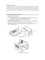
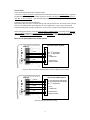
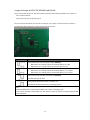
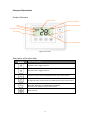
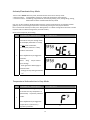
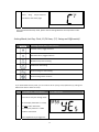
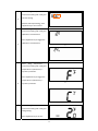
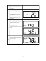
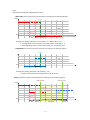
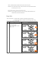
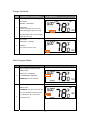
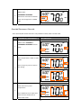
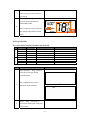
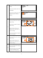
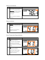
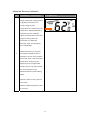
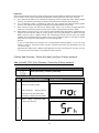
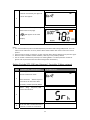
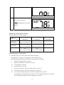
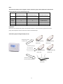
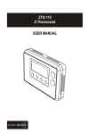
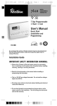
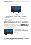
ZTS-110
(Z-Thermostat)
1
Table of Contents
Introduction ............................................................................3
Features List ..........................................................................4
Glossary...................................................................................5
Physical Installation and Wiring .............................................6
Installation Location ............................................................ 7
Physically Installing the Thermostat ...................................... 7
Wiring ............................................................................... 8
Jumper Settings for ELECTH-HPUMP and HE-HG ...................... 10
Setup and Operations .............................................................11
Product Overview .............................................................. 11
Description of Function Keys ................................................. 11
Activate/Deactivate Easy Mode ............................................ 12
Temperature Scale selection in Easy Mode .............................. 12
Setting Mode ...................................................................... 13
Change Mode ..................................................................... 18
Change Fan Mode ............................................................... 19
Select Program Mode .......................................................... 19
Override/Permanent Override ............................................... 20
Setting Schedule ................................................................ 21
Battery Low Indication ......................................................... 24
Defrost Indication ............................................................... 24
Out of Temperature Range Indication .................................... 24
Advanced Recovery Indication .............................................. 25
Filter Counter ..................................................................... 26
Short Cycle Start Up Protection ............................................. 27
Energy Saving Mode ............................................................. 27
Z-Wave Setup and Operations ................................................27
Z-Wave Add (Include) / Delete (Exclude) Mode ....................... 28
Support for Association Groups ............................................. 30
Z-Wave Configuration Parameters ......................................... 32
Reset ZTS-110 to Factory Default Settings .............................35
Frequently Asked Questions ...................................................36
Technical Specifications .........................................................37
Checking Accessories ............................................................38
FCC Notice ..............................................................................38
Warnings ................................................................................38
Caution ...................................................................................38
Warranty ................................................................................39
2
ZTS-110 Z-Thermostat
Introduction ZTS‐110 Z‐Thermostat (Figure 1) is a Z‐Wave enabled programmable thermostat that allows you to control your room temperature with programmable time schedule such as WAKE, AWAY, HOME and SLEEP event which can maximize energy conservation and comfort while minimizing the effort required to maintaining the appropriate temperature in your home whether you are at home or away. Also, you can use the ZTS‐110 to control / check your room temperature by smart phone or PC while you are at home or outside through Z‐Wave gateway. Figure 1. ZTS‐110 3
Features List HVAC System Type Compatible: z
Standard (gas/electric) or Heat Pump Multistage System Compatible: z
z
Standard HVAC Systems: 2 stages heating, 1 stage cooling Heat Pump Systems: 2 stages heating, 1 stage cooling Heat Pump change over valve: z
Program Style: z
z
z
z
z
z
2 program modes for scheduling (Mo‐Fr, Sa‐Su) 4 Separate Time and Temperature Settings for each program Heat and Cool set‐points for each program Temporary Program Override Permanent Program Override Built‐in flash memory stores heat and cool program settings Temperature Display and Control: z
z
z
z
z
z
z
Selectable change over with cool or with heat Temperature display in °F or °C Temperature Measurable Range: 32 – 99 °F / 0 – 40 °C Temperature Setting Range: 41‐99 °F / 5‐37 °C Adjustable Temperature Control Swing/Differential a) Swing: 1°F, 2°F, 3°F or 4°F ( 0.5°C, 1.0°C, 1.5°C or 2°C) b) Differential: 1°F, 2°F, 3°F or 4°F ( 0.5°C, 1.0°C, 1.5°C or 2°C) Advanced Recovery Mode (ARM) Defrost Function Short cycle start up protection Clock: z
Time display format: 12/24 hour clock selection with day displayed Filter Counter: z
Filter change reminder displayed after 500 hours usage (500‐4000hrs) Z‐Wave: z
z
z
z
z
Support Network Wide Inclusion (NWI) and Explore Frames Support Easy mode (disable local advanced setup and control) Support “Frequently Listening Routing Slaves” (FLiRS) mode and “Always Listening” mode Support battery level report Support Association Groups a) Association Group_1 is used for Heat Pump control b) Association Group_2 is used for Compressor control c) Association Group_3 is used to report status change such as AUTO report to gateway Power: z
Support AA x 4 alkaline batteries or 24Vac input 4
Glossary Devices and nodes are all terms to describe an individual Z‐Wave Device or Node device. These are all interchangeable when setting up your Z‐Wave network. Inclusion Add a Z‐Wave device to the network. Exclusion Delete a Z‐Wave device from the network. Remove To take a device out of a group, scene or association group while that device still exists in the same Z‐Wave network. Network Wide Inclusion Network Wide Inclusion (NWI) enables both end‐user friendly, Plug (NWI)
and Play like Z‐Wave network installation as well as professional installation scenario where the inclusion process in terms of time will be reduced significantly. NWI is a feature supported by a new frame type named Explorer which enables the Z‐Wave protocol to implement Adaptive Source Routing.
A collection of Z‐Wave devices is controlled by primary and Z‐Wave Network secondary controllers operating on the same system. A Z‐Wave network has its own unique ID code so that controllers not in the network cannot control the system. The first controller is used to set up your devices and network. Only the Primary Controller can be used to include or delete Primary Controller devices from a network. It is recommended that you mark the primary controller for each network for ease in modifying your FLiRS Mode network. FLiRS is abbreviation for “Frequently Listening Routing Slave”. FLiRS mode is targeted for battery operated applications and will enter sleep mode frequently in order to conserve battery consumption. The response to Z‐Wave command is not as quick as Always Listening Device. Normally there is 1‐2 seconds latency. Always Listening mode is targeted for AC power operated applications and it can act as a repeater, which will re‐transmit the Always Listening Mode RF signal to ensure that the signal is received by its intended destination by routing the signal around obstacle and radio dead spots. The response to Z‐Wave command is immediate. Association is used to organize nodes in different groups allowing Association the device to identify the nodes by a group identifier. The groups can also be copied to other devices. 5
Physical Installation and Wiring L CAUTION − We highly recommend that this installation procedure is performed by a trained HVAC technician. − Read the enclosed instructions carefully before installing your new Z‐Thermostat. Pay close attention to all warnings and notes and carefully follow the installation steps in the order they are presented to save time and minimize the risk of damaging the thermostat or the system it controls. − Turn off ZTS‐110 and the electronic devices (e.g. heater, cooler) which will be connected and the electric source before installation and maintenance. Battery safety! − Use new batteries of the recommended type and size only. − Never mix used and new batteries together. − To avoid chemical leaks, remove batteries from the ZTS‐110 if you do not intend to use the unit for an extended period of time. − Dispose of used batteries properly; do not burn or bury them. Read following scenarios carefully before you start as it matters to the battery life under Z‐Wave operation: ZTS‐110 can be powered by 4 x AA batteries, and/or 24Vac C wire. a) If it is powered by batteries or powered by batteries first then applied with 24Vac before Z‐Wave inclusion, ZTS‐110 will self‐configure to FLiRS mode which will save battery life by sleeping. b) If it is powered by 24Vac or powered by 24Vac first then applied with batteries before Z‐Wave inclusion, ZTS‐110 will self‐configure to Always Listening Mode which will not sleep. c) After inclusion process, ZTS‐110 will not detect power source and not allow changing operation mode. You must perform exclusion process first if need to change Z‐Wave operation mode. d) After Z‐Wave inclusion process, if you reset ZTS‐110 to default while both 24Vac and batteries are applied, ZTS‐110 will take 24Vac as primary power source and self‐configure to Always Listening Mode, because reset to default process will automatically exclude ZTS‐110 from the Z‐Wave network. You should disconnect the power source and re‐apply the power so ZTS‐110 can detect the power source type and self‐configure to corresponding mode. You may check Glossary for the definition of FLiRS mode and Always Listening Mode. 6
Installation Location: The Thermostat is restricted to be used in indoor only. It should be mounted on an inner wall about 1.5m (5ft) above the floor at a position where it is readily affected by changes of the general room temperature with freely circulating air. Avoid mounting above or near hot surfaces or equipment (e.g. TV, heater, refrigerator). Avoid mounting where it will be exposed to direct sunshine, drafts, or in a laundry room or other enclosed space. Do not expose this unit to dripping or splashing liquids. Physically Installing the Thermostat: 1. Open the ZTS‐110 by pulling the two sections apart (Figure 2). Use the fingertips of one hand to grip the tab on the front housing. 2. Apply power to the thermostat: a) For battery power, install four AA batteries (alkaline recommended). Match the polarity of the batteries with the +/‐ marks inside the battery compartment. b) For 24Vac power, connect the wires as described in "Wiring" 3. Insert the two included wall anchors into the wall, aligned with two of the mounting holes in the back housing of the thermostat. 4. Fasten the back housing to the wall using the two included mounting screws. Insert the screws through the mounting holes in the housing and into the wall anchors. (Figure 3) 5. Align the front housing of the thermostat with the back housing and push until the housing sections are locked together. Figure 2. Open ZTS‐110 Figure 3. Install the front housing 7
Wiring: z
z
z
z
z
Be sure the operation mode is OFF and Fan selection is Fan Auto Wire the proper cables at the terminal block according to the circuit diagram Afterward, push all cables back into the wall Do not use metal conduit or of cable provided with a metal sheath Recommends adding fuse or protective device in the line circuit Terminals Cool changeover (heat pump) Heat changeover (heat pump) 2nd Stage heater 1st Stage heater Fan Compressor 24Vac Power for Cooling 24Vac Power for Heating 24Vac Common Symbol O B W2 W1 G Y RC RH C 8
Important! If you will be powering the ZTS‐110 with 24Vac: Connect the “24Vac Common” (typically the black wire/terminal) and “24Vac Power” (typically the Red wire/terminal) from the HVAC system to the ZTS‐110 HVAC System terminal block “C” and “RH” or “RC” terminals (see the following explanation, these may be jumpered together). Common or Split Transformer Systems: Most HVAC systems have a common heating and cooling transformer. You must insert a jumper wire to tie the RH and RC inputs together for this configuration. If you have a system with separate heating and cooling transformers, do not insert a jumper wire between RC and RH. When wiring split systems, wire the heating systems “24Vac Power” (red wire) to the ZTS‐110 “RH” terminal, and wire the cooling systems “24Vac Power” to the ZTS‐110 “RC” terminal. Also wire the cooling systems “24Vac Common” to the ZTS‐110 “C” terminals. Note: Do not split RC/RH for Heat Pump systems!
Standard HVAC System
ZTS-110
O
B
W2
W1
G
Y
RC
RH
C
Brown
White
Green
Yellow
nd
W2 – 2 stage heater
st
W1 – 1 stage heater
G - Fan
Y - Compressor
Red
Black
R - 24Vac Power
C - 24Vac Common
Figure 4. Non‐heat pump (Standard Gas or Electric) HVAC system wiring Heat Pump HVAC System
ZTS-110
O
B
W2
W1
G
Y
RC
RH
C
Orange
O - Cool changeover (heat pump)
B - Heat changeover (heat pump)
nd
W2 – 2 stage heater
Blue
Brown
Green
Yellow
G - Fan
Y - Compressor
Red
Black
R - 24Vac Power
C - 24Vac Common
Figure 5. Heat pump system wiring
9
Jumper Settings for ELECTH‐HPUMP and HE‐HG: There are 6 jumpered pins on the thermostat circuit board that identify whether your system is: ‐ Gas or electric heater ‐ Non‐heat pump or heat pump system. You must ensure that these pins are set correctly for your system. The pin location is shown in the following diagram which is located at back side of ZTS‐110. Jumper Function Description Set to ELECTH for non‐heat pump system (Default). ‐ When there is a heating request, thermostat will turn on W1 ‐ When there is a cooling request, thermostat will turn on Y Set to HPUMP for heat pump system. ‐ When there is a heating request, thermostat will turn on Y and B ‐ When there is a cooling request, thermostat will turn on Y and O Set to HG for Gas heat‐fan controlled unit (Default), Fan will maintain off state. Set to HE for Electrical heat‐fan controlled unit, Fan will be turned on when there is heating output. Note: The HE and HG jumper controls the Fan when set to Auto in heating mode. If user selects Fan ON at thermostat, the Fan will be turned on without considering the HE‐HG jumper selection. 10
Setup and Operations Product Overview Event mode
Inclusion indication
Battery low indication Day Time Program mode Mode
Fan mode Current temperature
Figure 6. ZTS‐110 Description of Function Keys
Symbol Key Description Increase value / Toggle selection Decrease value / Toggle selection Select fan mode; also the Backward function key in some menus Change operation mode; also the Forward function key in some menus Select program mode: PROG ON, OVERRIDE and PERMANENT OVERRIDE; also the Confirm function key in some menus Back to Home 11
Activate/Deactivate Easy Mode The ZTS‐110 is default with Easy mode, below illustrates the functions of Easy mode: • Active functions: Change Mode, change Fan mode and Temperature Scale selection • Inactive functions: Scheduling, Program Mode, Clock Display, Setting Time, Setting Swing, Setting, Differential Set‐Point and Advanced Recovery Mode User can use Easy mode to disable Schedule function and the schedule will be controlled by Z‐Wave gateway. User can still change temperature and mode by pressing the local physical buttons. User can deactivate the Easy mode by local “Setting Mode” or Z‐Wave Configuration Parameter number 8. (Please refer to Z‐Wave Configuration parameters table). Below is the example by local setting: Step Procedure / Description LCD indication Press and hold “Mode” key for 2 seconds to entry the setting mode.
It will display “EASY YES” if it stays in Easy mode. Otherwise, it will display “EASY no” if Easy mode is deactivated. 1
Press Up/Down key to toggle the selection. Press “Prog" key to confirm your settings. ‐ It will go back to Home page if selected “YES”. ‐ it will go to Day setting if selected “no". Temperature Scale selection in Easy Mode Step Procedure / Description LCD indication Press and hold “Prog" keys for 2 seconds to entry temperature F (Fahrenheit) ‐> C (Celsius) selection 1 mode. Press Up/Down key to toggle the temperature F (Fahrenheit) ‐> ⇓
C (Celsius) selection. 12
Press “Prog" key to confirm it and back to the Home page. Note: If you deactivated the Easy mode, please refer to Setting Mode for the temperature scale selection. Setting Mode (set Day, Clock, 12/24 hour, F/C, Swing and Differential) Symbol Setting Mode Key Description Increase value / Toggle selection Decrease value / Toggle selection Backward to previous setting Forward to next setting Confirm and go to next setting Confirm and go back to Home If you deactivated the Easy mode, you can continue to set up Day, Clock, 12/24 hour, F/C, Swing and Differential. Refer to below for steps: Step Procedure / Description LCD indication Press and hold “Mode” key for 2 seconds to entry the setting mode.
It will display “EASY YES” if it stays 1
in EASY mode. Otherwise, it will display “EASY no” if EASY mode is deactivated. Press Up/Down key to toggle the 13
selection. Press “Prog" key to confirm your settings. ‐ it will go back to Home page if selected “YES”. ‐ it will go to Day setting if selected “no". EASY mode (default) Local control active functions: •
Change Mode •
Change Fan mode •
Temperature Scale selection Local control inactive functions: •
Scheduling •
Program Mode •
Clock Display •
Setting Time •
Setting Swing •
Setting Differential Set‐Point •
Advanced Recovery Mode
EASY mode is deactivated • Support full functions at local and Z‐Wave control
Day will keep flashing, press Up/Down key to set day from 2 MO‐SU. Press “Prog" key once to confirm the setting and it will go to 3 hour setting. Hour will keep flashing, press Up/Down key to set hour. 14
Press “Prog" key once to confirm the setting and it will go to 4 minutes setting. Minutes will keep flashing, press Up/Down key to set minutes. Press “Prog" key once to confirm the setting and it will go to 12/24 hour clock selection. Press Up/Down key to toggle the 12/24 hour clock selection. ⇓
5 Press “Prog" key once to confirm the setting and it will go to temperature F (Fahrenheit) ‐> C (Celsius) selection. Press Up/Down key to toggle the temperature F (Fahrenheit) ‐> 6 ⇓
C (Celsius) selection. Press “Prog" key once to confirm the setting and it will go to 7 swing setting. Press Up/Down key to set the 15
swing setting. (Range is from 0.5oC to 2oC or 1oF to 4oF ) Press “Prog" key once to confirm the setting and it will go to differential set point setting. 8 Press Up/Down key to set the differential set point setting. (Range is from 0.5oC to 2oC or 1oF to 4oF ) Press “Prog" key once to confirm the setting and it will go to Advanced Recovery setting. Press Up/Down key to enable/disable Advanced Recovery 9
⇓
Mode. Press “Prog" key once to confirm the setting and it will go to the Home page. 10
16
Note: Explanations of Swing and Differential set point HEAT mode: thermostat controls the temperature according to the following diagram Output
Set point
nd
2 Turn off
nd
2 Turn on
Heat
st
1 Turn off
st
1 Turn on
Temperature
Off
Diff
Swing
SD= switch differential
Swing
Example for Heating: (Set point = 70 °F, Swing = 1 °F, Differential = 2 °F) => 1st stage heater turns on when room temp is 69 °F and off at 71 °F. => 2nd stage heater turns on when room temp is 67 °F and off at 70 °F. COOL Mode: thermostat controls the temperature according to the following diagram Set point
Cool
Turn off
Turn on
Temperature
Off
Swing
Example for Cooling: (Set point = 80 °F, Swing = 1 °F) => Cooler turns on when room temp is 81 °F and off at 79 °F. AUTO: thermostat controls the temperature according to the following diagram Heat Set point
Cool Set point
Output
nd
2 Turn off
nd
2 Turn on
st
1 Turn off
Heat
st
1 Turn on
Temperature
Off
Diff
swing
Dead band
17
swing
There is a dead band 4°F/2°C between heat set point and cool set point. Example 1: If user select heat set point is 70F, the minimum cool set point will be limited at “heat set point + 4°F: 74°F Pervious heat set point is 70°F and cool set point is 74°F Example 2: If user changes heat set point to 72F, cool set point will be updated to 76°F automatically to maintain the dead band. Change Mode Note: In Heat mode => it displays “HEAT” if ELECTH is selected during jumper setting. => it displays “HEAT PUMP” if HPUMP is selected during jumper setting. Below example is based on HEAT PUMP Step Procedure / Description LCD indication Press “Mode” key once to change the operation mode: OFF ‐> HEAT (PUMP) ‐> COOL ‐> AUTO ‐> OFF ⇓
⇓
1 ⇓
18
Change Fan Mode Step Procedure / Description LCD indication Press “Fan” key once to change the 1 2 Fan mode: FAN ON ‐> FAN AUTO FAN AUTO: Electric heat (HE): Fan runs only when Heating/Cooling is running. Gas heat (HG): Fan runs only when Cooling is running. Press “Fan” key once to change the Fan mode: FAN AUTO ‐> FAN ON FAN ON: Fan stays on all the time. Select Program Mode: Step Procedure / Description LCD indication Press “Prog” key once to select PROG mode: PROG ON ‐> OVERRIDE 1 ‐>PERMANENT OVERRIDE PROG ON: Run the schedule. Press “Prog” key once to select PROG mode: OVERRIDE: Temporary override the current schedule and will go back 2 to “PROG ON” when next time schedule reach. 19
Press “Prog” key once to select PROG mode: PERMANENT OVERRIDE: 3 Permanent override the schedule until user change back to “PROG ON”. Override/Permanent Override Note: Override/Permanent Override is only available in HEAT, COOL or AUTO mode. Step Procedure / Description LCD indication Press “Prog” key once to select PROG mode: OVERRIDE or PERMANENT OVERRIDE at Home 1 page. Press Up/Down key to adjust set point temperature in HEAT or COOL mode. Press “Prog” key once to confirm 2 the setting. or In AUTO mode, user needs to set heat and cool set points temperature. 3 Press Up/Down key to adjust auto heat set point temperature in AUTO HEAT mode. 20
Press “Prog” key once to confirm the setting. Press Up/Down key to adjust auto cool set point temperature in AUTO COOL mode. 4 Press “Prog” key once to confirm the setting and go back to Home page. Setting Schedule Pre‐defined Schedule (disabled by default): Event Time Heat SA – SU MO – FR WAKE AWAY HOME SLEEP WAKE AWAY HOME SLEEP 6:00 AM 8:00 AM 6:00 PM 10:00 PM 6:00 AM 10:00 AM 6:00 PM 11:00 PM Cool 70 °F (21°C) 62 °F (17°C) 70 °F (21°C) 62 °F (17°C) 70 °F (21°C) 62 °F (17°C) 70 °F (21°C) 62 °F (17°C) Step Procedure / Description 78 °F (26°C) 85 °F (29°C) 78 °F (26°C) 82 °F (28°C) 78 °F (26°C) 85 °F (29°C) 78 °F (26°C) 82 °F (28°C) LCD indication Press and hold “Prog ” key for 2 seconds to entry the setting schedule mode. 1 Press Up/Down key to select ⇓
MO‐FR or SA‐SU schedule. Press “Prog" key once to 2 confirm the setting and it will go to event mode. 21
Press Up/Down key to select the event (WAKE ‐> AWAY ‐> HOME ‐> SLEEP). ⇓
⇓
⇓
Press “Prog" key once to confirm the setting and it will go to hour setting. 3 Hour will keep flashing, press Up/Down key to set hour. Press “Prog" key once to confirm the setting and it will go to minutes setting. 4 Minutes will keep flashing, press Up/Down key to set minutes.
5 Press and hold “UP” and “DOWN” key for 2 seconds to disable / 22
enable event during the time setting. If the event is disabled, “OFF” will be displayed. ⇓
If the event is enabled, time will be displayed and Hour will keep flashing. Press “Prog" key once to confirm the setting and it will go to target setting. If the event is enabled, it will go to target setting. 6 Target will keep flashing, press Up/Down key to adjust Heat set point for heating. If the event is disabled, it will go to next event setting. Press “Prog" key once to confirm the setting and it will go to target setting. 7 Target will keep flashing, press Up/Down key to adjust Cool set point for cooling. Press “Prog" key once to confirm the setting and it will go to next event mode. 8 ‐ Follow the program UI to complete the whole scheduling or press Home key once to save and exit. 23
Battery Low Indication Step Procedure / Description LCD indication ZTS‐110 thermostat will detect the battery level every 30 minutes; Battery low icon will be displayed 1 at Home page if the battery is running out. (User is required to change new batteries.) Defrost Indication Step Procedure / Description LCD indication DEFROST icon will be displayed at Home page if temperature below 41°F/5°C 1 All heaters will be forced On, except in cool mode. Out of Temperature Range Indication Step Procedure / Description LCD indication HI icon will be displayed on LCD if temperature excess the measurement ranges 99°F/40°C. 1 All heaters will be forced Off. Cooler will turn on if running cool mode. LO icon will be displayed on LCD if temperature below the 2 measurement ranges 32°F/0°C. All heaters will be forced On, except in cool mode. 24
Advanced Recovery Indication Step Procedure / Description LCD indication The Advanced Recovery feature allows heating and cooling systems to gradually recover from an energy‐saving set point temperature to a comfort set point temperature. Advanced Recovery calculates the time needed to adjust the temperature to the next program setting. When the thermostat is in Advanced Recovery mode, the display will show “RECOVERY”. Advanced Recovery is an option 1 that allows the HVAC system to attempt to recover from a setback period and reach a desired comfort temperature set point by the beginning of your programmed comfort period. This option allows the choice whether to use Advanced Recovery under Setting Mode. (Recovery works in heat, cool and auto mode. Maximum Advanced Recovery time is one hour.) 25
Filter Counter Step Procedure / Description LCD indication Press and hold “Fan” key for 2 seconds to check the filter counter. 1 The “usage hours” will be shown on screen. Press and hold “Prog” key for 2 seconds to reset the filter counter after replace a new filter. 2 Press and hold “Mode” key to set the alert time for the filter usage. “Target” icon will be shown on screen and flashing. Press “UP” or “Down” to set the alert time. 3 (Range from 500 to 4000 Hours Step size is 100hrs) Press “Prog” key to confirm the setting and go back to filter counter page. Press “Home" key once to go back to the Home page. FILTER icon will be shown on the screen at Home page when the usage hours were reached to set 4 time. 26
Short Cycle Start Up Protection To protect the compressor / Heat pump, those outputs forced off until 3minutes count down finished. Those outputs can be activated according to the room temperature after 3 minutes. System Output Non Heat pump system Compressor Heat pump system 1st stage heat and compressor Energy Saving Mode Step Procedure / Description LCD indication User can enable/disable energy saving mode by using Z‐Wave BASIC set command only. (you may refer to the Z‐Wave primary controller UI for it) => Enable energy saving mode 1 Basic set value = 0x00 (Off) (energy saving mode will be mapped to off mode) => Disable energy saving mode Basic set value = 0xFF (Resume) (comfort mode will mapped to resume mode) Z‐Wave Setup and Operations Setting FLiRS or Always Listening mode •
•
Setting to Z‐Wave FLiRS mode with batteries as power source ZTS‐110 will self‐configure to FLiRS mode if it is powered by batteries or powered by batteries first then applied with 24Vac before Z‐Wave inclusion. FLiRS mode is targeted for battery operated applications and will enter sleep mode frequently in order to save battery life. ZTS‐110 can’t act as a repeater in this mode. The response to Z‐Wave command is not as quick as Always Listening Device. Normally there is 1‐2 seconds latency on response, you should avoid sending commands to ZTS‐110 too frequently. Setting to Z‐Wave Always Listening mode with 24Vac as power source ZTS‐110 will self‐configure to Always Listening Mode if it is powered by 24Vac or powered by 24Vac first then applied with batteries before Z‐Wave inclusion. Always Listening mode is targeted for AC power operated applications and it can act as a repeater which will re‐transmit the RF signal to ensure that the signal is received by its intended destination by routing the signal around obstacle and radio dead spots. The response to Z‐Wave command is immediate. 27
Important: Please note the below scenarios for power applying because it will affect the battery life if the steps are not correct (this is also mentioned at Physical Installation and Wiring section in this user manual): a) If it is powered by batteries or powered by batteries first then applied with 24Vac before Z‐Wave inclusion, ZTS‐110 will self‐configure to FLiRS mode which will save battery life by sleeping. b) If it is powered by 24Vac or powered by 24Vac first then applied with batteries before Z‐Wave inclusion, ZTS‐110 will self‐configure to Always Listening Mode which will not sleep. c) After inclusion process, ZTS‐110 will not detect power source and not allow changing operation mode. You must perform exclusion process first if need to change Z‐Wave operation mode. d) After Z‐Wave inclusion process, if you reset ZTS‐110 to default while both 24Vac and batteries are applied, ZTS‐110 will take 24Vac as primary power source and self‐configure to Always Listening Mode, because reset to default process will automatically exclude ZTS‐110 from the Z‐Wave network. You should disconnect the power source and re‐apply the power so ZTS‐110 can detect the power source type and self‐configure to corresponding mode. Remark: ‐ If you are using battery and somehow it is in Z‐Wave Always Listening Mode, or if you are using battery as back up, and the AC power is down, the battery will drain very fast (battery will only survive 3‐5 days). ‐ Regardless the FLiRS mode or Always Listening Mode, the setup and operations are same, and you can also use local control while is it included to Z‐Wave network. Z‐Wave Add (Include) / Delete (Exclude) into/from Z‐Wave network Add (Include) ZTS‐110 to Gateway / Controller Z‐Wave network Symbol Inclusion and Exclusion Mode Key Description Add (Include) / Delete (Exclude) Step Procedure / Description LCD indication Gateway / Controller device should be set to inclusion mode. 1 Press and hold “Home” key for 2 seconds to set ZTS‐110 to Add (Include) / Delete (Exclude) Mode. Press “Prog" key once, it will search the network. 2 28
If the ZTS‐110 is added into the network successfully, the signal of “done” will appear. 3 Press “Home" key once to go back to the home page. will appear on the main 4 display. Note: z
It is recommended to perform the Delete/Exclude procedure before doing Add/Include. This is to make sure the ZTS‐110 is not in any other Z‐Wave network which will result in failure in Inclusion process. z
If the inclusion is failed, try exclusion, and/or reset ZTS‐110 to factory default and try inclusion again. z
After ZTS‐110 is included to Z‐Wave network, it will stay in Easy mode by default. z
You can enable or disable Easy mode by local “Setting Mode” or Z‐Wave parameter number 8. (please refer to parameter table at Z‐Wave Configuration Parameters). Delete (Exclude) ZTS‐110 from Gateway / Controller Z‐Wave network Step Procedure / Description LCD indication Gateway / Controller device should be set to Exclusion mode. 1 Press and hold “Home” key for 2 seconds to set ZTS‐110 to Add (Include) / Delete (Exclude) Mode. Press “Prog" key once, it will search the network. 2 3 If the ZTS‐110 is removed from the network, it shows no connection. 29
Exclusion is completed. Press “Home" key once to go back to the home page. will disappear on the main 4 display Support for Association Groups ZTS‐110 supports 3 association groups. Association group Mode Heating mode Cooling mode OFF Association group_1 Association group_2 Association group_3 (Heat pump) (Compressor) (Auto Report) ON OFF (basic set command 0xFF)
(basic set command 0x00) OFF ON (basic set command 0x00)
(basic set command 0xFF) OFF OFF (basic set command 0x00) (basic set command 0x00) ‐ ‐ ‐ Association group_3: (Auto report) z
Association group_3 is used to report status change to gateway. (Only gateway or controller can be assigned in this association group) ZTS‐110 will trigger AUTO report function if one of below status is changed. I.
Operation mode (Off, Heat, Cool, Auto) II.
Operation state (Heat on or off, Cool on or off) III.
Fan mode (Auto, Auto low) IV.
Fan state (Fan on or Fan off) V.
Heat set point (report in precision 1 after decimal, e.g. 21.1oC ) VI.
Cool set point (report in precision 1 after decimal, e.g. 23.3oC ) VII.
Current room temperature (report in precision 1 after decimal, e.g. 24.0oC) (It will trigger room temperature report if there is 4oF or 2oC (default) differ from last report. You can change this setting by set the configuration parameter) 30
Note: Total 5 devices (nodes) can be assigned in total 3 association groups. Below table lists out the devices (nodes) allocations in the 3 association groups. Case no. No. of Node ID in No. of Node ID in No. of Node ID in Association Group_1 Association Group_2 Association Group_3 Case 1 4 0 1 (AUTO report) Case 2 3 1 1 (AUTO report) Case 3 2 2 1 (AUTO report) Case 4 1 3 1 (AUTO report) Case 5 0 4 1 (AUTO report) Important: Please do not associate heat pump and compressor devices in same association group because heat pump and compressor device cannot be turned on simultaneously! Association groups setting example (case 3): Association group_1 for Heat Pump
F‐BW8041 (ZFM‐80) F‐BW8041 (ZFM‐80) (Node ID‐A)
(Node ID‐B)
Association group_2 for Compressor
F‐BW8031 (ZTS‐110) F‐BW8041 (ZFM‐80) F‐BW8041 (ZFM‐80) (Node ID‐C)
(Node ID‐D)
Association group_3 for Auto report to gateway
Z‐Wave Gateway (Node ID‐E)
31
Z‐Wave Configuration Parameters Different user has different preferred settings of their thermostat, you may use the below configuration parameters to change settings of corresponding functionality. Functions Parameter Number Parameter value range Swing 1 (0x01) 1 (0x01) = 1 oF / 0.5 oC 2 (0x02) = 2 oF / 1.0 oC (default) 3 (0x03) = 3 oF / 1.5 oC 4 (0x04) = 4 oF / 2.0 oC Differential 1 (0x01) = 1 oF / 0.5 oC 2 (0x02) 2 (0x02) = 2 oF / 1.0 oC (default) 3 (0x03) = 3 oF / 1.5 oC 4 (0x04) = 4 oF / 2.0 oC Set filter counter 3 (0x03) 500 (0x01F4) to 4000 (0x0FA0) hours Default = 500 (0x01F4) hours Resolution = 100 (0x0064) hours Report filter counter 4 (0x04) 0 (0x0000) to 9999 (0x270F) hours 5 (0x05) 0 (0x00) = oC (read only) Scale of temperature 1 (0x01) = oF (default) Upper limit of set point (A) 6 (0x06) (A) available range: Unit in Celsius (oC): A = (B+2)min. ~ (37.0oC) max. Unit in Fahrenheit (oF): A = (B+4)min. ~ (99.0oF) max. (default = 99.0oF) Lower limit of set point (B) 7 (0x07) (B) available range: Unit in Celsius (oC): 5.0oC to 35.0oC Unit in Fahrenheit (oF): 41.0oF to 95.0oF (default = 41.0oF)
Easy Mode 8 (0x08) 0 (0x00) = Disable 1 (0x01) = Enable, default Time format 9 (0x09) 0 (0x00) = 24 hours 1 (0x01) = 12 hours (am / pm), default Repeat basic set counter 10 (0x0A) Value(X) (Association Group A and B 0 (0x00), 3 (0x03) to 255 (0xFF) only) 0 (0X00) = Disable, default 3 (0x03) to 255 (0xFF) minutes (Thermostat sends “Basic Set” command to its association node repeatedly in every X minutes) 32
Trigger AUTO report if room 11 (0x0B) 0 (0x00) = disable AUTO report if room temperature is different temperature is different from last from last report. report. (It will report room temperature only) AUTO report if room temperature is different from last report. *User can use this function Delta change is >= to enhance batteries service 1 (0x01) = 1oF (0.5oC) life. 2 (0x02) = 2oF (1.0oC) 3 (0x03) = 3oF (1.5oC) 4 (0x04) = 4oF (2.0oC), default 5 (0x05) = 5oF (2.5oC) 6 (0x06) = 6oF (3.0oC) 7 (0x07) = 7oF (3.5oC) 8 (0x08) = 8oF (4.0oC) AUTO report by time 12 (0x0C) 0 (0x00) = disable AUTO report interval. function (by time interval) (It will report room temperature only) AUTO report timer: 1 (0x01) = 0.5 hr *User can use this function 2 (0x02) = 1.0 hr, default to enhance batteries service 3 (0x03) = 1.5 hrs life. 4 (0x04) = 2.0 hrs 5 (0x05) = 2.5 hrs 6 (0x06) = 3.0 hrs 7 (0x07) = 3.5 hrs 8 (0x08) = 4.0 hrs 9 (0x09) = 4.5 hrs 10 (0x0A) = 5.0 hrs 11 (0x0B) = 5.5 hrs 12 (0x0C) = 6.0 hrs 13 (0x0D) = 6.5 hrs 14 (0x0E) = 7.0 hrs 15 (0x0F) = 7.5 hrs 16 (0x10) = 8.0 hrs 33
Sensor temperature Temperature offset value. 13 (0x0D) calibration Formula: (This parameter is used to Display temperature = sensor reading change the display value + offset value temperature to match with (unit = degree F) your previous thermostat, or 0 (0x00) = 0oF (Default) to match another 1 (0x01) = 1oF (0.5oC) thermostat already in your 2 (0x02) = 2oF (1.0oC) home. 3 (0x03) = 3oF (1.5oC) 4 (0x04) = 4oF (2.0oC) 5 (0x05) = 5oF (2.5oC) 6 (0x06) = 6oF (3.0oC) 7 (0x07) = 7oF (3.5oC) 8 (0x08) = 8oF (4.0oC) 9 (0x09) = 9oF (4.5oC) 10 (0x0A) = 10oF (5.0oC) ‐1 (0xFF) = ‐1oF (‐0.5oC) ‐2 (0xFE) = ‐2oF (‐1.0oC) ‐3 (0xFD) = ‐3oF (‐1.5oC) ‐4 (0xFC) = ‐4oF (‐2.0oC) ‐5 (0xFB) = ‐5oF (‐2.5oC) ‐6 (0xFA) = ‐6oF (‐3.0oC) ‐7 (0xF9) = ‐7oF (‐3.5oC) ‐8 (0xF8) = ‐8oF (‐4.0oC) ‐9 (0xF7) = ‐9oF (‐4.5oC) ‐10 (0xF6) = ‐10oF (‐5.0oC) Example for sensor temperature calibration: reading temperature (77oF) + (‐2OF) Functions Parameter Number Parameter value range Sensor temperature 13 (0x0D) ‐2 (0xFE) = ‐2oF (‐1.0oC) calibration If using decimal input Parameter no. = 13 Parameter value = ‐2 If using hexadecimal input Parameter no. = 0D Parameter value = FE ( Size >= 1 byte) Display temperature = sensor reading value + offset value = 77‐2oF = 75oF 34
Reset ZTS‐110 to Factory Default Settings Step Procedure / Description LCD indication Press and hold “Fan ” + “Mode" keys for 2 seconds to entry the reset mode. Press Up/Down key to toggle 1 Yes/No selection. ⇓
Press “Prog" key once to confirm the action. => It will perform the reset if select “Yes" or => It will back to home page if select “No". LCD display done after reset to factory default settings. (The following data will be reset to default: 2 1. Clock : 12:00am 2. Day: Mon 3. Temperature scale: F 4. Swing : 2F 5. Diff: 2F 6. Pre‐defined schedule 7. Operation mode: OFF 8. Default Heat override set point 9. Default Cool override set point 10. Filter counter cleared 11. Delete from network 12. All configuration parameters value. 35
Frequently Asked Questions
Q Why won’t my ZTS‐110 work with the Z‐Wave devices I purchased from another country? A Due to different countries regulations Z‐Wave products from different regions are set to different frequencies. Before purchasing new devices make sure you have checked to see that the device is compatible in your region. Q Do I need an electrician to install ZTS‐110 in my house? A We recommend that you acquire the services of a qualified technician to install this product. Q How do I know which product is compatible to my ZTS‐110? A ZTS‐110 should work with any Z‐Wave controller or gateway that has control capability for “Thermostat” devices. You can check either the specifications in the manual of your ZTS‐110 or also check online at www.remotec.com.hk for a full list of products that can be used with your ZTS‐110. All Z‐Wave products also come with the Z‐Wave logo. Q Can I use 2 or more ZTS‐110 in my house? What is the max. units if yes? A Yes and it is very depends on the capability of gateway / controller. For example, gateway can supports up to 8, 16 or 32 ZTS‐110 in a network. Q Where can I keep up to date with the latest Z‐Wave products for my house? A You can keep up to date by visiting the www.remotec.com.hk website where we will have information and ideas for using Z‐Wave technology. 36
Technical Specifications Model no. RF frequency RF operating distance Z‐Wave association group LCD Powered by Relay contact Temperature measurable range Temperature display resolution Temperature Setting range Temperature Dimension (L x H x T) Weight BW8031US (ZTS‐110US) BW8031AU (ZTS‐110AU) BW8031EU (ZTS‐110EU) 908.4MHz (US) (ZTS‐110US) 921.4MHz (AU) (ZTS‐110AU) 868.4MHz (EU) (ZTS‐110EU) up to 100ft outdoor line of sight, in unobstructed environment Supports 3 association groups, max. 5 nodes ID can be assigned to these association groups. TN type with white backlight VA=66.5mmx28.5mm Dry battery AA x 4pcs or 24 VAC +/‐ 20% 50/60Hz Voltage: 24 VAC 50/60 Hz Current: 1A Max. (inductive) 32 – 99 °F / 0 – 40 °C 0.5°F / 0.1 °C 41‐99 °F / 5‐37 °C Operating: 32 – 122 °F / 0 – 50 °C Storage: 23 – 140 °F / ‐5 – 60 °C 145mm x 100mm x 25mm 170g (Batteries excluded) Z‐Wave device type Basic Device Class: Routing_Slave Generic Device Class: Thermostat Specific Device Class: Thermostat general v2 Z‐Wave Command Class COMMAND_CLASS_THERMOSTAT_FAN_MODE COMMAND_CLASS_THERMOSTAT_FAN_STATE COMMAND_CLASS_THERMOSTAT_MODE COMMAND_CLASS_THERMOSTAT_SETPOINT COMMAND_CLASS_THERMOSTAT_OPERATING_STATE COMMAND_CLASS_THERMOSTAT_SETBACK COMMAND_CLASS_SENSOR_MULTILEVEL COMMAND_CLASS_CLOCK COMMAND_CLASS_BATTERY COMMAND_CLASS_BASIC COMMAND_CLASS_VERSION COMMAND_CLASS_MANUFACTURER_SPECIFIC COMMAND_CLASS_ASSOCIATION COMMAND_CLASS_CONFIGURATION 37
Controlled Supported
NO YES NO YES NO YES NO YES NO YES NO YES NO YES NO YES NO YES YES YES NO YES NO YES NO YES NO YES Checking Accessories After opening the cover of the packing box, check that the following accessories are included. • ZTS‐110: Z‐Thermostat • Screw + Wall Anchor x 4pcs • RC/RH jumper wire x 1pc • User Manual FCC Notice This device complies with Part 15 of the FCC rules. Operation is subject to the following two conditions: (1) this device may not cause harmful interference, and (2) this device must accept any interference received, including interference that may cause undesired operation. NOTE: This equipment has been tested and found to comply with the limits for a Class B digital device, pursuant to Part 15 of the FCC Rules. These limits are designed to provide reasonable protection against harmful interference in a residential installation. This equipment generates, uses and can radiate radio frequency energy and, if not installed and used in accordance with the instructions, may cause harmful interference to radio communications. However, there is no guarantee that interference will not occur in a particular installation. If this equipment does cause harmful interference to radio or television reception, which can be determined by turning the equipment off and on, the user is encouraged to try to correct the interference by one or more of the following measures: ‐ Reorient or relocate the receiving antenna. ‐ Increase the separation between the equipment and receiver. ‐ Connect the equipment into an outlet on a circuit different from that to which the receiver is connected. ‐ Consult the dealer or an experienced radio/TV technician for help. Notice : Changes or modifications to this unit not expressly approved by the party responsible for compliance could void the user authority to operate the equipment. Warnings ‐ Do not modify the unit in any way. ‐ Risk of fire. ‐ Risk of electrical shock. ‐ Risk of burns. ‐ Do not dispose of electrical appliances and unsorted municipal waste, use separate collection facilities. Contact your local government for information regarding the collection systems available. ‐ There is no user serviceable parts in this unit. 38
Caution ‐ Risk of explosion if battery is replaced by an incorrect type. ‐ Dispose of used batteries according to the instructions. WARRANTY ONE‐YEAR LIMITED WARRANTY: Remotec warrants this product to be free from defects in materials and workmanship under normal use and service for a period of one year from the original date of purchase from the distributor or dealer. REMOTEC shall not be liable for: ‐
Damages caused by defective devices for indirect, incidental, special, consequential or punitive damages, including, inter alia, loss of profits, savings, data, loss of benefits, claims by third parties and any property damage or personal injuries arising from or related to the use of the device. ‐
Service trips to provide instruction on product use. ‐
Shipping costs for replacement products. This warranty is limited to the repair or replacement of this product only, if the purchase date cannot be substantiated, the warranty period will begin on the date of manufacture as indicated on this product. All warranty claims must be made to Remotec appointed distributors or dealers during the applicable warranty period. This warranty gives you specific legal right and you may also have other rights which vary in each country. www.remotec.com.hk
Printed in China F820‐8031‐0003 39