1
MITSUBISHI ELECTRIC
FR-D700
Frequency Inverter
Instruction Manual
FR-D720S EC
FR-D740 EC
Art. No: 226857
15 07 2010
Version C
MITSUBISHI ELECTRIC
INDUSTRIAL AUTOMATION
Instruction Manual
Inverter FR-D700 EC
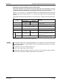
Art. no.: 226857
A
B
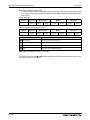
Version
04/2008 pdp
07/2008 pdp
Changes / Additions / Corrections
—
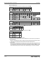
General
Expansion of the range of models by the inverters FR-D720S for
connection to a single-phase power supply
Section 6.18.5 Instruction Code (Multi command)
Addition of rated device current for frequency inverters
Appendix A
FR-D740-012 to 160 by the value for 40°C
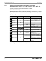
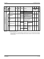
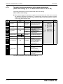
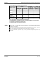
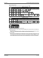
C
07/2010
akl
General
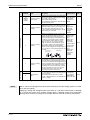
Section 7.6
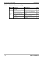
C1 09/2010
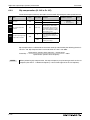
Page 3-34
Page 3-35
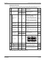
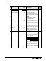
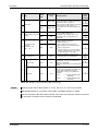
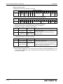
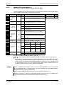
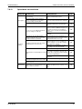
Setting values "80, 81, 180, 181" of Pr. 190 and Pr. 192
New parameter 197 "SO terminal function selection"
Initial value of Pr. 122 and Pr. 162
Safety stop function
Usage of a residual current device
Troubleshooting
Thermal Relay Type Name
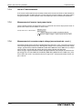
Thank you for choosing this Mitsubishi inverter.
This instruction manual provides instructions for advanced use of the FR-D700 series inverters.
Incorrect handling might cause an unexpected fault. Before using the inverter, always read this
instruction manual to use the equipment to its optimum.
Safety instructions
Do not attempt to install, operate, maintain or inspect the inverter until you have read through
this instruction manual carefully and can use the equipment correctly. Do not use the inverter until you have a full knowledge of the equipment, safety information and instructions. In this instruction manual, the safety instruction levels are classified into "WARNING" and "CAUTION".
P
WARNING:
E
CAUTION:
Assumes that incorrect handling may cause hazardous conditions, resulting in death
or severe injury.
Assumes that incorrect handling may cause hazardous conditions, resulting in medium or slight injury, or may cause physical damage only.
Note that even the CAUTION level may lead to a serious consequence according to conditions.
Please follow strictly the instructions of both levels because they are important to personnel
safety.
FR-D700 EC
I
Electric Shock Prevention
P
WARNING:
● While power is on or when the inverter is running, do not open the front cover.
Otherwise you may get an electric shock.
● Do not run the inverter with the front cover removed. Otherwise, you may access
the exposed high-voltage terminals or the charging part of the circuitry and get an
electric shock.
● Even if power is off, do not remove the front cover except for wiring or periodic
inspection. You may access the charged inverter circuits and get an electric shock.
● Before starting wiring or inspection, check to make sure that the operation panel
indicator is off, wait for at least 10 minutes after the power supply has been switched
off, and check that there are no residual voltage using a tester or the like. The
capacitor is charged with high voltage for some time after power off and it is
dangerous.
● This inverter must be earthed. Earthing must conform to the requirements of
national and local safety regulations and electrical codes. (JIS, NEC section 250,
IEC 536 class 1 and other applicable standards)
Use a neutral-point earthed (grounded) power supply for 400V class inverter in
compliance with EN standard.
● Any person who is involved in the wiring or inspection of this equipment should
be fully competent to do the work.
● Always install the inverter before wiring. Otherwise, you may get an electric shock
or be injured.
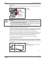
● If your application require by installation standards a RCD (residual current device)
as up stream protection please select according to DIN VDE 0100-530 as following:
Single phase inverter type A or B
Three phase inverter only type B
● Perform setting dial and key operations with dry hands to prevent an electric shock.
Otherwise you may get an electric shock.
● Do not subject the cables to scratches, excessive stress, heavy loads or pinching.
Otherwise you may get an electric shock.
● Do not replace the cooling fan while power is on. It is dangerous to replace the
cooling fan while power is on.
● Do not touch the printed circuit board with wet hands. You may get an electric shock.
● When measuring the main circuit capacitor capacity, the DC voltage is applied to
the motor for 1s at powering off. Never touch the motor terminal, etc. right after
powering off to prevent an electric shock.
II
Fire Prevention
E
CAUTION:
● Mount the inverter to incombustible material. Install the inverter on a nonflammable
wall without holes (so that nobody can touch the inverter heatsink on the rear side,
etc.). Mounting it to or near combustible material can cause a fire.
● If the inverter has become faulty, switch off the inverter power. A continuous flow
of large current could cause a fire.
● When using a brake resistor, make up a sequence that will turn off power when an
alarm signal is output. Otherwise, the brake resistor may excessively overheat due
to damage of the brake transistor and such, causing a fire.
● Do not connect a resistor directly to the DC terminals +, –. This could cause a fire
and destroy the inverter. The surface temperature of braking resistors can far
exceed 100°C for brief periods. Make sure that there is adequate protection against
accidental contact and a safe distance is maintained to other units and system
parts.
Injury Prevention
E
CAUTION:
● Apply only the voltage specified in the instruction manual to each terminal. Otherwise, burst, damage, etc. may occur.
● Ensure that the cables are connected to the correct terminals. Otherwise, burst,
damage, etc. may occur.
● Always make sure that polarity is correct to prevent damage, etc. Otherwise, burst,
damage, etc. may occur.
● While power is on or for some time after power-off, do not touch the inverter as it
is hot and you may get burnt.
FR-D700 EC
III
Additional Instructions
Also note the following points to prevent an accidental failure, injury, electric shock, etc.
Transport und Installation
E
CAUTION:
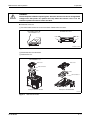
● Transport the product using the correct method that corresponds to the weight.
Failure to observe this could lead to injuries.
● Do not stack the inverter boxes higher than the number recommended.
● Ensure that installation position and material can withstand the weight of the
inverter. Install according to the information in the instruction manual.
● Do not install or operate the inverter if it is damaged or has parts missing. This can
result in breakdowns.
● When carrying the inverter, do not hold it by the front cover or setting dial; it may
fall off or fail.
● Do not stand or rest heavy objects on the product.
● Check the inverter mounting orientation is correct.
● Prevent other conductive bodies such as screws and metal fragments or other
flammable substance such as oil from entering the inverter.
● As the inverter is a precision instrument, do not drop or subject it to impact.
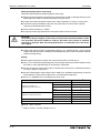
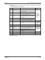
● Use the inverter under the following environmental conditions. Otherwise, the
inverter may be damaged.
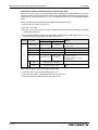
Operating Condition
Specifications
Ambient temperature
−10°C to +50°C (non-freezing)
Ambient humidity
90% RH or less (non-condensing)
Storage temperature
−20°C to +65°C Atmosphere
Indoors (free from corrosive gas, flammable gas, oil mist, dust and dirt)
Altitude
Maximum 1000m above sea level for standard operation. After that derate by 3% for
every extra 500m up to 2500m (91%)
Vibration
5.9m/s2 or less at 10 to 55Hz (directions of X, Y, Z axes)
Temperature applicable for a short time, e.g. in transit.
Wiring
E
IV
CAUTION:
● Do not install assemblies or components (e. g. power factor correction capacitors)
on the inverter output side, which are not approved from Mitsubishi.
● The direction of rotation of the motor corresponds to the direction of rotation
commands (STF/STR) only if the phase sequence (U, V, W) is maintained.
Trial run
E
CAUTION:
● Before starting operation, confirm and adjust the parameters. A failure to do so
may cause some machines to make unexpected motions.
Operation
P
WARNING:
● When you have chosen the retry function, stay away from the equipment as it will
restart suddenly after an alarm stop.
● Since pressing STOP/RESET key may not stop output depending on the function
setting status, provide a circuit and switch separately to make an emergency stop
(power off, mechanical brake operation for emergency stop, etc)
● Make sure that the start signal is off before resetting the inverter alarm. A failure
to do so may restart the motor suddenly.
● The load used should be a three-phase induction motor only. Connection of any
other electrical equipment to the inverter output may damage the equipment.
● Do not modify the equipment.
● Do not perform parts removal which is not instructed in this manual. Doing so may
lead to fault or damage of the inverter.
FR-D700 EC
V
E
CAUTION:
● The electronic thermal relay function does not guarantee protection of the motor
from overheating. It is recommended to install both an external thermal and PTC
thermistor for overheat protection.
● Do not use a magnetic contactor on the inverter input for frequent starting/stopping
of the inverter. Otherwise, the life of the inverter decreases.
● Use a noise filter to reduce the effect of electromagnetic interference and follow
the accepted EMC procedures for proper installation of frequency inverters. Otherwise nearby electronic equipment may be affected.
● Take appropriate measures regarding harmonics. Otherwise this can endanger
compensation systems or overload generators.
● Use a motor designed for inverter operation. (The stress for motor windings is
bigger than in line power supply).
● When parameter clear or all clear is performed, set again the required parameters
before starting operations. Each parameter returns to the initial value.
● The inverter can be easily set for high-speed operation. Before changing its setting,
fully examine the performances of the motor and machine.
● The DC braking function of the frequency inverter is not designed to continuously
hold a load. Use an electro-mechanical holding brake on the motor for this purpose.
● Before running an inverter which had been stored for a long period, always perform
inspection and test operation.
● For prevention of damage due to static electricity, touch nearby metal before
touching this product to eliminate static electricity from your body.
Emergency stop
E
CAUTION:
● Provide a safety backup such as an emergency brake which will prevent the
machine and equipment from hazardous conditions if the inverter fails.
● When the breaker on the inverter primary side trips, check for the wiring fault (short
circuit), damage to internal parts of the inverter, etc. Identify the cause of the trip,
then remove the cause and power on the breaker.
● When the protective function is activated (i. e. the frequency inverter switches off
with an error message), take the corresponding corrective action as described in
the inverter manual, then reset the inverter, and resume operation.
Maintenance, inspection and parts replacement
E
VI
CAUTION:
● Do not carry out a megger (insulation resistance) test on the control circuit of the
inverter. It will cause a failure.
Disposing the inverter
E
CAUTION:
● Treat as industrial waste.
General instructions
Many of the diagrams and drawings in instruction manuals show the inverter without a cover, or
partially open. Never run the inverter in this status. Always replace the cover and follow this instruction manual when operating the inverter.
FR-D700 EC
VII
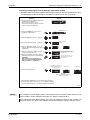
Typographic Conventions
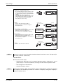
Use of notes
Notes containing important information are clearly identified as follows:
NOTE
Note text
Use of examples
Examples containing important information are clearly identified as follows:
Example 쑴
Example text
쑶
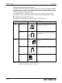
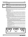
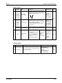
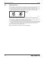
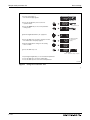
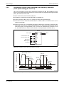
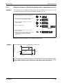
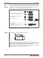
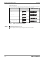
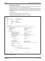
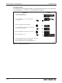
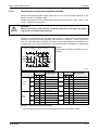
Numbering in figures and illustrations
Reference numbers in figures and illustrations are shown with white numbers in a black circle
and the corresponding explanations shown beneath the illustrations are identified with the same
numbers, like this:
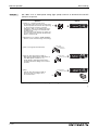
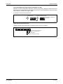
Procedures
In some cases the setup, operation, maintenance and other instructions are explained with numbered procedures, which must be performed in the exact order shown:
The individual steps of these procedures are numbered in ascending order with black numbers
in a white circle.
Text
Text
Text
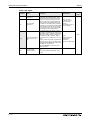
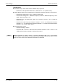
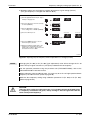
Footnotes in tables
Footnote characters in tables are printed in superscript and the corresponding footnotes shown
beneath the table are identified by the same characters, also in superscript.
If a table contains more than one footnote, they are all listed below the table and numbered in
ascending order with black numbers in a white circle, like this:
�
Text
Text
� Text
�
VIII
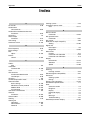
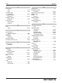
Contents
Contents
1
Product Checking and Part Identification
1.1
Inverter Type . . . . . . . . . . . . . . . . . . . . . . . . . . . . . . . . . . . . . . . . . . . . . . . . . . . 1-1
1.2
Description of the Case . . . . . . . . . . . . . . . . . . . . . . . . . . . . . . . . . . . . . . . . . . . 1-2
1.2.1
Accessory . . . . . . . . . . . . . . . . . . . . . . . . . . . . . . . . . . . . . . . . . . . . . . .1-3
2
Installation
2.1
Removal and reinstallation of the front cover . . . . . . . . . . . . . . . . . . . . . . . . . . . 2-1
2.1.1
FR-D720S-008 to 100 and FR-D740-012 to 080 . . . . . . . . . . . . . . . . . 2-1
2.1.2
FR-D740-120 and FR-D740-160. . . . . . . . . . . . . . . . . . . . . . . . . . . . . . 2-2
2.2
Removal and reinstallation of the wiring cover . . . . . . . . . . . . . . . . . . . . . . . . . . 2-4
2.3
Mounting. . . . . . . . . . . . . . . . . . . . . . . . . . . . . . . . . . . . . . . . . . . . . . . . . . . . . . . 2-5
2.4
Enclosure design . . . . . . . . . . . . . . . . . . . . . . . . . . . . . . . . . . . . . . . . . . . . . . . . 2-7
2.4.1
Inverter installation environment . . . . . . . . . . . . . . . . . . . . . . . . . . . . . . 2-7
2.4.2
Inverter placement . . . . . . . . . . . . . . . . . . . . . . . . . . . . . . . . . . . . . . . 2-11
3
Wiring
3.1
Inverter and peripheral devices . . . . . . . . . . . . . . . . . . . . . . . . . . . . . . . . . . . . .3-1
3.1.1
Peripheral devices. . . . . . . . . . . . . . . . . . . . . . . . . . . . . . . . . . . . . . . . .3-3
3.2
Terminal connection diagramm . . . . . . . . . . . . . . . . . . . . . . . . . . . . . . . . . . . . .3-4
3.3
Main circuit connection . . . . . . . . . . . . . . . . . . . . . . . . . . . . . . . . . . . . . . . . . . . .3-6
3.4
FR-D700 EC
3.3.1
Specification of main circuit terminal . . . . . . . . . . . . . . . . . . . . . . . . . . . 3-6
3.3.2
Terminal layout and wiring . . . . . . . . . . . . . . . . . . . . . . . . . . . . . . . . . .3-6
Control circuit specifications . . . . . . . . . . . . . . . . . . . . . . . . . . . . . . . . . . . . . . . 3-13
3.4.1
Control circuit terminals. . . . . . . . . . . . . . . . . . . . . . . . . . . . . . . . . . . . 3-17
3.4.2
Wiring instructions . . . . . . . . . . . . . . . . . . . . . . . . . . . . . . . . . . . . . . . .3-20
3.4.3
Safety stop function. . . . . . . . . . . . . . . . . . . . . . . . . . . . . . . . . . . . . . . 3-21
3.4.4
Changing the control logic. . . . . . . . . . . . . . . . . . . . . . . . . . . . . . . . . . 3-25
IX
Contents
3.5
3.6
3.7
PU connector . . . . . . . . . . . . . . . . . . . . . . . . . . . . . . . . . . . . . . . . . . . . . . . . . . 3-28
3.5.1
Connecting the parameter unit . . . . . . . . . . . . . . . . . . . . . . . . . . . . . .3-28
3.5.2
RS485 communication . . . . . . . . . . . . . . . . . . . . . . . . . . . . . . . . . . . .3-29
Connection of stand-alone option units . . . . . . . . . . . . . . . . . . . . . . . . . . . . . .3-30
3.6.1
Magnetic contactors (MC) . . . . . . . . . . . . . . . . . . . . . . . . . . . . . . . . . . 3-30
3.6.2
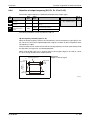
Connection of a dedicated external brake resistor FR-ABR and MRS
(FR-D720S-025 or more, FR-D740-012 or more) . . . . . . . . . . . . . . . .3-32
3.6.3
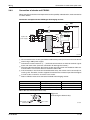
Connection of a brake unit FR-BU2 . . . . . . . . . . . . . . . . . . . . . . . . . . 3-35
3.6.4
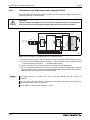
Connection of the high power factor converter FR-HC . . . . . . . . . . . . 3-38
3.6.5
Connection of the power regeneration common converter FR-CV . . .3-39
3.6.6
Connection of the power improving DC reactor FR-HEL . . . . . . . . . . 3-40
3.6.7
Installation of a reactor . . . . . . . . . . . . . . . . . . . . . . . . . . . . . . . . . . . .3-40
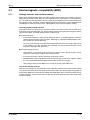
Electromagnetic compatibility (EMC) . . . . . . . . . . . . . . . . . . . . . . . . . . . . . . . . 3-41
3.7.1
Leakage currents and countermeasures. . . . . . . . . . . . . . . . . . . . . . . 3-41
3.7.2
Inverter-generated noises and their reduction techniques . . . . . . . . .3-45
3.7.3
Power supply harmonics . . . . . . . . . . . . . . . . . . . . . . . . . . . . . . . . . . .3-48
3.7.4
Inverter-driven 400V class motor . . . . . . . . . . . . . . . . . . . . . . . . . . . .3-49
4
Operation
4.1
Precautions for use of the inverter . . . . . . . . . . . . . . . . . . . . . . . . . . . . . . . . . . . 4-1
4.1.1
Failsafe of the system which uses the inverter . . . . . . . . . . . . . . . . . . . 4-3
4.2
Drive the motor . . . . . . . . . . . . . . . . . . . . . . . . . . . . . . . . . . . . . . . . . . . . . . . . . . 4-6
4.3
Operation panel . . . . . . . . . . . . . . . . . . . . . . . . . . . . . . . . . . . . . . . . . . . . . . . . . 4-7
4.3.1
Parts of the operation panel . . . . . . . . . . . . . . . . . . . . . . . . . . . . . . . . . 4-7
4.3.2
Basic operation (factory setting) . . . . . . . . . . . . . . . . . . . . . . . . . . . . . . 4-9
4.3.3
Easy operation mode setting (easy setting mode) . . . . . . . . . . . . . . .4-10
4.3.4
Operation lock . . . . . . . . . . . . . . . . . . . . . . . . . . . . . . . . . . . . . . . . . . .4-12
4.3.5
Monitoring of output current and output voltage . . . . . . . . . . . . . . . . .4-14
4.3.6
First priority monitor . . . . . . . . . . . . . . . . . . . . . . . . . . . . . . . . . . . . . .4-14
4.3.7
Digital dial push . . . . . . . . . . . . . . . . . . . . . . . . . . . . . . . . . . . . . . . . . . 4-14
4.3.8
Change the parameter setting value . . . . . . . . . . . . . . . . . . . . . . . . . . 4-15
4.3.9
Parameter clear/All Parameter clear . . . . . . . . . . . . . . . . . . . . . . . . . . 4-16
4.3.10 Initial value change list . . . . . . . . . . . . . . . . . . . . . . . . . . . . . . . . . . . .4-17
X
Contents
5
Basic settings
5.1
Simple mode parameter list . . . . . . . . . . . . . . . . . . . . . . . . . . . . . . . . . . . . . . . . 5-1
5.2
5.3
FR-D700 EC
5.1.1
Overheat protection of the motor by the inverter. . . . . . . . . . . . . . . . . .5-2
5.1.2
When the rated motor frequency is 60Hz (Pr. 3) . . . . . . . . . . . . . . . . . 5-4
5.1.3
Increase the starting torque (Pr. 0) . . . . . . . . . . . . . . . . . . . . . . . . . . . 5-5
5.1.4
Limit the maximum and minimum output frequency (Pr. 1, Pr. 2) . . . . . 5-7
5.1.5
Change the acceleration/deceleration time (Pr. 7, Pr. 8) . . . . . . . . . . . 5-9
5.1.6
Operation mode selection (Pr. 79) . . . . . . . . . . . . . . . . . . . . . . . . . . . 5-11
5.1.7
Large starting torque and low speed torque are necessary
(General-purpose magnetic flux vector control)
(Pr. 9, Pr. 71, Pr. 80) . . . . . . . . . . . . . . . . . . . . . . . . . . . . . . . . . . . . .5-12
5.1.8
To exhibit the best performance of the motor performance
(offline auto tuning)
(Pr. 9, Pr. 71, Pr. 80, Pr. 82 to Pr. 84, Pr. 90, Pr. 96) . . . . . . . . . . . . . 5-14
PU operation mode. . . . . . . . . . . . . . . . . . . . . . . . . . . . . . . . . . . . . . . . . . . . . . 5-21
5.2.1
Set the set frequency to operate . . . . . . . . . . . . . . . . . . . . . . . . . . . . . 5-22
5.2.2
Use the digital dial like a potentiometer to perform operation . . . . . . . 5-24
5.2.3
Use switches to give the frequency command (multi-speed setting) .5-25
5.2.4
Perform frequency setting by analog voltage input . . . . . . . . . . . . . . . 5-27
5.2.5
Perform frequency setting by analog current input . . . . . . . . . . . . . . . 5-29
External operation . . . . . . . . . . . . . . . . . . . . . . . . . . . . . . . . . . . . . . . . . . . . . .5-31
5.3.1
Use the set frequency set by PU (Pr. 79 = 3) . . . . . . . . . . . . . . . . . . . 5-31
5.3.2
Use switches to give a start command and a frequency command
(multi-speed setting) (Pr. 4 to Pr. 6) . . . . . . . . . . . . . . . . . . . . . . . . . . 5-33
5.3.3
Perform frequency setting by analog voltage input . . . . . . . . . . . . . . . 5-36
5.3.4
Change the frequency (40Hz) of the maximum value
of potentiometer (at 5V) . . . . . . . . . . . . . . . . . . . . . . . . . . . . . . . . . . . 5-39
5.3.5
Perform frequency setting by analog current input . . . . . . . . . . . . . . . 5-40
5.3.6
Change the frequency (40Hz) of the maximum value
of potentiometer (at 20mA) . . . . . . . . . . . . . . . . . . . . . . . . . . . . . . . . . 5-42
XI
Contents
6
Parameter
6.1
Parameter overview . . . . . . . . . . . . . . . . . . . . . . . . . . . . . . . . . . . . . . . . . . . . . . 6-1
6.2
Adjust the output torque (current) of the motor. . . . . . . . . . . . . . . . . . . . . . . . . 6-26
6.3
6.4
6.5
6.6
6.7
6.8
XII
6.2.1
Manual torque boost (Pr. 0, Pr. 46) . . . . . . . . . . . . . . . . . . . . . . . . . . 6-26
6.2.2
General-purpose magnetic flux vector control
(Pr. 9, Pr. 71, Pr. 80) . . . . . . . . . . . . . . . . . . . . . . . . . . . . . . . . . . . . . 6-29
6.2.3
Slip compensation (Pr. 245 to Pr. 247) . . . . . . . . . . . . . . . . . . . . . . . .6-32
6.2.4
Stall prevention operation
(Pr. 22, Pr. 23, Pr. 48, Pr. 66, Pr. 156, Pr. 157) . . . . . . . . . . . . . . . . .6-33
Limit the output frequency . . . . . . . . . . . . . . . . . . . . . . . . . . . . . . . . . . . . . . . . 6-40
6.3.1
Maximum and minimum frequency (Pr. 1, Pr. 2, Pr. 18) . . . . . . . . . . .6-40
6.3.2
Avoid mechanical resonance points (frequency jumps)
(Pr. 31 to Pr. 36) . . . . . . . . . . . . . . . . . . . . . . . . . . . . . . . . . . . . . . . . .6-42
Set V/f pattern. . . . . . . . . . . . . . . . . . . . . . . . . . . . . . . . . . . . . . . . . . . . . . . . . . 6-44
6.4.1
Base frequency, voltage (Pr. 3, Pr. 19, Pr. 47) . . . . . . . . . . . . . . . . .6-44
6.4.2
Load pattern selection (Pr. 14) . . . . . . . . . . . . . . . . . . . . . . . . . . . . . .6-46
Frequency setting by external terminals. . . . . . . . . . . . . . . . . . . . . . . . . . . . . .6-48
6.5.1
Multi-speed setting operation
(Pr. 4 to Pr. 6, Pr. 24 to Pr. 27, Pr. 232 to Pr. 239) . . . . . . . . . . . . . . . 6-48
6.5.2
Jog operation (Pr. 15, Pr. 16) . . . . . . . . . . . . . . . . . . . . . . . . . . . . . . . 6-51
6.5.3
Remote setting function (Pr. 59) . . . . . . . . . . . . . . . . . . . . . . . . . . . . . 6-55
Acceleration and deceleration . . . . . . . . . . . . . . . . . . . . . . . . . . . . . . . . . . . . . 6-59
6.6.1
Acceleration and deceleration time
(Pr. 7, Pr. 8, Pr. 20, Pr. 44, Pr. 45) . . . . . . . . . . . . . . . . . . . . . . . . . . . 6-59
6.6.2
Starting frequency and start-time hold function. . . . . . . . . . . . . . . . . . 6-62
6.6.3
Acceleration and deceleration pattern (Pr. 29) . . . . . . . . . . . . . . . . . . 6-64
Selection and protection of a motor . . . . . . . . . . . . . . . . . . . . . . . . . . . . . . . . .6-66
6.7.1
Motor overheat protection (Electronic thermal O/L relay)
(Pr. 9, Pr. 51, Pr. 561) . . . . . . . . . . . . . . . . . . . . . . . . . . . . . . . . . . . . .6-66
6.7.2
Applied motor (Pr. 71, Pr. 450) . . . . . . . . . . . . . . . . . . . . . . . . . . . . . .6-72
6.7.3
To exhibit the best performance of the motor performance
(offline auto tuning)
(Pr. 71, Pr. 80, Pr. 82 to Pr. 84, Pr. 90, Pr. 96) . . . . . . . . . . . . . . . . . . 6-74
Motor brake and stop operation . . . . . . . . . . . . . . . . . . . . . . . . . . . . . . . . . . . .6-81
6.8.1
DC injection brake (Pr. 10 to Pr. 12) . . . . . . . . . . . . . . . . . . . . . . . . . . 6-81
6.8.2
Selection of a regenerative brake (Pr. 30, Pr. 70) . . . . . . . . . . . . . . . .6-84
6.8.3
Stop selection (Pr. 250). . . . . . . . . . . . . . . . . . . . . . . . . . . . . . . . . . . . 6-86
Contents
6.9
6.10
Function assignment of external terminals . . . . . . . . . . . . . . . . . . . . . . . . . . . . 6-88
6.9.1
Input terminal function selection (Pr. 178 to Pr. 182) . . . . . . . . . . . . . 6-88
6.9.2
Inverter output shutoff signal (MRS signal, Pr. 17) . . . . . . . . . . . . . . . 6-91
6.9.3
Condition selection of function validity
by second function selection signal (RT, Pr. 155) . . . . . . . . . . . . . . . .6-93
6.9.4
Start signal selection (Terminal STF, STR, STOP, Pr. 250) . . . . . . . . 6-94
6.9.5
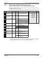
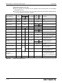
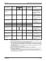
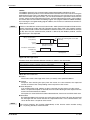
Output terminal function selection (Pr. 190, Pr. 192, Pr. 197). . . . . . . 6-98
6.9.6
Detection of output frequency (SU, FU, Pr. 41 to Pr. 43) . . . . . . . . .6-103
6.9.7
Output current detection function
(Y12, Y13, Pr. 150 to Pr. 153, Pr. 166, Pr. 167) . . . . . . . . . . . . . . . .6-105
6.9.8
Remote output function (REM, Pr. 495, Pr. 496) . . . . . . . . . . . . . . .6-107
Monitor display and monitor output signals . . . . . . . . . . . . . . . . . . . . . . . . . .6-109
6.10.1 Speed display and speed setting (Pr. 37) . . . . . . . . . . . . . . . . . . . . .6-109
6.10.2 Monitor display selection of DU/PU and terminal AM (Pr. 52,
Pr. 158, Pr. 170, Pr. 171, Pr. 268, Pr. 563, Pr. 564, Pr. 891) . . . . . .6-111
6.10.3 Reference of the terminal AM (analog voltage output)
(Pr. 55, Pr. 56). . . . . . . . . . . . . . . . . . . . . . . . . . . . . . . . . . . . . . . . . .6-118
6.10.4 Terminal AM calibration [C1 (Pr.901)] . . . . . . . . . . . . . . . . . . . . . . . .6-120
6.11
Operation selection at power failure . . . . . . . . . . . . . . . . . . . . . . . . . . . . . . . .6-123
6.11.1 Automatic restart (Pr. 30, Pr. 57, Pr. 58, Pr. 96, Pr. 162,
Pr. 165, Pr. 298, Pr. 299, Pr. 611). . . . . . . . . . . . . . . . . . . . . . . . . . .6-123
6.11.2 Power failure-time deceleration-to-stop function (Pr. 261) . . . . . . . .6-134
6.12
Operation setting at alarm occurrence . . . . . . . . . . . . . . . . . . . . . . . . . . . . . .6-138
6.12.1 Retry function (Pr. 65, Pr. 67 to Pr. 69) . . . . . . . . . . . . . . . . . . . . . . .6-138
6.12.2 Input/output phase failure protection selection (Pr. 251, Pr. 872) . . .6-141
6.12.3 Earth (ground) fault detection at start (Pr. 249). . . . . . . . . . . . . . . . .6-142
6.13
Energy saving operation. . . . . . . . . . . . . . . . . . . . . . . . . . . . . . . . . . . . . . . . .6-143
6.13.1 Optimum excitation control (Pr. 60) . . . . . . . . . . . . . . . . . . . . . . . . .6-143
6.14
Motor noise, EMI measures, mechanical resonance . . . . . . . . . . . . . . . . . . .6-144
6.14.1 PWM carrier frequency and soft-PWM control
(Pr. 72, Pr. 240, Pr. 260) . . . . . . . . . . . . . . . . . . . . . . . . . . . . . . . . . .6-144
6.14.2 Speed smoothing control (Pr. 653) . . . . . . . . . . . . . . . . . . . . . . . . . .6-146
6.15
Frequency setting by analog input (terminal 2, 4) . . . . . . . . . . . . . . . . . . . . .6-147
6.15.1 Analog input selection (Pr. 73, Pr. 267) . . . . . . . . . . . . . . . . . . . . . .6-147
6.15.2 Input filter time constant (Pr. 74) . . . . . . . . . . . . . . . . . . . . . . . . . . . .6-152
6.15.3 Bias and gain of frequency setting voltage (current)
[Pr. 125, Pr. 126, Pr. 241, C2 (Pr. 902) to C7 (Pr. 905)] . . . . . . . . . .6-153
FR-D700 EC
XIII
Contents
6.16
Misoperation prevention and parameter setting restriction. . . . . . . . . . . . . . .6-160
6.16.1 Reset selection/disconnected PU detection/PU stop selection
(Pr. 75) . . . . . . . . . . . . . . . . . . . . . . . . . . . . . . . . . . . . . . . . . . . . . . .6-160
6.16.2 Parameter write selection (Pr. 77). . . . . . . . . . . . . . . . . . . . . . . . . . .6-165
6.16.3 Reverse rotation prevention selection (Pr. 78) . . . . . . . . . . . . . . . . .6-167
6.16.4 Extended parameter display (Pr. 160) . . . . . . . . . . . . . . . . . . . . . . .6-168
6.16.5 Password function (Pr. 296, Pr. 297) . . . . . . . . . . . . . . . . . . . . . . . .6-169
6.17
Selection of operation mode and operation location . . . . . . . . . . . . . . . . . . .6-172
6.17.1 Operation mode selection (Pr. 79) . . . . . . . . . . . . . . . . . . . . . . . . . .6-172
6.17.2 Operation mode at power on (Pr. 79, Pr. 340) . . . . . . . . . . . . . . . . .6-184
6.17.3 Start command source and frequency command source during
communication operation (Pr. 338, Pr. 339, Pr. 551) . . . . . . . . . . . .6-186
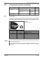
6.18
Communication operation and settings . . . . . . . . . . . . . . . . . . . . . . . . . . . . .6-193
6.18.1 PU connector . . . . . . . . . . . . . . . . . . . . . . . . . . . . . . . . . . . . . . . . . .6-193
6.18.2 Initial settings and specifications of RS485 communication
(Pr. 117 to Pr. 120, Pr. 123, Pr. 124, Pr. 549) . . . . . . . . . . . . . . . . . .6-198
6.18.3 Operation selection at communication error occurrence
(Pr. 121, Pr. 122, Pr. 502) . . . . . . . . . . . . . . . . . . . . . . . . . . . . . . . . .6-199
6.18.4 Communication E²PROM write selection (Pr. 342) . . . . . . . . . . . . . .6-204
6.18.5 Mitsubishi inverter protocol (computer link communication) . . . . . . .6-205
6.18.6 Modbus-RTU communication
(Pr. 117, Pr. 118, Pr. 120, Pr. 122, Pr. 343, Pr. 549) . . . . . . . . . . . .6-223
6.19
Special operation . . . . . . . . . . . . . . . . . . . . . . . . . . . . . . . . . . . . . . . . . . . . . .6-241
6.19.1 PID control (Pr. 127 to Pr. 134, Pr. 575 to Pr. 577). . . . . . . . . . . . . .6-241
6.19.2 Dancer control (Pr. 44, Pr. 45, Pr. 128 to Pr. 134) . . . . . . . . . . . . . .6-254
6.19.3 Traverse function (Pr. 592 to Pr. 597) . . . . . . . . . . . . . . . . . . . . . . . .6-263
6.19.4 Regeneration avoidance function
(Pr. 665, Pr. 882, Pr. 883, Pr. 885, Pr. 886) . . . . . . . . . . . . . . . . . . .6-266
6.20
Useful functions . . . . . . . . . . . . . . . . . . . . . . . . . . . . . . . . . . . . . . . . . . . . . . .6-269
6.20.1 Cooling fan operation selection (Pr. 244) . . . . . . . . . . . . . . . . . . . . .6-269
6.20.2 Display of the life of the inverter parts (Pr. 255 to Pr. 259) . . . . . . . .6-270
6.20.3 Maintenance timer alarm (Pr. 503, Pr. 504) . . . . . . . . . . . . . . . . . . .6-275
6.20.4 Current average value monitor signal (Pr. 555 to Pr. 557) . . . . . . . .6-276
6.20.5 Free parameters (Pr. 888, Pr. 889) . . . . . . . . . . . . . . . . . . . . . . . . . .6-280
XIV
Contents
6.21
Setting for the parameter unit, operation panel . . . . . . . . . . . . . . . . . . . . . . .6-281
6.21.1 RUN key rotation direction selection (Pr. 40) . . . . . . . . . . . . . . . . . .6-281
6.21.2 PU display language selection (Pr. 145) . . . . . . . . . . . . . . . . . . . . . .6-281
6.21.3 Operation panel frequency setting/key lock operation selection
(Pr. 161) . . . . . . . . . . . . . . . . . . . . . . . . . . . . . . . . . . . . . . . . . . . . . .6-282
6.21.4 Magnitude of frequency change setting (Pr. 295) . . . . . . . . . . . . . . .6-283
6.21.5 Buzzer control (Pr. 990) . . . . . . . . . . . . . . . . . . . . . . . . . . . . . . . . . .6-284
6.21.6 PU contrast adjustment (Pr. 991) . . . . . . . . . . . . . . . . . . . . . . . . . . .6-284
7
Troubleshooting
7.1
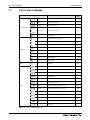
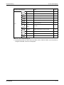
List of alarm display . . . . . . . . . . . . . . . . . . . . . . . . . . . . . . . . . . . . . . . . . . . . . . 7-2
7.2
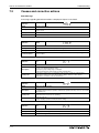
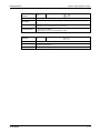
Causes and corrective actions . . . . . . . . . . . . . . . . . . . . . . . . . . . . . . . . . . . . . .7-4
7.3
Reset method of protective function . . . . . . . . . . . . . . . . . . . . . . . . . . . . . . . . . 7-17
7.4
LED display . . . . . . . . . . . . . . . . . . . . . . . . . . . . . . . . . . . . . . . . . . . . . . . . . . .7-18
7.5
Check and clear of the fault history . . . . . . . . . . . . . . . . . . . . . . . . . . . . . . . . .7-19
7.6
Check first when you have troubles . . . . . . . . . . . . . . . . . . . . . . . . . . . . . . . . .7-21
7.6.1
Motor does not start . . . . . . . . . . . . . . . . . . . . . . . . . . . . . . . . . . . . . .7-21
7.6.2
Motor or machine generates abnormal noise . . . . . . . . . . . . . . . . . . . 7-23
7.6.3
Inverter generates abnormal noise . . . . . . . . . . . . . . . . . . . . . . . . . . .7-23
7.6.4
Motor generates heat abnormally . . . . . . . . . . . . . . . . . . . . . . . . . . . . 7-24
7.6.5
Motor rotates in opposite direction . . . . . . . . . . . . . . . . . . . . . . . . . . . 7-24
7.6.6
Speed greatly differs from the setting . . . . . . . . . . . . . . . . . . . . . . . . . 7-24
7.6.7
Acceleration/deceleration is not smooth . . . . . . . . . . . . . . . . . . . . . . . 7-25
7.6.8
Speed varies during operation . . . . . . . . . . . . . . . . . . . . . . . . . . . . . .7-26
7.6.9
Operation mode is not changed properly . . . . . . . . . . . . . . . . . . . . . .7-27
7.6.10 Operation panel display is not operating . . . . . . . . . . . . . . . . . . . . . . . 7-27
7.6.11 Motor current is too large . . . . . . . . . . . . . . . . . . . . . . . . . . . . . . . . . . 7-28
7.6.12 Speed does not accelerate . . . . . . . . . . . . . . . . . . . . . . . . . . . . . . . . . 7-29
7.6.13 Unable to write parameter setting . . . . . . . . . . . . . . . . . . . . . . . . . . . . 7-30
7.7
FR-D700 EC
Meters and measuring methods . . . . . . . . . . . . . . . . . . . . . . . . . . . . . . . . . . . . 7-31
7.7.1
Measurement of powers . . . . . . . . . . . . . . . . . . . . . . . . . . . . . . . . . . . 7-32
7.7.2
Measurement of voltages and use of PT . . . . . . . . . . . . . . . . . . . . . .7-33
7.7.3
Measurement of currents . . . . . . . . . . . . . . . . . . . . . . . . . . . . . . . . . . 7-33
7.7.4
Use of CT and transducer . . . . . . . . . . . . . . . . . . . . . . . . . . . . . . . . . . 7-34
7.7.5
Measurement of inverter input power factor . . . . . . . . . . . . . . . . . . . .7-34
7.7.6
Measurement of converter output voltage (across terminals + and –). . . 7-34
XV
Contents
8
Maintenance and inspection
8.1
Inspection . . . . . . . . . . . . . . . . . . . . . . . . . . . . . . . . . . . . . . . . . . . . . . . . . . . . . .8-1
8.2
XVI
8.1.1
Daily inspection . . . . . . . . . . . . . . . . . . . . . . . . . . . . . . . . . . . . . . . . . . . 8-1
8.1.2
Periodic inspection . . . . . . . . . . . . . . . . . . . . . . . . . . . . . . . . . . . . . . . . 8-1
8.1.3
Daily and periodic inspection . . . . . . . . . . . . . . . . . . . . . . . . . . . . . . . . 8-2
8.1.4
Display of the life of the inverter parts . . . . . . . . . . . . . . . . . . . . . . . . . . 8-4
8.1.5
Checking the inverter and converter modules. . . . . . . . . . . . . . . . . . . .8-5
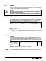
8.1.6
Cleaning . . . . . . . . . . . . . . . . . . . . . . . . . . . . . . . . . . . . . . . . . . . . . . . . 8-6
8.1.7
Replacement of parts . . . . . . . . . . . . . . . . . . . . . . . . . . . . . . . . . . . . . . 8-6
Measurements on the main circuit . . . . . . . . . . . . . . . . . . . . . . . . . . . . . . . . . . 8-10
8.2.1
Insulation resistance test using megger . . . . . . . . . . . . . . . . . . . . . . .8-10
8.2.2
Pressure test . . . . . . . . . . . . . . . . . . . . . . . . . . . . . . . . . . . . . . . . . . . . 8-10
8.2.3
Measurement of voltages and currents . . . . . . . . . . . . . . . . . . . . . . . .8-11
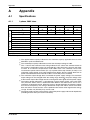
A
Appendix
A.1
Specifications . . . . . . . . . . . . . . . . . . . . . . . . . . . . . . . . . . . . . . . . . . . . . . . . . A-1
A.1.1
1-phase, 200V class . . . . . . . . . . . . . . . . . . . . . . . . . . . . . . . . . . . . . . A-1
8.2.4
3-phase, 400V class . . . . . . . . . . . . . . . . . . . . . . . . . . . . . . . . . . . . . . A-2
A.2
Common specifications . . . . . . . . . . . . . . . . . . . . . . . . . . . . . . . . . . . . . . . . . . A-3
A.3
Outline dimension drawings . . . . . . . . . . . . . . . . . . . . . . . . . . . . . . . . . . . . . . A-5
A.3.1
FR-D720S-008 to 042 . . . . . . . . . . . . . . . . . . . . . . . . . . . . . . . . . . . . A-5
A.3.2
FR-D720S-070 and FR-D740-012 to 080 . . . . . . . . . . . . . . . . . . . . . A-6
A.3.3
FR-D720S-100 . . . . . . . . . . . . . . . . . . . . . . . . . . . . . . . . . . . . . . . . . . A-7
A.3.4
FR-D740-120 and 160 . . . . . . . . . . . . . . . . . . . . . . . . . . . . . . . . . . . . A-8
A.3.5
Parameter unit FR-PU07 . . . . . . . . . . . . . . . . . . . . . . . . . . . . . . . . . . A-9
A.3.6
Parameter unit FR-PA07 . . . . . . . . . . . . . . . . . . . . . . . . . . . . . . . . . A-10
A.4
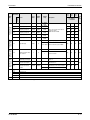
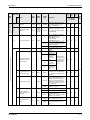
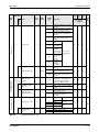
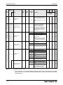
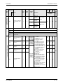
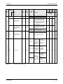
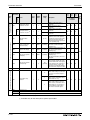
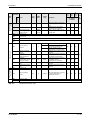
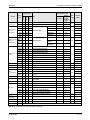
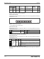
Parameter list with instruction codes . . . . . . . . . . . . . . . . . . . . . . . . . . . . . . . A-11
A.5
Specification change . . . . . . . . . . . . . . . . . . . . . . . . . . . . . . . . . . . . . . . . . . . A-19
A.5.1
SERIAL number check . . . . . . . . . . . . . . . . . . . . . . . . . . . . . . . . . . . A-19
A.5.2
Changed functions . . . . . . . . . . . . . . . . . . . . . . . . . . . . . . . . . . . . . . A-19
Product Checking and Part Identification
1
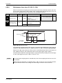
Inverter Type
Product Checking and Part Identification
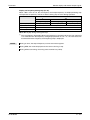
Unpack the inverter and check the capacity plate on the front cover and the rating plate on the
inverter side face to ensure that the product agrees with your order and the inverter is intact.
1.1
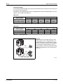
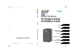
Inverter Type
Symbol
Voltage Class
Symbol
Type number
D720S
Single-phase 230V
D740
Three-phase 400V class
008
to
160
3-digit display
I001965E
Fig. 1-1: Inverter Type FR-D700 EC
FR-D700 EC
1-1
Description of the Case
1.2
Product Checking and Part Identification
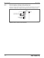
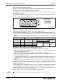
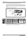
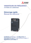
Description of the Case
Operation panel
(refer to section 4.3)
Cooling fan
(refer to section 8.1.7)
Voltage/current input switch
(refer to section 3.4)
PU connector
(siehe Abschn. 3.5)
Front cover
Standard control
circuit terminal block
(refer to section 3.4)
Changing the control
logic jumper connector
(refer to section 3.4.3)
Main circuit
terminal block
(refer to section 3.3)
Comb shaped
wiring cover
(refer to section 2.2)
Capacity plate
Rating plate
Inverter type
Serial number
Inverter type
Input rating
Output rating
Serial number
I001966E
Fig. 1-2: Appearance and Structure
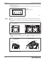
NOTE
1-2
For removal and reinstallation of covers, refer to section 2.1.
Product Checking and Part Identification
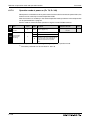
1.2.1
Description of the Case
Accessory
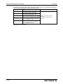
Fan cover fixing screws
Capacity
Screw Size [mm]
Number
FR-D720S-070 and 100
M3 × 35
1
FR-D740-036 to 080
M3 × 35
1
FR-D740-120 and 160
M3 × 35
2
Tab. 1-1: Fan cover fixing screws
NOTES
Inverters FR-D720S-008 to 042 and FR-D740-022 or less are not provided with the cooling
fan. Therefore the fan cover fixing screws are not delivered with these models.
For removal and reinstallation of the cooling fans, refer to section 8.1.7.
FR-D700 EC
1-3
Description of the Case
1-4
Product Checking and Part Identification
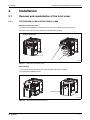
Installation
Removal and reinstallation of the front cover
2
Installation
2.1
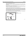
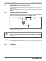
Removal and reinstallation of the front cover
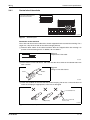
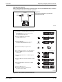
2.1.1
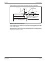
FR-D720S-008 to 100 and FR-D740-012 to 080
Removal of the front cover
Loosen the installation screw of the front cover. (This screw cannot be removed.)
Remove the front cover by pulling it like the direction of arrow.
Example: FR-D740-036
Installation screw
I001967E
Fig. 2-1: Removal of the front cover
Reinstallation
To reinstall, match the cover to the inverter front and install it straight.
Tighten the installation screw.
Example: FR-D740-036
Installation screw
I001968E
Fig. 2-2: Reinstallation of the front cover
FR-D700 EC
2-1
Removal and reinstallation of the front cover
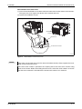
2.1.2
Installation
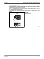
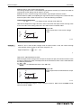
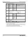
FR-D740-120 and FR-D740-160
Removal of the front cover
Loosen the installation screws of the front cover. (The screws cannot be removed.)
Remove the front cover by pulling it like the direction of arrow with holding the installation
hook on the front cover.
Example: FR-D740-160
Installation hook
Front
cover 1
Front
cover 2
Installation
screws
I001969E
Fig. 2-3: Removal of the front cover
2-2
Installation
Removal and reinstallation of the front cover
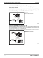
Reinstallation of the front cover
Insert the two fixed hooks on the lower side of the front cover into the sockets of the inverter.
Then press the cover against the device until it correctly locks on.
Tighten the installation screws.
Example: FR-D740-160
Installation
screws
Fixed hook
Socket of the inverter
I001970E
Fig. 2-4: Reinstallation of the front cover
NOTES
Fully make sure that the front cover has been reinstalled securely. Always tighten the installation screws of the front cover.
The same serial number is printed on the capacity plate of the front cover and the rating
plate of the inverter. Before reinstalling the front cover, check the serial numbers to ensure
that the cover removed is reinstalled to the inverter from where it was removed.
FR-D700 EC
2-3
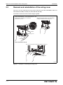
Removal and reinstallation of the wiring cover
2.2
Installation
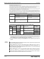
Removal and reinstallation of the wiring cover
The cover can be removed easily by pulling it downward (FR-D720S-008 to 100 and
FR-D740-012 to 080) or toward you (FR-D740-120 and 160).
To reinstall, fit the cover to the inverter along the guides.
Inverter FR-D720S-008 to 100 and FR-D740-012 to 080
Alternatively pull the wiring cover downward by
holding a frontal part of the wiring cover.
Hold the side of the wiring cover, and pull it
downward for removal.
Guides
Wiring cover
Inverter FR-D740-120 and 160
The cover can be removed easily by pulling it toward you.
Guide
Guide
Wiring cover
I002071E
Fig. 2-5: Examples for removing the wiring cover
2-4
Installation
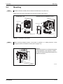
2.3
NOTE
Mounting
Mounting
Install the inverter vertically. Do not mount it horizontally or any other way.
Remove the front cover and wiring cover to fix the inverter to the surface.
FR-D720S-008 to 042
FR-D720S-070 and 100, FR-D740-012 to 160
Front cover
Front cover
Wiring cover
Wiring cover
I002030E
Fig. 2-6: Installation on the panel
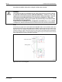
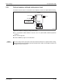
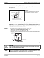
NOTE
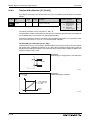
When encasing multiple inverters, install them in parallel as a cooling measure. Leave
enough clearances around the inverter (refer to page 2-11).
Vertical
Fig. 2-7:
Good heat dissipation is achieved through the
vertical alignment of the frequency inverter,
the side-by-side mounting and maintenance of
minimum clearances.
Refer to
FR-D700 EC
Fig. 2-9
fo
r the cle
arances
I001973E
2-5
Mounting
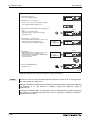
Installation
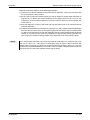
The inverter consists of precision mechanical and electronic parts. Never install or handle it in
any of the following conditions as doing so could cause an operation fault or failure.
Direct sunlight
Vibration (≥ 5,9 m/s²)
High temperature,
high humidity
Horizontal placement
(When mounted
inside enclosure.)
Transportation by holding
the front cover or dial
Oil mist, flammable gas,
corrosive gas, fluff, dust, etc.
Mounting to
combustible material
I001974E
Fig. 2-8: Conditions, that could cause an operation fault or failure
2-6
Installation
2.4
Enclosure design
Enclosure design
When an inverter enclosure is to be designed and manufactured, heat generated by contained
equipment, etc., the environment of an operating place, and others must be fully considered to
determine the enclosure structure, size and equipment layout.
The inverter unit uses many semiconductor devices. To ensure higher reliability and long period
of operation, operate the inverter in the ambient environment that completely satisfies the equipment specifications.
2.4.1
Inverter installation environment
As the inverter installation environment should satisfy the standard specifications indicated in
the following table, operation in any place that does not meet these conditions not only deteriorates the performance and life of the inverter, but also causes a failure. Refer to the following
points and take adequate measures.
Item
Specification
Ambient temperature
−10°C to +50°C (non-freezing)
Ambient humidity
90% RH or less (non-condensing)
Atmosphere
Free from corrosive and explosive gases, dust and dirt
Maximum altitude
1000m or less
Vibration
5.9m/s2 or less (0,6 g) at 10 to 55Hz (directions of X, Y, Z axes)
Tab. 2-1: Environmental standard specifications of inverter
Temperature
The permissible ambient temperature of the inverter FR-D700 is between −10 and +50°C. Always operate the inverter within this temperature range. Operation outside this range will considerably shorten the service lives of the semiconductors, parts, capacitors and others. Take the
following measures so that the ambient temperature of the inverter falls within the specified
range.
● Measures against high temperature
– Use a forced ventilation system or similar cooling system. (Refer to page 2-10.)
– Install the enclosure in an air-conditioned electrical chamber.
– Block direct sunlight.
– Provide a shield or similar plate to avoid direct exposure to the radiated heat and wind
of a heat source.
– Ventilate the area around the enclosure well.
● Measures against low temperature
– Provide a space heater in the enclosure.
– Do not power off the inverter. (Keep the start signal of the inverter off.)
● Sudden temperature changes
– Select an installation place where temperature does not change suddenly.
– Avoid installing the inverter near the air outlet of an air conditioner.
– If temperature changes are caused by opening/closing of a door, install the inverter away
from the door.
FR-D700 EC
2-7
Enclosure design
Installation
Humidity
Normally operate the inverter within the 45% to 90% range of the ambient humidity. Too high humidity will pose problems of reduced insulation and metal corrosion. On the other hand, too low
humidity may produce a spatial electrical breakdown. The insulation distance specified in
JEM1103 "Control Equipment Insulator" is defined as humidity 45% to 85%.
● Measures against high humidity
– Make the enclosure enclosed, and provide it with a hygroscopic agent.
– Take dry air into the enclosure from outside.
– Provide a space heater in the enclosure
● Measures against low humidity
What is important in fitting or inspection of the unit in this status is to discharge your body
(static electricity) beforehand and keep your body from contact with the parts and patterns,
besides blowing air of proper humidity into the enclosure from outside.
● Measures against condensation
Condensation may occur if frequent operation stops change the in-enclosure temperature
suddenly or if the outside air temperature changes suddenly. Condensation causes such
faults as reduced insulation and corrosion.
– Take the measures against high humidity.
– Do not power off the inverter. (Keep the start signal of the inverter off.)
Dust, dirt, oil mist
Dust and dirt will cause such faults as poor contact of contact points, reduced insulation or reduced cooling effect due to moisture absorption of accumulated dust and dirt, and in-enclosure
temperature rise due to clogged filter.
In the atmosphere where conductive powder floats, dust and dirt will cause such faults as malfunction, deteriorated insulation and short circuit in a short time. Since oil mist will cause similar
conditions, it is necessary to take adequate measures.
● Measures against dust, dirt, oil mist
– Place in a totally enclosed enclosure.
Take measures if the in-enclosure temperature rises. (Refer to page 2-10.)
– Purge air.
Pump clean air from outside to make the in-enclosure pressure higher than the outsideair pressure.
Corrosive gas, salt damage
If the inverter is exposed to corrosive gas or to salt near a beach, the printed board patterns and
parts will corrode or the relays and switches will result in poor contact. In such places, take the
measures against dust, dirt, oil mist.
2-8
Installation
Enclosure design
Explosive, flammable gases
As the inverter is non-explosion proof, it must be contained in an explosion proof enclosure.
In places where explosion may be caused by explosive gas, dust or dirt, an enclosure cannot be
used unless it structurally complies with the guidelines and has passed the specified tests. This
makes the enclosure itself expensive (including the test charges).
The best way is to avoid installation in such places and install the inverter in a non-hazardous
place.
Highland
Use the inverter at the altitude of within 1000m.
If it is used at a higher place, it is likely that thin air will reduce the cooling effect and low air pressure will deteriorate dielectric strength.
Maximum 1000m above sea level for standard operation. After that derate by 3% for every extra
500m up to 2500m (91%).
Vibration, impact
The vibration resistance of the inverter is up to 5.9m/s2 at 10 to 55Hz frequency and 1mm amplitude for the directions of X, Y, Z axes.
Vibration or impact, if less than the specified value, applied for a long time may make the mechanism loose or cause poor contact to the connectors. Especially when impact is imposed repeatedly, caution must be taken as the part pins are likely to break.
● Countermeasures
– Provide the enclosure with rubber vibration isolators.
– Strengthen the structure to prevent the enclosure from resonance.
– Install the enclosure away from sources of vibration.
FR-D700 EC
2-9
Enclosure design
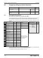
Installation
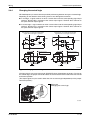
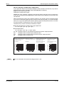
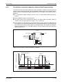
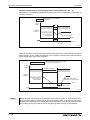
Cooling system types for inverter enclosure
From the enclosure that contains the inverter, the heat of the inverter and other equipment
(transformers, lamps, resistors, etc.) and the incoming heat such as direct sunlight must be dissipated to keep the in-enclosure temperature lower than the permissible temperatures of the inenclosure equipment including the inverter.
The cooling systems are classified as follows in terms of the cooling calculation method.
● Cooling by natural heat dissipation from the enclosure surface (Totally enclosed type)
● Cooling by heat sink (Aluminium fin, etc.)
● Cooling by ventilation (Forced ventilation type, pipe ventilation type)
● Cooling by heat exchanger or cooler (Heat pipe, cooler, etc.)
Cooling System
Natural
cooling
Enclosure Structure
Comment
Low in cost and generally used, but the enclosure
size increases as the inverter capacity increases.
For relatively small capacities.
Natural ventilation
(Enclosed, open type)
INV
I001000E
Being a totally enclosed type, the most appropriate
for hostile environment having dust, dirt, oil mist,
etc. The enclosure size increases depending on the
inverter capacity.
Natural ventilation
(Totally enclosed
type)
INV
I001001E
Forced
cooling
Having restrictions on the heatsink mounting position and area, and designed for relative small
capacities.
Heatsink cooling
heatsink
INV
I001002E
For general indoor installation. Appropriate for
enclosure downsizing and cost reduction, and often
used.
Forced ventilation
INV
I001003E
Heat pipe
heat pipe
Totally enclosed type for enclosure downsizing.
INV
I001004E
Tab. 2-2: Cooling system types for inverter enclosure
("INV" in in the figures stands for "inverter")
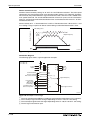
2 - 10
Installation
2.4.2
Enclosure design
Inverter placement
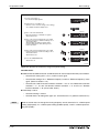
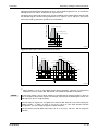
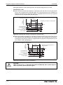
Clearances around the inverter
Always observe the specified minimum clearances to ensure good heat dissipation and adequate accessibility of the frequency inverter for servicing.
Clearances (side)
Clearances (front)
x = Measurement
position
≥ 10cm
5cm
≥ 1cm 5cm
≥ 1cm ≥ 1cm Inverter
5cm
Inverter
Ambient temperature and humidity
Temperature: −10°C to +50°C
Humidity: 90% RH maximum
≥ 10cm
Leave enough clearances and take
cooling measures.
When using the inverters at the
ambient temperature of 40°C or
less, the inverters can be
installed without any clearance
between them (0cm clearance).
When ambient temperature
exceeds 40°C, clearances
between the inverters should
be 1cm or more (5cm or more
for the FR-D740-120 or more).
≥ 5cm for the FR-D740-120
and more
I001975E
Fig. 2-9: Clearances
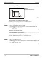
Inverter mounting orientation
Mount the inverter on a wall as specified. Do not mount it horizontally or any other way.
Above the inverter
Heat is blown up from inside the inverter by the small fan built in the unit. Any equipment placed
above the inverter should be heat resistant.
FR-D700 EC
2 - 11
Enclosure design
Installation
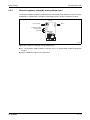
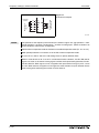
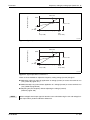
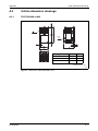
Arrangement of multiple inverters
When multiple inverters are placed in the same enclosure, generally arrange them horizontally
as shown in the figure (a). When it is inevitable to arrange them vertically to minimize space, take
such measures as to provide guides since heat from the bottom inverters can increase the temperatures in the top inverters, causing inverter failures.
Inverter
Inverter
Enclosure
Inverter
Inverter
Guide
Guide
Inverter
Inverter
Guide
Enclosure
a) Horizontal arrangement
b) Vertical arrangement
I001006E
Fig. 2-10: Arrangement of multiple inverters
NOTE
When mounting multiple inverters, fully take caution not to make the ambient temperature of
the inverter higher than the permissible value by providing ventilation and increasing the
enclosure size.
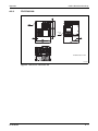
Placement of ventilation fan and inverter
Heat generated in the inverter is blown up from the bottom of the unit as warm air by the cooling
fan. When installing a ventilation fan for that heat, determine the place of ventilation fan installation after fully considering an air flow. (Air passes through areas of low resistance. Make an airway and airflow plates to expose the inverter to cool air.)
Inverter
Good example!
Inverter
Bad example!
I001007E
Fig. 2-11: Placement of ventilation fan and inverter
2 - 12
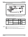
Wiring
Inverter and peripheral devices
3
Wiring
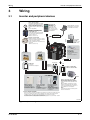
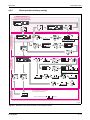
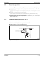
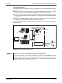
3.1
Inverter and peripheral devices
3-phase AC power supply
Use within the permissible power supply
specifications of the inverter. To ensure
safety, use a moulded case circuit
breaker, earth leakage circuit breaker or
magnetic contactor to switch power ON/
OFF.
(Refer to Appendix A.)
Parameter unit
(FR-PA07)
By connecting the
connection cable
(FR-A5CBL) to the
PU connector, operation can be performed
from FR-PA07.
Moulded case circuit breaker
(MCCB) or earth leakage circuit
breaker (ELB), fuse
The breaker ust be selected carefully
since an in-rush current flows in the
inverter at power on.
(Refer to section 3.1.1.)
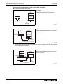
RS232C/RS485 converter is
required when connecting to
PC with RS232C interface.
RS232C/RS485
Converter SC-FR-PC
Magnetic contactor (MC)
Install the magnetic contactor to ensure
safety. Do not use this magnetic contactor
to start and stop the inverter.
Doing so will cause the inverter life to be
shortened.
(Refer to section 3.1.1.)
AC reactor
(FR-BAL-B) S1
S2
SC
Approved safety
relay module
Required for compliance with safety
standard.
Brake resistor
(FR-ABR, MRS)
Braking capability can be
improved.
Install this as required.
DC reactor
(FR-HEL) +
PR
+ P1
R/L1 S/L2 T/L3
EMC filter
(optional)
Install this as required.
Earth
U VW
Capacitor
type filter
(optional)
+
-
FFR-DT = Output filter
FFR-SI = Sine wave filter
Brake unit
(FR-BU2/BU-UFS)
Earth
P/+ PR
P/+
PR
High power factor
converter (FR-HC)
Power supply harmonics
can be greatly suppressed.
Install this as required.
Power regeneration
common converter
(FR-CV)
Greater braking capability
is obtained.
Install this as required.
Resistor unit (FR-BR)
Discharging resistor
(GZG, GRZG)
The regenerative braking
capability of the inverter can
be exhibited fully. Install this
as required.
Devices connected to the output
Do not install a power factor correction
capacitor, surge suppressor, arrester or
radio noise filter on the output side of the
inverter.
When installing a moulded case circuit
breaker on the output side of the inverter,
contact each manufacturer for selection of
the moulded case circuit breaker.
Earth
To prevent an electric shock, always earth
the motor and inverter.
Reactor (FR-BAL-B, FR-HEL)
Reactors (option) should be used when power harmonics measures are taken, the power
factor is to be improved or the inverter is installed near a large power supply system
(500kVA or more). The inverter may be damaged if you do not use reactors.
Select the reactor according to the model. Remove the jumpers across terminals + and P1
to connect to the DC reactor. (Refer to section 3.1.1).
I002070E
Fig. 3-1: System configuration overview
FR-D700 EC
3-1
Inverter and peripheral devices
NOTES
Wiring
The life of the inverter is influenced by surrounding air temperature. The surrounding air
temperature should be as low as possible within the permissible range. This must be noted
especially when the inverter is installed in an enclosure (refer to section 2.4.2).
Wrong wiring might lead to damage of the inverter. The control signal lines must be kept fully
away from the main circuit to protect them from noise (refer to section 3.2).
Do not install a power factor correction capacitor or surge suppressor on the inverter output
side. This will cause the inverter to trip or the capacitor and surge suppressor to be damaged. If any of the above devices are connected, immediately remove them.
Electromagnetic Compatibility
Operation of the frequency inverter can cause electromagnetic interference in the input and
output that can be propagated by cable (via the power input lines), by wireless radiation to
nearby equipment (e.g. AM radios) or via data and signal lines.
Activate the integrated EMC filter (and an additional optional filter if present) to reduce air
propagated interference on the input side of the inverter. Use AC or DC reactors to reduce
line propagated noise (harmonics). Use shielded motor power lines to reduce output noise
(refer also to section 3.7 Electromagnetic Compatibility).
Refer to the instruction manual of each option and peripheral devices for details of peripheral devices.
3-2
Wiring
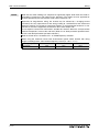
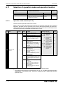
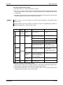
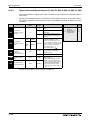
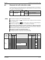
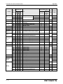
3.1.1
Inverter and peripheral devices
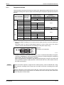
Peripheral devices
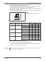
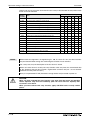
Check the motor capacity of the inverter you purchased. Appropriate peripheral devices must be
selected according to the capacity. Refer to the following list and prepare appropriate peripheral
devices:
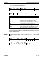
Motor output [kW]
Applicable Inverter Type
Breaker Selection Input Side Magnetic
Contactor Reactor connection
Reactor connection
Without
With
Without
With
0.1
FR-D720S-008
0.2
FR-D720S-014
0.4
FR-D720S-025
NF32 xx 3P 10 A NF32 xx 3P 6 A
0.75
FR-D720S-042
NF32 xx 3P 16 A NF32 xx 3P 10 A
1.5
FR-D720S-070
NF32 xx 3P 32 A NF32 xx 3P 16 A
2.2
FR-D720S-100
NF32 xx 3P 40 A NF32 xx 3P 32 A
0.4
FR-D740-012
0.75
FR-D740-022
1.5
FR-D740-036
NF32 xx 3P 10 A
2.2
FR-D740-050
NF32 xx 3P 16 A NF32 xx 3P 10 A
3.7
FR-D740-080
NF63 xx 3P 20 A NF32 xx 3P 16 A
5.5
FR-D740-120
NF63 xx 3P 32 A NF63 xx 3P 20 A
S-N20, S-N21
S-N11, S-N12
7.5
FR-D740-160
NF63 xx 3P 32 A
S-N20, S-N21
S-N20, S-N21
200V class
NF32 xx 3P 6 A
S-N10
S-N20,S-N21
S-N10
400V class
NF32 xx 3P 6 A
S-N10
Tab. 3-1: Breakers and contactors
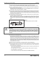
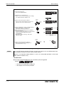
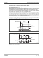
Select the MCCB according to the inverter power supply capacity. Install one MCCB per
inverter.
The places with "xx" refer to the breaking capacity in case of short circuit. The correct
selection must be done depending on the design of the power input wiring.
MCCB
Inverter
M
3~
MCCB
Inverter
M
3~
Fig. 3-2:
Installation of the breakers
I001332E
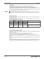
NOTES
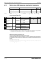
Magnetic contactor is selected based on the AC-1 class. The electrical durability of magnetic
contactor is 500,000 times. When the magnetic contactor is used for emergency stop during
motor driving, the electrical durability is 25 times.
When using the MC for emergency stop during motor driving or using on the motor side
during commercial-power supply operation, select the MC with class AC-3 rated current for
the motor rated current.
When the inverter capacity is larger than the motor capacity, select an MCCB and a magnetic contactor according to the inverter type and cable and reactor according to the motor
output.
When the breaker on the inverter primary side trips, check for the wiring fault (short circuit),
damage to internal parts of the inverter, etc. Identify the cause of the trip, then remove the
cause and power on the breaker.
FR-D700 EC
3-3
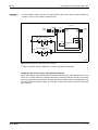
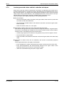
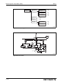
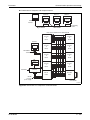
Terminal connection diagramm
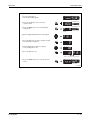
3.2
Wiring
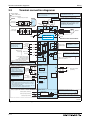
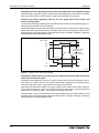
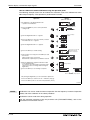
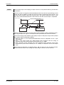
Terminal connection diagramm
Source Logic
*6 FR-D720S-008 to 100: +, –
FR-D740-012 to 160: P/+, N/–
*1 DC reactor
When connecting a DC reactor, remove the
jumper across P1 and +.
Main circuit terminal
Control circuit terminal
Single-phase power input
MCCB
Brake unit
(Option)
MC
L1
N
1-phase AC
power supply
*1
R
PR
Jumper
MCCB
+*6
P1
MC
R/L1
S/L2
T/L3
3-phase AC
power supply
*8 Brake resistor (FR-ABR, MRS)
Install a thermal relay to prevent an overheat
and burnout of the brake resistor.
(The brake resistor can not be connected to
the FR-D720S-008 and 014.).
*8
Earth
*7
*7 A brake transistor is not built-in to the
FR-D720S-008 and 014.
-*6
U
V
W
Inrush
current limit
circuit
M
3~
Motor
Main circuit
Earth
Earth
Control circuit
Standard control terminal block
Control input signals (No voltage input allowed)
Relay output
(Alarm output)
A
RH
High speed
Relay output
B
STR
Reverse
rotation start
RM
RL
Low speed
SD
Contact input common (sink*)
24V DC power supply/
max. 100mA load current
Contact input common (source*)
Running
24V
SE
Terminal functions vary with the input
terminal assignment set in Pr. 190.
Open collector output common
Sink/source common
PC *2
*(Common for external power supply transistor)
Terminal functions vary with
the input terminal assignment
set in Pr. 192.
Open collector output
RUN
SINK
Middle speed
SOURCE
Multi-speed
selection
C
STF
Forward
rotation start
Terminal functions vary
with the input terminal
assignment set in
Pr. 178 to Pr. 182.
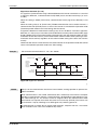
*2 When using terminals PC-SD as a 24V DC power supply,
take care not to short across terminals PC-SD.
Frequency setting signal (analog)
*3 Terminal input specifications
can be changed by analog
Frequency
input specifications
setting
switchover (Pr. 73) (initial
potentiometer
settings in frame). Terminal
1kΩ, 1/2W
10 and terminal 2 are used as
*4
PTC input terminal (Pr. 561).
*4 It is recommended to use
1kΩ/2W when the
frequency setting signal is
changed frequently.
10(+5V)
3
2
*3
)
5( Analog common )
1
Terminal 4
(+)
input
(Current input) (-)
*5 Terminal input specifications can be changed by analog
input specifications switchover (Pr. 267) (initial settings in
frame).
Set the voltage/current input switch in the "V" position to
select voltage input (0 to 5 V/0 to 10 V) and "I" to select
current input (0/4 to 20 mA.)
To use terminal 4 (initial setting is current input), set "4" in
any of Pr.178 to Pr.182 to assign the function.
Safety stop signal
2 0–5V DC
(0–10V DC
Shorting wire
(+)
5
(-)
Analog signal output
(0–10V DC)
PU
connector
4 4–20 mA DC
0–5V DC
0–10V DC
V
*5
I
Voltage/current
input switch
*5
Safe stop input (Channel 1)
S1
Safe stop input (Channel 2)
S2
Safe stop input common
AM
Terminal functions vary by Pr. 197
Output shutoff
circuit
SC
SO
Safety monitor output
*9
*9 Common terminal of terminal SO is terminal SC.
(Connected to terminal SD inside of the inverter.)
I002073E
Fig. 3-3: Terminal connection diagram of the inverter
3-4
Wiring
NOTES
Terminal connection diagramm
To prevent a malfunction due to noise, keep the signal cables more than 10cm away from
the power cables. Also separate the main circuit wire of the input side and the output side.
After wiring, wire offcuts must not be left in the inverter. Wire offcuts can cause an alarm,
failure or malfunction. Always keep the inverter clean. When drilling mounting holes in an
enclosure etc., take care not to allow chips and other foreign matter to enter the inverter.
The output of the single-phase power input specification is three-phase 230V.
FR-D700 EC
3-5
Main circuit connection
Wiring
3.3
Main circuit connection
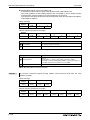
3.3.1
Specification of main circuit terminal
Terminal
Name
Description
R/L1,
S/L2,
T/L3 AC power input
Connect to the commercial power supply.
Keep these terminals open when using the high power factor converter
(FR-HC) or power regeneration common converter (FR-CV).
U, V, W
Inverter output
Voltage ouput of the inverter
(3~, 0V–power supply voltage, 0.2–400Hz)
+, PR
Brake resistor
connection
Connect a brake transistor (FR-ABR, MRS) across terminals + and PR.
(The brake resistor can not be connected to the FR-D720S-008 and 014.)
+, − Brake unit connection Connect the brake unit (FR-BU2), power regeneration common converter
(FR-CV) or high power factor converter (FR-HC) across terminals + and –.
+, P1
DC reactor
connection
Remove the jumper across terminals + and P1 and connect a DC reactor.
PE
For earthing the inverter chassis. Must be earthed.
Tab. 3-2: Specification of main circuit terminal
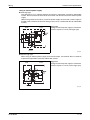
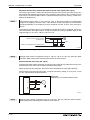
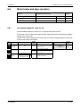
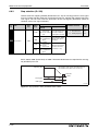
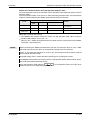
3.3.2
When using single-phase power input, terminals are L1 and N.
When using three-phase power input, terminals are P/+ and N/–.
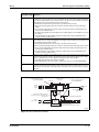
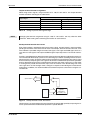
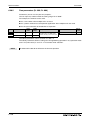
Terminal layout and wiring
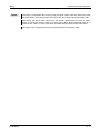
Single-phase, 200V class
FR-D720S-008 to 042
FR-D720S-070 and 100
Jumper
Jumper
Screw size (M3,5)
Screw size (M4)
Screw size
(M3,5)
M
3~
L1 N
L1N
Power supply
Power supply
M
3~
Motor
Motor
I002032E
Tab. 3-3: Terminal layout and wiring
3-6
Screw size
(M4)
I002033E
Wiring
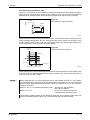
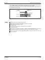
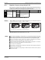
Main circuit connection
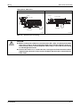
Three-phase, 400V class
FR-D740-012 to 080
FR-D740-120 and 160
Jumper
Jumper
Screw size (M4)
Screw size (M4)
Screw size (M4)
Screw size (M4)
M
3~
L1L2 L3
Power supply
L1L2 L3
Power supply
M
3~
Motor
Motor
I002034E
I002035E
Tab. 3-4: Terminal layout and wiring
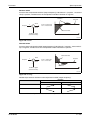
E
CAUTION:
● Make sure the power cables are connected to the R/L1, S/L2, T/L3 (three-phase 400V
class) resp. to the L1, N (for single-phase 200V class). (Phase sequence needs not
to be matched.) Never connect the power cable to the U, V, W of the inverter. Doing
so will damage the inverter.
● Connect the motor to U, V, W. At this time, turning on the forward rotation switch
(signal) rotates the motor in the counter clockwise direction when viewed from the
motor shaft.
FR-D700 EC
3-7
Main circuit connection
Wiring
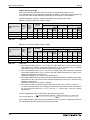
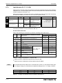
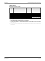
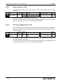
Cables and wiring length
Select the recommended cable size to ensure that a voltage drop will be 2% max.
If the wiring distance is long between the inverter and motor, a main circuit cable voltage drop
will cause the motor torque to decrease especially at the output of a low frequency.
The following tables indicate a selection example for the wiring length of 20m.
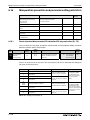
200V class (when input power supply is 220V)
Crimping
Terminal
Terminal
Screw
Size Tightening
Torque
[Nm]
M3,5
1,2
FR-D720S-070
M4
1,5
2-4
FR-D720S-100
M4
1,5
5,5-4
Applicable Inverter
Type
FR-D720S-008 to 042
Tab. 3-5:
Cable Size
HIV etc. [mm²] AWG PVC [mm²] L1, N,
P1, +
U, V, W
L1, N,
P1, +
U, V, W
Earth
cable
gauge
L1, N,
P1, +
U, V, W
L1, N,
P1, +
U, V, W
Earth
cable
gauge
2-3,5
2-3,5
2
2
2
14
14
2,5
2,5
2,5
2-4
2
2
2
14
14
2,5
2,5
2,5
2-4
3,5
2
3,5
12
14
4
2,5
4
Cable size
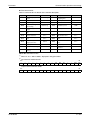
400V class (when input power supply is 440V)
Applicable Inverter
Type
Cable Size
Crimping
TightenTerminal
Terminal
HIV etc. [mm²]
AWG PVC [mm²] ing
Screw
Torque L1, L2,
L1, L2,
Earth L1, L2,
L1, L2,
Earth
Size [Nm]
L3, P1, U, V, W L3, P1, U, V, W cable L3, P1, U, V, W L3, P1, U, V, W cable
+
+
gauge
+
+
gauge
FR-D740-012 to 080
M4
1,5
2-4
2-4
2
2
2
14
14
2,5
2,5
2,5
FR-D740-120
M4
1,5
5,5-4
2-4
3,5
2
3,5
12
14
4
2,5
4
FR-D740-160
M4
1,5
5,5-4
5,5-4
3,5
3,5
3,5
12
12
4
4
4
Tab. 3-6:
Cable size
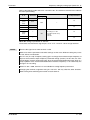
The recommended cable size is that of the HIV cable (600V class 2 vinyl-insulated cable)
with continuous maximum permissible temperature of 75°C. Assumes that the ambient
temperature is 50°C or less and the wiring distance is 20m or less.
The recommended cable size is that of the THHW cable with continuous maximum
permissible temperature of 75°C. Assumes that the ambient temperature is 40°C or less
and the wiring distance is 20m or less.
(Selection example for use mainly in the United States.)
The recommended cable size is that of the PVC cable with continuous maximum permissible
temperature of 70°C. Assumes that the ambient temperature is 40°C or less and the wiring
distance is 20m or less.
(Selection example for use mainly in Europe.)
The terminal screw size indicates the terminal size for R/L1, S/L2, T/L3, U, V, W, PR, +, –,
P1 and a screw for earthing. (For single-phase power input, the terminal screw size indicates
the size of terminal screw for L1, N, U, V, W, PR, +, – and P1 and a screw for earthing
(grounding).)
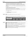
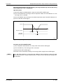
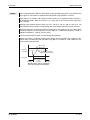
The line voltage drop can be calculated by the following expression:
3 × wire restistance [mΩ/m ] × wiring distance [m] × current [A]
Line voltage drop [V] = ------------------------------------------------------------------------------------------------------------------------------------------------------------------------1000
Use a larger diameter cable when the wiring distance is long or when it is desired to decrease
the voltage drop (torque reduction) in the low speed range.
3-8
Wiring
E
Main circuit connection
CAUTION:
● Tighten the terminal screw to the specified torque. A screw that has been tightened
too loosely can cause a short circuit or malfunction. A screw that has been
tightened too tightly can cause a short circuit or malfunction due to the unit
breakage.
● Use crimping terminals with insulation sleeve to wire the power supply and motor.
FR-D700 EC
3-9
Main circuit connection
Wiring
Notes on earthing
P
CAUTION:
Leakage currents flow in the inverter or the EMC filter respectively. To prevent an
electric shock, the inverter, input filter and motor must be earthed. This inverter must
be earthed. Earthing must conform to the requirements of national and local safety
regulations and electrical codes (JIS, NEC section 250, IEC 536 class 1 and other
applicable standards).
Use the dedicated earth terminal to earth the inverter. Do not use the screw in the casing, chassis, etc.
Use the thickest possible earth cable. Use the cable whose size is equal to or greater than that
indicated in Tab. 3-6, and minimize the cable length. The earthing point should be as near as
possible to the inverter.
Always earth the motor and inverter
● Purpose of earthing
Generally, an electrical apparatus has an earth terminal, which must be connected to the
ground before use.
An electrical circuit is usually insulated by an insulating material and encased. However, it
is impossible to manufacture an insulating material that can shut off a leakage current
completely, and actually, a slight current flow into the case. The purpose of earthing the case
of an electrical apparatus is to prevent operator from getting an electric shock from this
leakage current when touching it.
To avoid the influence of external noises, this earthing is important to audio equipment,
sensors, computers and other apparatuses that handle low-level signals or operate very fast.
● Earthing methods and earthing work
As described previously, earthing is roughly classified into an electrical shock prevention
type and a noise affected malfunction prevention type. Therefore, these two types should
be discriminated clearly, and the following work must be done to prevent the leakage current
having the inverter's high frequency components from entering the malfunction prevention
type earthing:
– Where possible, use independent earthing for the inverter. If independent earthing (I) is
impossible, use joint earthing (II) where the inverter is connected with the other equipment at an earthing point. Joint earthing as in (III) must be avoided as the inverter is
connected with the other equipment by a common earth cable.
Also a leakage current including many high frequency components flows in the earth
cables of the inverter and inverter-driven motor. Therefore, they must use the independent earthing method and be separated from the earthing of equipment sensitive to the
aforementioned noises.
In a tall building, it will be a good policy to use the noise malfunction prevention type
earthing with steel frames and carry out electric shock prevention type earthing in the
independent earthing method.
– This inverter must be earthed. Earthing must conform to the requirements of national
and local safety regulations and electrical codes. (JIS, NEC section 250, IEC 536 class
1 and other applicable standards).
– Use the thickest possible earth cable. The earth cable should be of not less than the size
indicated in Tab. 3-6.
– The grounding point should be as near as possible to the inverter, and the ground wire
length should be as short as possible.
– Run the earth cable as far away as possible from the I/O wiring of equipment sensitive
to noises and run them in parallel in the minimum distance.
Inverter
Other
equipment
(I) Independent earthing
(best solution)
Inverter
Other
equipment
(II) Common earthing
(good solution)
Inverter
Other
equipment
(III) Common earthing
(not allowed)
I001016E
Fig. 3-4: Earthing the drive
3 - 10
Wiring
Main circuit connection
Total wiring length
The maximum possible length of the motor cables depends on the capacity of the inverter and
the selected carrier frequency.
The lengths in the following tables are for unshielded cables. When shielded cables are use divide the values listed in the table by 2.
200V class
Pr. 72 "PWM frequency
selection" setting
(carrier frequency)
FR-D720S008
014
025
042
≥ 070
≤ 1 (1kHz)
200 m
200 m
300 m
500 m
500 m
2 to 15 (2kHz to 14,5kHz)
30 m
100 m
200 m
300 m
500 m
Tab. 3-7: Total wiring length
400V class
Pr. 72 "PWM frequency
selection" setting
(carrier frequency)
FR-D740012
022
036
050
≥ 080
≤ 1 (1kHz)
200 m
200 m
300 m
500 m
500 m
2 to 15 (2kHz to 14,5kHz)
30 m
100 m
200 m
300 m
500 m
Tab. 3-8: Total wiring length
≤ 500m
Fig. 3-5:
Remember that in the table above the total
wiring length is what is being referred to. In
parallel connections of several motors every
motor wire must be counted. In this example,
for the inverter FR-D720S-070 or more or
FR-D740-080 or more the permissible wiring
length is exceeded by the two parallel motor
lead wires.
300m
300m
300m + 300m = 600m
FR-D700 EC
I001980E
3 - 11
Main circuit connection
NOTES
Wiring
Note that the motor windings are subjected to significantly higher loads when the motor is
operated by inverter than with normal mains operation. The motors must be approved for
inverter operation by the manufacturer (refer also to section 3.7.4).
Especially for long-distance wiring, the inverter may be affected by a charging current
caused by the stray capacitances of the wiring, leading to a malfunction of the overcurrent
protective function, fast response current limit function, or stall prevention function or a malfunction or fault of the equipment connected on the inverter output side.
If fast-response current limit malfunctions, disable this function. When the stall prevention
function misoperates, increase the stall level. (Refer Pr. 22 "Stall prevention operation level"
and Pr. 156 "Stall prevention operation selection".)
Refer to section 6.14.1 for details of Pr. 72 "PWM frequency selection".
When using the automatic restart after instantaneous power failure function with wiring
length exceeding below, select without frequency search (Pr. 162 = "1, 11").
3 - 12
Motor capacity
0.1K
0.2K
≥ 0.4K
Wiring length
20 m
50 m
100 m
Wiring
3.4
Control circuit specifications
Control circuit specifications
The functions of the terminals highlighted in grey can be adjusted with parameters 178 to 182
"Input terminal function assignment" and Pr. 190, Pr. 192 or Pr. 197 "Output terminal function assignment" (refer to section 6.9). The listed settings show the default configuration as shipped,
which you can restore by resetting to the factory defaults.
Input signals
Contact input
Terminal
Rated
Refer to
page
Specifications
Name
Description
STF
Forward rotation
start
Turn on the STF signal to
start forward rotation and
turn it off to stop.
STR
Reverse rotation
start
Turn on the STR signal to
start reverse rotation and
turn it off to stop.
Multi-speed
selection
Multi-speed can be selected according to the
combination of RH, RM and RL signals.
Contact input
common (sink)
24V DC power
supply common
A determined control function is activated, if
the corresponding terminal is connected to the
terminal SD (sink logic). The SD terminal is
isolated from the digital circuits via optocouplers.
The terminal is isolated from the reference
potential of the analog circuit (terminal 5).
—
24V DC
power supply,
contact input
common (source)
24V DC/0.1A output
With negative logic and control via open collector transistors (e.g. a PLC) the positive pole
of an external power source must be connected to the PC terminal. With positive logic
the PC terminal is used as a common reference for the control inputs. This means that
when positive logic is selected (default setting
of the EC units) the corresponding control
function is activated by connecting its terminal
to the PC terminal.
Power supply
voltage range:
22V to
26,5V DC
Permissible
load current:
100 mA
RH, RM, RL
Reference point
SD
PC
When the STF
and STR signals
are turned on
simultaneously,
the stop command is given.
Input resistance: 4.7kΩ
Voltage at
opening:
21V to 26V DC
Contacts at
short-circuited:
4 to 6mA DC
6-88
—
3-25
Tab. 3-9: Input signals (1)
FR-D700 EC
3 - 13
Control circuit specifications
Terminal
10
(Output
voltage
5V DC)
Frequency setting
2
4
Wiring
Name
Description
Rated
Refer to
Specifications
Frequency setting
power supply
Used as power supply when connecting potentiometer for frequency setting (speed setting)
from outside of the inverter.
Rated output voltage: 5V DC
Recommended potentiometer: 1kΩ, 2W linear,
multi turn potentiometer
5.0V DC ± 0,2V,
Permissible
load current
10mA
Frequency setting
(voltage)
Inputting 0 to 5V DC (or 0 to 10V) provides the
maximum output frequency at 5V (10V) and
makes input and output proportional. Use
Pr. 73 to switch from among input 0 to 5V DC
(initial setting), 0 to 10V DC.
Input resistance:
10kΩ ± 1kΩ
Maximum
permissible
voltage:
20V DC
Frequency setting
(current)
Inputting 4 to 20mA DC (or 0 to 5V, 0 to 10V)
provides the maximum output frequency at
20mA and makes input and output proportional. This input signal is valid only when the
AU signal is on (terminal 2 input is invalid).
To use terminal 4 (initial setting is current
input), set "4" in any of Pr.178 to Pr.182 to
assign the function, and turn ON AU signal.
Use Pr. 267 to switch from among input 4 to
20mA (initial setting), 0 to 5V DC and 0 to
10V DC. Set the voltage/current input switch in
the "V" position to select voltage input (0 to 5V/
0 to 10V).
Current input
(initial status)
PTC thermistor
5
6-147
Voltage input:
Input resistance:
10kΩ ± 1kΩ
Maximum
permissible
voltage:
20V DC
Frequency setting
common
Terminal 5 provides the common reference
potential (0V) for all analog set point values
and for the analog output signals AM (voltage).
The terminal is isolated from the digital circuit’s
reference potential (SD). This terminal should
—
not be grounded. If local regulations require
grounding of the reference potential note that
this can propagate any noise in the ground
potential to the control electronics, thus
increasing sensitivity to interference.
PTC thermistor
input
For connecting PTC thermistor output (thermal
motor protection).
When PTC thermistor protection is valid
(Pr. 561 ≠ 9999) terminal 2 is not available for
frequency setting.
10
2
Voltage input
Current input:
Input resistance:
233Ω ± 5Ω
Maximum
permissible
current: 30mA
PTC thermistor resistance:
500Ω–30kΩ
(Set by Pr. 561)
6-66
Tab. 3-9: Input signals (2)
NOTE
3 - 14
Set Pr. 267 and a voltage/current input switch correctly, then input analog signals in accordance with the settings.
Applying a voltage with voltage/current input switch in "I" position (current input is selected)
or a current with switch in"V" position (voltage input is selected) could cause component
damage of the inverter or analog circuit of output devices. Refer to section 6.15 for details.
Wiring
Control circuit specifications
Output signals
Relay
Terminal
A, B, C
Rated
Refer to
Specifications
Name
Description
Relay output
(alarm output)
The alarm is output via relay contacts. The
block diagram shows the normal operation and
voltage free status. If the protective function is
activated, the relay picks up.
B
A
Contact
capacity:
230V AC/0.3A
(Power
factor: 0.4) or
30V DC/0.3A
C
Analog output
Open collector
6-98
Permissible
load:
24V DC (max.
27V DC), 0.1A
(A voltage drop
is 3.4V maximum when the
signal is on.)
RUN
Inverter running
Switched low when the inverter output frequency is equal to or higher than the starting
frequency (initial value 0.5Hz).
Switched high during stop or DC injection
brake operation.
SE
Open collector
output common
Reference potential for the signal RUN. This
terminal is isolated from the reference potential of the control circuit SD.
—
Analog voltage
output
Select one e.g. output frequency (Pr. 158) from 18
monitor items.
The output signal is proportional to the magnitude of
the corresponding monitoring item.
Not output during inverter
reset.
Output signal:
0–10V DC
Permissible
load current:
1 mA
(load impedance:
≥ 10kΩ)
Resolution:
8 bit
AM
Output item:
Output
frequency
(initial setting)
—
6-118
Tab. 3-10: Output signals
Communication
RS485
Name
PU connector
Description
Specification
With the PU connector, communication can be
made through RS485.
Conforming standard:
EIA-485 (RS485)
Transmission format:
Multidrop
Communication speed:
4800 to 38400bps
Overall length: 500m
Refer to
3-28,
6-193
Tab. 3-11: Communication signal
FR-D700 EC
3 - 15
Control circuit specifications
Wiring
Safety stop signal
Terminal
Name
Description
Specification
S1
Safe stop input
(Channel 1)
Terminals S1 and S2 are for safety stop
input signals used with the safety relay
module. Terminals S1 and S2 are used
simultaneously (dual channel). Inverter
output is shut off by shortening/opening
across terminals S1 and SC and across
S2 and SC. In the initial status, terminals
S1 and S2 are shorted with terminal SC by
shortening wire. Remove the shortening
wire and connect the safety relay module
when using the safety stop function.
Input resistance:
4.7kΩ (In case of
shorted to SC)
Voltage:
21V to 26V (In case of
open from SC)
Load:
24VDC/0.1A max.
Voltage drop:
3.4V max.
(In case of 'ON' state)
S2
Safe stop input
(Channel 2)
SO
Safety monitor output
(open collector output)
The signal indicates the status of safety
stop input. Low indicates safe state, and
High indicates drive enabled or fault detected. (Low is when the open collector output transistor is ON (conducts). High is
when the transistor is OFF (does not conduct).)
If High is output when both of terminals S1
and S2 are open, refer to the "Transistorized Inverter FR-D700 Safety Stop Instructional Manual, document no.:
BCN-A211508-000“ for the cause and
countermeasure.
SC
Safe stop input
terminal common
Common terminal for terminals S1, S2 and
SO.
—
Connected to terminal SD inside of the
inverter.
Tab. 3-12: Safety stop signal
3 - 16
Refer to
page
3-21
Wiring
3.4.1
Control circuit specifications
Control circuit terminals
Recommended cable size:
0.3 mm² to 0.75 mm²
10
2
5
4 AM
RUN SE SO S1 S2 SC SD
A
B
C
RL RM RH SD PC STF STR
I001982E
Fig. 3-6: Terminal layout
Connection to the terminals
Use a wire end sleeve and a cable with a sheath stripped off for the control circuit wiring. For a
single wire, strip off the sheath of the cable and apply directly.
Remove about 10mm of the cable insulation. Wire the stripped cable after twisting it to
prevent it from becoming loose. In addition, do not solder it.
Fig. 3-7:
Preparation of the cable
10mm
I001326E
Insert wires to a wire end sleeve, and check that the wires come out for about 0 to 0.5 mm
from a sleeve.
Fig. 3-8:
Fixing of wire end sleeves
Cable
Sleeve
Shell
0–
mm
0,5
I001984E
Check the condition of the wire end sleeve after crimping. Do not use a wire end sleeve of
which the crimping is inappropriate, or the face is damaged.
Unstranded wires
Damaged
Crumpled tip
Wires are not inserted
into the shell
I001985E
Fig. 3-9: Incorrectly crimped wire end sleeves
FR-D700 EC
3 - 17
Control circuit specifications
Wiring
Wire end sleeve Model
Wire Size [mm²]
With Insulation Sleeve
Without Insulation
Sleeve
0.3/0.5
Al 0.5-10WH
—
0.75
Al 0.75-10GY
A 0.75-10
1
Al 1-10RD
A 1-10
1.25/1.5
Al 1.5-10BK
A 1.5-10
0.75 (for two wires)
Al-TWIN 2 × 0.75-10GY
—
Recommended wire end
sleeve crimping tool
CRIMPFOX ZA3
(Maker: Phoenix
Contact Co., Ltd)
Tab. 3-13: Recommended wire end sleeves (Maker: Phoenix Contact Co., Ltd)
Wire Size [mm²]
Wire end sleeve
product number
Insulation
product number
0.3 to 0.75
BT 0.75-11
VC 0.75
Recommended wire end
sleeve crimping tool
NH 67
Tab. 3-14: Recommended wire end sleeves (Maker: NICHIFU Co., Ltd)
Insert the wire into a socket.
Fig. 3-10:
Cable connection
I001986E
When using a stranded wire without a wire end sleeve or a single wire, push a open/close
button all the way down with a flathead screw driver, and insert the wire.
Open/close button
Fig. 3-11:
Connection of a stranded wire
Flathead
screwdriver
I001987E
E
3 - 18
CAUTION:
● When using a stranded wire without a wire end sleeve, twist enough to avoid short
circuit with a nearby terminals or wires.
● Place the flathead screwdriver vertical to the open/close button. In case the blade
tip slips, it may cause to damage of inverter or injuries.
Wiring
Control circuit specifications
Wire removal
Pull the wire with pushing the open/close button all the way down firmly with a flathead screwdriver.
Open/close button
Fig. 3-12:
Wire removal
Flathead
screwdriver
I001988E
E
CAUTION:
● Use a small flathead screwdriver (Tip thickness: 0.4mm/tip width: 2.5mm, such as
SFZ 0-0,4 x 2,5 of Phoenix Contact Co., Ltd.). If a flathead screwdriver with a narrow
tip is used, terminal block may be damaged.
● Place the flathead screwdriver vertical to the open/close button. In case the blade
tip slips, it may cause to damage of inverter or injuries.
Common terminals of the control circuits PC, 5, SE
Terminals PC, 5, and SE are all common terminals (0V) for I/O signals and are isolated from
each other. Avoid connecting the terminal PC and 5 and the terminal SE and 5. Terminal PC is
a common terminal for the contact input terminals (STF, STR, RH, RM and RL).
The open collector circuit is isolated from the internal control circuit by photocoupler.
Terminal 5 is a common terminal for frequency setting signal (terminal 2 or 4) and analog output
terminal AM. It should be protected from external noise using a shielded or twisted cable.
Terminal SE is a common terminal for the open collector output terminal RUN.
The contact input circuit is isolated from the internal control circuit by photocoupler.
Signal inputs by contactless switch
The contacted input terminals of the inverter (STF, STR, RH, RM and RL) can be controlled using a transistor instead of a contacted switch as shown below. According to the adjusted control
logic, PNP transistors (positive logic) or NPN transistors (negative logic) must be used to activate the inputs.
Inverter
PC
Fig. 3-13:
External signal input in source logic using
transistor (initial setting)
STF, etc.
I001020E
FR-D700 EC
3 - 19
Control circuit specifications
3.4.2
Wiring
Wiring instructions
● Use shielded or twisted cables for connection to the control circuit terminals and run them
away from the main and power circuits (including the 200V relay sequence circuit).
● Use two or more parallel micro-signal contacts or twin contacts to prevent a contact faults
when using contact inputs since the control circuit input signals are micro-currents.
Fig. 3-14:
Contacts
Micro signal contacts
Twin contacts
I001021E
● Do not apply a voltage to the contact input terminals (e.g. STF) of the control circuit.
● Always apply a voltage to the alarm output terminals (A, B, C) via a relay coil, lamp, etc. In
no way must a voltage be short-circuited by these relay contacts.
● It is recommended to use the cables of 0.75mm² gauge for connection to the control circuit
terminals. If the cable gauge used is 1,25 mm² or more, the front cover may not be mounted
correctly. Run the cables in a proper way in order to mount the front cover correctly.
● The wiring length should be 30m maximum.
● Do not short terminal PC and SD. Inverter may be damaged.
3 - 20
Wiring
3.4.3
Control circuit specifications
Safety stop function
The terminals related to the safety stop function are shown below. For the rated specification of
each terminal refer to Tab. 3-12.
Terminal
S1
S2
SO Description
For input of safety stop channel 1.
For input of safety stop channel 2.
SAFE
signal
SC
RUN SE
SAFE2
signal
Between S1 and SC / S2 and SC
Open: In safety stop mode.
Short: Other than safety stop mode.
For output of safety stop condition.
The signal is output when inverter output is shut
off due to the safety stop function.
OFF: Drive enabled
ON: Output shutoff, no fault
Common terminal for S1,S2,SO signals.
SC is connected terminal SD internally.
—
As output for failure detection and alarm.
The signal is output while safety circuit fault
(E.SAF) is not activated.
OFF: Safety circuit fault (E.SAF)
ON: Status other than Safety circuit fault
(E.SAF)
Common terminal for open collector outputs (terminal RUN)
—
Tab. 3-15: Safety stop function terminals
In the initial status, terminal S1 and S2 are shorted with terminal SC by shortening wire.
Remove the shortening wire and connect the safety relay module when using the safety
stop function.
In the initial setting, safety monitor output signal (SAFE signal) is assigned to terminal SO.
The function can be assigned to other terminals by setting "80" (positive logic) or "180"
(negative logic) to any of Pr. 190, Pr. 192 or Pr. 197.
In the initial setting, inverter running (RUN signal) is assigned to terminal RUN. Set "81" to
Pr. 190 to assign SAFE2 signal. The function can be assigned to other terminals by setting
"81" (positive logic) or "181" (negative logic) to any of Pr. 190, Pr. 192 or Pr. 197.
NOTES
Use SAFE signal for the purpose to monitor safety stop status. SAFE signal cannot be used
as safety stop input signal to other devices (other than the safety relay module.)
SAFE2 signal can only be used to output an alarm or to prevent restart of an inverter. The
signal cannot be used as safety stop input signal to other devices.
FR-D700 EC
3 - 21
Control circuit specifications
Wiring
Wiring connection diagram
To prevent restart at fault occurrence, connect terminals RUN (SAFE2 signal) and SE to terminals XS0 and XS1, which are the feedback input terminals of the safety relay module.
By setting Pr.190 to "81" (SAFE2 signal), terminal RUN is turned OFF at fault occurrence.
Pr. 178 = 60 (initial value)
Pr. 179 = 25
Pr. 190 = 81
Pr. 197 = 80 (initial value)
R S T
Inverter
SO (SAFE) monitor
RUN (SAFE2) START/RESET
SE
STF I/O control
STR (STOP) EM
S1
STOP
Output shutoff
circuit
S2
+24V
X0 COM0 X1 COM1
XS0 XS1
SC
Z00 Z10 Z20
PC
Internal Safety
Circuit
24V DC
K1
U VW
K2
M
3~
24G
Z01 Z11 Z21
Safety relay module
QS90SR2SN-Q
Output signals differ by the setting of Pr. 190, Pr. 192
and Pr. 197.
Input signals differ by the setting of Pr. 178 to Pr. 182.
I002074E
Fig. 3-15: Connecting the Safety relay module QS90SR2SN-Q of Mitsubishi
NOTE
Changing the terminal assignment using Pr. 190, Pr. 192 or Pr. 197 may affect the other
functions. Make setting after confirming the function of each terminal.
Safety stop function operation
Input power
S1-SC
S2-SC
Failure
(E.SAF)
SAFE SAFE2 Operation state
OFF
—
—
—
OFF
OFF
Output shutoff (Safe state)
No failure
OFF
ON
Drive enabled
Short
Short
Detected
OFF
OFF
Output shutoff (Safe state)
ON
Open
No failure
ON
ON
Output shutoff (Safe state)
Detected
OFF
OFF
Output shutoff (Safe state)
Open
Short
Open
Detected
OFF
OFF
Output shutoff (Safe state)
Open
Short
Detected
OFF
OFF
Output shutoff (Safe state)
Tab. 3-16: Description of Safety stop function operation
3 - 22
ON: Transistor used for an open collector output is conducted.
OFF: Transistor used for an open collector output is not conducted.
Wiring
Control circuit specifications
Instruction on product safety when using the "Safety stop" function
P
WARNING:
The drawing on page 6 in the English manual "Safety stop function instruction manual
for FR-D700 Transistorized Inverter (BCN-A211508-000-C)" contains an error that
might result in an unsafe state when using the function "Safety stop torque". This risk
exists when several FR-D700 inverters are connected in parallel to a safety relay.
The following product saftey notices explain the potential safety issue and the steps
being taken to rectify the situation.
If your inverter is operated in the configuration described here, or in a similar
configuration, then the remedial measures listed here must be carried out immediately!
Issue
The drawing on page 6 of the manual BCN-A211508-000-C does not show diodes which must
be placed on the inputs S1 and S2. Without these diodes in place, when the user installs a configuration which has multiple FR-D700 inverters with their Safe Torque Off inputs (S1 and S2)
wired in parallel to a single safety relay with one or more of the connected inverters powered off,
then in this condition there is a strong potential that the Safe Torque Off function will not activate
when required on the inverters that remain powered.
Safety relay module
Missing diodes
I002075E
Fig. 3-16: Error in circuit diagram
FR-D700 EC
3 - 23
Control circuit specifications
Wiring
Corrective/remedial action
● Immediate action:
– Ensure that all inverters are powered up when operating machinery with FR-D700
inverters that have their Safe Torque Off Function wired/installed in the described
configuration.
– Download revised manual BCN-A211508-000-D Safety stop function instruction manual
for FR-D700 from your local Mitsubishi website (www.mitsubishi-automation.com).
● Issue correction:
At your earliest convenience please halt the operation of your machinery and get a qualified
electrician to insert one diode, of the following specification, inline as shown on the following
diagram.
Diode specifications:
Vr (peak reverse voltage): 50V or more
If (forward current): 100 mA or more
Vf (foward voltage) @ 5mA: 1V or less
Type of diode : PN junction type
A Schottky barrier diode is not appropriate for this application as its reverse leakage current
is large.
Safety relay module
Diodes shown
correctly in place
I002076E
Fig. 3-17: Issue correction
NOTE
3 - 24
If you are unsure if you have this style of installation please contact your local Mitsubishi
Electric Factory Automation representative.
Wiring
3.4.4
Control circuit specifications
Changing the control logic
FR-D700 frequency inverters offer the possibility of choosing between two types of control logic.
Depending on the direction of the flowing current, one distinguishes between:
● In sink logic, a signal switches on when a current flows from the corresponding signal input
terminal. Terminal SD is common to the contact input signals. Terminal SE is common to
the open collector output signals.
● In source logic, a signal switches on when a current flows into the corresponding signal input
terminal. Terminal PC is common to the contact input signals. Terminal SE is common to
the open collector output signals.
Current flow concerning the input/output
signals when sink logic is selected
Current flow concerning the input/output
signals when source logic is selected
current
SINK
current
SOURCE
FR-D700
DC input (sink type)
AX40
RUN
Current
FR-D700
DC input (source type)
AX80
RUN
Current
I001029E
Fig. 3-18: Changing the control logic
The input signals are set to source logic (SOURCE) when shipped from the factory. To change
the control logic, the jumper connector above the control circuit terminal block must be moved
to the other position.
(The output signals may be used in either the sink or source logic independently of the jumper
connector position.)
Fig. 3-19:
Changing the control logic
I001989E
FR-D700 EC
3 - 25
Control circuit specifications
NOTES
Wiring
Turn off the inverter power before switching a jumper connector.
The sink-source logic change-over jumper connector must be fitted in only one of those
positions. If it is fitted in both positions at the same time, the inverter may be damaged.
The capacity plate is placed on the front cover and the rating plate is on the inverter. Since
these plates have the same serial numbers, always reinstall the removed cover onto the original inverter.
3 - 26
Wiring
Control circuit specifications
Using an external power supply
● Sink logic type
Use terminal PC as a common terminal to prevent a malfunction caused by undesirable
current. Do not connect terminal SD of the inverter with terminal 0V of the external power
supply.
(When using terminals PC-SD as a 24V DC power supply, do not install a power supply in
parallel in the outside of the inverter. Doing so may cause a malfunction due to undesirable
current.)
QY40
Inverter
Fig. 3-20:
Using an external power supply in connection
with the outputs of a PLC (sink logic type)
Current
I001030E
● Source logic type
When using an external power supply for transistor output, use terminal SD as a common
to prevent misoperation caused by undesirable current.
AY80
Inverter
Fig. 3-21:
Using an external power supply in connection
with the outputs of a PLC (source logic type)
Current
I001031E
FR-D700 EC
3 - 27
PU connector
3.5
Wiring
PU connector
Using the PU connector, you can perform communication operation from a parameter unit
FR-PU07/FR-PA07 or a personal computer. Parameter setting and monitoring can be performed by FR Configurator.
Remove the inverter front cover when connecting.
Fig. 3-22:
PU connector
I001990E
3.5.1
Connecting the parameter unit
A FR-PU07/FR-PA07 parameter unit can be connected via the FR-A5CBL line to the inverter
and, e.g. then mounted onto a control cabinet to control the inverter from there. The maximum
line length must not exceed 20m.
When connecting, make sure that the plugs in the inverter and in the parameter unit are correctly
engaged. Install the inverter front cover after connecting.
Cable FR-A5CBL (option)
PU connector
FR-PA07
FR-PU07
I001991
Fig. 3-23: Connecting a parameter unit using a connection cable
3 - 28
Wiring
3.5.2
PU connector
RS485 communication
When the PU connector is connected with a personal, FA or other computer by a communication
cable, a user program can run and monitor the inverter or read and write to parameters.
The protocol can be selected from Mitsubishi inverter and Modbus RTU. For detailed information refer to section 6.18.
Specification
Description
Conforming standard:
EIA-485 (RS485)
Transmission form
Multidrop link
Communication speed
4800 to 38400 Baud
Overall extension
500m
Tab. 3-17: Technical data of communication interface
FR-D700 EC
3 - 29
Connection of stand-alone option units
3.6
Wiring
Connection of stand-alone option units
The inverter accepts a variety of stand-alone option units as required.
E
3.6.1
CAUTION:
Incorrect connection will cause inverter damage or accident. Connect and operate the
option unit carefully in accordance with the corresponding option unit manual.
Magnetic contactors (MC)
Inverter input side magnetic contactor (MC)
On the inverter input side, it is recommended to provide an MC for the following purposes.
● To release the inverter from the power supply when the fault occurs or when the drive is not
functioning (e.g. emergency stop operation).
When cycle operation or heavy-duty operation is performed with an optional brake resistor
connected, overheat and burnout of the discharging resistor can be prevented if a regenerative brake transistor is damaged due to insufficient heat capacity of the discharging resistor
and excess regenerative brake duty.
● To prevent any accident due to an automatic restart at restoration of power after an inverter
stop made by a power failure.
● The control power supply for inverter is always running and consumes a little power. When
stopping the inverter for an extended period of time, powering off the inverter will save power
slightly.
● To separate the inverter from the power supply to ensure safe maintenance and inspection
work. The inverter's input side MC is used for the above purpose, select class JEM1038AC3MC for the inverter input side current when making an emergency stop during normal
operation.
NOTE
3 - 30
Since repeated inrush currents at power on will shorten the life of the converter circuit
(switching life is about 1,000,000 times.), frequent starts and stops of the MC must be
avoided. Turn on/off the inverter start controlling terminals (STF, STR) to run/stop the
inverter.
Wiring
Example 쑴
Connection of stand-alone option units
As shown below, always use the start signal (ON or OFF across terminals STF or STR-PC)
to make a start or stop. (Refer to section 6.9.4.)
Inverter
Power
supply
MCCB
MC
R/L1
S/L2
T/L3
U
V
W
To the
motor
T
C
B
Operation preparation
MC
OFF
ON
MC
MC
RA
A
STF(STR)
PC
Start/Stopp Operation
RA
Start
Stop
RA
I002080E
Fig. 3-24: Example for connection of an inverter
When the power supply is 400V class, install a step-down transformer.
쑶
Handling of the inverter output side magnetic contactor
Switch the magnetic contactor between the inverter and motor only when both the inverter and
motor are at a stop. When the magnetic contactor is turned on while the inverter is operating,
overcurrent protection of the inverter and such will activate. When an MC is provided for switching to the commercial power supply, for example, switch it on/off after the inverter and motor
have stopped.
FR-D700 EC
3 - 31
Connection of stand-alone option units
3.6.2
Wiring
Connection of a dedicated external brake resistor FR-ABR and MRS
(FR-D720S-025 or more, FR-D740-012 or more)
Install a dedicated brake resistor (FR-ABR or MRS) outside when the motor is made to run by
the load, quick deceleration is required, etc. Connect a dedicated brake resistor (FR-ABR or
MRS) to terminal + and PR. (For the locations of terminal + and PR, refer to the terminal block
layout (section 3.3.2).)
Set parameters below (refer to section 6.8.2).
Connected brake
resistor
Parameter setting
Pr. 30 „Regenerative
function selection“
Pr. 70 „Special regenerative brake duty“
0 (initial value)
—
1
10 (%)
MRS
FR-ABR
Tab. 3-18: Setting of parameter 30 and 70 when connecting an external brake resistor
E
CAUTION:
● The brake resistor connected should only be the dedicated brake resistor FR-ABR
or MRS.
● Do not remove a jumper across terminal + and P1 except when connecting a DC
reactor.
● The shape of jumper differs according to capacities.
FR-D720S-025 and 042
Jumper
Fig. 3-25:
Connection of a brake resistor to the terminals
+ and PR for the inverters FR-D720S-025 and
FR-D720S-042
Terminal +
Terminal PR
Brake resistor
3 - 32
I002036E
Wiring
Connection of stand-alone option units
FR-D720S-070 and 100 and FR-D740-012 to 080
Jumper
Fig. 3-26:
Connection of a brake resistor to the terminals
+ and PR for the inverters FR-D720S-070 and
100 and FR-D740-012 to FR-D740-080
Terminal +
Terminal PR
Brake resistor
I001923E
FR-D740-120 and 160
Jumper
Fig. 3-27:
Connection of a brake resistor to the terminals
+ and PR for the inverters FR-D740-120 and
FR-D740-160
Terminal +
Terminal PR
Brake resistor
I001924E
FR-D700 EC
3 - 33
Connection of stand-alone option units
Wiring
It is recommended to configure a sequence, which shuts off power in the input side of the inverter by the external thermal relay as shown below, to prevent overheat and burnout of the high
duty brake resistor in case the regenerative brake transistor is damaged. The following figure
shows two connection examples (circuits). (The brake resistor can not be connected to the
FR-D720S-008 or 014.)
Example 2
Example 1
Inverter
Thermo relay
(OCR) Inverter
Brake
restistor
Power
supply
Thermo relay
(OCR) Brake
restistor
Power
supply
T
T
ON OFF
ON OFF
OCR
contact
OCR
contact
I002043E
Fig. 3-28: Protection circuits
Refer to Tab. 3-19 for the type number of each capacity of thermal relay and the diagram for
the connection.
When the power supply is 400V class, install a step-down transformer.
Type
MRS
Power Supply
Voltage
FR-ABR
230V
400V
High-duty Brake
Resistor
Thermal Relay Type
(Mitsubishi Product)
MRS120W200
TH-N20CXHZKP-0.7A
MRS120W100
TH-N20CXHZKP-1.3A
MRS120W60
TH-N20CXHZKP-2.1A
MRS120W40
TH-N20CXHZKP-3.6A
FR-ABR-0.4K
TH-N20CXHZKP-0.7A
FR-ABR-0.75K
TH-N20CXHZKP-1.3A
FR-ABR-1.5K
TH-N20CXHZKP-2.1A
FR-ABR-H0.4K
TH-N20CXHZKP-0.24A
FR-ABR-H0.75K
TH-N20CXHZKP-0.35A
FR-ABR-H1.5K
TH-N20CXHZKP-0.9A
FR-ABR-H2.2K
TH-N20CXHZKP-1.3A
FR-ABR-H3.7K
TH-N20CXHZKP-2.1A
FR-ABR-H5.5K
TH-N20CXHZKP-2.5A
FR-ABR-H7.5K
TH-N20CXHZKP-3.6A
Contact Rating
110V AC/5A
220V AC/2A (AC 11 class),
110V DC/0.5A
220V DC/0.25A (DC 11 class)
Tab. 3-19: Resistor and thermal relay combination
Fig. 3-29:
Connecting the thermal relay
To the inverter
+ terminal
E
3 - 34
To a resistor
I001458E
CAUTION:
● Brake resistor can not be used with the brake unit (FR-BU2), high power factor
converter (FR-HC), power supply regeneration converter (FR-CV), etc.
● Do not connect a resistor directly to the DC terminals + and –. This could cause a
fire.
Wiring
3.6.3
Connection of stand-alone option units
Connection of a brake unit FR-BU2
When connecting a brake unit to improve the brake capability at deceleration, make connection
as shown below.
Connection example with the GRZG type discharging resistor
OFF
OFF
ON
ON
OCROCRcontact
contact
TT MC
MC
MCCB
MCCB
3-phase AC
AC
3-phase
power supply
supply
power
MC
MC
Inverter
Inverter
R/L1
R/L1
S/L2
S/L2
T/L3
T/L3
U
U
Motor
Motor
M
M
3~
3~
VV
W
W
++
--
5m ≤≤ 5m
MC
MC
GRZG type
type
GRZG
discharging resistor OCRdischarging resistor
OCR
External
External
thermal
thermal
relay
relay
R
R
R
R
FR-BU2
FR-BU2
PR
PR
AA
P/+
P/+
BB
N/N/BUE
BUE
C
C
SD
SD
I002077E
Fig. 3-30: Connection with the brake unit FR-BU2
If the control contacts are only specified for 230V control power you must install a transformer
when using a 400V power supply.
Connect the inverter terminals (+, −) and brake unit terminals so that their terminal signals
match with each other. (Incorrect connection will damage the inverter.)
The wiring distance between the inverter, brake unit and resistor unit should be within 5m.
If twisted wires are used, the distance should be within 10m.
If the transistors in the brake unit should become faulty, the resistor can be unusually hot,
causing a fire. Therefore, install a magnetic contactor on the inverters input side to configure
a circuit so that a current is shut off in case of fault.
Refer to FR-BU2 manual for connection method of discharging resistor.
Brake Unit
Discharging Resistor
External Thermal Relay
FR-BU2-1.5K
GZG 300W-50Ω (one)
TH-N20CXHZKP-1.3A
FR-BU2-7.5K
GRZG 200-10Ω (six in series)
TH-N20CXHZKP-3.6A
FR-BU2-15K
GRZG 300-5Ω (eight in series)
on request
Tab. 3-20: Recommended external relay
Fig. 3-31:
Connecting the thermal relay
To the brake unit
terminal P/+
FR-D700 EC
To a resistor
I001458E
3 - 35
Connection of stand-alone option units
E
Wiring
CAUTION:
● If the transistors in the brake unit should become faulty, the resistor can be
unusually hot, causing a fire.
Therefore, install a magnetic contactor on the inverters input side to configure a
circuit so that a current is shut off in case of fault.
● Do not remove a jumper across terminal + and P1 except when connecting a DC
reactor.
NOTE
3 - 36
Set "1" in Pr. 0 "Brake mode selection" of the FR-BU2 to use GRZG type discharging resistor.
Wiring
Connection of stand-alone option units
Connection example with the FR-BR(-H) type resistor
ON
OFF
T
MC
Inverter
Motor
3-phase AC
power supply
M
3~
≤ 5m 002045E
Fig. 3-32: Connection with the brake unit FR-BU2
E
If the control contacts are only specified for 230V control power you must install a transformer
when using a 400V power supply.
Normal: across TH1-TH2 ... close, Alarm: across TH1-TH2 ... open
Connect the inverter terminals (+, −) and brake unit terminals so that their terminal signals
match with each other. (Incorrect connection will damage the inverter.)
A jumper is connected across BUE and SD in the initial status.
The wiring distance between the inverter, brake unit and resistor unit should be within 5m.
If twisted wires are used, the distance should be within 10m.
CAUTION:
● If the transistors in the brake unit should become faulty, the resistor can be
unusually hot, causing a fire. Therefore, install a magnetic contactor on the
inverters input side to configure a circuit so that a current is shut off in case of fault.
● Do not remove a jumper across terminal + and P1 except when connecting a DC
reactor.
FR-D700 EC
3 - 37
Connection of stand-alone option units
3.6.4
Wiring
Connection of the high power factor converter FR-HC
When connecting the high power factor converter (FR-HC) to suppress power harmonics, perform wiring securely as shown below.
E
CAUTION:
Perform wiring of the high power factor converter (FR-HC) securely as shown below.
Incorrect connection will damage the high power factor converter and inverter.
External box
(FR-HCB)
MC1
MC2
Reactor 1
(FR-HCL01)
MCCB
3-phase AC
power supply
High power factor
converter (FR-HC)
Reactor 2
(FR-HCL02)
Inverter
Motor
MC1
MC2
R/L1
S/L2
T/L3
MC
R
S
T
R2
S2
T2
R2
S2
T2
R3
S3
T3
R3 R4
S3 S4
T3 T4
R4
S4
T4
P
N
RDY
RSO
R
SE
S Phase
T detection
U
V
W
M
3~
+ X10 RES
SD
I002078E
Fig. 3-33: Connection of the high power factor converter FR-HC
Keep input terminals (R/L1, S/L2, T/L3) open. Incorrect connection will damage the inverter.
Do not insert an MCCB between the terminals + and − (between P and +, between N and
−). Opposite polarity of terminals −, + will damage the inverter.
Use Pr. 178 to Pr. 182 to assign the terminals used for the X10, RES signal.
Be sure to connect terminal RDY of the FR-HC to the X10 signal or MRS signal assigned
terminal of the inverter, and connect terminal SE of the FR-HC to terminal SD of the inverter.
Without proper connecting, FR-HC will be damaged.
NOTES
The voltage phases of terminals R/L1, S/L2, T/L3 and terminals R4, S4, T4 must be
matched.
Use sink logic when the FR-HC is connected. The FR-HC cannot be connected when
source logic (factory setting) is selected.
Do not remove a jumper across terminal + and P1.
3 - 38
Wiring
3.6.5
Connection of stand-alone option units
Connection of the power regeneration common converter FR-CV
When connecting the power regeneration common converter (FR-CV), make connection so that
the inverter terminals (+, −) and the terminal symbols of the power regeneration common converter (FR-CV) are the same.
Inverter
R/L1
S/L2 T/L3
Dedicated stand-alone
reactor FR-CVL
MCCB
3-phase AC
power supply
MC1
R/L11
S/L21
T/L31
R2/L12
S2/L22
T2/L32
U
Motor
V
M
3~
W
Power regeneration
common converter FR-CV
R2/L1
S2/L2
T2/L3
R/L11
S/L21 T/MC1
+
-
P/L+
N/LP24
SD
RDYA
RDYB
RSO
SE
PC
SD
X10 RES SD
I002079E
Fig. 3-34: Connection of the power regeneration common converter FR-CV
Keep input terminals (R/L1, S/L2, T/L3) open. Incorrect connection will damage the inverter.
Do not insert an MCCB between the terminals + and − (between P/L+ and +, between N/L−
and −). Opposite polarity of terminals −, + will damage the inverter.
Always connect the power supply and terminals R/L11, S/L21, T/MC1. Operating the inverter
without connecting them will damage the power regeneration common converter.
Use Pr. 178 to Pr. 182 to assign the terminals used for the X10, RES signal.
Be sure to connect terminal RDYB of the FR-CV to the X10 signal or MRS signal assigned
terminal of the inverter, and connect terminal SE of the FR-CV to terminal SD of the inverter.
Without proper connecting, FR-CV will be damaged.
NOTES
The voltage phases of terminals R/L11, S/L21, T/MC1 and terminals R2/L1, S2/L2, T2/L3
must be matched.
Use sink logic when the FR-CV is connected. The FR-CV cannot be connected when source
logic (factory setting) is selected.
Do not remove a jumper across terminal + and P1.
FR-D700 EC
3 - 39
Connection of stand-alone option units
3.6.6
Wiring
Connection of the power improving DC reactor FR-HEL
When using the DC reactor (FR-HEL), connect it between terminals P1 and +. In this case, the
jumper connected across terminals P1 and + must be removed. Otherwise, the reactor will not
exhibit its performance.
Fig. 3-35:
Connection of a DC reactor
Remove the
jumper.
I002048E
NOTES
The wiring distance should be within 5m.
The size of the cables used should be equal to or larger than that of the power supply cables
(R/L1, S/L2, T/L3).
3.6.7
Installation of a reactor
When the inverter is connected near a large-capacity power transformer (500kVA or more) or
when a power capacitor is to be switched over, an excessive peak current may flow in the power
input circuit, damaging the converter circuit. To prevent this, always install the optional DC reactor (FR-HEL) or AC reactor (FR-BAL-B).
AC reactor
(FR-BAL-B)
Inverter
Power
supply
M
3~
AC reactor
(FR-BAL-B)
Installation
range of reactor
Wiring length [m]
DC reactor
(FR-HEL) 3-phase power input
Power supply
capacity [kVA]
1-phase power input
Inverter
Power
supply
M
3~
DC reactor
(FR-HEL) I002038E
Fig. 3-36: Installation of a reactor
NOTES
When connecting the FR-HEL, remove the jumper across terminals + and P1.
The wiring length between the FR-HEL and inverter should be 5m maximum and minimized.
Use the same wire size as that of the power supply wire (R/L1, S/L2, T/L3). (Refer to page 3-8.)
3 - 40
Wiring
Electromagnetic compatibility (EMC)
3.7
Electromagnetic compatibility (EMC)
3.7.1
Leakage currents and countermeasures
Mains filters, shielded motor cables, the motor, and the inverter itself cause stationary and variable leakage currents to PE. Since its value depends on the capacitances, carrier frequency,
etc., low acoustic noise operation at the increased carrier frequency of the inverter will increase
the leakage current. Therefore, take the following measures. Select the earth leakage breaker
according to its rated sensitivity current, independently of the carrier frequency setting.
To-earth (ground) leakage currents
Leakage currents may flow not only into the inverter's own line but also into the other lines
through the earth (ground) cable, etc. These leakage currents may operate earth (ground) leakage circuit breakers and earth leakage relays unnecessarily.
● Countermeasures
– If the carrier frequency setting is high, decrease the Pr. 72 "PWM frequency selection"
setting. Note that motor noise increases. Selecting Pr. 240 "Soft-PWM operation selection" makes the sound inoffensive.
– By using earth leakage circuit breakers designed for harmonic and surge suppression
in the inverter's own line and other line, operation can be performed with the carrier
frequency kept high (with low noise).
● To-earth leakage currents
– Take caution as long wiring will increase the leakage current. Decreasing the carrier
frequency of the inverter reduces the leakage current.
– Increasing the motor capacity increases the leakage current.
– Shielded motor cables significantly increase the leakage current to PE (approx. double
the value generated with unshielded motor cables of the same length).
– The leakage current of the 400V class is larger than that of the 200V class.
Line-to-line leakage currents
Harmonics of leakage currents flowing in static capacities between the inverter output cables
may operate the external thermal relay unnecessarily. When the wiring length is long (50m or
more) for the 400V class small-capacity model (FR-D740-160 or less), the external thermal relay
is likely to operate unnecessarily because the ratio of the leakage current to the rated motor
current increases.
FR-D700 EC
3 - 41
Electromagnetic compatibility (EMC)
Example 쑴
Wiring
Line-to-line leakage current data example
Dedicated motor: SF-JR 4P
Carrier frequency: 14.5kHz
Used wire: 2mm², 4 cores, cab tyre cable
Leakage Currents [mA] Motor Capacity [kW]
Rated Motor Current [A]
Wiring length 50m
Wiring length 100m
0.4
1.1
620
1000
0.75
1.9
680
1060
1.5
3.5
740
1120
2.2
4.1
800
1180
3.7
6.4
880
1260
5.5
9.7
980
1360
7.5
12.8
1070
1450
Tab. 3-21: Line-to-line leakage current data example (400V class)
The leakage current of the 200V class is about a half.
쑶
Thermal
relay
Power
supply
Line-to-line
leakage currents
path
Motor
M
3~
Inverter
Line-to-line static
capacitances
I001043E
Fig. 3-37: Line-to-line leakage currents
● Countermeasures
– Use Pr. 9 "Electronic thermal O/L relay".
– If the carrier frequency setting is high, decrease the Pr. 72 "PWM frequency selection"
setting. Note that motor noise increases. Selecting Pr. 240 "Soft-PWM operation selection" makes the sound inoffensive. To ensure that the motor is protected against line-toline leakage currents, it is recommended to use a temperature sensor (e.g. PTC element)
to directly detect motor temperature.
● Selecting a power supply circuit breaker:
You can also use a circuit breaker (MCCB) to protect the power supply lines against short
circuits and overloads. However, note that this does not protect the inverter (rectifiers, IGBT).
Select the capacity of the circuit breaker on the basis of the cross-sectional area of the power
supply lines. To calculate the required mains current trip point you need to know the power
required by the inverter (Refer to Rated Input Capacity in Appendix A, Specifications) and
the mains supply voltage. Select a circuit breaker with a trip point that is slightly higher than
calculated, particularly in the case of breakers with electromagnetic tripping, since the trip
characteristics are strongly influenced by the harmonics in the power supply line.
NOTE
3 - 42
The earth leakage breaker must be either a Mitsubishi earth leakage breaker (ELB, for harmonics and surges) or an ELB with breaker designed for harmonic and surge suppression
that is approved for use with frequency inverters.
Wiring
Electromagnetic compatibility (EMC)
Note on selecting a suitable power supply ELCB
If your application require by installation standards a RCD (residual current device) as up stream
protection please select according to DIN VDE 0100-530 as following:
Single phase inverter type A or B
Three phase inverter only type B
Additionally, when selecting a residual current device (RCD), leakage current caused by the
mains filter, the length of the shielded motor cable and the carrier frequency must be taken into
consideration.
When connecting AC current using switches without a step function, brief asymmetrical loads
may result in unwanted triggering of the residual current device (RCD). It is recommendable
here to use a Type B residual current device (RCD) Type B with delayed actuation or to switch
on all three phases simultaneously using a main contactor.
Calculate the trip current sensitivity of the ELB as follows:
● Breaker designed for harmonic and surge suppression:
IΔn ≥ 10 × (Ig1 + Ign + Igi + lg2 + lgm)
● Standard breaker:
IΔn ≥ 10 × [Ig1 + Ign + Igi + 3 × (Ig2 + lgm)]
Example of leakage current per 1km
during the commercial power supply
operation when the CV cable is
routed in metal conduit
Leakage current example of 3phase induction motor during the
commercial power supply
operation
(200V/60Hz)
(Three-phase three-wire delta
connection 400V/60Hz)
(Totally-enclosed fan-cooled type
motor 400V/60Hz)
(200V/60Hz)
Leakage current [mA]
Leakage current [mA]
Example of leakage current per 1km Leakage current example of 3-phase
during the commercial power supply induction motor during the
operation when the CV cable is
commercial power supply operation
routed in metal conduit
Leakage current [mA]
Leakage currents in wire path during commercial power supply operation
Leakage current of inverter input side noise filter
Leakage current of motor during commercial power supply operation
Leakage current of inverter unit
Leakage current [mA]
Ig1, Ig2:
Ign:
Igm:
Igi:
Power supply size [mm²]
Motor capacity [kW]
Power supply size [mm²]
Motor capacity [kW]
I001928E
Fig. 3-38: Leakage currents
NOTE
FR-D700 EC
For star connection, the amount of leakage current is 1/3.
3 - 43
Electromagnetic compatibility (EMC)
Example 쑴
Wiring
5.5mm² × 5m
5.5mm² × 60m
Noise filter
(optional)
3
M
3~
Inverter
3~, 400V, 2.2kW
ELB
Ig1
Ign
Ig2
Igm
Igi
Breaker Designed for Harmonic
and Surge Suppression
Standard Breaker
Leakage current Ig1 [mA]
1
5m
--- × 66 × -------------------- = 0.11
3
1000 m
Leakage current Ign [mA]
0 (without noise filter)
Leakage current Igi [mA]
1 (with noise filter)
Leakage current Ig2 [mA]
1
60 m
--- × 66 × -------------------- = 1,32
3
1000 m
Motor leakage current Igm [mA]
Total leakage current [mA]
Rated sensivity current [mA]
0.36
2.79
6.15
30
100
Tab. 3-22: Estimation of the permanent flowing leakage current (400V class, star connection)
쑶
NOTES
The frequency inverter monitors its own output for ground faults up to a frequency of 120Hz.
However, it is important to understand that this feature only protects the inverter itself. It cannot be used to provide protection against shock hazards for personnel.
In the connection earthed-neutral system, the sensitivity current is purified against an earth
fault in the inverter output side. Earthing must conform to the requirements of national and
local safety regulations and electrical codes. (JIS, NEC section 250, IEC 536 class 1 and
other applicable standards)
When the breaker is installed on the output side of the inverter, it may be unnecessarily
operated by harmonics even if the effective value is less than the rating. In this case, do not
install the breaker since the eddy current and hysteresis loss will increase, leading to temperature rise.
The following models are standard breakers: BV-C1, BC-V, NVB, NV-L, NV-G2N, NV-G3NA
and NV-2F earth leakage relay (except NV-ZHA), NV with AA neutral wire open-phase protection.
The other models are designed for harmonic and surge suppression: NV-C/NV-S/MN series,
NV30-FA, NV50-FA, BV-C2, earth leakage alarm breaker (NF-Z), NV-ZHA, NV-H
3 - 44
Wiring
3.7.2
Electromagnetic compatibility (EMC)
Inverter-generated noises and their reduction techniques
Some noises enter the inverter to malfunction it and others are radiated by the inverter to malfunction peripheral devices. Though the inverter is designed to be insusceptible to noises, it handles low-level signals, so it requires the following basic techniques. Also, since the inverter
chops outputs at high carrier frequency, that could generate noises. If these noises cause peripheral devices to malfunction, measures should be taken to suppress noises.
These techniques differ slightly depending on noise propagation paths.
● Basic techniques
– Do not run the power cables (I/O cables) and signal cables of the inverter in parallel with
each other and do not bundle them.
– Use twisted pair shielded cables for the detector connection and control signal cables.
Earth the shield.
– Earth the inverter, motor, etc. at one point.
● Techniques to reduce noises that enter and malfunction the inverter
When devices that generate many noises (which use magnetic contactors, magnetic brakes,
many relays, for example) are installed near the inverter and the inverter may be malfunctioned by noises, the following measures must be taken:
– Provide surge suppressors for devices that generate many noises to suppress noises.
– Fit data line filters to signal cables.
– Earth the shields of the detector connection and control signal cables with cable clamp
metal.
● Techniques to reduce noises that are radiated by the inverter to malfunction peripheral
devices
Inverter-generated noises are largely classified into:
– those radiated by the cables connected to the inverter and inverter main circuits (I/O),
– those electromagnetically and electrostatically induced to the signal cables of the
peripheral devices close to the main circuit power supply,
– and those transmitted through the power supply cables.
FR-D700 EC
3 - 45
Electromagnetic compatibility (EMC)
Wiring
Inverter
generated noise
Air propagated
noise
Noise directly radiated
from inverter
... Path Noise radiated from
power supply cable
... Path Noise radiated from
motor connection cabl
... Path Electromagnetic
induction noise
... Path Electrostatic
induction noise
... Path Electrical path
propagated noise
Noise propagated
through power supply
cable
... Path Ground wire by
leakage current
... Path I001048E
Fig. 3-39: Noise propagation
Telephone
Instrument
Receiver
Inverter
Motor
Sensor
power
supply
M
3~
Sensor
I001049E
Fig. 3-40: Noise paths
3 - 46
Wiring
Electromagnetic compatibility (EMC)
Noise
Measures
Propagation Path
When devices that handle low-level signals and are liable to malfunction due to noises, e.g.
instruments, receivers and sensors, are contained in the enclosure that contains the inverter
or when their signal cables are run near the inverter, the devices may be malfunctioned by airpropagated noises. The following measures must be taken:
Install easily affected devices as far away as possible from the inverter.
Run easily affected signal cables as far away as possible from the inverter and its I/O
cables.
Do not run the signal cables and power cables (inverter I/O cables) in parallel with each
other and do not bundle them.
Inserting a filter (dU/dt, sine wave filter) into the output suppresses the radiation noise from
the cables.
Use shield cables as signal cables and power cables and run them in individual metal
conduits to produce further effects.
When the signal cables are run in parallel with or bundled with the power cables, magnetic and
static induction noises may be propagated to the signal cables to malfunction the devices and
the following measures must be taken:
Install easily affected devices as far away as possible from the inverter.
Run easily affected signal cables as far away as possible from the I/O cables of the inverter.
Do not run the signal cables and power cables (inverter I/O cables) in parallel with each
other and do not bundle them.
Use shield cables as signal cables and power cables and run them in individual metal
conduits to produce further effects.
When the power supplies of the peripheral devices are connected to the power supply of the
inverter in the same line, inverter-generated noises may flow back through the power supply
cables to malfunction the devices and the following measures must be taken:
Use additional (optional) noise filters as required.
Install output filters to the power cables of the inverter after you consulted MITSUBISHI.
When a closed loop circuit is formed by connecting the peripheral device wiring to the inverter,
leakage currents may flow through the earth cable of the inverter to malfunction the device. In
such a case, disconnection of the earth cable of the device may cause the device to operate
properly.
Tab. 3-23: Noise and Countermeasures
Install an input filter after you
consulted MITSUBISHI.
Enclosure
Decrease carrier
frequency.
Inverter
power
supply
Install an output filter after you
consulted MITSUBISHI.
Inverter
M
3~
Motor
Use a shielded motor
power cable.
Separate the inverter, power line,
and sensor circuit by more than 30cm.
(at least 10cm)
Use a twisted pair shielded cable
Power
supply for
sensor
Control
power supply
Do not earth
enclosure directly
Sensor
Do not earth shield
but connect it to signal common cable.
I001881E
Fig. 3-41: Noise reduction examples
FR-D700 EC
3 - 47
Electromagnetic compatibility (EMC)
3.7.3
Wiring
Power supply harmonics
The inverter may generate power supply harmonics from its converter circuit to affect the power
generator, power capacitor etc. Power supply harmonics are different from noise and leakage
currents in source, frequency band and transmission path. Take the following countermeasure
suppression techniques.
Item
Harmonics
Noise
Frequency
Maximum 50 (≤ 3kHz)
Several 10kHz to 1GHz
Environment
To electric channel, power impedance
To-space, distance, wiring path
Quantitative understanding
Theoretical calculation possible
Random occurrence, quantitative
grasping difficult
Generated amount
Nearly proportional to load capacity
Depending on the current fluctuation
ratio (larger as switching is faster)
Affected equipment immunity
Specified in standard per equipment
Different depending on maker's equipment specifications
Suppression example
Provide reactor
Increase distance
Tab. 3-24: Differences between harmonics and noises
● Measures
The harmonic current generated from the inverter to the input side differs according to
various conditions such as the wiring impedance, whether a reactor is used or not, and
output frequency and output current on the load side.
For the output frequency and output current, we understand that they should be calculated
in the conditions under the rated load at the maximum operating frequency.
DC reactor
(FR-HEL)
Power
supply
M
3~
AC reactor
(FR-BAL-B)
Inverter
Do not insert power
factor improving capacitor
I002049E
Fig. 3-42: Reduction of power supply harmonics
E
3 - 48
CAUTION:
The power factor improving capacitor and surge suppressor on the inverter output
side may be overheated or damaged by the harmonic components of the inverter
output. Also, since an excessive current flows in the inverter to activate overcurrent
protection, do not provide a capacitor and surge suppressor on the inverter output
side when the motor is driven by the inverter. For power factor improvement, install
a reactor on the inverter input side or in the DC circuit.
Wiring
3.7.4
Electromagnetic compatibility (EMC)
Inverter-driven 400V class motor
In the PWM type inverter, a surge voltage attributable to wiring constants is generated at the motor terminals. Especially for a 400V class motor, the surge voltage may deteriorate the insulation. When the 400V class motor is driven by the inverter, consider the following measures:
● Rectifying the motor insulation and limiting the PWM carrier frequency according to the
wiring length. For the 400V class motor, use an insulation-enhanced motor.
– Specify the "400V class inverter-driven insulation-enhanced motor".
– For the dedicated motor such as the constant-torque motor and low-vibration motor, use
the "inverter-driven, dedicated motor".
– Set Pr. 72 "PWM frequency selection" as indicated below according to the wiring length.
Wiring Length
Parameter 72
≤ 50m
50m to 100m
≥ 100m
≤ 15 (14.5kHz)
≤ 8 (8kHz)
≤ 2 (2kHz)
Tab. 3-25: Setting of Pr. 72 according to the wiring length
● Limiting the voltage rise speed of the frequency inverter output voltage (dU/dT):
If the motor requires a rise speed of 500V/µs or less you must install a filter in the output of
the inverter. Please contact your Mitsubishi dealer for more details.
NOTE
FR-D700 EC
For details of Pr. 72 "PWM frequency selection", refer to section 6.14.
3 - 49
Electromagnetic compatibility (EMC)
3 - 50
Wiring
Operation
Precautions for use of the inverter
4
Operation
4.1
Precautions for use of the inverter
The FR-D700 series is a highly reliable product, but incorrect peripheral circuit making or operation/handling method may shorten the product life or damage the product.
Before starting operation, always recheck the following items.
● Use crimping terminals with insulation sleeve to wire the power supply and motor.
● Application of power to the output terminals (U, V, W) of the inverter will damage the inverter.
Never perform such wiring.
● After wiring, wire offcuts must not be left in the inverter.
Wire offcuts can cause an alarm, failure or malfunction. Always keep the inverter clean.
When drilling mounting holes in a control box etc., take care not to allow chips and other
foreign matter to enter the inverter.
● Use cables of the size to make a voltage drop 2% maximum.
If the wiring distance is long between the inverter and motor, a main circuit cable voltage
drop will cause the motor torque to decrease especially at the output of a low frequency.
(Refer to page 3-8 for the recommended cable sizes.)
● The overall wiring length should be 500m maximum.
Especially for long distance wiring, the fast-response current limit function may be reduced
or the equipment connected to the inverter output side may malfunction or become faulty
under the influence of a charging current due to the stray capacity of the wiring. Therefore,
note the overall wiring length. (Refer to page 3-11.)
● Electromagnetic Compatibility
Operation of the frequency inverter can cause electromagnetic interference in the input and
output that can be propagated by cable (via the power input lines), by wireless radiation to
nearby equipment (e.g. AM radios) or via data and signal lines.
Use AC or DC reactors to reduce line propagated noise (harmonics). Use shielded motor
power lines to reduce output noise (refer also to section 3.7 Electromagnetic Compatibility).
● Do not install a power factor correction capacitor, surge suppressor or radio noise filter on
the inverter output side. This will cause the inverter to trip or the capacitor and surge
suppressor to be damaged. If any of the above devices is installed, immediately remove it.
● Before starting wiring or other work after the inverter is operated, wait for at least 10 minutes
after the power supply has been switched off, and check that there are no residual voltage
using a tester or the like. The capacitor is charged with high voltage for some time after
power off and it is dangerous.
● A short circuit or earth fault on the inverter output side may damage the inverter modules.
– Fully check the insulation resistance of the circuit prior to inverter operation since
repeated short circuits caused by peripheral circuit inadequacy or an earth fault caused
by wiring inadequacy or reduced motor insulation resistance may damage the inverter
modules.
– Fully check the to-earth insulation and inter-phase insulation of the inverter output side
before power-on.
Especially for an old motor or use in hostile atmosphere, securely check the motor
insulation resistance etc.
FR-D700 EC
4-1
Precautions for use of the inverter
Operation
● Do not use the inverter input side magnetic contactor to start/stop the inverter.
Always use the start signal (ON/OFF of STF and STR signals) to start/stop the inverter.
● Across + and PR terminals, connect only an external regenerative brake discharging resistor.
Do not connect a mechanical brake.
The brake resistor can not be connected to the FR-D720S-008 and 014. Leave terminals +
and PR open. Also, never short between + and PR.
● Do not apply a voltage higher than the permissible voltage to the inverter I/O signal circuits.
Contact to the inverter I/O signal circuits or opposite polarity may damage the I/O devices.
Especially check the wiring to prevent the speed setting potentiometer from being connected
incorrectly to short terminals 10-5.
● Provide electrical and mechanical interlocks for MC1 and MC2 which are used for commercial power supply-inverterswitch-over.
When the wiring is incorrect or if there is a commercial power supply-inverter switch-over
circuit as shown below, the inverter will be damaged by leakage current from the power
supply due to arcs generated at the time of switch-over or chattering caused by a sequence
error.
Fig. 4-1:
Mechanical interlocks for MC1 and MC2
Power
supply
M
3~
Undesirable current
I001042E
E
CAUTION:
If the machine must not be restarted when power is restored after a power failure,
provide a magnetic contactor in the inverter's input side and also make up a sequence
which will not switch on the start signal. If the start signal (start switch) remains on
after a power failure, the inverter will automatically restart as soon as the power is
restored.
● Instructions for overload operation
When performing operation of frequent start/stop of the inverter, increase/decrease in the
temperature of the transistor element of the inverter may repeat due to a continuous flow of
large current, shortening the life from thermal fatigue. Since thermal fatigue is related to the
amount of current, the life can be increased by reducing bound current, starting current, etc.
Decreasing current may increase the life. However, decreasing current will result in insufficient torque and the inverter may not start. Therefore, increase the inverter capacity to have
enough allowance for current.
● Make sure that the specifications and rating match the system requirements.
● When the motor speed is unstable, due to change in the frequency setting signal caused by
electromagnetic noises from the inverter, take the following measures when applying the
motor speed by the analog signal.
– Do not run the signal cables and power cables (inverter I/O cables) in parallel with each
other and do not bundle them.
– Run signal cables as far away as possible from power cables (inverter I/O cables).
– Use shield cables as signal cables.
– Install a ferrite core on the signal cable (Example: ZCAT3035-1330 TDK).
4-2
Operation
4.1.1
Precautions for use of the inverter
Failsafe of the system which uses the inverter
When a fault occurs, the inverter trips to output a fault signal. However, a fault output signal may
not be output at an inverter fault occurrence when the detection circuit or output circuit fails, etc.
Although Mitsubishi assures best quality products, provide an interlock which uses inverter status output signals to prevent accidents such as damage to machine when the inverter fails for
some reason.
At the same time consider the system configuration where failsafe from outside the inverter,
without using the inverter, is enabled even if the inverter fails.
Interlock method which uses the inverter status output signals
By combining the inverter status output signals to provide an interlock as shown below, an inverter alarm can be detected.
Refer to
page
Interlock Method
Check Method
Used Signals
Inverter protective
function operation
Operation check of an alarm contact
Circuit error detection by negative logic
Fault output signal
(ALM signal)
6-102
Operation ready check signal
Operation ready signal
(RY signal)
6-101
Inverter running
status
Logic check of the start signal and running Start signal
(STF signal, STR signal)
signal
Running signal
(RUN signal)
Logic check of the start signal and output
current
Start signal
(STF signal, STR signal)
Output current detection signal
(Y12 signal)
6-86
6-101
6-86
6-105
Tab. 4-1: Different output signals of the frequency inverter can be used for interlocks
Check by the output of the inverter fault signal
When the fault occurs and trips the inverter, the fault output signal (ALM signal) is output (ALM
signal is assigned to terminal ABC in the initial setting). Check that the inverter functions properly. In addition, negative logic can be set (on when the inverter is normal, off when the fault occurs).
Output
frequency
Inverter fault occurrence
(trip)
Time
ABC
(when output
at NC contact)
RES
OFF
ON (no Alarm)
ON
Reset ON
OFF
Reset processing
(about 1s)
I001877E
Fig. 4-2: Contact B-C opens when a fault occurs (initial setting)
FR-D700 EC
4-3
Precautions for use of the inverter
Operation
Checking the inverter operating status by the inverter operation ready completion signal
Operation ready signal (RY signal) is output when the inverter power is on and the inverter becomes operative. Check if the RY signal is output after powering on the inverter.
Checking the inverter operating status by the start signal input to the inverter and
inverter running signal
The inverter running signal (RUN signal) is output when the inverter is running (RUN signal is assigned to terminal RUN in the initial setting).
Check if RUN signal is output when inputting the start signal to the inverter (forward signal is STF
signal and reverse signal is STR signal). For logic check, note that RUN signal is output for the
period from the inverter decelerates until output to the motor is stopped, configure a sequence
considering the inverter deceleration time.
Power supply
ON
OFF
ON
STF
ON
RH
Output frequency
OFF
DC injection brake
operation point
DC injection
brake operation
Pr. 13 "Starting frequency"
Time
Reset processing
RY
RUN
ON
OFF
ON
OFF
I001878E
Fig. 4-3: Ready status and motor running
Checking the motor operating status by the start signal input to the inverter and inverter
output current detection signal
The output current detection signal (Y12 signal) is output when the inverter operates and currents flows in the motor. Check if Y12 signal is output when inputting the start signal to the inverter (forward signal is STF signal and reverse signal is STR signal).
Note that the current level at which Y12 signal is output is set to 150% of the inverter rated current in the initial setting, it is necessary to adjust the level to around 20% using no load current
of the motor as reference with Pr. 150 "Output current detection level".
For logic check, as same as the inverter running signal (RUN signal), the inverter outputs for the
period from the inverter decelerates until output to the motor is stopped, configure a sequence
considering the inverter deceleration time.
4-4
Operation
Precautions for use of the inverter
Output terminal function assignment
When using various signals, assign functions to Pr. 190, Pr. 192 and Pr. 197 "output terminal
function selection" referring to the table below
190, 192 and 197 Setting
Output Signal
Positive Logic
Negative Logic
ALM
99
199
RY
11
111
RUN
0
100
Y12
12
112
Tab. 4-2: Setting in positive and negative logic
.
NOTE
Changing the terminal assignment using Pr. 190, Pr. 192 and Pr. 197 may affect the other
functions. Make setting after confirming the function of each terminal.
Backup method outside the inverter
Even if the interlock is provided by the inverter status signal, enough failsafe is not ensured depending on the failure status of the inverter itself. For example, when the inverter CPU fails, even
if the interlock is provided using the inverter fault signal, start signal and RUN signal, there is a
case where a fault signal is not output and RUN signal is kept output even if an inverter fault occurs.
Provide a speed detector to detect the motor speed and current detector to detect the motor current and consider the backup system such as checking up as below according to the level of importance of the system. Check the motor running and motor current while the start signal is input
to the inverter by comparing the start signal to the inverter and detected speed of the speed detector or detected current of the current detector. Note that the motor current runs as the motor
is running for the period until the motor stops since the inverter starts decelerating even if the
start signal turns off. For the logic check, configure a sequence considering the inverter deceleration time. In addition, it is recommended to check the three-phase current when using the current detector.
Controller
System failure
Sensor
(speed,
temperature,
air volume, etc.)
Inverter
To the alarm detection sensor
I001879E
Fig. 4-4: Backup method outside the inverter
Check if there is no gap between the actual speed and commanded speed by comparing the inverter speed command and detected speed of the speed detector.
FR-D700 EC
4-5
Drive the motor
4.2
Operation
Drive the motor
The inverter needs frequency command and start command. Refer to the flow chart below to
perform setting.
Step of operation
Installation/mounting
Frequency command
Frequency [Hz]
Wiring of the power
supply and motor
Output
frequency
Time [s]
System examination
ON
Start command
Start command using the PU connector.
(Refer to section 3.5.2.)
How
to give a start
command?
Start command with
RUN on the operation
panel (PU).
Connect a switch, relay, etc. to the
control circuit terminal block of the
inverter to give a start command.
(External)
RUN
How to
give a frequency
command?
Set from the operation
panel and the PU
(FR-PU04/FR-PU07/
FR-PA07).
Change frequency with
ON/OFF switches
connected to terminals
(multi-speed setting).
How to
give a frequency
command?
Perform frequency setting by
a voltage output device
(connection across terminals
2-5).
Perform frequency setting by
a current output device
(connection across
terminals 4-5).
(PU)
(PU)/(External)
(PU)/(External)
(PU)/(External)
(Refer to page 5-21)
(Refer to page 5-25)
(Refer to page 5-27)
(Refer to page 5-29)
Set from the operation
panel and the PU
(FR-PU04/FR-PU07/
FR-PA07).
(PU)/(External)
(Refer to page 5-31)
Change frequency with
ON/OFF switches
connected to terminals
(multi-speed setting).
Perform frequency setting by
a voltage output device
(connection across terminals
2-5).
Perform frequency setting by
a current output device
(connection across
terminals 4-5).
(External)
(External)
(External)
(Refer to page 5-33)
(Refer to page 5-36)
(Refer to page 5-40)
I001732E
Fig. 4-5: Steps of operation
Check the following items before powering on the inverter:
● Check that the inverter is installed correctly in a correct place. (Refer to section 2.3.)
● Check that wiring is correct. (Refer to section 3.2.)
● Check that no load is connected to the motor.
NOTES
When protecting the motor from overheat by the inverter, set Pr. 9 "Electronic thermal O/L
relay". (Refer to section 5.1.1.)
When the rated frequency of the motor is 60Hz, set Pr. 3 "Base frequency" (Refer to
section 5.1.2.)
4-6
Operation
Operation panel
4.3
Operation panel
4.3.1
Parts of the operation panel
LED-Display
4-digit 7-segment display for operational
values, parameter numbers, etc. Unit indication
LED to indicate the current unit
Hz: Frequency
A: Current
Off: Voltage
Flicker: Set frequency
Rotation direction indication
Lit or flicker during inverter operation
RUN is lit: Forward rotation
RUN flickering slowly: Reverse
rotation
RUN flickering fast: Start command is
given but the frequency command is
missing
Monitor indication
Lit to indicate the monitoring mode.
Parameter setting mode
Lit to indicate the parameter setting
mode.
Operation mode indication
LED to indicate the operation mode
PU operation mode (PU)
External operation mode (EXT)
(lit at power-ON at initial setting.)
Network operation mode (NET)
Combined operation mode
(PU and EXT)
These turn OFF when command
source is not on operation panel
(Refer to section 6.17.3).
I001993E
Fig. 4-6: Operation panel of the FR-D700
FR-D700 EC
The number of digits displayed on the operation panel is four. Only the upper four digits of
values can be displayed and set. If the values to be displayed have five digits or more
including decimal places, the fifth or later numerals can not be displayed nor set.
When 50Hz is set, 50.00 is displayed. When 120Hz is set, 120.0 is displayed and second
decimal place is not displayed nor set.
4-7
Operation panel
Operation
Key
Function
Description
Digital dial
Used to change the frequency setting and parameter values.
Press to display the following:
Displays the set frequency in the monitor mode
Rotation direction
Stop operation/
Fault reset
Currently set value is displayed during calibration
Displays the order in the faults history mode
RUN command for forward/reverse rotation.
The rotation direction can be selected by setting Pr. 40.
Used to stop RUN command.
Fault can be reset when protective function is activated (fault).
Used to change each setting mode.
Mode switch over
Pressing PU/EXT simultaneously changes the operation mode
(refer to section 4.3.3).
Pressing for a while (more than 2s) can lock operation (refer to
section 4.3.4).
If pressed during operation, monitor changes as below:
Write settings
Operation mode
switch over
Tab. 4-3: Keys of the operation panel
4-8
Running
frequency
Output
current
Output
voltage
Used to switch between the PU and external operation mode. When
using the external operation mode (operation using a separately
connected frequency setting potentiometer and start signal), press
this key to light up the EXT indication. (Press MODE simultanesouly
(min. 0.5s) or change Pr. 79 setting to change to combined mode.)
PU:PU operation mode
EXT:External operation mode (The motor can be stopped via the
parameter unit by the STOP/RESET key. The display on the
control panel switches to PS.)
Operation
Operation panel
4.3.2
Basic operation (factory setting)
Operation mode switch over
At powering on (external operation mode)
PU Jog operation mode
(Refer to page 4-15.)
Monitor/frequency setting
Example
PU operation mode
(output frequency monitor)
Value change
and frequency flicker
Frequency setting has been
written and completed!
Parameter setting
Output current monitor
Output voltage monitor
Display the
current setting
Parameter setting mode
Example
Value change
Parameter and a setting value
flicker alternately.
Parameter write is completed!
Parameter clear
All Parameter clear
Faults history clear
Alarm history
Initial value
change list
The operation for displaying the alarm history is explained in section 7.5.
The past eight alams can be displayed.
(The latest alarm is ended by „.“.)
When no alarm history exists,
is displayed.
I001994E
Fig. 4-7: Overview of the basic functions of the operation panel
FR-D700 EC
4-9
Operation panel
4.3.3
Operation
Easy operation mode setting (easy setting mode)
A frequency inverter can be controlled alone via the parameter unit, through external signals
(switch, SPC outputs, external setpoint sources, etc.) or through a combination of external signals and inputs to the parameter unit. The choice of operation mode is done by setting parameter 79. (Refer to section 5.1.6.)
Setting of Pr. 79 "Operation mode selection" according to combination of the start command and
speed command can be easily made.
In the following example the parameter is set to the value "3" so that the motor is started by signals to the STF and STR terminals and the speed can be adjusted using the digital dial on the
operation panel.
Operation
Display
Screen at powering on
The monitor display appears.
Flickering
Press PU/EXT und MODE for 0.5s.
Flickering
Turn the digital dial, until "3" appears.
(Refer to the table on the next page for
other settings.)
Flickering
Press SET to set.
Flicker ... Parameter setting complete!
The monitor display appears after 3 s.
I001737E, I001738E
Fig. 4-8: One can immediately change parameter 79 by simultaneously pressing the PU/EXT
and MODE keys.
NOTES
Press MODE before pressing SET to return to the monitor display without setting.
In this case, the mode changes to external operation mode when performed in the PU operation mode (PU JOG operation mode) and PU operation mode when performed in the external operation mode.
Reset can be made with STOP/RESET.
4 - 10
Operation
Operation panel
Operation Method
Operation Mode
Operation Panel Indication
Start command
Frequency command
External
(STF-, STR)
External
(Analog signal at
terminal 2 (voltage) or
4 (current))
Flickering
PU Modes
Flickering
Flickering
External operation mode
Flickering
Flickering
Combined operation
mode 1
External
(STF-, STR)
Flickering
Flickering
Combined operation
mode 2
Flickering
External
(Analog signal at
terminal 2 (voltage) or
4 (current))
Tab. 4-4: Operation modes and operation panel indication
Possible faults:
● "Er1" ("Write disable error") is displayed
– Parameter write is disabled with "1" set in Pr. 77.
● "Er2" is displayed
– Setting can not be made during operation. Stop the motor with the STOP/RESET key or
by switching off the STR/STF signal.
● The priorities of the frequency commands when Pr. 79 = "3" are: "Multi-speed operation
(RL/RM/RH/REX) > PID control (X14) > terminal 4 analog input (AU) > digital input from the
operation panel".
FR-D700 EC
4 - 11
Operation panel
4.3.4
Operation
Operation lock
Operation using the digital dial and key of the operation panel can be made invalid to prevent parameter change and unexpected start and stop.
Operation lock
● Set "10" or "11" in Pr. 161, then press the MODE key for 2s to make the digital dial and key
operation invalid.
● When the digital dial and key operation is made invalid, "HOLD" appears on the operation
panel.
● When the digital dial and key operation are invalid, "HOLD" appears if the digital dial or key
operation is performed. (When the digital dial or key operation is not performed for 2s, the
monitor display appears.)
Operation unlock
To make the digital dial and key operation valid again, press the MODE key for 2s.
NOTES
The STOP/RESET key is valid even in the operation lock status.
Set "10" or "11" (key lock mode valid) in Pr. 161 "Frequency setting/key lock operation selection".
4 - 12
Operation
Operation panel
Operation
Display
Screen at powering on
The monitor display appears.
Press the PU/EXT key to choose the PU
operation mode.
PU indication is lit.
PRM indication is lit.
Press the MODE key to choose the parameter
setting mode.
The parameter number read previously
appears.
Turn the digital dial until P.161 (Pr. 161) appears.
Press the SET key to show the currently set value.
The initial value "0" appears.
Turn the digital dial clockwise to change it
to the setting value of "10".
Press the SET key to set.
Flicker ... Parameter setting complete!
Press the MODE key for 2s to show the key lock
mode.
I001739E
Fig. 4-9: Operation lock
FR-D700 EC
4 - 13
Operation panel
4.3.5
Operation
Monitoring of output current and output voltage
Monitor display of output frequency, output current and output voltage can be changed by pushing the SET key during monitoring mode.
Operation
Display
Press the MODE key during operation to choose
the output frequency monitor.
(Hz indication is lit.)
Independently of whether the inverter is running
in any operation mode or at a stop, the output
current monitor appears by pressing the SET key.
(A indication is lit.)
Press the SET key to show the output voltage
monitor.
(Hz and A indication are turned off.)
I001740E
Fig. 4-10: Monitoring of output current and output voltage
4.3.6
First priority monitor
Hold down the SET key for 1s to set monitor description to be appeared first in the monitor mode.
To return to the output frequency monitor, hold down the SET key for 1s after displaying the output frequency monitor.
4.3.7
Digital dial push
Appears when PU operation mode or external/PU combined operation mode 1 is selected
(Pr. 79 = "3").
Push the digital dial to display the set frequency currently set.
Fig. 4-11:
Display the set frequency currently set
I001067E
4 - 14
Operation
4.3.8
Example 쑴
Operation panel
Change the parameter setting value
Change the Pr. 1 "Maximum frequency" setting from 120Hz to 50Hz.
Operation
Display
Screen at powering on
The monitor display appears.
PU indication is lit.
Press the PU/EXT key to choose the PU
operation mode.
PRM indication is lit.
Press the MODE key to choose the parameter
setting mode.
The parameter number
read previously
appears.
Turn the digital dial until P.1 (Pr. 1) appears.
Press the SET key to show the currently set value.
The initial value "120.0" appears.
Turn the digital dial counter clockwise to change it
to the setting value of "50.00".
Press the SET key to set.
Flicker ... Parameter setting complete!
Turn the digital dial to read another parameter.
Press the SET key to show the setting again.
Press the SET key twice to show the next parameter.
Press the MODE key twice to return the monitor to frequency monitor.
I001462E
Fig. 4-12: Setting the maximum output frequency
Possible faults:
● "Er1", "Er2", "Er3" or "Er4" is displayed.
– The error indication means:
Er1:
Er2:
Er3:
Er4:
Write disable error
Write error during operation
Calibration error
Mode designation error
For details refer to section 7.1.
FR-D700 EC
4 - 15
Operation panel
4.3.9
Operation
Parameter clear/All Parameter clear
● Set "1" in Pr.CL "Parameter clear" or ALLC "all parameter clear" to initialize all parameters.
(Parameters are not cleared when "1" is set in Pr. 77 "Parameter write selection".)
● Parameter clear returns all parameters except calibration parameters C1 (Pr. 901) to C7
(Pr. 905) and terminal function selection parameters to the initial values.
● Refer to the extended parameter list Tab. 6-1 for parameters cleared with this operation.
Operation
Display
Screen at powering on
The monitor display appears.
Press the PU/EXT key to choose the PU
operation mode.
PU indication is lit.
PRM indication is lit.
Press the MODE key to choose the parameter
setting mode.
The parameter number
read previously
appears.
Turn the digital dial until "PR.CL" or "ALLC" appears
Press the SET key to show the currently set value.
The initial value "0" appears.
Turn the digital dial to change it to the setting
value of "1".
Press the SET key to set.
Flicker ... Parameter setting complete!
By turning the digital dial, you can read another parameter.
Press the SET key to show the setting again.
Press the SET key twice to show the next parameter.
I001742E
Fig. 4-13: Parameter clear
Possible faults:
● "1" and "Er4" are displayed alternately.
– The inverter is not in the PU operation mode. Press the PU/EXT key. The PU indication
is lit and the monitor (4 digit LED) displays "1". (When Pr. 79 = "0" (initial value)).
Carry out operation from step again.
4 - 16
Operation
4.3.10
Operation panel
Initial value change list
Displays and sets the parameters changed from the initial value.
NOTES
Calibration parameters (C1 (Pr. 901) to C7 (Pr. 905)) are not displayed even they are
changed from the initial settings.
Only simple mode parameter is displayed when simple mode is set (Pr. 160 "Extended function display selection" = 9999 (displays only the simple mode parameters)).
Pr. 160 "Extended function display selection" is displayed independently of whether the setting value is changed or not.
When parameter setting is changed after creating the initial value change list, the setting will
be reflected to the initial value change list next time.
FR-D700 EC
4 - 17
Operation panel
Operation
Operation
Display
Screen at powering on
The monitor display appears.
Press the PU/EXT key to choose the PU
operation mode.
PU indication is lit.
PRM indication is lit.
Press the MODE key to choose the parameter
setting mode.
The parameter number
read previously
appears.
Turn the digital dial until "Pr.CH" appears.
Pressing the SET key changes to the initial value
change list screen.
It may take several
seconds for creating
the initial value
change list. "P.--- "
flickers while creating
the list.
Turning the digital dial displays the parameter
number changed.
Press the SET key to read the currently set value.
Turn the digital dial and press the SET key to
change the setting.
Flicker ... Parameter setting complete!
Turn the digital dial to read another parameter.
The display returns to "P.---" after all parameters
are displayed.
Pressing the SET key in status "P.---" returns to the
parameter setting mode.
Turning the digital dial sets other parameters.
Pressing the SET key displays the change list again.
I001743E
Fig. 4-14: Initial value change list
4 - 18
Basic settings
Simple mode parameter list
5
Basic settings
5.1
Simple mode parameter list
For simple variable-speed operation of the inverter, the initial setting of the parameters may be
used as they are. Set the necessary parameters to meet the load and operational specifications.
Parameter setting, change and check can be made from the operation panel. For details of parameters, refer to chapter 6.
NOTE
All parameters are displayed with the initial setting of Pr. 160 "Extended function display
selection". For details of Pr. 160 refer to section 6.16.4.
Pr. 160
Description
0
(Initial value)
Displays simple mode and extended mode parameters.
9999
Displays only the simple mode parameters.
Tab. 5-1: Setting of parameter 160
Pr.
Increments
Name
Initial
Value
0.1%
6/4/3%
0
Torque boost
1
Maximum frequency
0.01Hz
120Hz
2
Minimum frequency
0.01Hz
0Hz
3
Base frequency
0.01Hz
50Hz
Range
Description
0–30%
Set to increase a starting torque
or when the motor with a load will
not rotate, resulting in an alarm
(OL) and a trip (OC1).
0–120Hz
4
5
RH
Multi-speed
setting
RM
6
RL
7
Acceleration time
8
Deceleration time
9
Electronic thermal O/L
relay
79
Operation mode
selection
125 Frequency
setting gain
frequency
126
160
30Hz
0.1s
5/10s 5-4
0–400Hz
Set when changing the preset
speed in the parameter with a
terminal.
5-33
0–3600s
Acceleration/deceleration time
can be set.
5-9
Protect the motor from overheat
by the inverter.
Set the rated motor current.
5-2
Select the start command location
and frequency command location.
5-11
Frequency for the maximum value
of the potentiometer (at 5V) can
be changed.
5-39
Frequency at 20mA input can be
changed.
5-42
Access to extended parameter
display
6-168
0.01A
Rated inverter output
current
0–500A
1
0
0/1/2/3/4/6/7
Terminal 2
0.01Hz
50Hz
0–400Hz
Terminal 4
Extended function
display selection
1
0
5-7
Check the motor rating plate.
10Hz
5/10s Set when the minimum output frequency need to be limited.
5-5
0–400Hz
50Hz
0.01Hz
Set when the maximum output frequency need to be limited.
Refer
to
0/9999
Tab. 5-2: Simple mode parameters
Initial values differ according to the inverter capacity:
6%: FR-D720S-042 or less, FR-D740-022 or less
4%: FR-D720S-070 and 100, FR-D740-036 to 080
3%: FR-D740-120 and 160
Initial values differ according to the inverter capacity:
5s:
FR-D720S-008 to 100, FR-D740-080 or less
10s: FR-D740-120 and 160
FR-D700 EC
5-1
Simple mode parameter list
5.1.1
Basic settings
Overheat protection of the motor by the inverter
Set this parameter when using a motor other than the Mitsubishi standard motor (SF-JR) and
Mitsubishi constant torque motor (SF-HRCA). Set the rated motor current in Pr. 9 "Electronic
thermal O/L relay" to protect the motor from overheat.
Pr. No. Name
9
Example 쑴
Electronic thermal O/L
relay
Initial Value
Setting Range
Rated inverter
output current 0–500A
Description
Set the rated motor current.
Refer to appendix A for the rated inverter current value.
Change the Pr. 9 "Electronic thermal O/L relay" setting to 5A according to the motor rated
current.
Operation
Display
Screen at powering on
The monitor display appears.
Press the PU/EXT key to choose the PU
operation mode.
Press the MODE key to choose the parameter
setting mode.
PU indication is lit.
PRM indication is lit.
The parameter number read previously appears.
Turn the digital dial until P.9 (Pr. 9) appears.
Press the SET key to show the currently set value.
The initial setting "8.00A" (for FR-D740-080
as an example) appears.
Refer to appendix A
for the rated inverter
current value.
Turn the digital dial clockwise to change the set
value to "5.00" (5A).
Press the SET key to set.
Flicker ... Parameter setting complete!
By turning the digital dial, you can read another parameter.
Press the SET key to show the setting again.
Press the SET key twice to show the next parameter.
I002011E
Fig. 5-1: Setting of the electronic thermal O/L relay
쑶
5-2
Basic settings
NOTES
Simple mode parameter list
Protective function by electronic thermal relay function is reset by inverter power reset and
reset signal input. Avoid unnecessary reset and power-off.
When two or more motors are connected to the inverter, they cannot be protected by the
electronic thermal relay function. Install an external thermal relay to each motor.
When the difference between the inverter and motor capacities is large and the setting is
small, the protective characteristics of the electronic overcurrent protection will be deteriorated. Thermal motor protection must be ensured by external motor protection (e.g. PTC element).
A special motor cannot be protected by the electronic thermal relay function. Use an external thermal relay.
Electronic thermal relay does not work when 5% or less of inverter rated current is set to
electronic thermal relay setting.
FR-D700 EC
5-3
Simple mode parameter list
5.1.2
Basic settings
When the rated motor frequency is 60Hz (Pr. 3)
V/F
First, check the motor rating plate. If a frequency given on the rating plate is "60Hz" only, always
set Pr. 3 "Base frequency" to "60Hz". Leaving the base frequency unchanged from "50Hz" may
make the voltage low and the torque insufficient. It may result in an inverter trip due to overload.
Pr.
No.
3
Example 쑴
Name
Base frequency
Initial Value
Setting
Range
50Hz
0–400Hz
Description
Set the rated motor frequency.
Change Pr. 3 "Base frequency" to 60Hz according to the motor rated frequency.
Operation
Display
Screen at powering on
The monitor display appears.
PU indication is lit.
Press the PU/EXT key to choose the PU
operation mode.
PRM indication is lit.
Press the MODE key to choose the parameter
setting mode.
The parameter number
read previously
appears.
Turn the digital dial until P.3 (Pr. 3) appears.
Press the SET key to show the currently set value.
The initial value "50.00" (50Hz) appears.
Turn the digital dial to change it to the setting
value of "60.00".
Press the SET key to set.
Flicker ... Parameter setting complete!
By turning the digital dial, you can read another parameter.
Press the SET key to show the setting again.
Press the SET key twice to show the next parameter.
I001745E
Fig. 5-2: Setting the base frequency
쑶
5-4
Basic settings
5.1.3
Simple mode parameter list
Increase the starting torque (Pr. 0)
V/F
Set this parameter when the motor with a load does not rotate, an alarm OL is output, resulting
in an inverter trip due to OC1, etc.
Pr.
No.
Name
Initial Value
FR-D720S-008 to 042
FR-D740-012 and 022
0
Description
0–30%
Motor torque in the low-frequency range can be
adjusted to the load to increase the starting motor
torque.
6%
FR-D720S-070 and 100
FR-D740-036 to 080
4%
FR-D740-120 and 160
3%
When the motor with a load does not rotate, increase the Pr. 0 value 1% by 1% unit by looking at the motor movement. The guideline is for about 10% change at the greatest.
Fig. 5-3:
Relation between output frequency and output
voltage
Output voltage
Example 쑴
Torque boost
Setting
Range
Setting
range
Pr. 0, Pr. 46
Base
frequency
Output frequency [Hz]
I001098E
FR-D700 EC
5-5
Simple mode parameter list
Basic settings
Operation
Display
Screen at powering on
The monitor display appears.
Press the PU/EXT key to choose the PU
operation mode.
PU indication is lit.
PRM indication is lit.
Press the MODE key to choose the parameter
setting mode.
The parameter number read previously appears.
Turn the digital dial until P.0 (Pr. 0) appears.
Press the SET key to show the currently set value.
"6.0" (initial value is 6% for 400 V inverters for
motors up to 0.75 kW) appears.
The initial value differs
according to the
capacity.
Turn the digital dial to change it
to the setting value of "7.0" (7.0%).
Press the SET key to set.
Flicker ... Parameter setting complete!
By turning the digital dial, you can read another parameter.
Press the SET key to show the setting again.
Press the SET key twice to show the next parameter.
I001746E
Fig. 5-4: Setting the starting torque
쑶
NOTES
A too large setting will cause the motor to overheat, resulting in an overcurrent trip (OL
(overcurrent alarm) then E.OC1 (overcurrent shutoff during acceleration)), thermal trip
(E.THM (Motor overload shutoff), and E.THT (Inverter overload shutoff)). When an error
(E.OC1) occurs, release the start command, and decrease the value 1% by 1%. (Refer to
page 7-9.)
If the inverter still does not operate properly after the above measures, adjust the acceleration/deceleration setting or activate the vector control function by Pr. 80 "Advanced magnetic
flux vector control". (Refer to section 6.2.2.)
5-6
Basic settings
5.1.4
Simple mode parameter list
Limit the maximum and minimum output frequency (Pr. 1, Pr. 2)
Pr.
No.
Example 쑴
Name
Initial Value
Setting
Range
Description
1
Maximum frequency
120Hz
0–120Hz
Set the upper limit of the output frequency.
2
Minimum frequency
0Hz
0–120Hz
Set the lower limit of the output frequency.
You can limit the motor speed. Limit the frequency set by the potentiometer, etc. to 50Hz
maximum. (Set "50" Hz to Pr. 1 "Maximum frequency".)
Fig. 5-5:
Minimum and maximum output frequency
Output
frequency [Hz]
Clamped at the
maximum frequency
Pr. 1
Pr. 18
Frequency
setting
Pr. 2
Clamped at the
minimum frequency
0
(4mA)
5, 10V
(20mA)
I001100E
FR-D700 EC
5-7
Simple mode parameter list
Basic settings
Operation
Display
Screen at powering on
The monitor display appears.
PU indication is lit.
Press the PU/EXT key to choose the PU
operation mode.
PRM indication is lit.
Press the MODE key to choose the parameter
setting mode.
The parameter number read previously appears.
Turn the digital dial until P.1 (Pr. 1) appears.
Press the SET key to show the currently set value.
The initial value "120.0" (120.0Hz) appears.
Turn the digital dial to change it
to the setting value of "50.00".
Press the SET key to set.
Flicker ... Parameter setting complete!
By turning the digital dial, you can read another parameter.
Press the SET key to show the setting again.
Press the SET key twice to show the next parameter.
I001747E
Fig. 5-6: Setting the maximum frequency
쑶
NOTES
The output frequency is clamped by the Pr. 2 setting even the set frequency is lower than
the Pr. 2 setting (The frequency will not decrease to the Pr. 2 setting.) Note that Pr. 15 "Jog
frequency" has higher priority than the minimum frequency.
When the Pr. 1 setting is changed, frequency higher than the Pr. 1 setting can not be set by
the digital dial.
When performing a high speed operation at 120Hz or more, setting of Pr. 18 "High speed
maximum frequency" is necessary. (Refer to section. 6.3.1.)
E
5-8
CAUTION:
If the Pr. 2 setting is higher than the Pr. 13 "Starting frequency" value, note that the
motor will run at the set frequency according to the acceleration time setting by merely
switching the start signal on, without entry of the command frequency.
Basic settings
5.1.5
Simple mode parameter list
Change the acceleration/deceleration time (Pr. 7, Pr. 8)
Set in Pr. 7 "Acceleration time" a larger value for a slower speed increase and a smaller value
for a faster speed increase.
Set in Pr. 8 "Deceleration time" a larger value for a slower speed decrease and a smaller value
for a faster speed decrease.
Pr.
No.
7
8
NOTE
Example 쑴
Name
Setting
Range
Initial Value
Acceleration time
Deceleration time
FR-D720S-008 to 100
FR-D740-012 to 080
5s
FR-D740-120 and 160
10s
FR-D720S-008 to 100
FR-D740-012 to 080
5s
FR-D740-120 and 160
10s
Description
0–3600 s
Set the motor acceleration time.
0–3600 s
Set the motor deceleration time.
Too short acceleration/deceleration times may lead to an inverter shutoff with error message
(E.THT, E.THM, E.OCT, E.OVT etc.).
Change the Pr. 7 "Acceleration time" setting from "5s" to "10s".
Fig. 5-7:
Acceleration/deceleration time
Hz
Output frequency
Pr. 20
t
0
Pr. 7
Pr. 8
I000006C
FR-D700 EC
5-9
Simple mode parameter list
Basic settings
Operation
Display
Screen at powering on
The monitor display appears.
Press the PU/EXT key to choose the PU
operation mode.
Press the MODE key to choose the parameter
setting mode.
PU indication is lit.
PU indication is lit.
The parameter number read previously
appears.
Turn the digital dial until P.7 (Pr. 7) appears.
Press the SET key to show the currently set value.
The initial value "5.0" (5.0s) appears.
The initial value differs
according to the
capacity.
Turn the digital dial to change it to the setting
value of "10.0".
Press the SET key to set.
Flicker ... Parameter setting complete!
By turning the digital dial, you can read another parameter.
Press the SET key to show the setting again.
Press the SET key twice to show the next parameter.
I001748E
Fig. 5-8: Setting the acceleration time
쑶
5 - 10
Basic settings
5.1.6
Simple mode parameter list
Operation mode selection (Pr. 79)
Select the operation command location and frequency command location.
LED Indication
Pr.
No.
Name
Initial
Value
Setting
Range
: OFF
Description
: ON
0
External/PU switch over mode
Press the PU/EXT key to switch between the PU and
external operation mode. (Refer to section 4.3.3.)
At power on, the inverter is in the external operation
mode.
1
PU operation mode
2
Fixed to external operation mode
Operation can be performed by switching between the
external and Net operation mode.
External operation mode
PU operation mode
External operation mode
NET operation mode
External/PU combined operation mode 1
Running frequency
3
79
Operation
mode
selection
0
Start signal
Operation panel and PU
(FR-PU04/FR-PU07) setting or external signal
External signal input
input (multi-speed set(terminal STF-, STR)
ting, across terminals 4-5
(valid when AU signal
turns on)).
External/PU combined operation mode 2
4
Running frequency
Start signal
External signal input (Terminal 2, 4, JOG, multispeed selection, etc.)
Input using the RUN key
of the operation panel or
FWD/REV of the PU
(FR-PU04/FR-PU07)
PU operation mode
6
7
NOTE
FR-D700 EC
Switch-over mode
Switch among PU operation, external operation, and
NET operation while keeping the same operation status.
External operation mode (PU operation interlock)
X12 signal ON :
Operation mode can be switched to the PU operation
mode.
(output stop during external operation)
X12 signal OFF :
Operation mode can not be switched to the PU operation mode.
External operation mode
NET operation mode
PU operation mode
External operation mode
For the terminal used for the X12 signal (PU operation interlock signal) input, assign "12" in
Pr. 178 to Pr. 182 "Input terminal function selection" to assign functions (refer to section
6.9.1). When the X12 signal is not assigned, function of the MRS signal switches from MRS
(output stop) to PU operation interlock signal.
Setting values 0, 1, 2, 3 and 4 for Pr. 79 can be changed in the easy operation mode. (Refer
to section 4.3.3.)
5 - 11
Simple mode parameter list
5.1.7
Basic settings
Large starting torque and low speed torque are necessary
(General-purpose magnetic flux vector control) (Pr. 9, Pr. 71, Pr. 80)
GP MFVC
Large starting torque and low speed torque are available with general-purpose magnetic flux
vector control.
What is general-purpose magnetic flux vector control?
The low speed torque can be improved by providing voltage compensation to flow a motor current which meets the load torque. With setting slip compensation (Pr. 245 to Pr. 247), output frequency compensation (slip compensation) is made so that the actual motor speed goes closer
to a speed command value. Effective when load fluctuates drastically, etc.
General-purpose magnetic flux vector control is the same function as the FR-E500 series.
Pr.
No.
9
Name
Electronic thermal
O/L relay
Initial
Value
Setting Range
Rated
inverter
output
current 0–500A
0/1/3/13/23/40/43/50/53
71
Applied motor
0
80
Motor capacity
9999
0.1–7.5kW
9999
Description
Set the rated motor current.
By selecting a standard motor or constant-torque
motor, thermal characteristic and motor constants of
each motor are set.
Set the applied motor capacity.
V/f Control
The above parameters can be set when Pr. 160 = 0.
NOTES
Refer to appendix A for the rated inverter output current.
If the following conditions are not satisfied, select V/F control since malfunction such as
insufficient torque and uneven rotation may occur.
● The motor capacity should be equal to or one rank lower than the inverter capacity. (The
capacity should be 0.1kW or more.)
● Motor to be used is any of Mitsubishi standard motor, high efficiency motor (SF-JR,
SF-HR 0.2kW or more) or Mitsubishi constant-torque motor (SF-JRCA (four-pole),
SF-HRCA 0.2kW to 7.5kW). When using a motor other than the above (other manufacturer's motor), perform offline auto tuning without fail.
Single-motor operation (one motor run by one inverter) should be performed.
The wiring length from inverter to motor should be within 30m. Otherwise, the drive behaviour may be impaired or the offline auto tuning may be cancelled and an appropriate alarm
issued. Perform offline auto tuning in the state where wiring work is performed when the wiring length exceeds 30m.
Permissible wiring length between inverter and motor differs according to the inverter capacity and setting value of Pr. 72 "PWM frequency selection" (carrier frequency). (Refer to page
3-11).
5 - 12
Basic settings
Simple mode parameter list
Selection method of General-purpose magnetic flux vector control
Perform secure wiring.
(Refer to section 3.2.)
Set the motor. (Pr. 71) (Refer to page 5-12.)
Pr. 71 Motor
Standard motor,
high efficiency
motor
Remarks
SF-JR
0
Initial value
SF-HR
40
—
Others
3
Offline auto tuning is necessary. Mitsubishi
SF-JRCA 4P
1
—
SF-HRCA 4P
50
—
Others (SF-JRC, etc.)
13
Offline auto tuning is necessary. Standard motor
—
3
Constant-torque
motor
—
13
Constant-torque
motor
Other
manufacturer’s
Offline auto tuning is necessary. For other settings of Pr. 71, refer to section 6.7.2.
Refer to section 5.1.8 for offline auto tuning.
Set the motor capacity (Pr. 80) (refer to page 5-12).
Set motor capacity (kW) in Pr. 80 "Motor capacity".
(V/f control is performed when the setting is "9999" (initial value).
Set the operation command (refer to section 5.2).
Select the start command and speed command.
1) Start command
– Operation panel: Setting by pressing the RUN key
– External command: Setting by forward rotation or reverse
rotation command (terminal STF or STR)
2) Speed command
– Operation panel: Setting by pressing the digital dial
– External analog command (terminal 2 or 4):
Give a speed command using the analog signal input to
terminal 2 (or terminal 4).
– Multi-speed command:
The external signals (RH, RM, RL) may also be used to give
speed command.
Test run
Perform offline auto tuning (Pr. 96, refer to section 5.1.8).
Set motor excitation current (Pr. 82, refer to section 6.7.3).
Set slip compensation (Pr. 245, Pr. 246, Pr. 247, refer to section 6.2.3).
Fig. 5-9: Selection method of general-purpose magnetic flux vector control
NOTES
Uneven rotation slightly increases as compared to the V/F control. It is not suitable for
machines such as grinding machine and wrapping machine which requires less uneven
rotation at low speed.
When a surge voltage suppression filter (FFR-DT or FFR-SI) is connected between the
inverter and motor, output torque may decrease.
FR-D700 EC
5 - 13
Simple mode parameter list
5.1.8
Basic settings
To exhibit the best performance of the motor performance
(offline auto tuning) (Pr. 9, Pr. 71, Pr. 80, Pr. 82 to Pr. 84, Pr. 90, Pr. 96)
The motor performance can be maximized with offline auto tuning.
What is offline auto tuning?
When performing general-purpose magnetic flux vector control, the motor can be run with the
optimum operating characteristics by automatically measuring the motor constants (offline auto
tuning) even when each motor constants differs, other manufacturer's motor is used, or the wiring length is long.
Pr.
No.
9
Name
Electronic thermal
O/L relay
Initial
Value
Setting Range
Rated inverter
output current 0–500 A
71
Applied motor
0
80
Motor capacity
9999
82
Motor excitation
current
9999
Rated motor voltage
84
Rated motor
frequency
90
96
Motor constant (R1)
Auto tuning setting/
status
0–500A
9999
9999
200V class
200V
400V class
400V
50Hz
9999
5 - 14
Applied motor capacity.
V/f control
Set motor excitation current
(no load current).
Uses the Mitsubishi motor (SF-JR, SF-HR,
SF-JRCA, SF-HRCA) constants.
0–1000V
Set the rated motor voltage (V).
10–120Hz
Set the rated motor frequency (Hz).
0–50Ω/9999
Tuning data
(The value measured by offline auto tuning
is automatically set.)
9999: Uses the Mitsubishi motor (SF-JR,
SF-HR, SF-JRCA, SF-HRCA) constants.
0
Offline auto tuning is not performed
11
For general-purpose magnetic flux vector
control:
Offline auto tuning is performed without
motor running (motor constant R1 only)
21
Offline auto tuning for V/f control
(automatic restart after instantaneous power
failure (with frequency search)) (refer to
section 6.11.1)
0
The above parameters can be set when Pr. 160 = 0.
Set the rated motor current.
By selecting a standard motor or constant0/1/3/13/23/40/43/50/53 torque motor, thermal characteristic and
motor constants of each motor are set.
0,1–7.5kW
83
Description
Refer to appendix A for the rated inverter output current.
Basic settings
NOTES
Simple mode parameter list
This function is valid only when a value other than "9999" is set in Pr. 80 and General-purpose magnetic flux vector control is selected.
You can copy the offline auto tuning data (motor constants) to another inverter with the PU
(FR-PU07).
Even when motors (other manufacturer's motor, SF-JRC, etc.) other than Mitsubishi standard motor, high efficiency motor (SF-JR, SF-HR 0.2kW or more), and Mitsubishi constanttorque motor (SF-JRCA, SF-HRCA four-pole 0.2kW to 7.5kW) are used or the wiring length
is long, using the offline auto tuning function runs the motor with the optimum operating
characteristics.
Tuning is enabled even when a load is connected to the motor. As the motor may run slightly,
fix the motor securely with a mechanical brake or make sure that there will be no problem in
safety if the motor runs (caution is required especially in elevator). Note that tuning performance is unaffected even if the motor runs slightly.
Reading/writing/copy of motor constants tuned by offline auto tuning are enabled.
The offline auto tuning status can be monitored with the operation panel and PU (FR-PU04/
FR-PU07).
Do not connect a surge voltage suppression filter (FFR-DT or FFR-SI) between the inverter
and motor.
Check the following before performing offline auto tuning:
● Make sure general-purpose magnetic flux vector control (Pr. 80) is selected (refer to section
5.1.7). (Tuning can be performed even under V/f control selected by turning on X18.)
● A motor should be connected. Note that the motor should be at a stop at a tuning start.
● The motor capacity should be equal to or one rank lower than the inverter capacity. (Capacity
should be 0.1kW or more.)
● The maximum frequency is 120Hz.
● A high-slip motor, high-speed motor and special motor cannot be tuned.
● As the motor may run slightly, fix the motor securely with a mechanical brake or make sure
that there will be no problem in safety if the motor runs (caution is required especially in
elevator). Note that tuning performance is unaffected even if the motor runs slightly.
● Do not connect a surge voltage suppression filter (FFR-DT or FFR-SI) between the inverter
and motor.
FR-D700 EC
5 - 15
Simple mode parameter list
Basic settings
Setting
Select General-purpose magnetic flux vector control. (Refer to section 5.1.7.)
Set "11" in Pr. 96 to tune motor constant (R1) without running the motor. It takes approximately 9s until tuning is completed.
Set the rated motor current (initial value is rated inverter current) in Pr. 9 "Electronic thermal
O/L relay" (refer to page 5-2).
Set the rated voltage of motor (initial value is 200V/400V) in Pr. 83 "Rated motor voltage"
and rated motor frequency in Pr. 84 "Rated motor frequency".
Set Pr. 71 "Applied motor" according to the motor used.
Parameter 71 Motor
Standard motor,
high efficiency motor
Mitsubishi
Constant-torque motor
Other
manufacturer's
SF-JR
3
SF-JR 4P-1.5kW or less
23
SF-HR
43
Others
3
SF-JRCA 4P
13
SF-HRCA
53
Others (SF-JRC, etc.)
13
Standard motor
3
Constant-torque motor
13
Tab. 5-3: Motor selection
5 - 16
For other settings of Pr. 71, refer to the section 6.7.2.
Basic settings
Simple mode parameter list
Execution of tuning
E
CAUTION:
Before performing tuning, check the monitor display of the operation panel or
parameter unit (FR-PU04/FR-PU07) if the inverter is in the status for tuning. (Refer to
Tab. 5-4.) When the start command is turned on under V/f control, the motor starts.
When performing tuning or PU operation, press the RUN key of the operation panel or the FWD
or REV key of the parameter unit (FR-PU04/FR-PU07).
For external operation, turn on the run command (STF signal or STR signal). Tuning starts.
(Excitation noise is produced during tuning.)
NOTES
To force tuning to end, use the MRS or RES signal or press the STOP key of the operation
panel. Turning the start signal (STF signal or STR signal) off also ends tuning.
During offline auto tuning, only the following I/O signals are valid:
– Input terminal:
STF and STR
– Output terminal :
RUN, AM, A, B, C
Note that the progress status of offline auto tuning is output from AM when speed and output
frequency are selected.
Since the RUN signal turns on when tuning is started, caution is required especially when a
sequence which releases a mechanical brake by the RUN signal has been designed.
When executing offline auto tuning, input the run command after switching on the main circuit power (R/L1, S/L2, T/L3) of the inverter.
Do not perform ON/OFF switching of the second function selection signal (RT) during execution of offline auto tuning. Auto tuning is not excecuted properly.
FR-D700 EC
5 - 17
Simple mode parameter list
Basic settings
Monitor display during auto tuning
Monitor is displayed on the operation panel and parameter unit (FR-PU04/FR-PU07) during
tuning as below. The value displayed corresponds to the value of parameter 96.
Parameter Unit
(FR-PU04/FR-PU07) Display
Operation Panel Indication
11
11
Parameter 96
Setting
READ:List
11
STOP PU
Tuning in
progress
TUNE
12
STF FWD PU
Normal end
Flickering
TUNE
13
COMPETION
STF STOP PU
Error end (when inverter
protective function operation is
activated)
TUNE
9
ERROR
STF STOP PU
Tab. 5-4: Monitor display
NOTE
It takes approximately 9s until tuning is completed.
The set frequency monitor displayed during the offline auto tuning is 0Hz.
5 - 18
Basic settings
Simple mode parameter list
Return to normal operation
When offline auto tuning ends, press the STOP/RESET key of the operation panel during PU operation. For external operation, turn off the start signal (STF signal or STR signal) once. This operation resets the offline auto tuning and the PU's monitor display returns to the normal indication. (Without this operation, next operation cannot be started.)
If offline auto tuning ended in error (see the table below), motor constants are not set. Perform
an inverter reset and restart tuning.
Value of Pr. 96
Error cause
Remedy
8
Forced end
Set "11" in Pr. 96 and perform tuning again.
9
Inverter protective function operation
Make setting again.
91
Current limit (stall prevention) function was
activated.
Set "1" in Pr. 156.
92
Converter output voltage reached 75% of rated
value.
Check for fluctuation of power supply voltage.
93
– Calculation error
– A motor is not connected.
Check the motor wiring and make setting
again.
Tab. 5-5: Value of Parameter 96
When tuning is ended forcibly by pressing the STOP-key or turning off the start signal (STF or
STR) during tuning, offline auto tuning does not end normally. The motor constants have not
been set. Perform an inverter reset and restart tuning.
When using the motor corresponding to the following specifications and conditions, reset Pr. 9
"Electronic thermal O/L relay" as below after tuning is completed.
● When the rated power specifications of the motor is 200/220V(400/440V) 60Hz, set 1.1 times
rated motor current value in Pr. 9.
● When performing motor protection from overheat using a PTC thermistor or motor with
temperature detector such as Klixon, set "0" (motor overheat protection by the inverter is
invalid) in Pr. 9.
When you know motor excitation current (no load current), set the value in Pr. 82.
FR-D700 EC
5 - 19
Simple mode parameter list
NOTES
Basic settings
The motor constants measured once in the offline auto tuning are stored as parameters and
their data are held until the offline auto tuning is performed again.
An instantaneous power failure occurring during tuning will result in a tuning error. After
power is restored, the inverter goes into the normal operation mode. Therefore, when STF
(STR) signal is on, the motor runs in the forward (reverse) rotation.
Any alarm occurring during tuning is handled as in the ordinary mode. Note that if an error
retry has been set, retry is ignored.
E
5 - 20
CAUTION:
As the motor may run slightly during offline auto tuning, fix the motor securely with
a mechanical brake or make sure that there will be no problem in safety if the motor
runs (caution is required especially in elevator). Note that tuning performance is
unaffected even if the motor runs slightly.
Basic settings
5.2
PU operation mode
PU operation mode
When operating the inverter via the parameter unit, the motor is started or stopped by the RUN
key or the STOP/RESET key on the unit. The rated frequency value can thereby originate from
various sources:
● A fixed set value
Operation at the frequency set in the frequency setting mode of the PU. (Refer to section
5.2.1.)
● Operation using the digital dial as the volume
The frequency is set by the digital dial, used here as a potentiometer. (Refer to section 5.2.2.)
● Selection of stored set values by external signals
Change of frequency with ON/OFF switches connected to terminals. (Refer to section 5.2.3.)
● Setpoint setting made by external analog signals
Frequency setting with a voltage output device (section 5.2.4) or with a current output device
(section 5.2.5).
Inverter
Fig. 5-10:
PU operation mode
Operation panel
I002086E
FR-D700 EC
5 - 21
PU operation mode
5.2.1
Example 쑴
Basic settings
Set the set frequency to operate
Performing operation at 30Hz
Operation
Display
Screen at powering on
The monitor display appears.
PU indication is lit.
Press the PU/EXT key to choose the PU
operation mode.
Turn the digital dial to show the
frequency you want to set.
The frequency flickers for about 5s.
Flickers for about 5s.
While the value is flickering press the
SET key to set the frequency.
(If you do not press the SET key, the
value flickers for about 5s and the
display returns to 0.00 (0.00Hz).
At this time, return to step and set
the frequency again.)
Flicker ... Frequency setting complete!
3s later
After the value flickered for about 3s,
the display returns to 0.00 (monitor
display). Press the RUN key
to start operation.
To change the set frequency, perform
the operation in above steps and .
(Starts from the previously set
frequency.)
Press the STOP/RESET key to stop.
I001767E
Fig. 5-11: Frequency setting with the digital dial
쑶
Possible faults:
● Operation cannot be performed at the set frequency.
– Did you press the SET key within 5s after turning the digital dial?
● The frequency does not change by turning the digital dial.
– Check to see if the operation mode selected is the external operation mode.
(Press the PU/EXT key to change to the PU operation mode.)
● Operation does not change to the PU operation mode.
– Check that "0" (initial value) is set in Pr. 79 "Operation mode selection".
– Check that the start command is not on.
5 - 22
Basic settings
PU operation mode
Change the acceleration time using Pr. 7 (refer to section 5.1.5) and the deceleration time using
Pr. 8 (refer to section 5.1.5).
The maximum output frequency is set in Pr. 1. (Refer to section 5.1.4.)
NOTES
Press the digital dial to show the set frequency.
The digital dial can also be used like a potentiometer to perform operation. (Refer to
section 5.2.2).
Use Pr. 295 "Magnitude of frequency change setting" to change the frequency setting increments of the digital dial.
FR-D700 EC
5 - 23
PU operation mode
5.2.2
Basic settings
Use the digital dial like a potentiometer to perform operation
● Set "1" in Pr. 161 "Frequency setting/key lock operation selection".
Example 쑴
Change the frequency from 0Hz to 50Hz during operation.
Operation
Display
Screen at powering on
The monitor display appears.
Press the PU/EXT key to choose the PU
operation mode.
PU indication is lit.
Chage the Pr. 161 setting to "1".
(Refer to page 4-15.)
Press the RUN key to start the inverter.
Turn the digital dial until "50.00" (50.00Hz) appears.
The flickering frequency is the set frequency.
You don’t need to press the SET key.
The frequency flickers for about 5s
I001768E
Fig. 5-12: Use the digital dial like a potentiometer to perform operation
NOTES
If flickering "50.00" turns to "0.0", the Pr. 161 "Frequency setting/key lock operation selection" setting may not be "1".
Independently of whether the inverter is running or at a stop, the frequency can be set by
merely turning the digital dial.
When the frequency is changed, it will be stored in E²PROM as the set frequency after 10s.
쑶
5 - 24
Basic settings
5.2.3
PU operation mode
Use switches to give the frequency command (multi-speed setting)
In frequency inverters of the FR-D700 series up to 15 frequency setpoints (and thus rpms and
speeds) can be selected via the RH, RM, RL and REX terminals. Manually activated switches
or relay outputs of a programmble logic controller (PLC), for example, can be used to select a
frequency.
● Pr. 79 "Operation mode selection" must be set to "4" (external/PU combined operation
mode 2).
● Use the RUN key to give a start command.
● The initial values of the terminals RH, RM, RL are 50Hz, 30Hz, and 10Hz. (Refer to
section 5.3.2 to change frequencies using Pr. 4, Pr. 5 and Pr. 6.)
● Three setpoints can be selected by separately switching on the signals to the RH, RM and
RL terminals. The selection of the fourth to the seventh fixed frequency is possible through
the combination of signals of these inputs (see diagram below). The setpoints are determined by parameters 24 to 27. The REX terminal is used to select the 8th to the 15th rpm/
speed (section 6.5.1).
Inverter
Power supply
High speed
Middle speed
Low speed
Motor
Operation
panel
I002024E
Fig. 5-13: Use switches to give the frequency command
Speed 1 (high speed)
Output frequency [Hz]
Speed 5
Speed 6
Speed 2
(middle speed)
Speed 4
Speed 3
(low speed)
Speed 7
t
RH
RM
RL
ON
ON
ON
ON
ON
ON
ON
ON
ON
ON
ON
I000004aC
Fig. 5-14: Multi-speed selection by external terminals
FR-D700 EC
5 - 25
PU operation mode
Basic settings
Operation
Display
Screen at powering on
The monitor display appears.
Change the Pr. 79 setting to "4".
(Refer to section 4.3.3 for change of the setting.)
"PU" display and "EXT" display are lit.
Turn on the start switch RUN.
Flickering
When the frequency command is not given,
"RUN" flickers fast.
Turn on the low speed signal (RL). The output
frequency increases to 10Hz according to Pr. 7
"Acceleration time".
"RUN" display is lit during forward rotation
operation and flickers slowly during reverse
rotation operation.
Turn off the low speed switch (RL). The output
frequency decreases to 0Hz according to Pr. 8
"Deceleration time".
Flickering
"RUN" flickers fast.
Press the STOP/RESET key.
"RUN" turns off.
I001770E
Fig. 5-15: Operate the inverter by using multi-speed setting
Possible faults:
● 50Hz for the RH, 30Hz for the RL and 10Hz for the RL are not output when they are turned on.
– Check for the setting of Pr. 4, Pr. 5, and Pr. 6 once again.
– Check for the setting of Pr. 1 "Maximum frequency" and Pr. 2 "Minimum frequency" once
again. (Refer to section 5.1.4.)
– Check that Pr. 180 "RL terminal function selection" = "0", Pr. 181 "RM terminal function
selection" = "1", Pr. 182 "RH terminal function selection" = "2" and Pr. 59 "Remote
function selection" = "0" (all are initial values).
● RUN lamp is not lit.
– Check that wiring is correct.
– Check for the Pr. 79 setting once again. (Pr. 79 must be set to "4".) (Refer to section 5.1.6.)
NOTE
5 - 26
Refer to section 5.3.2 to change the running frequency at each terminal in Pr. 4 "Multi-speed
setting (highspeed)", Pr. 5 "Multi-speed setting (middle speed)", and Pr. 6 "Multi-speed setting (low speed)".
Basic settings
5.2.4
PU operation mode
Perform frequency setting by analog voltage input
In this type of setpoint selection a potentiometer is connected to the frequency inverter. The potentiometer is supplied with a voltage of 5V through terminal 10 of the frequency inverter.
Inverter
Power supply
Frequency setting
potentiometer
(1kΩ/2W)
Motor
Operation
panel
I002025E
Fig. 5-16: Frequency setting by analog voltage input
● Pr. 79 "Operation mode selection" must be set to "4" (external/PU combined operation
mode 2).
● Use the RUN key to give a start command.
FR-D700 EC
5 - 27
PU operation mode
Basic settings
Operation
Display
Screen at powering on
The monitor display appears.
Change the Pr. 79 setting to "4".
(Refer to section 4.3.3 for change of the setting.)
"PU" display and "EXT" display are lit.
Turn on the start switch RUN.
Flickering
When the frequency command is not given,
"RUN" flickers fast.
Acceleration → constant speed
Turn the volume (frequency setting potentiometer)
clockwise slowly to full. The frequency value on the
indication increases according to Pr. 7
"Acceleration time" until 50Hz is displayed.
Deceleration
Turn the potentiometer counter clockwise to full
slowly. The frequency value on the indication
decreases according to Pr. 8 "Deceleration time"
and displays "0.00" (0.00Hz) when the motor is
stopped.
"RUN" flickers fast.
Flickering
Stop
Press the STOP/RESET key.
"RUN" turns off.
I001772E
Fig. 5-17: Operate the inverter by using the analog voltage input
NOTES
Change the frequency (50Hz) of the maximum value of potentiometer (at 5V) by adjusting
the frequency in Pr. 125 "Terminal 2 frequency setting gain frequency". (Refer to
section 5.3.4.).
Change the frequency (0Hz) of the minimum value of potentiometer (at 0V) by adjusting the
frequency in calibration parameter C2 "Terminal 2 frequency setting bias frequency". (Refer
to section 6.15.3.)
5 - 28
Basic settings
5.2.5
PU operation mode
Perform frequency setting by analog current input
An external current source is connection to the frequency inverter for setpoint default setting.
Inverter
Power supply
Motor
AU signal
Current signal
source
(0/4–20mA DC)
Operation
panel
I0020206E
Fig. 5-18: Frequency setting by analog current input
● Pr. 79 "Operation mode selection" must be set to "4" (external/PU combined operation
mode 2).
● Turn the AU signal on.
● Use the RUN key to give a start command.
NOTE
FR-D700 EC
For the analog current input (0/4 to 20 mA) to become effective for setpoint default setting,
the AU signal on the AU terminal must be activated. This is done, for example, by means of
a bridge as shown in Fig. 5-18.
5 - 29
PU operation mode
Basic settings
Operation
Display
Screen at powering on
The monitor display appears.
Change the Pr. 79 setting to "4".
(Refer to section 4.3.3 for change of the setting.)
"PU" display and "EXT" display are lit.
Check that the terminal 4 input selection signal (AU)
is on.
Turn on the start switch RUN.
Flickering
When the frequency command is not given,
"RUN" flickers fast.
Acceleration → constant speed
Perform 20mA input. The frequency value on the
indication increases according to Pr. 7
"Acceleration time" until 50Hz is displayed.
Deceleration
Perform 4mA input. The frequency value on the
indication decreases according to Pr. 8
"Deceleration time" and displays "0.00" (0.00Hz)
when the motor is stopped.
"RUN" flickers fast.
Current signal
source
(0/4–20mA DC)
Flickering
Current signal
source
(0/4–20mA DC)
Stop
Press the STOP/RESET key
"RUN" turns off.
I001774E
Fig. 5-19: Operate the inverter by using the analog current input
NOTES
One of Pr. 178 to Pr. 182 "AU terminal function selection" must be set to "4" (AU signal) (initial value). (Refer to section 6.9.1.)
Change the frequency (50Hz) at the maximum value of potentiometer (at 20mA) by adjusting
the frequency in Pr. 126 "Terminal 4 frequency setting gain frequency". (Refer to
section 5.3.6).
Change the frequency (0Hz) at the minimum value of potentiometer (at 4mA) by adjusting
the frequency in calibration parameter C5 "Terminal 4 frequency setting bias frequency".
(Refer to section 6.15.3.)
5 - 30
Basic settings
5.3
External operation
External operation
When operating the inverter via external signals, the motor is started and stopped by external
signals connected to terminals STF and STR of the inverter. Just as when operating using the
parameter unit, the set frequency value may originate from various sources:
● A fixed set value
Operation at the frequency set in the frequency setting mode of the PU. (Refer to section
5.3.1.)
● Selection of stored set values by external signals
Give a frequency command by switch (multi-speed setting). (Refer to section 5.3.2).
● Setpoint setting made by external analog signals
Perform frequency setting by a voltage output device (section 5.3.3.) or by a current output
device (section 5.3.4).
5.3.1
Use the set frequency set by PU (Pr. 79 = 3)
● Set "3" in Pr. 79 (External/PU combined operation mode 1).
● Switch terminal STF (STR)-PC on to give a start command.
● Refer to section 5.2.1 for the set frequency by PU.
Inverter
Power supply
Motor
Forward rotation start
Reverse rotation start
Operation
panel
Set frequency
I002027E
Fig. 5-20: External operation
FR-D700 EC
5 - 31
External operation
Basic settings
Operation
Display
Screen at powering on
The monitor display appears.
Change the Pr. 79 setting to "3".
(Refer to section 4.3.3 for change of the setting.)
"PU" display and "EXT" display are lit.
Turn the start switch (STF or STR) on.
The motor runs at the frequency set in the set
frequency mode of the operation panel.
Forward
rotation
Reverse
rotation
ON
Turn the digital dial to change running frequency.
Display the frequency you want to set.
The frequency flickers for about 5s.
Flickers for about 5s
While the value is flickering, press the SET key
to set the frequency
(If you do not press the SET key, the value flickers
for about 5s and the display then returns
to 0.00 (0.00Hz).
At this time, return to "Step " and set the
frequency again)
Flicker ... Frequency setting complete!
Forward
rotation
Stop
Reverse
rotation
Turn the start switch (STF or STR) off.
The motor decelerates according to Pr. 8
"Deceleration time" to stop.
OFF
I001776E
Fig. 5-21: Operate the inverter by using external signals
NOTES
Pr. 178 "STF terminal function selection" must be set to "60" (or Pr. 179 "STR terminal function selection" must be set to "61"). (All are initial values.)
When Pr. 79 "Operation mode selection" is set to "3", multi-speed operation is also made
valid. (Refer to section 5.3.2.)
Possible faults:
● Pressing the STOP/RESET key of the operation panel changed the
display
.
– Turn the start switch (STF or STR) off.
– The display can be reset by PU/EXT.
5 - 32
Basic settings
5.3.2
External operation
Use switches to give a start command and a frequency command
(multi-speed setting) (Pr. 4 to Pr. 6)
Up to 15 set frequency values can be selected via terminals RH, RM, RL and REX of the frequency inverter. Manually operated switches or relay outputs of a programmable logic controller
(PLC), for instance, can be used.
● Start command by terminal STF (STR)-PC.
● Frequency command by terminal RH, RM, RL and STR-PC.
● "EXT" must be lit. When "PU" is lit, switch it to "EXT" with the PU/EXT key.
● The initial values of the terminals RH, RM, RL are 50Hz, 30Hz, and 10Hz. Use Pr. 4, Pr. 5
and Pr. 6 to change.
● Three set values can be selected by separately switching on the signals at terminals RH,
RM and RL. The fourth to seventh fixed frequencies are selected by combining the signals
from these inputs (see figure below). The set values are determined by parameters 24 to
27. The REX terminal is used to select the 8th to 15th speed (refer to section 6.5.1).
Inverter
Motor
Power supply
Forward rotation start
Reverse rotation start
High speed
Middle speed
Low speed
I0001086E
Fig. 5-22: Frequency and start command by switches
Speed 1 (high speed)
Output frequency [Hz]
Speed 5
Speed 6
Speed 2
(middle speed)
Speed 4
Speed 3
(low speed)
Speed 7
t
RH
RM
RL
ON
ON
ON
ON
ON
ON
ON
ON
ON
ON
ON
I000004aC
Fig. 5-23: Multi-speed selection by external terminals
FR-D700 EC
5 - 33
External operation
Example 쑴
Basic settings
Set "40Hz" in Pr. 4 "Multi-speed setting (high speed)" and turn on terminals RH and STF
(STR)-PC to operate.
Operation
Power on → operation mode check
For the initial setting, the inverter operates in the
external operation mode "EXT" when powering
on. Check that the operation command
indication is "EXT". If not displayed, press the
PU/EXT key to change to the external "EXT"
operation mode.
If the operation mode still does not change, set
Pr. 79 to change to the external operation mode.
(Refer to section 5.1.6).
Display
ON
Change the Pr. 4 setting to "40.00" (40.00Hz).
(Refer to section 4.3.8 for change of the setting.)
High speed
Middle speed
Low speed
Turn on the high speed switch (RH).
ON
Turn the start switch (STF or STR) on.
40Hz appears (30Hz appears when RM is on
and 10Hz appears when RL is on.)
Forward rotation
Reverse rotation
"RUN" display is lit during forward rotation
operation and flickers during reverse rotation
operation.
Stop
Turn the start switch (STF or STR) off.
The motor stops according to Pr. 8
"Deceleration time".
ON
Forward rotation
Reverse rotation
Stop
OFF
I001778E
Fig. 5-24: Operate the inverter by using external signals
쑶
5 - 34
Basic settings
External operation
Possible faults:
● The EXT lamp is not lit even when the PU/EXT key is pressed.
– Switchover of the operation mode with is valid when Pr. 79 = 0 (initial value).
● 50Hz, 30Hz and 10Hz are not output from RH, RM and RL respectively when they are turned on.
– Check for the setting of Pr. 4, Pr. 5, and Pr. 6 once again.
– Check for the setting of Pr. 1 "Maximum frequency" and Pr. 2 "Minimum frequency" once
again. (Refer to section 5.1.4.)
– Check for the Pr. 79 setting once again. (Pr. 79 must be set to "0" or "2".) (Refer to
section 5.1.6.)
– Check that Pr. 180 "RL terminal function selection" = "0", Pr. 181 "RM terminal function
selection" = "1", Pr. 182 "RH terminal function selection" = "2" and Pr. 59 "Remote function
selection" = "0". (All are initial values.)
● The RUN lamp is not lit.
– Check that wiring is correct.
– Check that "60" is set in Pr. 178 "STF terminal function selection" or "61" is set in Pr. 179
"STR terminal function selection". (All are initial values.)
NOTE
FR-D700 EC
External operation is fixed by setting "2" (external operation mode) in Pr. 79 "Operation
mode selection" when you do not want to take time pressing the PU/EXT key or when you
want to use the current start command and frequency command.
5 - 35
External operation
5.3.3
Basic settings
Perform frequency setting by analog voltage input
In this type of setpoint selection a potentiometer is connected to the frequency inverter. The potentiometer is supplied with a voltage of 5V through terminal 10 of the frequency inverter.
Inverter
Power supply
Motor
Forward rotation start
Reverse rotation start
Frequency setting
potentiometer
(1kΩ/2W)
I001090E
Fig. 5-25: Frequency setting by analog voltage input
5 - 36
Basic settings
External operation
Operation
Power on → operation mode check
For the initial setting, the inverter operates in the
external operation mode "EXT" when powering
on. Check that the operation command indication
is "EXT".
If not displayed, press the PU/EXT key
to change to the external "EXT" operation mode.
If the operation mode still does not change, set
Pr. 79 to "0" to change to the external operation
mode. (Refer to section 5.1.6).
Display
ON
Flickering
Forward rotation
Reverse rotation
Turn the start switch (STF or STR) on.
When the frequency command is not given,
"RUN" flickers fast.
ON
Acceleration → constant speed
Turn the potentiometer (frequency setting
potentiometer) clockwise slowly to full.
The frequency value on the indication increases
according to Pr. 7 "Acceleration time" until 50Hz
is displayed.
Deceleration
Turn the potentiometer (frequency setting
potentiometer) counterclockwise slowly to full.
The frequency value on the indication decreases
according to Pr.8 "Deceleration time" and
displays "0.00" (0.00Hz) to stop the motor.
"RUN" flickers fast.
Flickering
Stop
Forward rotation
Stop
Turn the start switch (STF or STR) off.
Reverse rotation
OFF
I001779E
Fig. 5-26: Operate the inverter by using the analog voltage input
NOTES
When you want to operate in the external operation mode always at powering on or when
you want to save the trouble of input, set "2" (external operation mode) in Pr. 79 "Operation
mode selection" to choose external operation mode always.
Pr. 178 "STF terminal function selection" must be set to "60" (or Pr. 179 "STR terminal function selection" must be set to "61"). (All are initial values.)
Change the frequency (0Hz) of the minimum value of potentiometer (at 0V) by adjusting the
frequency in calibration parameter C2 "Terminal 2 frequency setting bias frequency". (Refer
to section 6.15.3.)
FR-D700 EC
5 - 37
External operation
Basic settings
Possible faults:
● The motor will not rotate.
– Check that the EXT lamp is lit. The external operation mode is valid when Pr. 79 = 0
(initial value). Use the PU/EXT key to change into the external operation mode.
– Check that wiring is correct.
5 - 38
Basic settings
5.3.4
Example 쑴
External operation
Change the frequency (40Hz) of the maximum value of potentiometer (at 5V)
The frequency of the maximum analog voltage of the potentiometer (at 5V) has to be
changed from the initial setting of 50Hz to 40Hz. Set 40Hz in Pr. 125.
Operation
Display
Turn the digital dial until P.125 (Pr. 125) appears.
Press the SET key to show the currently set value.
The initial value "50.00" (50.00Hz) appears.
Turn the digital dial to change the set value to
"40.00" (40.00Hz).
Press the SET key to set.
Flicker ... 40Hz output at 5V
input complete!
Press the MODE key twice to choose monitor/
frequency monitor.
Turn the start switch (STF or STR) on and turn the
volume (frequency setting potentiometer)
clockwise to full slowly. (Refer to Fig. 5-26,
step to ).
I001780E
Fig. 5-27: Change the frequency of the maximum analog value
쑶
NOTES
Set the frequency at 0V using calibration parameter C2.
Output frequency [Hz]
Initial value
50Hz
Gain
Pr. 125
Bias
C2 (Pr. 902)
0
Frequency setting signal
0
0
C3 (Pr. 902)
100%
5V
10V
C4 (Pr. 903)
As other adjustment methods of frequency setting voltage gain, there are methods to adjust
with a voltage applied to across terminals 2-5 and adjust at any point without a voltage
applied. (Refer to section 6.15.3 for the setting method of calibration parameter C4.)
FR-D700 EC
5 - 39
External operation
5.3.5
Basic settings
Perform frequency setting by analog current input
An external current source is connected to the frequency inverter for setpoint default setting.
● Switch terminal STF (STR)-PC on to give a start command.
● Turn the AU signal on.
● Pr. 79 "Operation mode selection" must be set to "2" (external operation mode).
Inverter
Power supply
Motor
Forward rotation start
Reverse rotation start
AU signal
Current signal
source
(0/4–20mA DC)
I001094E
Fig. 5-28: Frequency setting by analog current input
NOTE
5 - 40
For the analog current input (0/4 to 20 mA) to become effective for setpoint default setting,
the AU signal on the AU terminal must be activated. This is done, for example, by means of
a bridge as shown in Fig. 5-28.
Basic settings
External operation
Operation
Power on → operation mode check
For the initial setting, the inverter operates in the
external operation mode "EXT" when powering
on. Check that the operation command indication
is "EXT".
If not displayed, press the PU/EXT key
to change to the external "EXT" operation mode.
If the operation mode still does not change, set
Pr. 79 to change to the external operation
mode. (Refer to section 5.1.6).
Start
Turn the start switch (STF or STR) on.
Display
ON
Forward rotation
Reverse rotation
Flickering
When the frequency command is not given,
"RUN" flickers fast.
ON
Acceleration → constant speed
Perform 20mA input. The frequency value on the
indication increases according to Pr. 7
"Acceleration time" until 50.00Hz is displayed.
Deceleration
Perform 4mA input. The frequency value on the
indication decreases according to Pr.8
"Deceleration time" and displays "0.00" (0.00Hz)
when the motor is stopped.
Current signal
source
(0/4–20mA DC)
Flickering
Current signal
source
(0/4–20mA DC)
Stop
"RUN" flickers fast.
Forward rotation
Reverse rotation
Stop
Turn the start switch STF or STR off.
OFF
I001782E
Fig. 5-29: Operate the inverter by using the analog current input
NOTE
One of Pr. 178 to Pr. 182 "AU terminal function selection" must be set to "4" (AU signal) (initial value). (Refer to section 6.9.1.)
Possible faults:
● The motor will not rotate.
– Check that the EXT lamp is lit. The external operation mode is valid when Pr. 79 = 0
(initial value) or 2. Use the PU/EXT key to change into the external operation mode.
– The AU signal must be turned on.
– Check that wiring is correct.
NOTE
FR-D700 EC
Change the frequency (0Hz) of the minimum value of potentiometer (at 4mA) by adjusting
the frequency in calibration parameter C5 "Terminal 4 frequency setting bias frequency".
(Refer to section 6.15.3.)
5 - 41
External operation
5.3.6
Example 쑴
Basic settings
Change the frequency (40Hz) of the maximum value of potentiometer (at 20mA)
The frequency of the maximum analog current of the potentiometer (at 20mA) has to be
changed from the initial setting of 50Hz to 40Hz. Set 40Hz in Pr. 126.
Operation
Display
Turn the digital dial until P.126 (Pr. 126) appears.
Press the SET key to show the currently set value.
The initial value "50.00" (50.00Hz) appears.
Turn the digital dial to change the set value to
"40.00" (40.00Hz).
Press the SET key to set.
Flicker ... 40Hz output at 20mA
input complete!.
Press the MODE key twice to choose monitor/
frequency monitor.
Turn the start switch STF or STR on to allow 20mA
current to flow.
(Refer to Fig. 5-29, step to ).
I001783E
Fig. 5-30: Change the frequency of the maximum analog value
쑶
NOTES
Set the frequency at 4mA using calibration parameter C5.
Output frequency [Hz]
Initial value
50Hz
Gain Pr. 126
Bias C5 (Pr. 904)
0
20
0
4
C6 (Pr. 904)
Frequency
setting signal
100%
20mA
C7 (Pr. 905)
As other adjustment methods of frequency setting current gain, there are methods to adjust
with a current flowing in the terminals 4-5 and adjust at any point without a current flowing.
(Refer to section 6.15.3 for the setting method of calibration parameter C7.)
When performing a high speed operation at 120Hz or more, setting of Pr. 18 "High speed
maximum frequency" is necessary. (Refer to section 6.3.1.)
5 - 42
Parameter
Parameter overview
6
Parameter
6.1
Parameter overview
For simple variable-speed operation of the inverter, the initial setting of the parameters may be
used as they are. Set the necessary parameters to meet the load and operational specifications.
Parameter setting, change and check can be made from the operation panel.
indicates simple mode parameters.
The abbreviations in the explanations below are as follows:
V/F
GP MFVC
......... V/f control
......... General-purpose magnetic flux vector control
......... Specifications differ according to the date assembled. (Refer to appendix A.5.)
Parameters without any indication are valid for all control. The half-tone screened parameters
allow its setting to be changed during operation even if "0" (initial value) is set in Pr. 77 "Parameter write selection".
Parameter
copy
Parameter
V/F
Related
parameters
Function
Minimum/maximum frequency Manual torque boost
0
Name
Increments
Initial
value
Setting
range
All
Parameter
clear
Description
✔: enabled
—: disabled
Torque boost
0.1%
6/4/3% *
0–30%
0–30%
46
Parameter
clear
Second torque boost
0.1%
9999
9999
Set the output voltage at 0Hz as %
* Initial values differ according to
the inverter capacity:
FR-D720S-042 or less,
FR-D740-022 or less/
FR-D720S-070 and 100,
FR-D740-036 to 080/
FR-D740-120 and 170
Set the torque boost when the RT
signal is on.
✔
✔
Refer
to
page
✔
6-26
✔
✔
✔
Without second torque boost
1
Maximum frequency
0.01Hz
120Hz
0–120Hz
Set the upper limit of the output
frequency
✔
✔
✔
2
Minimum frequency
0.01Hz
0Hz
0–120Hz
Set the lower limit of the output
frequency
✔
✔
✔
6-40
18
Tab. 6-1:
FR-D700 EC
High speed maximum
frequency
0.01Hz
120Hz
120–400Hz
Set when performing operation at
120Hz or more
✔
✔
✔
Parameter overview (1)
6-1
Parameter overview
Parameter
Parameter
copy
Parameter
Related
parameters
3
Multi-speed setting operation
Base frequency, voltage
V/F
Function
Acceleration/deceleration time setting
Base frequency
19
Base frequency voltage
Increments
Initial
value
Setting
range
0.01Hz
50Hz
0–400Hz
Set the frequency when the motor
rated torque is generated. (50Hz/
60Hz)
0–1000V
Maximum inverter output voltage
0.1V
8888
47
Second V/f
(base frequency)
0.01Hz
✔: enabled
—: disabled
95% of power supply voltage
9999
Same as power supply voltage
✔
✔
✔
✔
✔
✔
6-44
✔
✔
✔
Second V/f is invalid.
4
setting
Multi-speed
(high speed)
0.01Hz
50Hz
0–400Hz
Set frequency when the RH signal
is on.
✔
✔
✔
5
setting
Multi-speed
(middle speed)
0.01Hz
30Hz
0–400Hz
Set frequency when the RM signal
is on.
✔
✔
✔
6
setting
Multi-speed
(low speed)
0.01Hz
10Hz
0–400Hz
Set frequency when the RL signal
is on.
✔
✔
✔
24
–
27
Multi-speed setting
4 speed to 7 speed
0.01Hz
9999
0–400Hz/
9999
✔
✔
✔
232
–
239
Multi-speed setting
8 speed to 15 speed
0.01Hz
9999
0–400Hz/
9999
Frequency from 4 speed to 15
speed can be set according to the
combination of the RH, RM, RL
and REX signals.
9999: not selected
✔
✔
✔
0–3600s
Set the motor acceleration time
* Initial values differ according to
the inverter capacity:
FR-D720S-008 to 100
FR-D740-080 or less/
FR-D740-120 and 160
✔
✔
✔
0–3600s
Set the motor deceleration time
* Initial values differ according to
the inverter capacity:
FR-D720S-008 to 100
FR-D740-080 or less/
FR-D740-120 and 160
✔
✔
✔
1–400Hz
Set the frequency referenced as
acceleration/deceleration time. As
acceleration/deceleration time, set
the frequency change time from
stop to Pr. 20.
✔
✔
✔
0–3600s
Set the acceleration/deceleration
time when the RT signal is on.
* Initial values differ according to
the inverter capacity:
FR-D720S-008 to 100
FR-D740-080 or less/
FR-D740-120 and 160
✔
✔
✔
0–3600s
Set the deceleration time when the
RT signal is on.
✔
✔
✔
8
Tab. 6-1:
Acceleration time
Deceleration time
20
Acceleration/
deceleration reference
frequency
44
Second acceleration/
deceleration time
45
Second deceleration
time
0.1s
0.1s
0.01Hz
0.1s
0.1s
Parameter overview (2)
5/10s *
5/10s *
50Hz
5/10s *
9999
9999
Refer
to
page
Set the base frequency when the
RT signal is on.
9999
9999
All
Parameter
clear
Description
8888
0–400Hz
7
6-2
Name
Parameter
clear
Acceleration time = deceleration
time
6-48
6-59
Parameter
Parameter overview
Parameter
copy
Parameter
V/f pattern matching
applications V/F
Starting
frequency
DC injection brake
Motor protection from overheat
(electronic thermal relay function)
Increments
Initial
value
Setting
range
Description
thermal
Electronic
O/L relay
0.01A
Rated
inverter
output
current
0–500A
Set the rated motor current.
Second electronic
thermal O/L relay
0–500A
0.01A
9999
Made valid when the RT signal is
on. Set the rated motor current.
Related
parameters
Function
9
51
561
PTC thermistor
protection level
9999
0.5–30kΩ
0.01Ω
9999
9999
10
DC injection brake
operation frequency
11
DC injection brake
operation time
0.01Hz
3Hz
0.1s
0.5s
0–120Hz
0
0.1–10s
0
12
DC injection brake
operation voltage
0.1%
6/4% *
13
Starting frequency
0.01Hz
0.5Hz
0.1s
9999
571
14
Holding time at a start
Load pattern selection
1
0
16
Tab. 6-1:
FR-D700 EC
Jog frequency
Jog acceleration/
deceleration time
0.01Hz
0.1s
5Hz
0.5s
All
Parameter
clear
✔: enabled
—: disabled
Second electronic thermal O/L
relay invalid
Set the level (resistance value) for
PTC thermistor protection activates.
✔
✔
✔
✔
✔
✔
✔
—
✔
✔
✔
✔
✔
✔
✔
Set the operation frequency of the
DC injection brake.
6-66
DC injection brake disabled
Set the operation time of the DC
injection brake.
DC injection brake disabled
0.1–30%
0–60Hz
6-81
✔
✔
✔
Starting frequency can be set.
✔
✔
✔
0–10s
Set the holding time of Pr. 13
"Starting frequency".
✔
✔
✔
9999
Holding function at stat is invalid.
✔
✔
✔
0
For constant torque load
1
For variable-torque load
2
Refer
to
page
PTC thermistor protection is
inactive.
Set the DC injection brake voltage
(torque).
* Initial values differ according to
the inverter capacity:
FR-D720S-008 and 014/
FR-D720S-025 or more,
FR-D740-012 or more
3
15
Jog operation
Name
Parameter
clear
For constant
torque elevators
at reverse rotation
boost of 0%
6-62
6-46
at forward rotation boost of 0%
0–400Hz
Set the frequency for jog
operation.
✔
✔
✔
0–3600s
Set the acceleration/deceleration
time for jog operation. Set the time
taken to reach the frequency set in
Pr. 20 "Acceleration/deceleration
reference frequency" for acceleration/deceleration time (initial value
is 50Hz).
In addition, acceleration/deceleration time can not be set separately.
✔
✔
✔
6-51
Parameter overview (3)
6-3
Parameter overview
Parameter
Parameter
copy
Parameter
MRS input
selection
—
Related
parameters
Function
17
MRS input selection
18
Refer to Pr. 1 and Pr. 2
19
Refer to Pr. 3
20
Refer to Pr. 7 and Pr. 8
22
Stall prevention
operation level
Stall prevention operation level compensation factor at double
speed
Stall prevention operation
23
48
66
Stall prevention operation reduction starting
frequency
156
Stall prevention
operation selection
Acceleration/
deceleration pattern
Selection of regeneration unit
24
–
27
1
0.1%
0.1%
Initial
value
Setting
range
Open input always
2
4
External terminal: Normally closed
input (NC contact input specifications)
Communication: Normally open
input
0
Stall prevention operation
selection becomes invalid.
0.1–200%
The stall prevention operation level
can be set.
0–200%
The stall operation level can be
reduced when operating at a high
speed above the rated frequency.
9999
0.1%
9999
OL signal output timer
✔: enabled
—: disabled
Normally closed input (NC contact
input specifications)
150%
9999
Description
0
0
All
Parameter
clear
✔
✔
✔
✔
✔
✔
✔
✔
✔
✔
✔
✔
0
Second stall prevention operation
invalid
0.1–200%
The stall prevention operation level
can be set.
6-33
Same level as Pr. 22.
50Hz
0–400Hz
Set the frequency at which the stall
operation level is started to
reduce.
✔
✔
✔
1
0
0–31/100/
101
Pr. 156 allows you to select
whether to use stall prevention or
not according to the acceleration/
deceleration status.
✔
✔
✔
0–25s
Set the output start time of the OL
signal output when stall prevention is activated.
✔
✔
✔
9999
Without the OL signal output
✔
✔
✔
✔
✔
✔
0s
6-91
Constant according to Pr. 22
0.01Hz
0.1s
Refer
to
page
Refer to Pr. 4 to Pr. 6
Acceleration/deceleration pattern selection
29
Regenerative function
selection
30
Tab. 6-1:
6-4
Second stall prevention
operation current
Increments
9999
157
—
Name
Parameter
clear
70
Special regenerative
brake duty
1
1
0.1%
Parameter overview (4)
0
Linear acceleration/deceleration
1
S-pattern acceleration/
deceleration A
2
S-pattern acceleration/
deceleration B
0
Brake resistor MRS, brake unit
FR-BU2, high power factor converter FR-HC, power regeneration
common converter FR-CV
1
High-duty brake resistor FR-ABR
2
High power factor converter
FR-HC (when an automatic restart
after instantaneous power failure
is selected)
0
0
0%
0–30%
Set this parameter when a high
duty brake resistor or power
regeneration converter is used.
6-64
6-84
✔
✔
✔
Parameter
Parameter overview
Parameter
copy
Parameter
Detection of output
frequency (SU, FU)
RUN key rotation Speed display and
direction selection
speed setting
Avoid mechanical
resonance points
—
—
Related
parameters
Function
Name
Increments
Initial
value
Setting
range
Parameter
clear
All
Parameter
clear
Description
✔: enabled
—: disabled
Refer
to
page
31
Frequency jump 1A
0.01Hz
9999
0–400Hz/
9999
✔
✔
✔
32
Frequency jump 1B
0.01Hz
9999
0–400Hz/
9999
✔
✔
✔
33
Frequency jump 2A
0.01Hz
9999
0–400Hz/
9999
✔
✔
✔
34
Frequency jump 2B
0.01Hz
9999
0–400Hz/
9999
✔
✔
✔
35
Frequency jump 3A
0.01Hz
9999
0–400Hz/
9999
✔
✔
✔
36
Frequency jump 3B
0.01Hz
9999
0–400Hz/
9999
✔
✔
✔
✔
✔
✔
6-109
✔
✔
✔
6-281
0
37
Speed display
0.001
0
0.01–9998
1A to 1B, 2A to 2B, 3A to 3B are
frequency jumps
9999: Function invalid
6-42
Frequency display, setting
Set the machine speed at 60Hz.
0
Forward rotation
1
Reverse rotation
40
RUN key rotation direction selection
1
0
41
Up-to-frequency
sensitivity (SU output)
0.1%
10%
0–100%
Set the level where the SU signal
turns on.
✔
✔
✔
42
Output frequency
detection (FU output)
0.01Hz
6Hz
0–400Hz
Set the frequency where the FU
signal turns on.
✔
✔
✔
43
Output frequency
detection for reverse
rotation
0–400Hz
Set the frequency where the FU
signal turns on in reverse rotation.
✔
✔
✔
44
45
Refer to Pr. 7 and Pr. 8
46
Refer to Pr. 0
47
Refer to Pr. 3
48
Refer to Pr. 22
51
Refer to Pr. 9
Tab. 6-1:
FR-D700 EC
0.01Hz
9999
9999
6-103
Same as Pr. 42 setting
Parameter overview (5)
6-5
Parameter overview
Parameter
Parameter
copy
Parameter
Related
parameters
Function
Name
Increments
Initial
value
Setting
range
0/5/8–12/
14/20/
23–25/
52–55/61/
62/64/100
1
0
158
AM terminal function
selection
1
1
Display functions
52
DU/PU main display
data selection
170
171
268
Watt-hour meter clear
Operation hour meter
clear
Monitor decimal digits
selection
1
1
1
9999
9999
9999
Tab. 6-1:
6-6
✔: enabled
—: disabled
0
Set "0" to clear the watt-hour meter
monitor.
10
Set the maximum value when
monitoring from communication
to 0 to 9999kWh.
9999
Set the maximum value when
monitoring from communication
to 0 to 65535kWh.
0/9999
Set "0" in the parameter to clear
the watt hour monitor.
Setting "9999" has no effect.
0
Displays the monitor as integral
value.
1
Displays the monitor in increments of 0.1.
Energizing time
carrying-over times
1
0
0–65535
The numbers of cumulative energizing time monitor exceeded
65535h is displayed.
Reading only
564
Operating time
carrying-over times
1
0
0–65535
The numbers of operation time
monitor exceeded 65535h is displayed.
Reading only
0–4
Set the number of times to shift
the cumulative power monitor
digit. Clamp the monitoring value
at maximum.
9999
No shift
Clear the monitor value when it
exceeds the maximum value.
Cumulative power
monitor digit shifted
times
1
Parameter overview (6)
9999
✔
✔
✔
✔
✔
✔
Refer
to
page
6-111
✔
—
✔
✔
✔
✔
✔
—
✔
—
—
—
—
—
—
✔
✔
✔
No fixed decimal position
563
891
All
Parameter
clear
Description
Selects monitor to be displayed on
the operation panel and parameter
unit and monitor to be output to
the terminal AM.
0: Output frequency (Pr. 52)
1: Output frequency (Pr. 158)
2: Output current (Pr. 158)
3: Output voltage (Pr. 158)
5: Frequency setting value
8: Converter output voltage
9: Regenerative brake duty
10: Electronic thermal relay
function load factor
11: Output current peak value
12: Converter output voltage
peak value
14: Output power
20: Cumulative energization
time (Pr. 52)
1–3/5/8–12/ 21: Reference voltage output
14/21/24/
(Pr. 158)
52/53/61/62 23: Actual operation time (Pr. 52)
24: Motor load factor
25: Cumulative power (Pr. 52)
52: PID set point
53: PID measured value
54: PID deviation (Pr. 52)
55: I/O terminal status (Pr. 52)
61: Motor thermal load factor
62: Inverter thermal load factor
64: PTC thermistor resistance
100:Set frequency is displayed
during a stop and output
frequency is displayed during
operation (Pr. 52).
9999
Parameter
clear
Parameter
Parameter overview
Parameter
copy
Parameter
Change of the monitor
output from terminal AM
Related
parameters
Function
Name
55
Frequency monitoring
reference
56
Current monitoring
reference
57
Restart coasting time
Restart cushion time
Initial
value
Setting
range
0.01Hz
50Hz
0–400Hz
Set the full-scale value to output
the output frequency monitor
value to terminal AM.
✔
✔
✔
0.01
Rated
inverter
output
current
0–500
Set the full-scale value to output
the output current monitor value
to terminal AM.
✔
—
✔
0
The coasting time is as follows:
FR-D720S-070 or less,
FR-D740-036 or less: . . . . . . 1 s,
FR-D720S-100,
FR-D740-050 or more: . . . . . 2 s
✔
✔
✔
0.1–5s
Set the waiting time for invertertriggered restart after an instantaneous power failure.
✔
✔
✔
✔
✔
✔
0.1s
9999
0,1 s
1s
0–60 s
0
Restart operation after instantaneous power failure
1
162
Automatic restart after
instantaneous power
failure selection
1
1
10
11
165
298
299
611
Tab. 6-1:
FR-D700 EC
Stall prevention operation level for restart
Frequency search gain
Rotation direction
detection selection at
restarting
Acceleration time at a
restart
All
Parameter
clear
Increments
9999
58
Parameter
clear
0.1%
1
1
0.1s
150%
Description
✔: enabled
—: disabled
Set a voltage starting time at
restart.
With frequency search
Without frequency search
(Reduced
When using the
voltage sysfrequency search,
tem)
consider the wiring length limit.
Frequency
(Refer to page
search at
3-11.)
every start
Reduced
voltage system at every
start
0–200%
0–32767
When offline auto tuning is performed under V/f control, frequency search gain necessary for
frequency search for automatic
restart after instantaneous power
failure is set as well as the motor
constants (R1).
9999
Uses the Mitsubishi motor (SF-JR,
SF-HRCA) constants
0
Without rotation direction detection
1
With rotation direction detection
9999
When Pr. 78 = "0", the rotation
direction is detected.
When Pr. 78 = "1", "2", the rotation
direction is not detected.
0–3600s
Set the acceleration time to reach
the set frequency at a restart.
9999
Acceleration time for restart is the
normal acceleration time (e.g.
Pr. 7).
9999
9999
6-118
No restart
Consider the rated inverter current
as 100% and set the stall prevention operation level during restart
operation.
9999
Refer
to
page
6-123
✔
✔
✔
✔
—
✔
✔
✔
✔
✔
✔
✔
Parameter overview (7)
6-7
Parameter overview
Parameter
Parameter
copy
Parameter
Related
parameters
Name
Remote function
selection
59
1
Initial
value
0
Energy saving
control selection
1
0
65
Retry selection
1
0
Setting
range
67
Number of retries at
alarm occurrence
0
Multi-speed
setting
—
1
Remote
setting
Yes
2
Remote
setting
No
3
Remote
setting
No (Turning STF/
STR off clears
remote setting
frequency.)
0
Normal operation mode
9
6-143
An alarm for retry can be selected.
✔
✔
✔
✔
✔
✔
No retry function
Clear the number of restarts
succeeded by retry.
✔
✔
✔
1
0
0
Parameter overview (8)
✔
✔
Retry count display
erase
Refer to Pr. 30
✔
✔
69
70
✔
✔
0.1–600s
—
Optimum excitation control mode
(OEC)
Set the waiting time from when an
inverter alarm occurs until a retry
is made.
1s
Refer to Pr. 65
6-55
101–110
0.1s
—
✔
Set the number of retries at alarm
occurrence. (The setting value
minus 100 is the number of
retries.) An alarm output is provided during retry operation.
Retry waiting time
Refer to Pr. 22 and Pr. 23
✔
Set the number of retries at alarm
occurrence. An alarm output is not
provided during retry operation.
0
Refer
to
page
✔
1–10
68
67
–
69
Tab. 6-1:
1
✔: enabled
—: disabled
Frequency setting
storage function
0–5
All
Parameter
clear
Description
RH, RM, RL
signal function
0
66
6-8
Increments
60
Retry function at alarm occurrence
Energy saving control
selection V/F
Remote setting function
Function
Parameter
clear
6-138
Parameter
Parameter overview
Parameter
copy
Parameter
Related
parameters
Function
Applied motor
Increments
1
Initial
value
0
Applied motor
71
Name
Setting
range
450
Analog input selection
Carrier frequency and
Soft-PWM selection
72
240
260
Second applied motor
1
9999
PWM frequency
selection
1
1
Soft-PWM operation
selection
1
1
PWM frequency
automatic switchover
1
✔: enabled
—: disabled
Thermal characteristics of a standard motor
1
Thermal characteristics of the Mitsubishi constant-torque motor
40
Thermal characteristic of Mitsubishi high efficiency standard motor
(SF-HR)
50
Thermal characteristic of Mitsubishi constant torque motor (SFHRCA)
3
Standard
motor
13
Constanttorque motor
43
Analog input selection
267
Tab. 6-1:
FR-D700 EC
Terminal 4 input
selection
1
1
1
0
✔
53
0
Thermal characteristics of a standard motor
1
Thermal characteristics of the Mitsubishi constant-torque motor
9999
Second motor is invalid (thermal
characteristic of the first motor
(Pr.71))
0–15
PWM carrier frequency can be
changed. The setting displayed is
in [kHz]. Note that 0 indicates
0.7kHz, 15 indicates 14.5kHz.
0
Soft-PWM invalid
1
When Pr. 72 = "0 to 5", Soft-PWM
is valid.
0
PWM carrier frequency is constant
independently of load.
1
Decreases PWM carrier frequency
automatically when load
increases.
0
0–10V
1
0–5V
10
0–10V
11
0–5V
Refer
to
page
✔
Mitsubishi
standard
motor SF-JR
Select "offline
4P (≤ 1,5 kW)
auto tuning setMitsubishi
ting"
high efficiency
motor
(SF-HR)
Terminal 2
input
73
✔
Mitsubishi
constanttorque motor
(SF-HRCA)
0
All
Parameter
clear
Description
0
23
Parameter
clear
6-72
✔
✔
✔
✔
✔
✔
✔
✔
✔
✔
✔
✔
✔
—
✔
6-144
Polarity reversible
Not used
6-147
With
0
Terminal 4 input 0/4 to 20mA
1
Terminal 4 input 0 to 5V
2
Terminal 4 input 0 to 10V
✔
—
✔
Parameter overview (9)
6-9
Parameter overview
Parameter
Parameter
copy
Parameter
Operation mode selection
Prevention of reverse
rotation of the motor
Prevention of
parameter rewrite
Reset selection/
Noise elimination at
disconnected PU/PU stop
the analog input
Related
parameters
Function
Input filter time
constant
74
Reset selection/
disconnected PU/PU
stop
75
Parameter write
selection
77
Reverse rotation
prevention selection
78
79
mode
Operation
selection
340
Tab. 6-1:
Name
Communication startup mode selection
1
1
1
1
1
1
Initial
value
1
14
Setting
range
All
Parameter
clear
Description
✔: enabled
—: disabled
Refer
to
page
0–8
The primary delay filter time constant for the analog input can be
set.
A larger setting results in a larger
filter.
✔
✔
✔
6-152
0–3/14–17
You can select the reset input
acceptance, disconnected PU
(operation panel/FR-PU04/
FR-PU07) connector detection
function and PU stop function. For
the initial value, reset always enabled, without disconnected PU
detection, and with PU stop function are set.
✔
—
—
6-160
✔
✔
✔
6-165
✔
✔
✔
6-167
0
Write is enabled only during a stop
1
Parameter write is disabled.
2
Parameter write is enabled in any
operation mode regardless of
operation status.
Note:
Parameters that can generally be
written during operation should
not be written as well with this setting.
0
Both forward and reverse rotations allowed
1
Reverse rotation disallowed
0
0
2
Forward rotation disallowed
0
External/PU switch over mode
1
Fixed to PU operation mode
2
Fixed to External operation mode
3
External/PU combined operation
mode 1
4
External/PU combined operation
mode 2
6
Switch-over mode
7
External operation mode
(PU operation interlock)
0
0
As set in Pr. 79.
1
Started in the network operation
mode.
10
Started in the network operation
mode. Operation mode can be
changed between the PU operation
mode and network operation
mode from the operation panel.
0
✔
✔
✔
✔
✔
✔
6-172
6-184
Parameter overview (10)
6 - 10
Increments
Parameter
clear
These parameters are communication parameters that are not cleared when parameter
clear (all clear) is executed from RS485 communication. (Refer to section 6.18 for RS485
communication).
Parameter
Parameter overview
Parameter
copy
Parameter
Related
parameters
Name
Increments
Initial
value
Setting
range
GP MFVC
0.1–7.5kW
80
Motor capacity
0.01kW
9999
82
Motor excitation
current
0.01A
9999
83
Motor rated voltage
0.1V
84
Rated motor frequency
0.01Hz
Offline auto tuning
Selection of control method
Function
9999
0–500A
Motor constant (R1)
0.001Ω
Auto tuning setting/
status
1
96
Tab. 6-1:
FR-D700 EC
✔: enabled
—: disabled
V/f control is performed
Set motor excitation current (no
load current)
✔
✔
✔
✔
—
✔
0–1000V
Set the rated motor voltage (V).
* The initial value differs according
to the voltage class:
200V/400V
✔
✔
✔
50Hz
10–120Hz
Set the rated motor frequency
(Hz).
✔
✔
✔
✔
—
✔
✔
—
✔
9999
Tuning data (The value measured
by offline auto tuning is automatically set.)
Use constants of the Mitsubishi
motor (SF-JR, SF-HR, SF-JRCA,
SF-HRCA)
0
Offline auto tuning is not performed
11
For general-purpose magnetic flux
vector control
Offline auto tuning is performed
without motor running (motor
constant (R1) only)
0
Refer
to
page
Set the applied motor capacity.
200V/
400V *
21
—
Description
Uses the Mitsubishi motor (SF-JR,
SF-HRCA) constants
9999
96
All
Parameter
clear
9999
0–50Ω
90
Parameter
clear
6-29
6-74
Offline auto tuning for V/F control
(automatic restart after instantaneous power failure (with frequency
search))
Refer to Pr. 82 to 84
Parameter overview (11)
6 - 11
Parameter overview
Parameter
Parameter
copy
Parameter
Related
parameters
Function
117
118
Communication initial setting
119
120
121
122
Name
PU communication
station
PU communication
speed
PU communication
stop bit length
PU communication
parity check
Number of PU
communication retries
PU communication
check time interval
Increments
1
1
1
1
1
0.1s
Initial
value
0
192
Description
0–31
(0–247)
Set the inverter station numbers
when two or more inverters are
connected to one personal computer.
When "1" (Modbus-RTU protocol)
is set in Pr. 549, the setting range
within parenthesis is applied.
✔
✔
✔
48/96/
192/384
Set the communication speed. The
setting value × 100 equals the
communication speed.
For example, the communication
speed is 19200bps when the setting value is "192".
✔
✔
✔
✔
✔
✔
✔
✔
✔
✔
✔
✔
✔
✔
✔
✔
✔
✔
Stop bit length: 1bit
data length: 8bit
1
Stop bit length: 2bit
data length: 8bit
10
Stop bit length: 1bit
data length: 7bit
11
Stop bit length: 2bit
data length: 7bit
0
Without parity check
(for Modbus-RTU: stop bit length:
2bit)
1
With odd parity check
(for Modbus-RTU: stop bit length:
1bit)
2
With even parity check
(for Modbus-RTU: stop bit length:
1bit)
0–10
If the number of consecutive
errors exceeds the permissible
value, the inverter will come to an
alarm stop.
9999
If a communication error occurs,
the inverter will not come to an
alarm stop.
0
No PU connector communication
Set the communication check time
interval. If a no-communication
0.1–999.8s state persists for longer than the
permissible time, the inverter will
come to an alarm stop.
9999
123
PU communication
waiting time setting
1
9999
0–150ms
9999
Tab. 6-1:
Refer
to
page
6-198
No communication check
Set the waiting time between data
transmission to the inverter and
response.
Set with communication data.
Parameter overview (12)
6 - 12
✔: enabled
—: disabled
0
1
9999
All
Parameter
clear
Setting
range
1
2
Parameter
clear
These parameters are communication parameters that are not cleared when parameter
clear (all clear) is executed from RS485 communication. (Refer to section 6.18 for RS485
communication).
Parameter
Parameter overview
Parameter
copy
Parameter
Related
parameters
Function
PU communication
CR/LF presence/
absence selection
124
342
Communication initial setting
Name
343
Communication
E²PROM write
selection
Communication error
count
Increments
Initial
value
1
1
1
1
Setting
range
Stop mode selection at
communication error
1
0
Without CR/LF
With CR
Protocol selection
1
✔
✔
✔
✔
—
—
With CR/LF
0
1
Parameter values written by communication are written to the
RAM.
Read only
Display the number of communication errors during Modbus-RTU
communication. Read only.
Displayed only when Modbus-RTU
protocol is selected.
—
You can select Coasts to stop
the inverter
operation if a
Decelerates to
communicastop
tion error
occurs.
✔
✔
✔
✔
✔
✔
1/2
0
Mitsubishi
inverter (computer link)
protocol)
Modbus-RTU
protocol
After setting
change, reset
(switch power off,
then on) the
inverter. The setting change is
reflected after a
reset.
Refer
to
page
6-198
Parameter overview (13)
FR-D700 EC
✔
Parameter values written by communication are written to the
E²PROM and RAM.
1
Tab. 6-1:
✔
2
0
549
✔: enabled
—: disabled
1
0
502
All
Parameter
clear
Description
0
0
0
Parameter
clear
These parameters are communication parameters that are not cleared when parameter
clear (all clear) is executed from RS485 communication. (Refer to section 6.18 for RS485
communication).
6 - 13
Parameter overview
Parameter
Parameter
copy
Parameter
Change of analog input frequency,
adjustment of voltage, current input and frequency (calibration)
Related
parameters
Function
Name
Increments
Initial
value
Setting
range
All
Parameter
clear
Description
✔: enabled
—: disabled
125
2 frequency
Terminal
setting gain frequency
0.01Hz
50Hz
0–400Hz
Set the frequency of terminal 2
input gain (maximum).
✔
—
✔
126
4 frequency
Terminal
setting gain frequency
0.01Hz
50Hz
0–400Hz
Set the frequency of terminal 4
input gain (maximum).
✔
—
✔
Select the unit for
analog input display.
✔
✔
✔
241
127
Analog input display
unit switch over
1
0
Displayed in
%
1
Displayed in
V/mA
0
C2
(902)
Terminal 2 frequency
setting bias frequency
0.01Hz
0Hz
0–400Hz
Set the frequency on the bias side
of terminal 2 input.
✔
—
✔
C3
(902)
Terminal 2 frequency
setting bias
0.1%
0%
0–300%
Set the converted % of the bias
side voltage (current) of terminal 2
input.
✔
—
✔
C4
(903)
Terminal 2 frequency
setting gain
0.1%
100%
0–300%
Set the converted % of the gain
side voltage of terminal 2 input.
✔
—
✔
C5
(904)
Terminal 4 frequency
setting bias frequency
0.01Hz
0Hz
0–400Hz
Set the frequency on the bias side
of terminal 4 input.
✔
—
✔
C6
(904)
Terminal 4 frequency
setting bias
0.1%
20%
0–300%
Set the converted % of the bias
side current (voltage) of terminal 4
input.
✔
—
✔
C7
(905)
Terminal 4 frequency
setting gain
0.1%
100%
0–300%
Set the converted % of the gain
side current (voltage) of terminal 4
input.
✔
—
✔
0–400Hz
Set the frequency at which the
control is automatically changed
to PID control.
✔
✔
✔
PID control automatic
switchover frequency
0.01Hz
9999
PID control
9999
128
Tab. 6-1:
6 - 14
Parameter
clear
PID action selection
1
Parameter overview (14)
0
Refer
to
page
6-153
Without PID automatic switchover
function
0
PID control invalid
20
PID reverse
action
21
PID forward
action
40–43
Dancer control
Measured value
input (terminal 4)
Set value (terminal 2 or Pr. 133)
6-241
✔
✔
✔
Parameter
Parameter overview
Parameter
copy
Parameter
PID control
Related
parameters
Function
Name
Increments
Initial
value
129
PID proportional band
0.1%
100%
130
PID integral time
0.1 s
1s
131
PID upper limit
0.1%
9999
132
PID lower limit
0.1%
9999
133
PID action set point
0.01%
9999
134
PID differential time
0.01s
9999
575
Output interruption
detection time
0.1s
1s
576
Output interruption
detection level
0.01Hz
0Hz
577
Output interruption
cancel level
0.1%
1000%
Tab. 6-1:
FR-D700 EC
Setting
range
Parameter
clear
All
Parameter
clear
Description
If the proportional band is narrow
(parameter setting is small), the
manipulated variable varies greatly
with a slight change of the measured value.
0.1–1000% Hence, as the proportional band
narrows, the response sensitivity
(gain) improves but the stability
deteriorates, e.g. hunting occurs.
Gain Kp = 1/proportional band
9999
No proportional control.
Time required for only the integral
(I) action to provide the same
manipulated variable as that for
0.1–3600s the proportional (P) action. As the
integral time decreases, the set
point is reached earlier but hunting
occurs more easily.
9999
No integral control.
Set the upper limit value.
If the feedback value exceeds the
setting, the FUP signal is output.
0–100%
The maximum input (20mA/5V/
10V) of the measured value (terminal 4) is equivalent to 100%.
9999
No function
Set the lower limit value.
If the process value falls below the
setting range, the FDN signal is
0–100%
output. The maximum input
(20mA/5V/10V) of the measured
value (terminal 4) is equivalent to
100%
9999
No function
Used to set the set point for PID
0–100%
control in the PU operation mode.
9999
Terminal 2 input is the set point.
Time required for only the differential (D) action to provide the
same manipulated variable as that
0.01–10s for the proportional (P) action. As
the differential time increases,
greater response is made to a
deviation change.
9999
No differential control.
The inverter stops operation if the
output frequency after PID opera0–3600s tion remains at less than the
Pr. 576 setting for longer than the
time set in Pr. 575.
Without output interruption
9999
function
Set the frequency at which the out0–400Hz put interruption processing is performed.
Set the level (Pr. 577 minus
900–1100% 1000%) at which the PID output
interruption function is canceled.
✔: enabled
—: disabled
✔
✔
✔
✔
✔
✔
✔
✔
✔
✔
✔
✔
✔
✔
✔
✔
✔
✔
✔
✔
✔
✔
✔
✔
✔
✔
✔
Refer
to
page
6-241
Parameter overview (15)
6 - 15
Parameter overview
Parameter
Parameter
copy
Parameter
Name
Increments
Initial
value
145
—
146
Parameter for manufacturer setting. Do not set.
150
Output current detection level
151
Output current detection signal delay time
152
Zero current detection
level
153
Zero current detection
time
Detection of output current (Y12 signal)
and Detection of zero current (Y13 signal)
Parameter unit
language switchover
Related
parameters
Function
PU display language
selection
166
167
Output current detection signal retention
time
Output current detection operation selection
—
156
157
Refer to Pr. 22
—
158
Refer to Pr. 52
160
Extended function
display selection
—
Tab. 6-1:
6 - 16
1
0.1%
0.1s
0.1%
0.01s
1
150%
0s
5%
0.5s
Setting
range
Japanese
English
2
German
3
French
4
Spanish
1
1
Parameter overview (16)
✔
—
—
Set the output current detection
level. 100% is the rated inverter
current.
✔
✔
✔
Set the output current detection
period. Set the time from when the
output current has risen above the
setting until the output current
detection signal (Y12) is output.
✔
✔
✔
Set the zero current detection
level. Suppose that the rated
inverter current at the specified
overload capacity is 100%.
✔
✔
✔
Set this parameter to define the
period from when the output current drops below the Pr. 152 value
until the zero current detection
signal (Y13) is output.
✔
✔
✔
✔
✔
✔
✔
✔
✔
✔
✔
✔
5
Italian
6
Swedish
7
Finnish
0–200%
0–1s
0–10 s
0.1s
✔: enabled
—: disabled
0
0–10s
0.1s
The Y12 signal ON status is retained. The signal is turned off at the
next start.
0
Operation continues when the Y12
signal is ON
1
The inverter is brought to trip
when the Y12 signal is ON.
(E.CDO)
0
Displays simple mode and
extended parameters
0
9999
Refer
to
page
6-281
6-105
Set the retention time when the
Y12 signal is ON.
9999
0
All
Parameter
clear
Description
1
0–200%
Parameter
clear
Displays only the simple mode
parameters
6-168
Parameter
Parameter overview
Parameter
copy
Parameter
Related
parameters
Function
Name
Increments
Initial
value
Setting
range
Operation selection
of the operation panel
0
161
Frequency setting/key
lock operation selection
1
1
0
10
11
Function assignment of input terminal
—
162
165
Refer to Pr. 57
166
167
Refer to Pr. 153
168
169
Parameter for manufacturer setting. Do not set.
170
171
Refer to Pr. 52
178
STF terminal function
selection
1
60
179
STR terminal function
selection
1
61
180
RL terminal function
selection
1
0
181
RM terminal function
selection
1
1
182
Tab. 6-1:
FR-D700 EC
RH terminal function
selection
1
2
Parameter
clear
All
Parameter
clear
Description
✔: enabled
—: disabled
Setting dial
frequency setting mode
Key lock mode
invalid
Setting dial
potentiometer mode
Setting dial
frequency setting mode
Key lock mode
valid
Setting dial
potentiometer mode
0–5/7/8/10/ 0: Low-speed operation
12/14/16/
command
18/24/25/ 1: Middle-speed operation
37/60/62/
command
65–67/9999
2: High-speed operation
0–5/7/8/10/
command
12/14/16/ 3: Second function selection
18/24/25/ 4: Terminal 4 input selection
37/61/62/
65–67/9999 5: Jog operation selection
7: External thermal relay input
8: Fifteen speed selection
10: Inverter operation enable signal
(FR-HC/FR-CV connection)
12: PU operation external
interlock
14: PID control valid terminal
16: PU-external operation
switchover
18: V/f switchover
24: Output stop
0–5/7/8/10/ 25: Start self-holding selection
12/14/16/
18/24/25/ 37: Traverse function selection
60: Forward rotation command
37/62/
(assigned to STF terminal
65–67/9999
(Pr. 178) only)
61: Reverse rotation command
(assigned to STR terminal
(Pr. 179) only)
62: Inverter reset
65: NET/PU operation switchover
66: External/NET operation
switchover
67: Command source switchover
9999: No function
✔
—
✔
✔
—
✔
✔
—
✔
✔
—
✔
✔
—
✔
Refer
to
page
6-282
6-88
✔
—
✔
Parameter overview (17)
6 - 17
Parameter overview
Parameter
Parameter
copy
Parameter
Function assignment of output terminal
Increase cooling
fan life
—
Related
parameters
Function
Increments
Initial
value
Setting
range
0/1/3/4/7/8/
11–16/25/
26/46/47/
64/70/80/
81/90/91/
93/95/96/
98/99/100/
101/103/
104/107/
108/111–
116/125/
126/146/
147/164//
170/180/
181/190/
191/193/
195/196/
198/199/
9999
190
RUN terminal function
selection
1
0
192
ABC terminal function
selection
1
99
197
Funktionszuweisung
SO-Klemme
232
–
239
Refer to Pr. 4 to Pr. 6
240
Refer to Pr. 72
241
Refer to Pr. 125 and Pr. 126
244
Tab. 6-1:
6 - 18
Name
Cooling fan operation
selection
80
1
1
1
Parameter overview (18)
All
Parameter
clear
Description
✔: enabled
—: disabled
Inverter running
Up to frequencych
Overload alarm
Output frequency
detection
7/107: Regenerative brake
prealarm
8/108: Electronic thermal relay
function prealarm
11/111: Inverter operation ready
12/112: Output current detection
0/1/3/4/7/8/ 13/113: Zero current detection
11–16/25/
26/46/47/ 14/114: PID lower limit
64/70/80/ 15/115: PID upper limit
81/90/91/ 16/116: PID forward/reverse
95/96/98/
rotation output
99/
25/125: Fan fault output
100/101/ 26/126: Heatsink overheat
103/104/
prealarm
107/108/
46/146:
During deceleration at
111–116/
occurrence of power fail125/126/
ure (retained until release)
146/147/
164/170/ 47/147: PID control activated
180/181/ 64/164: During retry
190/191/ 70/170: PID output interruption
195/196/ 80/180: Safety monitor output
198/199/
81/181: Safety monitor output 2
9999
90/190: Life alarm
0/1/3/4/7/8/ 91/191: Alarm output 3
11–16/25/
(power-off signal)
26/46/47/
93/193:
Current
average monitor
64/70/80/
81/90/91/ 95/195: Maintenance timer alarm
93/95/96/ 96/196: Remote output
98/99/100/ 98/198: Minor fault output
101/103/ 99/199: Alarm output
104/107/ 9999: No function
108/
0–99: Source logic
111–116/ 100–199: Sink logic
125/126/
146/147/
164/170/
180/181/
190/191/
193/195/
196/198/
199
0
Parameter
clear
0/100:
1/101:
3/103:
4/104:
Operates at power on
Cooling fan on/off control invalid
(The cooling fan is always on at
power on.)
Cooling fan on/off control valid
✔
—
✔
✔
—
✔
✔
—
✔
✔
✔
✔
Refer
to
page
6-98
6-269
Parameter
Parameter overview
Parameter
copy
Parameter
Related
parameters
Function
Slip compensation
245
246
247
Name
Rated slip
Slip compensation
time constant
Constant-output region
slip compensation
selection
Increments
Initial
value
0.01%
9999
0.01s
0.5s
Setting
range
0–50%
9999
0.01–10s
0
1
9999
Ground fault detection
9999
249
Earth (ground) fault
detection at start
1
0
Selection of motor stopping method
250
Stop selection
0.1s
9999
FR-D700 EC
Used to set the rated motor slip.
No slip compensation
Used to set the response time of
slip compensation. When the
value is made smaller, response
will be faster. However, as load
inertia is greater, a regenerative
over voltage (E.OV) error is
more liable to occur.
Slip compensation is not made in
the constant output range (frequency range above the frequency
set in Pr. 3)
✔
✔
✔
✔
✔
✔
Refer
to
page
6-32
✔
✔
✔
✔
✔
✔
6-142
✔
✔
✔
6-86
Slip compensation is made in the
constant output range.
1
With ground fault detection
The motor is
coasted to a
stop when the
preset time
elapses after
the start signal is turned
off.
STF signal:
Forward rotation
start
STR signal:
Reverse rotation
start
The motor is
coasted to a
stop (Pr. 250
1000–1100s − 1000)s after
the start signal is turned
off.
STF signal:
Start signal
STR signal:
Forward/reverse
signal
9999
Tab. 6-1:
✔: enabled
—: disabled
Without ground fault detection
8888
All
Parameter
clear
Description
0
0–100s
Parameter
clear
STF signal:
Start signal
STR signal:
Forward/reverse
signal
When the
start signal is
turned off, the STF signal:
motor decel- Forward rotation
erates to stop. start
STR signal:
Reverse rotation
start
Parameter overview (19)
6 - 19
Parameter overview
Parameter
Parameter
copy
Parameter
Display of the life of the inverter parts
Input/output phase failure
protection selection
Operation at instantaneous power failure
—
Related
parameters
Function
Output phase failure
protection selection
251
872
Input phase failure
protection selection 1
1
Description
✔: enabled
—: disabled
0
Without output phase failure
protection
1
With output phase failure
protection
0
Without input phase failure
protection
1
With input phase failure
protection
1
✔
✔
6-141
✔
✔
✔
—
—
—
Inrush current limit
circuit life display
1%
100%
(0–100%)
Display the deterioration degree of
the inrush current limit circuit.
(Reading only)
—
—
—
Control circuit
capacitor life display
1%
100%
(0–100%)
Display the deterioration degree of
the control circuit capacitor.
(Reading only)
—
—
—
(0–100%)
Display the deterioration degree of
the main circuit capacitor.
(Reading only)
The value measured by Pr. 259 is
displayed.
—
—
—
0/1
(2/3/8/9)
Setting "1" and switching the
power supply off starts the measurement of the main circuit capacitor life. When the Pr. 259 value is
"3" after powering on again, the
measuring is completed. Displays
the deterioration degree in Pr. 258.
✔
✔
✔
0
Coasting to stop
When under voltage or power failure occurs, the inverter output is
shut off.
1
When under voltage or a power
failure occurs, the inverter can be
decelerated to a stop.
✔
✔
✔
Main circuit capacitor
life display
259
Main circuit capacitor
life measuring
260
Refer to Pr. 72
Power failure stop
selection
1%
1
1
100%
0
0
2
When under voltage or a power
failure occurs, the inverter can be
decelerated to a stop. If power is
restored during a power failure,
the inverter accelerates again.
Refer to Pr. 73
268
Refer to Pr. 52
269
Parameter for manufacturer setting: Do not set.
Parameter overview (20)
Available only for the three-phase power input model.
Refer
to
page
✔
(0–15)
257
Tab. 6-1:
6 - 20
1
Setting
range
0
256
261
Initial
value
1
Life alarm status
display
258
Increments
All
Parameter
clear
Display whether the control circuit
capacitor, main circuit capacitor,
cooling fan, and each parts of the
inrush current limit circuit has
reached the life alarm output level
or not. (Reading only)
255
267
—
Name
Parameter
clear
6-270
6-134
Parameter
Parameter overview
Parameter
copy
Parameter
Password function
Setting of the magnitude of
frequency change by digital dial
—
Related
parameters
Function
Name
Increments
Initial
value
Setting
range
0
295
Magnitude of
frequency change
setting
296
Password lock level
297
Password lock/unlock
298
299
Refer to Pr. 57
338
Communication operation command source
0,01
0
1
9999
1
9999
0.01/0.10/
1.00/10.00
1
1
0
Communication speed
command source
1
1
0
Communication
339
2
2
4
551
PU mode operation
command source
selection
1
9999
9999
—
340
342
343
450
Tab. 6-1:
Refer
to
page
Invalid
The setting increments when the
set frequency is changed by the
setting dial can be set.
Operation command source
communication
Operation command source external (start/stop)
Speed command source communication
Speed command source external
(Frequency setting from communication is invalid, terminal 2 setting from external is valid)
Speed command source external
(Frequency setting from communication is valid, terminal 2 setting
from external is invalid)
Selects the PU connector as the
PU operation mode control source
Selects the operation panel as the
PU operation mode control
source.
Parameter unit automatic
recognition
Normally, operation panel is the
command source. When the parameter unit is connected to the PU
connector, PU is the command
source.
✔
✔
✔
✔
—
✔
6-283
6-169
✔
—
✔
✔
✔
✔
✔
✔
✔
6-186
✔
✔
✔
Refer to Pr. 79
Refer to Pr. 117 to Pr. 124
Refer to Pr. 71
Parameter overview (21)
FR-D700 EC
✔: enabled
—: disabled
Select restriction level of parameter reading/ writing when a
password is registered.
9999
No password lock
1000–9998 Register a 4-digit password
Displays password unlock error
(0–5)
count. (Reading only) (Valid when
Pr. 296 = "101" to "106")
(9999)
No password lock (Reading only)
0
All
Parameter
clear
Description
1–6/
101–106
0
Parameter
clear
These parameters are communication parameters that are not cleared when parameter
clear (all clear) is executed from RS485 communication. (Refer to section 6.18 for RS485
communication).
6 - 21
Parameter overview
Parameter
Parameter
copy
Parameter
Related
parameters
Function
Name
Increments
Initial
value
Setting
range
Remote output function
(REM signal)
0
1
495
Remote output
selection
1
0
10
11
Maintenance of parts
—
—
496
Remote output data 1
502
Refer to Pr. 124
503
504
Maintenance timer
alarm output set time
549
551
Refer to Pr. 117 to Pr. 124
Refer to Pr. 338 and Pr. 339
Tab. 6-1:
6 - 22
Maintenance timer
1
1
1
Parameter overview (22)
0
0
9999
0–4095
Parameter
clear
All
Parameter
clear
Description
✔: enabled
—: disabled
Remote output data clear
at powering
Remote output
off
data clear at
Remote outinverter reset
put data
retention at
powering off
Remote output data clear
at powering
Remote output
off
data retention at
Remote outinverter reset
put data
retention at
powering off
Output terminal can be switched
on and off.
Display the cumulative energizing
time of the inverter in 100h incre0 (1–9998) ments. Reading only
Writing the setting of "0" clears the
cumulative energizing time.
Set the time taken until when the
0–9998
maintenance timer alarm output
signal (Y95) is output.
9999
No function
✔
✔
Refer
to
page
✔
6-107
—
—
—
—
—
—
6-275
✔
—
✔
Parameter
Parameter overview
Parameter
copy
Parameter
Current average
monitor signal
—
Related
parameters
Function
Name
Increments
Initial
value
Setting
range
555
Current average time
0.1s
1s
0.1–1.0s
556
Data output mask time
0.1s
0s
0–20s
0.01A
Rated
inverter
current
0–500A
557
561
563
564
571
575
–
577
Current average value
monitor signal output
reference current
Refer to Pr. 9
Traverse function
594
595
596
Traverse function
selection
Maximum amplitude
amount
Amplitude
compensation amount
during deceleration
Amplitude
compensation amount
during acceleration
Amplitude acceleration
time
Amplitude deceleration
time
Refer to Pr. 57
—
611
653
Speed smoothing
control
—
665
872
Refer to Pr. 882
Refer to Pr. 251
Tab. 6-1:
FR-D700 EC
✔: enabled
—: disabled
Set the time taken to average the
current during start bit output
(1s).
Set the time for not obtaining
(mask) transient state data.
Set the reference (100%) for outputting the signal of the current
average value
✔
✔
✔
✔
✔
✔
✔
✔
✔
✔
✔
✔
✔
✔
✔
✔
✔
✔
✔
✔
✔
✔
✔
✔
✔
✔
✔
✔
✔
✔
Refer
to
page
6-276
Refer to Pr. 127
Reduce mechanical
resonance
597
Description
Refer to Pr. 13
1
0
1
2
593
All
Parameter
clear
Refer to Pr. 52
0
592
Parameter
clear
0.1%
10%
0–25%
0.1%
10%
0–50%
0.1%
10%
0–50%
0.1s
5s
0.1–3600s
0.1s
5s
0.1–3600s
0.1%
0
0–200%
Traverse function invalid
Traverse function is valid only in
the External operation mode
Traverse function is valid
independently of operation mode
Amplitude amount during traverse
operation
Compensation amount at the time
of amplitude inversion
(acceleration to deceleration)
Compensation amount at the time
of amplitude inversion
(deceleration to acceleration)
Acceleration time during traverse
operation
Deceleration time during traverse
operation
The torque fluctuation is reduced
to reduce vibration due to
mechanical resonance.
6-263
6-146
Parameter overview (23)
6 - 23
Parameter overview
Parameter
Parameter
copy
Parameter
Related
parameters
Function
Name
Increments
Initial
value
Setting
range
0
Regeneration
avoidance operation
selection
882
1
0
1
Regeneration avoidance function
2
Regeneration
avoidance operation
level
883
885
886
665
Tab. 6-1:
6 - 24
0.1V
400V/
780V *
300–800V
Regeneration avoidance compensation
frequency limit value
0.01Hz
Regeneration avoidance voltage gain
0.1%
100%
0–200%
Regeneration avoidance frequency gain
0.1%
100%
0–200%
6Hz
0–10Hz
9999
Parameter overview (24)
Parameter
clear
All
Parameter
clear
Description
✔: enabled
—: disabled
Regeneration avoidance function
invalid
Regeneration avoidance function
is always valid
Regeneration avoidance function
is valid only during a constant
speed operation
Set the bus voltage level at which
regeneration avoidance operates.
When the bus voltage level is set
to low, overvoltage error will be
less apt to occur. However, the
actual deceleration time increases.
The set value must be higher
than the "power supply
voltage × 2 .
* The initial value differs according
to the voltage class:
200V/400V
Set the limit value of frequency
which rises at activation of regeneration avoidance function.
Frequency limit invalid
Adjusts responsiveness at activation of regeneration avoidance. A
larger setting of Pr. 886 will
improve responsiveness to the
bus voltage change. However, the
output frequency could become
unstable.
When the load inertia of the motor
is large, decrease the Pr. 886 setting.When vibration is not suppressed by decreasing the Pr. 886
setting, set a smaller value in
Pr. 665.
✔
✔
✔
✔
✔
✔
Refer
to
page
6-266
✔
✔
✔
✔
✔
✔
Parameter
Parameter overview
Parameter
copy
Parameter
Increments
Initial
value
Setting
range
1
9999
0–9999
888
889
Free parameter 2
—
891
Refer to Pr. 52
C1
(901)
AM terminal calibration
—
C2
(902)
–
C7
(905)
Refer to Pr. 125 and Pr. 126
—
C22
(922)
–
C25
(923)
Parameter for manufacturer setting. Do not set.
Clear parameters,
Contrast adjustment of Buzzer control of
Initial value change list
the parameter unit
the operation panel
Free parameter
Name
Adjustment of terminal
AM output (calibration)
Related
parameters
Function
Free parameter 1
Parameter
clear
All
Parameter
clear
Description
✔: enabled
—: disabled
Parameters you can use for your
own purposes.
Used for maintenance, management, etc. by setting a unique
number to each inverter when
multiple inverters are used.
Data is held even if the inverter
power is turned off.
1
9999
0–9999
—
—
—
Calibrate the scale of the analog
meter connected to terminal AM.
0
Without buzzer
1
With buzzer
✔
—
Refer
to
page
—
6-280
✔
—
—
✔
—
✔
6-120
✔
✔
✔
6-284
✔
✔
✔
6-284
990
PU buzzer control
1
1
991
PU contrast
adjustment
1
58
0–63
Pr.CL
Parameter clear
1
0
0/1
ALLC
All parameter clear
1
0
0/1
Setting "1" returns all parameters to the initial values.
4-16
Er.CL
Fault history clear
1
0
0/1
Setting "1" will clear eight past alarms.
7-19
Pr.CH
Initial value change list
1
0
0
Displays the parameters changed from the initial value.
4-17
Tab. 6-1:
NOTE
FR-D700 EC
Contrast adjustment of the LCD of
the parameter unit (FR-PU04) can
be performed.
0 (light) → 63 (dark)
Setting "1" returns all parameters except calibration parameters to the initial values.
4-16
Parameter overview (25)
The parameter number in parentheses is the one for use with the parameter unit (FR-PU04/
FR-PU07).
6 - 25
Adjust the output torque (current) of the motor
6.2
Parameter
Adjust the output torque (current) of the motor
6.2.1
Refer to
Section
Purpose
Parameter that must be set
Set starting torque manually
Manual torque boost
Pr. 0, Pr. 46,
6.2.1
Automatically control output current
according to load
General-purpose magnetic flux
vector control
Pr. 71, Pr. 80
6.2.2
Compensate for motor slip to secure Slip compensation
low-speed torque
Pr. 245–Pr. 247 6.2.3
Limit output current to prevent
inverter trip
Pr. 22, Pr. 23,
Pr. 66, Pr. 156,
Pr. 157
Stall prevention operation
Manual torque boost (Pr. 0, Pr. 46)
6.2.4
V/F
You can compensate for a voltage drop in the low-frequency region to improve motor torque reduction in the low-speed range. Motor torque in the low-frequency range can be adjusted to the
load to increase the starting motor torque.
Switch-over between parameters 0 and 46 is possible via the RT input signal.
Pr.
No.
0
46
Name
Torque boost
Second torque
boost 6 - 26
Setting
Range
Initial Value
FR-D720S-008 to 042,
FR-D740-022 or less
6%
FR-D720S-070 and 100,
FR-D740-036 to 080
4%
FR-D740-120 and 160
3%
Description
Parameters referred to
3
19
0–30%
Set the output voltage at
0Hz as %.
0–30%
Set the torque boost value
when the RT signal is on.
9999
9999
Without second torque
boost
The above parameter can be set when Pr. 160 = 0.
71
178–182
Base frequency
Base frequency
voltage
Applied motor
Input terminal
function selection
Refer to
Section
6.4.1
6.4.1
6.7.2
6.9.1
Parameter
Adjust the output torque (current) of the motor
Starting torque adjustment
The set value indicates the percentage of the maximum output voltage at 0Hz by which the output voltage is increased. The voltage increases in direct proportion to the frequency from the
time of startup until the operating frequency and voltage have been reached.
Fig. 6-1:
Relationship between output frequency and
output voltage
[%]
Output voltage
100
50
30
fB
Setting range Pr. 0, Pr. 46
I000001C
E
CAUTION:
This setting should be made with great care.
If the set value is too high then the motor is operated with overvoltage and reaches
magnetic saturation. The current consumption rises dramatically in a saturated motor
without any concomitant improvement in torque. Adjust the parameter little by little
(about 0.5%), and check the motor status each time. If the setting is too large, the
motor will overheat. The guideline is about 10% at the greatest.
The requirements of the motor manufacturer must also be observed.
Set multiple base frequencies (RT signal, Pr. 46)
Use the second torque boost when changing the torque boost according to application or when
using multiple motors by switching between them by one inverter.
Pr. 46 "Second torque boost" is made valid when the RT signal turns on. For the terminal used
for RT signal input, set "3" in any of Pr. 178 to Pr. 182.
FR-D700 EC
6 - 27
Adjust the output torque (current) of the motor
NOTES
Parameter
The RT signal acts as the second function selection signal and makes the other second
functions valid. (Refer to section 6.9.3.)
The amount of current flows in the motor may become large according to the conditions such
as the motor characteristics, load, acceleration/deceleration time, wiring length, etc., resulting in an overcurrent trip (OL (overcurrent alarm) then E.OC1 (overcurrent trip during acceleration), overload trip (E.THM (motor overload trip), or E.THT (inverter overload trip). (When
a fault occurs, release the start command, and decrease the Pr. 0 setting 1% by 1% to
reset.)
The Pr. 0, Pr. 46 settings are valid only when V/f control is selected.
When using the inverter dedicated motor (constant torque motor) with the FR-D740-120 and
160, set torque boost value to 2%. When Pr. 0 = 3% (initial value), if Pr. 71 value is changed
to the setting for use with a constant-torque motor, the Pr. 0 setting changes to 2%.
Changing the terminal assignment using Pr. 178 to Pr. 182 "Input terminal function selection" may affect the other functions. Please make setting after confirming the function of
each terminal.
6 - 28
Parameter
6.2.2
Adjust the output torque (current) of the motor
General-purpose magnetic flux vector control (Pr. 9, Pr. 71, Pr. 80)
GP MFVC
Large starting torque and low speed torque are available with general-purpose magnetic flux
vector control.
What is general-purpose magnetic flux vector control?
The low speed torque can be improved by providing voltage compensation to flow a motor current which meets the load torque. With setting slip compensation (Pr. 245 to Pr. 247), output frequency compensation (slip compensation) is made so that the actual motor speed goes closer
to a speed command value. Effective when load fluctuates drastically, etc.
General-purpose magnetic flux vector control is the same function as the FR-E500 series.
Pr.
No.
9
71
80
Name
Electronic thermal O/L relay
Applied motor
Initial
Value
Setting Range
Rated
inverter
output
current 0–500A
0
Motor capacity
9999
0/1/3/13/23/40/
43/50/53
0.1–7.5kW
9999
Description
Set the rated motor current.
By selecting a standard motor or constant
torque motor, thermal characteristic and
motor constants of each motor are set.
Applied motor capacity.
V/f control
Parameters referred to
3
19
71
77
178–182
Base frequency
Base frequency
voltage
Applied motor
Parameter write
selection
Input terminal
function
selection
Refer to
Section
6.4.1
6.4.1
6.7.2
6.16.2
6.9.1
The above parameters can be set when Pr. 160 = 0.
NOTES
Refer to appendix A for the rated inverter output current.
If the following conditions are not satisfied, select V/F control since malfunction such as
insufficient torque and uneven rotation may occur.
● The motor capacity should be equal to or one rank lower than the inverter capacity. (The
capacity should be 0.1kW or more.)
● Motor to be used is any of Mitsubishi standard motor (SF-JR, SF-HR 0.2kW or more) or
Mitsubishi constant-torque motor (SF-JRCA four-pole, SF-HRCA 0.2kW to 7.5kW). When
using a motor other than the above (other manufacturer's motor), perform offline auto
tuning without fail.
Single-motor operation (one motor run by one inverter) should be performed.
The wiring length from inverter to motor should be within 30m. Otherwise, the drive behaviour may be impaired or the offline auto tuning may be cancelled and an appropriate alarm
issued. Perform offline auto tuning in the state where wiring work is performed when the wiring length exceeds 30m.
Permissible wiring length between inverter and motor differs according to the inverter capacity and setting value of Pr. 72 "PWM frequency selection" (carrier frequency). (Refer to page
3-11).
Control mode
● V/f control and general-purpose magnetic flux vector control are available with the FR-D700
inverters.
● V/f control is for controlling frequency and voltage so that the ratio of frequency (f) to voltage
(V) is constant when changing frequency.
● General-purpose magnetic flux vector control divides the inverter output current into an
excitation current and a torque current by vector calculation, and makes voltage compensation to flow a motor current which meets the load torque.
(General-purpose magnetic flux vector control is the same function as the FR-E500 series.)
FR-D700 EC
6 - 29
Adjust the output torque (current) of the motor
Parameter
Selection method of general-purpose magnetic flux vector control
Perform secure wiring.
(Refer to section 3.2.)
Set the motor (Pr. 71) (refer to page 5-12).
Pr. 71 Motor
Mitsubishi
Mitsubishi
Standard motor
High efficiency
motor
Constant-torque
motor
Standard motor
Other manConstant-torque
ufacturer's
motor
Remarks
SF-JR
0
Initial value
SF-HR
40
—
Others
3
Offline auto tuning is necessary SF-JRCA 4P
1
—
SF-HRCA
50
—
Others (SF-JRC, etc.)
13
Offline auto tuning is necessary —
3
Offline auto tuning is necessary —
13
Offline auto tuning is necessary Refer to section 6.7.2 for other settings of Pr. 71.
Refer to section 5.1.8 for offline auto tuning.
Set the motor capacity (Pr. 80) (Refer to page 5-12).
Set motor capacity (kW) in Pr. 80 "Motor capacity"
(V/f control is performed when the setting is "9999" (initial value).
Set the operation command. (Refer to section 5.2.)
Select the start command and speed command.
1) Start command
– Operation panel: Setting by pressing the RUN key
– External command: Setting by forward rotation or reverse
rotation command (terminal STF or STR)
2) Speed command
– Operation panel: Setting by pressing the digital dial
– External analog command (terminal 2 or 4):
Give a speed command using the analog signal input to
terminal 2 (or terminal 4).
– Multi-speed command:
The external signals (RH, RM, RL) may also be used to give
speed command.
Test run
Perform offline auto tuning. (Pr. 96) (Refer to section 5.1.8.)
Set motor excitation current. (Pr. 82) (Refer to section 6.7.3)
Set slip compensation. (Pr. 245, Pr. 246, Pr. 247) (Refer to section 6.2.3.)
Fig. 6-2: Selection method of general-purpose magnetic flux vector control
NOTES
Uneven rotation slightly increases as compared to the V/f control. It is not suitable for
machines such as grinding machine and wrapping machine which requires less uneven rotation at low speed.
When a surge voltage suppression filter (FFR-DT or FFR-SI) is connected between the
inverter and motor, output torque may decrease.
6 - 30
Parameter
Adjust the output torque (current) of the motor
Control method switching by external terminals (X18 signal)
● Use the V/f switchover signal (X18) to change the control method (V/f control and Generalpurpose magnetic flux vector control) with external terminal.
● Turn the X18 signal ON to change the currently selected control method (General-purpose
magnetic flux vector control) to V/F control.
For the terminal used for X18 signal input, set "18" in any of Pr. 178 to Pr. 182 to assign the
function.
NOTES
Switch the control method using external terminal (X18 signal) during an inverter stop. If
control method between V/f control and General-purpose magnetic flux vector control is
switched during the operation, the actual switchover does not take place until the inverter
stops.
In addition, if control method is switched to V/f control during the operation, only second function becomes valid as V/f control and second functions are selected simultaneously in V/f
control.
Changing the terminal assignment using Pr. 178 to Pr. 182 may affect the other functions.
Make setting after confirming the function of each terminal.
FR-D700 EC
6 - 31
Adjust the output torque (current) of the motor
6.2.3
Parameter
Slip compensation (Pr. 245 to Pr. 247)
The inverter output current may be used to assume motor slip to keep the motor speed constant.
Pr.
No.
245
246
247
Name
Initial
Value
Rated slip
9999
Setting Range Description
0.01–50%
0/9999
Slip compensation time
constant
Constant-output region slip
compensation selection
0.5s
Rated motor slip.
1
No slip compensation
3
0.01–10s
Slip compensation response time.
When the value is made smaller,
response will be faster. However,
as load inertia is greater, a regenerative overvoltage fault (E.OV)
is more liable to occur.
0
Slip compensation is not made in
the constant power range (frequency range above the frequency
set in Pr. 3)
9999
Slip compensation is made in the
constant power range.
9999
Parameters referred to
Maximum
frequency
Base frequency
Refer to
Section
6.3.1
6.4.1
The above parameters can be set when Pr. 160 = 0.
Slip compensation is validated when the motor rated slip calculated by the following formula is
set to Pr. 245. Slip compensation is not made when Pr. 245 = 0 or 9999.
Synchronous speed at base frequency – Rated speed
Rated slip = ---------------------------------------------------------------------------------------------------------------------------------------------- × 100%
Synchronous speed at base frequency
NOTES
6 - 32
When performing slip compensation, the output frequency may become greater than the set
frequency. Set the Pr. 1 "Maximum frequency" value a little higher than the set frequency.
Parameter
6.2.4
Adjust the output torque (current) of the motor
Stall prevention operation (Pr. 22, Pr. 23, Pr. 48, Pr. 66, Pr. 156, Pr. 157)
This function monitors the output current and automatically changes the output frequency to
prevent the inverter from coming to trip due to overcurrent, overvoltage, etc.
It can also limit stall prevention and fast-response current limit operation during acceleration/deceleration, driving or regeneration.
● Stall prevention
If the output current exceeds the stall prevention operation level, the output frequency of the
inverter is automatically varied to reduce the output current.
● Fast-response current limit
If the current exceeds the limit value, the output of the inverter is shut off to prevent an
overcurrent.
Pr.
No.
Name
Initial
Value
22
Stall prevention operation
level
150%
23
Stall prevention operation
level compensation factor at
double speed
48
Second stall prevention operation current
9999
Setting
Range
Description
Parameters referred to
Refer to
Section
0
Stall prevention operation invalid
0.1–200%
Set the current value to start the
stall prevention operation.
3
178–182
6.4.1
6.9.1
0–200%
The stall operation level can be
reduced when operating at a high
speed above the rated frequency.
9999
9999
66
156
157
Stall prevention operation
reduction starting frequency
Stall prevention operation
selection
OL signal output timer
Stall prevention operation invalid
0.1–200%
Second stall prevention operation
level
Same level as Pr. 22.
50Hz
0–400Hz
Set the frequency at which the
stall operation level is started to
reduce.
0
0–31/
100/101
Select whether stall prevention
operation and fast-response current limit operation will be performed or not.
0–25s
Output start time of the OL signal
output when stall prevention is
activated.
9999
Without the OL signal output
0s
6.9.5
Constant according to Pr. 22.
0
9999
190/
192/197
Base frequency
Input terminal
function selection
Output terminal
function selection
The above parameters can be set when Pr. 160 = 0.
FR-D700 EC
6 - 33
Adjust the output torque (current) of the motor
Parameter
Block diagram
Pr. 22
Stall prevention operation invalid
Pr. 48
Stall prevention operation level
Output frequency
Pr. 23, Pr. 66
I001883E
Fig. 6-3: Stall prevention block diagram
Setting of stall prevention operation level (Pr. 22)
Set in Pr. 22 the percentage of the output current to the rated inverter current at which stall prevention operation will be performed. Normally set this parameter to 150% (initial value).
Stall prevention operation stops acceleration (makes deceleration) during acceleration, makes
deceleration during constant speed, and stops deceleration (makes acceleration) during deceleration.
When stall prevention operation is performed, the OL signal is output.
Output current
Pr. 22
io
at
er
el
ec
D
Constant speed
n
Ac
ce
le
ra
tio
n
Output frequency
Time
OL
I001120E
Fig. 6-4: Stall prevention operation example
NOTE
6 - 34
If an overload status lasts long, an inverter trip (e.g. electronic thermal relay function
"E.THM") may occur.
Parameter
Adjust the output torque (current) of the motor
Stall prevention operation signal output and output timing adjustment (OL signal, Pr. 157)
When the output current exceeds the stall prevention operation level and stall prevention is activated, the stall prevention operation signal (OL signal) turns on for longer than 100ms. When
the output current falls to or below the stall prevention operation level, the output signal turns off.
Use Pr. 157 "OL signal output timer" to set whether the OL signal is output immediately or after
a preset period of time.
This operation is also performed when the regeneration avoidance function or oL (overvoltage
stall) is executed.
For the OL signal, set "3" (positive logic) or "103" (negative logic) in Pr. 190, Pr. 192 or Pr. 197
and assign functions to the output terminal.
Pr. 157 Setting
0
0.1–25s
9999
Description
Output immediately.
Output after the set time (s) has elapsed.
Not output.
Tab. 6-2: Setting of parameter 157
Fig. 6-5:
Output of the OL signal
Overload state
OL output signal
Pr. 157
I001330E
NOTES
If the frequency has fallen to 1Hz by stall prevention operation and remains for 3s, a fault
(E.OLT) appears to trip the inverter output.
Changing the terminal assignment using Pr. 190, Pr. 192 or Pr. 197 may affect the other
functions. Make setting after confirming the function of each terminal.
FR-D700 EC
6 - 35
Adjust the output torque (current) of the motor
Parameter
Setting of stall prevention operation in high frequency range (Pr. 22, Pr. 23, Pr. 66)
During high-speed operation above the rated motor frequency, acceleration may not be made
because the motor current does not increase. If operation is performed in a high frequency
range, the current at motor lockup becomes smaller than the rated output current of the inverter,
and the protective function (OL) is not executed if the motor is at a stop.
To improve the operating characteristics of the motor in this case, the stall prevention level can
be reduced in the high frequency region. This function is effective for performing operation up
to the high-speed range on a centrifugal separator etc.
Pr. 23 sets the change in the current limiting in the frequency range starting at the frequency set
by Pr. 66. For example, if Pr. 66 is set to 75Hz the motor stall prevention operation level at an
output frequency of 150Hz will be reduced to 75% when Pr. 23 is set to 100%, and to 66% when
Pr. 23 is set to 50% (see the formula below). Generally Pr. 66 is set to 50Hz and Pr. 23 to 100%.
Current [%]
Pr. 23 = 9999
Current limiting if the current limit was set at higher
frequency (Pr. 23).
Output frequency [Hz]
I001900E
Fig. 6-6: Stall prevention operation level
Pr. 22 = 150%
Pr. 23 = 100%
Pr. 66 = 50Hz
Current [%]
Setting example
Fig. 6-7:
Stall prevention operation level when
Pr. 22 = 150%, Pr. 23 = 100% and
Pr. 66 = 50Hz
Output frequency [Hz]
I001545C
Formula for stall prevention operation level:
Pr. 22 – A
Pr. 23 – 100
Stall prevention operation level [%] = A + B × -------------------------- × -------------------------------Pr. 22 – B
100
Pr. 66 [Hz] × Pr. 22 [%]
Pr. 66 [Hz] × Pr. 22 [%]
where A = -------------------------------------------------------------, B = ------------------------------------------------------------Output frequency [Hz]
400Hz
When Pr. 23 "Stall prevention operation level compensation factor at double speed" = 9999 (initial value), the stall prevention operation level is kept constant at the Pr. 22 setting up to 400Hz.
6 - 36
Parameter
Adjust the output torque (current) of the motor
Set two types stall prevention operation levels (Pr. 48)
Turning RT signal on makes Pr. 48 "Second stall prevention operation current" valid.
For the terminal used for RT signal input, set "3" in any of Pr. 178 to Pr. 182 "Input terminal function selection" to assign the function.
NOTES
Changing the terminal assignment using Pr. 178 to Pr. 182 may affect the other functions.
Make setting after confirming the function of each terminal.
The RT signal acts as the second function selection signal and makes the other second
functions valid.
FR-D700 EC
6 - 37
Adjust the output torque (current) of the motor
Parameter
Limit the stall prevention operation and fast-response current limit operation according
to the operating status (Pr. 156)
Refer to the following table and select whether fast-response current limit operation will be performed or not and the operation to be performed at OL signal output:
Stall Prevention Operation Level
OL Signal Output
Pr. 156
Setting
Fast-response
current limit Acceleration
Constant
speed
Deceleration
Without alarm
Stop with
alarm "E.OLT"
0
✔
✔
✔
✔
✔
—
1
—
✔
✔
✔
✔
—
2
✔
—
✔
✔
✔
—
3
—
—
✔
✔
✔
—
4
✔
✔
—
✔
✔
—
5
—
✔
—
✔
✔
—
6
✔
—
—
✔
✔
—
7
—
—
—
✔
✔
—
8
✔
✔
✔
—
✔
—
9
—
✔
✔
—
✔
—
10
✔
—
✔
—
✔
—
11
—
—
✔
—
✔
—
12
✔
✔
—
—
✔
—
13
—
✔
—
—
✔
—
14
✔
—
—
—
15
—
—
—
—
16
✔
✔
✔
✔
—
✔
17
—
✔
✔
✔
—
✔
18
✔
—
✔
✔
—
✔
19
—
—
✔
✔
—
✔
20
✔
✔
—
✔
—
✔
21
—
✔
—
✔
—
✔
22
✔
—
—
✔
—
✔
23
—
—
—
✔
—
✔
24
✔
✔
✔
—
—
✔
25
—
✔
✔
—
—
✔
26
✔
—
✔
—
—
✔
27
—
—
✔
—
—
✔
28
✔
✔
—
—
—
✔
29
—
✔
—
—
—
✔
30
✔
—
—
—
31
—
—
—
—
✔
✔
✔
✔
✔
—
—
100 D
100 R
—
101 D
—
✔
✔
✔
✔
—
101 R —
—
—
—
—
—
Tab. 6-3: Setting of parameter 156 (D = Driving, R = Regeneration)
Since both fast-response current limit and stall prevention are not activated, OL signal and
E.OLT are not output.
The settings "100" and "101" allow operations to be performed in the driving and regeneration modes, respectively. The setting "101" disables the fast-response current limit in the
driving mode.
OL signal is not output at fast-response current limit operation.
6 - 38
Parameter
Adjust the output torque (current) of the motor
NOTES
When the load is heavy or the acceleration/deceleration time is short, stall prevention is
activated and acceleration/deceleration may not be made according to the preset
acceleration/deceleration time. Set Pr. 156 and stall prevention operation level to the
optimum values.
In vertical lift applications, make setting so that the fast-response current limit is not activated. Torque may not be produced, causing a drop due to gravity.
E
FR-D700 EC
CAUTION:
● Do not set a small value as the stall prevention operation current. Otherwise, torque
generated will reduce.
● Always perform test operation.
Stall prevention operation during acceleration may increase the acceleration time.
Stall prevention operation performed during constant speed may cause sudden
speed changes.
Stall prevention operation during deceleration may increase the deceleration time,
increasing the deceleration distance.
6 - 39
Limit the output frequency
6.3
Parameter
Limit the output frequency
6.3.1
Refer to
Section
Purpose
Parameters that must be set
Set upper limit and lower limit of output
frequency
Maximum/minimum frequency
Pr. 1, Pr. 2,
Pr. 18
6.3.1
Perform operation by avoiding machine
resonance points
Frequency jump
Pr. 31–Pr. 36
6.3.2
Maximum and minimum frequency (Pr. 1, Pr. 2, Pr. 18)
You can limit the motor speed. Clamp the upper and lower limits of the output frequency.
Pr.
No.
Name
Initial Value
Setting
Range
Description
Parameters referred to
1
Maximum frequency
120Hz
0–120Hz
Set the upper limit of the output
frequency.
2
Minimum frequency
0Hz
0–120Hz
Set the lower limit of the output
frequency.
120Hz
120–400Hz
Set when performing the operation at 120Hz or more
18
High speed maximum
frequency 13
15
125
126
Starting frequency
Jog frequency
Terminal 2
frequency setting
gain frequency
Terminal 4
frequency setting
gain frequency
Refer to
Section
6.6.2
6.5.2
6.15.3
6.15.3
The above parameter can be set when Pr. 160 = 0.
Set the maximum frequency
Set the upper limit of the output frequency in Pr. 1 "Maximum frequency". If the frequency of the
frequency command entered is higher than the setting, the output frequency is clamped at the
maximum frequency.
When you want to perform operation above 120Hz, set the upper limit of the output frequency
to Pr. 18 "High speed maximum frequency". (When Pr. 18 is set, Pr. 1 automatically switches to
the frequency of Pr. 18. When Pr. 18 is set, Pr. 18 automatically switches to the frequency of
Pr. 1.)
Output
frequency [Hz]
Clamped at the
maximum frequency
Fig. 6-8:
Maximum and minimum output frequency
Pr. 1
Pr. 18
Frequency
setting
Pr. 2
Clamped at the
minimum frequency
0
(4mA)
5, 10V
(20mA)
I001100E
NOTE
6 - 40
When performing operation above 50Hz using the frequency setting analog signal, change
Pr. 125 (Pr. 126) "Frequency setting gain". (Refer to section 6.15.3.) If only Pr. 1 or Pr. 18 is
changed, operation above 50Hz cannot be performed.
Parameter
Limit the output frequency
Set the minimum frequency
Use Pr. 2 "Minimum frequency" to set the lower limit of the output frequency.
NOTES
When Pr. 15 "Jog frequency" is equal to or less than Pr. 2, the Pr. 15 setting has precedence
over the Pr. 2 setting.
The output frequency is clamped by the Pr. 2 setting even the set frequency is lower than the
Pr. 2 setting (The frequency will not decrease to the Pr. 2 setting.)
E
FR-D700 EC
CAUTION:
If the Pr. 2 setting is higher than the Pr. 13 "Starting frequency" value, note that the
motor will run at the set frequency according to the acceleration time setting by merely
switching the start signal on, without entry of the command frequency.
6 - 41
Limit the output frequency
6.3.2
Parameter
Avoid mechanical resonance points (frequency jumps) (Pr. 31 to Pr. 36)
When it is desired to avoid resonance attributable to the natural frequency of a mechanical system, these parameters allow resonant frequencies to be jumped.
Pr.
No.
Name
31
Initial Value
Setting Range
Frequency jump 1A
9999
0–400Hz/9999
32
Frequency jump 1B
9999
0–400Hz/9999
33
Frequency jump 2A
9999
0–400Hz/9999
34
Frequency jump 2B
9999
0–400Hz/9999
35
Frequency jump 3A
9999
0–400Hz/9999
36
Frequency jump 3B
9999
0–400Hz/9999
Description
Parameters referred to
Refer to
Section
—
1A to 1B, 2A to 2B, 3A to 3B is
frequency jumps
9999: Function invalid
The above parameters can be set when Pr. 160 = 0.
Up to three areas may be set, with the jump frequencies set to either the top or bottom point of
each area.
The settings of frequency jumps 1A, 2A, 3A are jump points, and operation is performed at these
frequencies in the jump areas.
Fig. 6-9:
Definition of the jump areas
Hz
Pr.36 (3B)
Output frequency
Pr.35 (3A)
Pr.34 (2B)
Pr.33 (2A)
Pr.32 (1B)
Pr.31 (1A)
Set frequency
6 - 42
I000019C
Parameter
Limit the output frequency
The following diagrams show how the jump point is selected. The diagram on the left shows a
sequence in which the jump takes place at the end of the area to be jumped, for which the lower
frequency must be entered first. In the diagram on the right the jump takes place at the beginning
of the frequency area to be jumped, for which the higher frequency must be entered first.
Output frequency
Hz
Hz
38
Pr.32 (1B)
38
Pr.31 (1A)
32
Pr.31 (1A)
32
Pr.32 (1B)
Set frequency
Set frequency
I00019aC
Fig. 6-10: Selection of the jump point
NOTE
FR-D700 EC
During acceleration/deceleration, the running frequency within the set area is valid.
6 - 43
Set V/f pattern
6.4
Parameter
Set V/f pattern
6.4.1
Refer to
Section
Purpose
Parameters that must be set
Set motor ratings
Base frequency, Base frequency voltage
Pr. 3, Pr. 19,
Pr. 47
6.4.1
Select a V/f pattern according to
applications
Load pattern selection
Pr. 14
6.4.2
Base frequency, voltage (Pr. 3, Pr. 19, Pr. 47)
V/F
Used to adjust the inverter outputs (voltage, frequency) to the motor rating.
Pr.
No.
3
19
47
Name
Base frequency
Base frequency
voltage Setting Range
50Hz
0–400Hz
Set the frequency when the motor
rated torque is generated. (50Hz/
60Hz)
0–1000V
Set the rated motor voltage.
8888
95% of power supply voltage
83
9999
Same as power supply voltage
84
8888
Second V/f
(base frequency) Initial Value
0–400Hz
9999
9999
Description
Parameters referred to
Set the base frequency when the RT
signal is on.
14
29
178–182
Second V/f invalid
Load pattern
selection
Acceleration/deceleration pattern
selection
Motor rated
voltage
Rated motor frequency
Input terminal
function selection
General-purpose
magnetic flux vector control
Refer to
Section
6.4.2
6.6.3
6.7.3
6.7.3
6.9.1
6.2.2
The above parameter can be set when Pr. 160 = 0.
Setting of base frequency (Pr. 3)
When operating a standard motor, generally set the rated frequency of the motor to Pr. 3 "Base
frequency".
When running the motor using commercial power supply-inverter switch-over operation, set
Pr. 3 to the same value as the power supply frequency.
If the frequency given on the motor rating plate is "60Hz" only, always set to "60Hz". It may result
in an inverter trip due to overload. Caution must be taken especially when Pr. 14 "Load pattern
selection" = "1" (variable torque load)
[%]
Pr. 3 = 50Hz, Pr. 19 = 9999
Pr. 3 = 60Hz, Pr. 19 = 220V
Setting range Pr. 19
Output voltage related to the
power supply voltage
100
[Hz]
50 60
120
Base frequency setting range
I000003aC
Fig. 6-11: Output voltage related to the output frequency
6 - 44
Parameter
Set V/f pattern
Set two kinds of base frequencies (Pr. 47)
Use the second base frequency when you want to change the base frequency, e.g. when using
multiple motors by switching between them by one inverter.
Pr. 47 "Second V/f (base frequency)" is valid when the RT signal is on.
NOTES
The RT signal acts as the second function selection signal and makes the other second
functions valid.
Set "3" in any of Pr. 178 to Pr. 182 "Input terminal function selection" and assign the RT
signal.
Base frequency voltage setting (Pr. 19)
Use Pr. 19 "Base frequency voltage" to set the base voltage (e.g. rated motor voltage). If the setting is less than the power supply voltage, the maximum output voltage of the inverter is as set
in Pr. 19.
Pr. 19 can be utilized in the following cases:
● When regeneration frequency is high (e.g. continuous regeneration)
During regeneration, the output voltage becomes higher than the reference and may cause
an overcurrent trip (E.OC) due to an increased motor current.
● When power supply voltage variation is large
When the power supply voltage exceeds the rated voltage of the motor, speed variation or
motor overheat may be caused by excessive torque or increased motor current.
NOTES
When general-purpose magnetic flux vector control is selected, Pr. 3, Pr. 47 and Pr. 19 are
invalid and Pr. 83 and Pr. 84 are valid.
Note that Pr. 3 or Pr. 47 value is made valid as inflection points of S-pattern when Pr. 29
"Acceleration/deceleration pattern selection" = 1 (S-pattern acceleration/deceleration A).
Changing the terminal assignment using Pr. 178 to Pr. 182 may affect the other functions.
Make setting after confirming the function of each terminal.
Note that the output voltage of the inverter cannot exceed the power supply voltage.
FR-D700 EC
6 - 45
Set V/f pattern
6.4.2
Parameter
Load pattern selection (Pr. 14)
V/F
You can select the optimum output characteristic (V/f characteristic) for the application and load
characteristics.
Pr.
No.
14
Initial
Value
Name
Load pattern selection
0
Setting Range
Description
Parameters referred to
0
For constant torque load
1
For variable torque load
2
For constant torque elevators
(at reverse rotation boost of
0%)
3
For constant torque elevators
(at forward rotation boost of
0%)
0
46
3
178–182
Torque boost
Second torque
boost
Base frequency
Input terminal function selection
General-purpose
magnetic flux vector control
Refer to
Section
6.2.1
6.2.1
6.4.1
6.9.1
6.2.2
The above parameter can be set when Pr. 160 = 0.
For constant-torque load (Pr. 14 = 0, initial value)
At or less than the base frequency voltage, the output voltage varies linearly with the output frequency. Set this value when driving the load whose load torque is constant if the speed varies,
e.g. conveyor, cart or roll drive.
Fig. 6-12:
Constant-torque load
[%]
Output voltage
100
Hz
Pr. 3 Base frequency
Output frequency
I001322C
For variable-torque load (Pr. 14 = 1)
At or less than the base frequency voltage, the output voltage varies with the output frequency
in a square curve. Set this value when driving the load whose load torque varies in proportion
to the square of the speed, e.g. fan or pump.
Fig. 6-13:
Variable-torque load
[%]
Output voltage
100
Hz
Pr. 3 Base frequency
Output frequency
6 - 46
I001323C
Parameter
Set V/f pattern
Constant-torque load application (Pr. 14 = 2 oder 3)
Set "2" when a vertical lift load is fixed as power driving load at forward rotation and regenerative
load at reverse rotation.
Pr. 0 "Torque boost" is valid during forward rotation and torque boost is automatically changed
to "0%" during reverse rotation. Pr. 46 "Second torque boost" is made valid when the RT signal
turns on.
Set "3" for an elevated load that is in the driving mode during reverse rotation and in the regenerative load mode during forward rotation according to the load weight, e.g. counterweight system.
Pr. 14 = 2
Pr. 14 = 3
Forward
rotation
Pr. 0
Pr. 46
Reverse
rotation
Hz
Base frequency Pr. 3
Output frequency
For vertical lift loads
At forward rotation boost...... 0%,
At reverse rotation boost...... Pr. 0 (Pr. 46) setting
(Lifts, hoists, elevators)
Output voltage
Output voltage
For vertical lift loads
At forward rotation boost ...... Pr. 0 (Pr. 46) setting,
At reverse rotation boost ...... 0%
(Lifts, hoists, elevators)
Reverse
rotation
Pr. 0
Pr. 46
Forward
rotation
Hz
Base frequency Pr. 3
Output frequency
I001547E
Fig. 6-14: Characteristic with manual torque boost
NOTES
For the RT signal, set "3" in any of Pr. 178 to Pr.182 "Input terminal function selection" to
assign the function.
When torque is continuously regenerated as vertical lift load, it is effective to set the rated
voltage in Pr. 19 "Base frequency voltage" to prevent trip due to current at regeneration.
In addition, when the RT signal is on, the other second functions are also valid.
Load pattern selection does not function under general-purpose magnetic flux vector control.
Changing the terminal assignment using Pr. 178 to Pr. 182 may affect the other functions.
Make setting after confirming the function of each terminal.
FR-D700 EC
6 - 47
Frequency setting by external terminals
6.5
Parameter
Frequency setting by external terminals
Purpose
6.5.1
Refer to
Section
Parameters that must be set
Make frequency setting by combina- Multi-speed operation
tion of terminals
Pr. 4–Pr. 6,
6.5.1
Pr. 24–Pr. 27
Pr. 232–Pr. 239
Perform jog operation
Jog operatio
Pr. 15, Pr. 16
6.5.2
Infinitely variable speed setting by
terminals
Remote setting function
Pr. 59
6.5.3
Multi-speed setting operation
(Pr. 4 to Pr. 6, Pr. 24 to Pr. 27, Pr. 232 to Pr. 239)
The frequency inverters have 15 fixed setting frequencies (speeds) which can be preset by the
user as required via parameters 4, 5, 6, 24 to 27 as well as via parameters 232 to 239.
Any speed can be selected by merely turning on-off the contact signals (RH, RM, RL, REX
signals).
Pr.
No.
Name
Initial
Value
4
Multi-speed setting
(high speed)
50Hz
0–400Hz
Set the frequency when RH
turns on.
15
59
5
Multi-speed setting
(middle speed)
30Hz
0–400Hz
Set the frequency when RM
turns on.
79
6
Multi-speed setting
(low speed)
10Hz
0–400Hz
Set the frequency when RL turns
on.
24
Multi-speed setting
(speed 4) 9999
0–400Hz/9999
25
Multi-speed setting
(speed 5) 9999
0–400Hz/9999
26
Multi-speed setting
(speed 6) 9999
0–400Hz/9999
27
Multi-speed setting
(speed 7) 9999
0–400Hz/9999
232
Multi-speed setting
(speed 8) 9999
0–400Hz/9999
233
Multi-speed setting
(speed 9) 9999
234
Multi-speed setting
(speed 10) 9999
235
Multi-speed setting
(speed 11) 9999
0–400Hz/9999
236
Multi-speed setting
(speed 12) 9999
0–400Hz/9999
237
Multi-speed setting
(speed 13) 9999
0–400Hz/9999
238
Multi-speed setting
(speed 14) 9999
0–400Hz/9999
239
Multi-speed setting
(speed 15) 9999
0–400Hz/9999
Setting Range Description
Parameters referred to
178–182
JOG frequency
Remote function
selection
Operation mode
selection
Input terminal
function selection
Refer to
Section
6.5.2
6.5.3
6.17.1
6.9.1
Frequency from speed 4 to
0–400Hz/9999 speed 15 can be set according
to the combination of the RH,
0–400Hz/9999 RM, RL and REX signals.
9999: not selected
The above parameters allow its setting to be changed during operation in any operation mode
even if "0" (initial value) is set in Pr. 77 "Parameter write selection".
6 - 48
The above parameters can be set when Pr. 160 = 0.
Parameter
Frequency setting by external terminals
Operation is performed at the frequency set in Pr. 4 when the RH signal turns on, Pr. 5 when the
RM signal turns on, and Pr. 6 when the RL signal turns on.
Output frequency [Hz]
Frequency from speed 4 to speed 15 can be set according to the combination of the RH, RM,
RL and REX signals. Set the running frequencies in Pr. 24 to Pr. 27, Pr. 232 to Pr. 239. (In the
initial value setting, speed 4 to speed 15 are unavailable.)
Speed 1 (high speed)
Speed 2 (middle speed)
Speed 3 (low speed)
time
ON
ON
ON
I002081E
Output frequency [Hz]
Fig. 6-15: Multi-speed selection by external terminals
Speed 10
Speed 5
Speed 11
Speed 6
Speed 12
Speed 9
Speed 13
Speed 4
Speed 8
Speed 14
Speed 15
Speed 7
time
ON
ON
ON
ON
ON
ON
ON
ON
ON
ON
ON
ON
ON
ON
ON
ON
ON ON
ON
ON
ON
ON
ON
ON
ON
ON
ON
ON
I002082E
Fig. 6-16: Multi-speed selection by external terminals
NOTES
When "9999" is set in Pr. 232 "Multi-speed setting (speed 8)", operation is performed at
frequency set in Pr. 6 when RH, RM and RL are turned off and REX is turned on.
In the initial setting, if two or three speeds are simultaneously selected, priority is given to
the set frequency of the lower signal. For example, when the RH and RM signals turn on, the
RM signal (Pr. 5) has a higher priority.
The RH, RM, RL signals are assigned to the terminal RH, RM, RL in the initial setting. By
setting "0 (RL)", "1 (RM)", "2 (RH)" in any of Pr. 178 to Pr. 182 "Input terminal function
assignment", you can assign the signals to other terminals.
For the terminal used for REX signal input, set "8" in any of Pr. 178 to Pr. 182 to assign the
function.
FR-D700 EC
6 - 49
Frequency setting by external terminals
Parameter
Multi-speed
selection
Forward
rotation
Frequency setting
potentiometer
Fig. 6-17:
Connection example
I001127E
NOTES
The priorities of the frequency commands by the external signals are "jog operation > multispeed operation > terminal 4 analog input > terminal 2 analog input". (Refer to section 6.15
for the frequency command by analog input.)
Valid in external operation mode or PU/external combined operation mode (Pr. 79 = 3 or 4).
Multi-speed parameters can also be set in the PU or external operation mode.
Pr. 24 to Pr. 27 and Pr. 232 to Pr. 239 settings have no priority between them.
When a value other than "0" is set in Pr. 59 "Remote function selection", the RH, RM and RL
signals are used as the remote setting signals and the multi-speed setting becomes invalid.
The RH, RM, RL, REX signals can be assigned to the input terminal using any of Pr. 178 to
Pr. 182. When terminal assignment is changed, the other functions may be affected. Please
make setting after confirming the function of each terminal.
6 - 50
Parameter
6.5.2
Frequency setting by external terminals
Jog operation (Pr. 15, Pr. 16)
Jog operation is used to setup the machine.The frequency and acceleration/deceleration time
for Jog operation can be set. As soon as the frequency inverter receives the start signal, the motor is accelerated at the frequency entered in parameter 15 (jog frequency) using the preset acceleration/brake time (parameter 16). Jog operation can be performed in either of the external
and the PU operation mode.
Pr.
No.
Name
15
Jog frequency
16
Jog acceleration/
deceleration time
Initial
Value
Setting Range
5Hz
0–400Hz
Set the frequency for jog operation.
0–3600s
Acceleration/deceleration time for jog
operation.
This setting is related to to the reference
frequency set in Pr. 20.
0.5s
Description
Parameters referred to
13
29
20
21
79
178–182
Starting frequency
Acceleration/deceleration pattern
selection
Acceleration/deceleration reference
frequency
Acceleration/
deceleration time
increments
Operation mode
selection
Input terminal
function selection
Refer to
Section
6.6.2
6.6.3
6.6.1
6.6.1
6.17.1
6.9.1
These parameters are displayed as simple mode parameter only when the parameter unit
(FR-PU04/FR-PU07) is connected. When the parameter unit is not connected, the above parameters can be set when Pr. 160 = 0.
Jog operation from outside
When the jog signal is on, a start and stop can be made by the start signal (STF, STR). For the
terminal used for Jog operation selection, set "5" in any of Pr. 178 to Pr. 182 to assign the
function.
Inverter
Power
supply
Motor
Forward rotation start
Reverse rotation start
Jog operation
When assigning the jog signal to
the terminal RH
I001788E
Fig. 6-18: Connection diagram for external jog operation
FR-D700 EC
6 - 51
Frequency setting by external terminals
Parameter
Input signals
Output frequency
Hz
Forward rotation
Jog
frequency
Fig. 6-19:
Jog operation signal timing chart
Pr. 20
Pr. 15
t
Pr. 16
Reverse
rotation
ON
JOG
STF
t
ON
t
ON
STR
t
I001324C
Operation
Display
Screen at powering on
Confirm that the external operation mode is
selected. (EXT indication is lit)
If not displayed, press the PU/EXT key to change
to the external operation mode If the operation
mode still does not change, set Pr. 79 to change
to the external operation mode.
ON
Turn the JOG switch on.
Turn the start switch STF or STR on.
The motor rotates while the start switch is ON.
It rotates at 5Hz (initial value of Pr. 15).
JOG
Forward
rotation
ON
Reverse
rotation
Forward
rotation
Rotates while ON.
Turn the start switch STF or STR off.
OFF
Reverse
rotation
Stop
I001789E
Fig. 6-20: Jog operation in the external operation mode
6 - 52
Parameter
Frequency setting by external terminals
JOG operation from PU
Selects Jog operation mode from the operation panel and PU (FR-PU04/FR-PU07). Operation
is performed only while the start button is pressed.
Inverter
Power
supply
Motor
Fig. 6-21:
Connection example for jog operation
performed from PU
Operation panel
I002028E
Operation
Display
Confirmation of the RUN indication and operation
mode indication.
The monitor mode must have been selected.
The inverter must be at a stop.
Press the PU/EXT key to choose the
PU JOG operation mode.
Press the RUN key.
The motor rotates while the key is pressed.
It rotates at 5Hz (initial value of Pr. 15).
Hold down
Stop
Release the RUN key to stop the motor.
Release
When changing the frequency of PU JOG operation:
Press the MODE key to choose the parameter
setting mode.
Turn the digital dial until Pr. 15 "JOG frequency"
appears.
"PRM" indication is lit.
The parameter number read previously
appears.
Press the SET key to show the currently set value
(5Hz).
Turn the digital dial to set the value to "10.00"
(10.00Hz).
Press the SET key to set.
Perform the operations in steps to The motor rotates at 10Hz.
Flicker ... Parameter setting complete!
I001791E
Fig. 6-22: JOG operation performed from PU
FR-D700 EC
6 - 53
Frequency setting by external terminals
NOTES
Parameter
When Pr. 29 "Acceleration/deceleration pattern selection" = "1" (S-pattern acceleration/
deceleration A), the acceleration/deceleration time is the period of time required to reach
Pr. 3 "Base frequency".
The Pr. 15 setting should be equal to or higher than the Pr. 13 "Starting frequency setting".
The JOG signal can be assigned to the input terminal using any of Pr. 178 to Pr. 182. When
terminal assignment is changed, the other functions may be affected. Please make setting
after confirming the function of each terminal.
During jog operation, the second acceleration/deceleration via the RT signal cannot be
selected. (The other second functions are valid (refer to section 6.9.3)).
When Pr. 79 "Operation mode selection" = 4, push the RUN key of the operation panel or the
FWD/REV key of the PU (FR-PU04/FR-PU07) to make a start or push the STOP/RESET
key to make a stop.
This function is invalid when Pr. 79 = "3".
6 - 54
Parameter
6.5.3
Frequency setting by external terminals
Remote setting function (Pr. 59)
Even if the operation panel is located away from the enclosure, you can use contact signals to
perform continuous variable-speed operation, without using analog signals.
Description
Pr.
No.
59
Initial
Value
Name
Remote function
selection
Setting
Range
0
RH, RM and RL
signal function
Refer to
Section
Parameters referred to
Frequency setting
storage function
0
Multi-speed setting
—
1
1
Remote setting
✔
18
2
Remote setting
—
3
Remote setting
—
(Turning STF/STR off
clears remote setting
frequency.)
Maximum
frequency
High speed
maximum
frequency
Acceleration time
Deceleration time
Second acceleration/deceleration
time
Second deceleration time
Input terminal
function selection
7
8
44
45
178–182
6.3.1
6.3.1
6.6.1
6.6.1
6.6.1
6.6.1
6.9.1
The above parameter can be set when Pr. 160 = 0.
Pr. 59 can be used to select a digital motor potentiometer. Setting Pr. 59 to a value of "1" activates the frequency setting storage function, so that the stored value is also stored when the
power is switched off. The last frequency value is stored in the E²PROM. The delete instruction
only applies to the data stored in RAM.
Fig. 6-23:
Connection diagram for remote setting
Inverter
Forward rotation
Acceleration
Deceleration
Clear
I001132E
Output
frequency [Hz]
When Pr. 59 is set to any of "1 to 3" (remote setting function valid), the functions of the RH, RM
and RL signals are changed: RH ⇒ acceleration, RM ⇒ deceleration and RL ⇒ clear.
Pr. 59 = 1, 2
Pr. 59 = 3
Pr. 59 = 1
Pr. 59 = 2, 3
Time
ON
Acceleration RH
Deceleration RM
Clear RL
Forward rotation STF
Power supply
ON
ON
ON
ON
ON
EIN
ON
ON
ON
ON
I001133E
Fig. 6-24: Example of the remote setting function
* External operation frequency (other than multi-speed) or PU running frequency.
FR-D700 EC
6 - 55
Frequency setting by external terminals
Parameter
Remote setting function
When using the remote setting function, following frequencies can be compensated to the frequency set by RH and RM operation according to the operation mode.
During external operation (including Pr. 79 = 4):
external frequency command other than
multi-speed settings
During external operation and
PU combined operation (Pr. 79 = 3):
During PU operation:
PU frequency command
or terminal 4 input.
PU frequency command
Frequency setting storage
The frequency setting storage function stores the remotely-set frequency (frequency set by RH/
RM operation) into the memory (E²PROM). When power is switched off once, then on, operation
is resumed with that output frequency value (Pr. 59 = 1).
The frequency is stored at the point when the start signal (STF or STR) turns off or every one
minute after one minute has elapsed since turn off (on) of both the RH (acceleration) and RM
(deceleration) signals. (The frequency is written if the present frequency setting compared with
the past frequency setting every one minute is different. The state of the RL signal does not affect writing.)
6 - 56
Parameter
Frequency setting by external terminals
NOTES
The range of frequency changeable by RH (acceleration) and RM (deceleration) is 0 to maximum frequency (Pr. 1 or Pr. 18 setting). Note that the maximum value of set frequency is
(main speed + maximum frequency).
The set frequency is clamped at
(main speed + Pr. 1)
Set frequency
Output frequency
is clamped at Pr. 1
Pr. 1
Output frequency
Main speed setting
Time
Acceleration (RH)
ON
ON
Deceleration (RM)
Forward rotation (STF)
ON
When the acceleration or deceleration signal switches ON, acceleration/deceleration time is
as set in Pr. 44 and Pr. 45. Note that when the time set in Pr. 7 or Pr. 8 is longer than the time
set in Pr. 44 or Pr. 45, the acceleration/deceleration time is as set in Pr. 7 or Pr. 8. (when RT
signal is OFF). When the RT signal is ON, acceleration/deceleration is made in the time set
in Pr. 44 and Pr. 45, regardless of the Pr. 7 or Pr. 8 setting.
If the start signal (STF or STR) is off, turning ON the acceleration (RH) or deceleration (RM)
signal varies the preset frequency (when Pr. 59 = 1 or 2).
When switching the start signal from ON to OFF, or changing frequency by the RH or RM
signal frequently, set the frequency setting value storage function (write to E²PROM) invalid
(Pr. 59 = 2 or 3). If set valid (Pr. 59 = 1), frequency is written to E²PROM frequently, this will
shorten the life of the E²PROM.
The RH, RM, RL signals can be assigned to the input terminal using any Pr. 178 to Pr. 182.
When terminal assignment is changed, the other functions may be affected. Please make
setting after confirming the function of each terminal.
Also available for the network operation mode.
FR-D700 EC
6 - 57
Frequency setting by external terminals
Parameter
During jog operation or PID control operation, the remote setting function is invalid.
Set frequency = 0Hz
● Even when the remotely-set frequency is cleared by turning on the RL (clear) signal after
turn off (on) of both the RH and RM signals, the inverter operates at the remotely-set
frequency stored in the last operation if power is reapplied before one minute has elapsed
since turn off (on) of both the RH and RM signals.
Remotely-set frequency stored last time
Output
frequency [Hz]
< 1 minute
Remotely-set frequency stored last time
Time
Acceleration RH
Deceleration RM
Clear RL
Forward rotation STF
Power supply
ON
OFF
ON
ON
ON
ON
ON
I001134C
Fig. 6-25: Outputting the remotely-set frequency stored last time
● When the remotely-set frequency is cleared by turning on the RL (clear) signal after turn off
(on) of both the RH and RM signals, the inverter operates at the frequency in the remotelyset frequency cleared state if power is reapplied after one minute has elapsed since turn off
(on) of both the RH and RM signals.
Remotely-set frequency stored last time
Output
frequency [Hz]
> 1 minute
Acceleration RH
Deceleration RM
Clear RL
Forward rotation STF
Power supply
Operation is performed at the set
frequency 0Hz.
Time
ON
OFF
ON
ON
ON
ON
ON
I001135C
Fig. 6-26: Outputting the current set frequency
E
6 - 58
CAUTION:
When Pr. 59 is set to "1" the motor will restart automatically after a power failure if
there is an active rotation direction signal.
Parameter
6.6
Acceleration and deceleration
Acceleration and deceleration
6.6.1
Refer to
Section
Purpose
Parameters that must be set
Motor acceleration/deceleration time
setting
Acceleration/deceleration times
Pr. 7, Pr. 8,
Pr. 20, Pr. 44,
Pr. 45
6.6.1
Starting frequency
Starting frequency and start-time hold
Pr. 13, Pr. 571
6.6.2
Set acceleration/deceleration
pattern suitable for application
Acceleration/deceleration pattern
Pr. 29
6.6.3
Acceleration and deceleration time (Pr. 7, Pr. 8, Pr. 20, Pr. 44, Pr. 45)
Used to set motor acceleration/deceleration time. Set a larger value for a slower speed increase/
decrease or a smaller value for a faster speed increase/decrease.
Pr.
No.
7
8
Name
Initial Value
Acceleration
time
Deceleration
time
20
Acceleration/
deceleration
reference
frequency 44
Second acceleration/deceleration time 45
5s
FR-D740-120 and 160
10s
FR-D720S-008 to 100,
FR-D740-080 or less
5s
FR-D740-120 and 160
10s
50Hz
Second deceleration time FR-D700 EC
FR-D720S-008 to 100,
FR-D740-080 or less
FR-D720S-008 to 100,
FR-D740-080 or less
5s
FR-D740-120 and 160
10s
Setting
Range
Description
0–3600s
Set the motor acceleration
time.
0–3600s
Set the motor deceleration
time.
1–400Hz
Set the frequency that will be
the basis of acceleration/deceleration time.
As acceleration/deceleration
time, set the frequency change
time from stop to Pr. 20.
0–3600s
Set the acceleration/deceleration time when the RT signal is
on.
0–3600s
Set the deceleration time when
the RT signal is on.
9999
9999
Parameters referred to
3 Base frequency
10 DC injection brake
operation frequency
29 Acceleration/
deceleration pattern
selection
125 Frequency setting
gain frequency
126 Frequency setting
gain frequency
178–182 Input terminal function selection
Refer to
Section
6.4.1
6.8.1
6.6.3
6.15.3
6.15.3
6.9.1
Acceleration time = deceleration time
The above parameters can be set when Pr. 160 = 0.
6 - 59
Acceleration and deceleration
Parameter
Acceleration time setting (Pr. 7, Pr. 20)
Use Pr. 7 "Acceleration time" to set the acceleration time required to reach Pr. 20 "Acceleration/
deceleration reference frequency" from 0Hz.
Fig. 6-27:
Acceleration/deceleration time
Hz
Output frequency
Pr. 20
t
0
Pr. 7
Pr. 44
Pr. 8
Pr. 45
I000006C
Set the acceleration time according to the following formula:
Pr. 20
Acceleration = -----------------------------------------------------------------------------------------------------× Acceleration time from stop to
time setting
Maximum operating frequency – Pr. 13 maximum operating frequency
Example 쑴
When Pr. 20 = 50Hz (initial value), Pr. 13 = 0.5Hz
The acceleration can be made up to the maximum operating frequency of 40Hz in 10s.
50Hz
Pr. 7 = ----------------------------------- × 10s = 12.7s
40Hz – 0,5Hz
쑶
Deceleration time setting (Pr. 8, Pr. 20)
Use Pr. 8 "Deceleration time" to set the deceleration time required to reach 0Hz from Pr. 20
"Acceleration/deceleration reference frequency".
Set the deceleration time according to the following formula:
Pr. 20
Deceleration = -----------------------------------------------------------------------------------------------------× Deceleration time from maximum
time setting
Maximum operating frequency – Pr. 10 operating frequency to stop
Example 쑴
6 - 60
When Pr. 20 = 120Hz, Pr. 10 = 3Hz
The deceleration can be made up from the maximum operating frequency of 40Hz to a stop
in 10s.
120Hz
Pr. 8 = ------------------------------- × 10s = 32.4s
40Hz – 3Hz
쑶
Parameter
Acceleration and deceleration
Set two kinds of acceleration/deceleration times (RT signal, Pr. 44, Pr. 45)
Pr. 44 and Pr. 45 are valid when the RT signal is on. Switching the parameter sets allows you
to operate motors with different specifications and capabilities with the frequency inverter.
When "9999" is set to Pr. 45, the deceleration time becomes equal to the acceleration time
(Pr. 44).
For the RT signal, set "3" in any of Pr. 178 to Pr. 182 "Input terminal function selection" to assign
the function.
S-shaped acceleration/deceleration pattern
If a S-shaped acceleration/deceleration pattern A is selected in pr. 29, the set time is the period
required to reach the base frequency set in Pr. 3 "Base frequency".
Acceleration/deceleration time formula when the set frequency is the base frequency or higher.
2 5
4
T
t = --- × -------------------- × f + --- T
9 ( Pr. 3 ) 2
9
T: Acceleration/deceleration time setting value (s)
f: Set frequency (Hz)
NOTE
You will find a detailed description of this parameter in section 6.6.3.
Guideline for acceleration/deceleration time when Pr. 3 Base frequency = 50Hz (0Hz to set frequency).
Frequency Setting [Hz]
Acceleration/deceleration
time [s]
50
120
200
400
5
5
16
38
145
15
15
47
115
435
Tab. 6-4: Acceleration/deceleration time at a base frequency of 50Hz
NOTES
Changing terminal assignment may affect the other functions. Make setting after confirming
the function of each terminal. (Refer to section 6.9.3.)
If the Pr. 20 setting is changed, the Pr. 125 and Pr. 126 (frequency setting signal gain frequency) settings do not change. Set Pr. 125 and Pr. 126 to adjust the gains.
When the Pr. 7, Pr. 8, Pr. 44 or Pr. 45 settings are 0.03s or less, the acceleration/deceleration time is 0.04s. At that time, set Pr. 20 to "120Hz" or less.
If the acceleration/deceleration time is set, the actual motor acceleration/deceleration time
cannot be made shorter than the shortest acceleration/deceleration time determined by the
mechanical system J (inertia moment) and motor torque.
FR-D700 EC
6 - 61
Acceleration and deceleration
6.6.2
Parameter
Starting frequency and start-time hold function
You can set the starting frequency and hold the set starting frequency for a certain period of time.
Set these functions when you need the starting torque or want to smooth motor drive at a start.
Pr.
No.
13
571
Name
Initial Value
Starting frequency
0.5Hz
Holding time at start
Setting Range Description
Parameters referred to
0–60Hz
Frequency at start can be set in
the range 0 to 60Hz.
You can set the starting frequency at which the start signal
is turned on.
0–10s
Set the holding time of Pr. 13
"Starting frequency".
9999
Holding function at a start is
invalid
9999
2
Minimum
frequency
Refer to
Section
6.3.1
The above parameters can be set when Pr. 160 = 0.
Starting frequency setting (Pr. 13)
The motor is started with the specified start frequency as soon as the frequency inverter receives a start signal and a frequency setting that is greater than or equal to the preset starting
frequency.
Fig. 6-28:
Starting frequency parameter
Hz
Setting range
Output
frequency [Hz]
60
Pr.13
t
0
Forward rotation
ON
I000008C
NOTE
Example 쑴
The inverter will not start if the frequency setting signal is less than the value set in Pr. 13.
When 5Hz is set in Pr. 13, the motor will not start running until the frequency setting signal
reaches 5Hz.
쑶
P
6 - 62
WARNING:
Note that when Pr. 13 is set to any value lower than Pr. 2 "Minimum frequency", simply
turning on the start signal will run the motor at the preset frequency even if the
command frequency is not input.
Parameter
Acceleration and deceleration
Start-time hold function (Pr. 571)
This function holds the time set in Pr. 571 and the output frequency set in Pr. 13 "Starting
frequency".
This function performs initial excitation to smooth the motor drive at a start.
Forward rotation
OFF
ON
Output
frequency [Hz]
Pr. 13
t
Pr. 571
I000399C
Fig. 6-29: Holding time at start
NOTES
When the start signal was turned off during start-time hold, deceleration is started at that
point.
At switching between forward rotation and reverse rotation, the starting frequency is valid but
the start-time hold function is invalid.
When Pr. 13 = 0Hz, the starting frequency is held at 0.01Hz.
FR-D700 EC
6 - 63
Acceleration and deceleration
6.6.3
Parameter
Acceleration and deceleration pattern (Pr. 29)
You can set the acceleration/deceleration pattern suitable for application.
Pr.
No.
29
Initial
Value
Name
Acceleration/deceleration
pattern selection
Setting
Range
Description
Parameters referred to
0
Linear acceleration/deceleration
1
S-pattern acceleration/deceleration A
2
S-pattern acceleration/deceleration B
0
3
7
8
20
Base frequency
Acceleration time
Deceleration time
Acceleration/
deceleration reference frequency
Refer to
Section
6.4.1
6.6.1
6.6.1
6.6.1
The above parameters can be set when Pr. 160 = 0.
Linear acceleration/deceleration (Pr. 29 = 0, initial value)
For the inverter operation, the output frequency is made to change linearly (linear acceleration/
deceleration) to prevent the motor and inverter from excessive stress to reach the set frequency
during acceleration, deceleration, etc. when frequency changes. Linear acceleration/deceleration has a uniform frequency/time slope (refer to Fig. 6-30).
Fig. 6-30:
Characteristic for parameter 29 = 0
Hz
Output frequency
fm
linear
t
Time
I000015C
6 - 64
Parameter
Acceleration and deceleration
S-pattern acceleration/deceleration A (Pr. 29 = 1)
Used when acceleration/deceleration must be made in a short time to a high-speed range of not
lower than base frequency. In this acceleration/deceleration pattern, Pr. 3 "Base frequency" (fb)
is the inflection point of the S-pattern (refer to Fig. 6-31) and you can set the acceleration/deceleration time appropriate for motor torque reduction in a constant-output operation region of
base frequency or higher. For machine tool spindle applications, etc.
Hz
Fig. 6-31:
Characteristic for parameter 29 = 1
S-pattern acceleration/
deceleration A
Output frequency
fm
t
Time
I000016C
S-pattern acceleration/deceleration B (Pr. 29 = 2)
When a setting of "2" is entered frequency changes are executed with an S-pattern. For
example, if a drive is accelerated from 0 to 30Hz and then re-accelerated to 50Hz then each
acceleration sequence (i.e. the first sequence from 0 to 30Hz and the second from 30Hz to
50Hz) will be executed with an S-pattern. The time for the S-pattern is not longer than that for
linear acceleration (refer to Fig. 6-32). This prevents jolts in drive operation, for example for
conveyor belt and positioning drive systems.
Fig. 6-32:
Characteristic for parameter 29 = 2
S-pattern acceleration/
deceleration B
Output frequency
f1
f2
Time
t
I000017C
NOTE
FR-D700 EC
As the acceleration/deceleration time of S-pattern acceleration/deceleration A, set the time
taken until Pr. 3 "Base frequency" is reached, not Pr. 20 "Acceleration/deceleration reference
frequency".
6 - 65
Selection and protection of a motor
6.7
Parameter
Selection and protection of a motor
Parameters that must be set
Motor protection from overheat
Electronic thermal O/L relay/
PTC thermistor protection
Pr. 9, Pr. 51,
Pr. 561
Constant torque motor
Applied motor
Pr. 71
The motor performance can be
Offline auto tuning
maximized for operation in magnetic
flux vector control method.
6.7.1
Refer to
Section
Purpose
Pr. 71, Pr. 80,
Pr. 82–Pr. 84,
Pr. 90, Pr. 96
6.7.1
6.7.3
Motor overheat protection (Electronic thermal O/L relay)
(Pr. 9, Pr. 51, Pr. 561)
The FR-D700 EC frequency inverters have an internal electronic motor protection function that
monitors the motor frequency and motor current. Overload conditions are identified and the motor protection function is triggered on the basis of these two factors, in combination with the rated
motor current. The electronic motor protection function is primarily for protection against overheating at intermediate speeds and high motor torques. The reduced cooling performance of the
motor fan under these conditions is also taken into account.
Pr.
No.
9
51
561
Initial
Value
Name
Electronic thermal O/L
relay
Second electronic
thermal O/L relay PTC thermistor protection level Rated
inverter
output
current
Setting Range
0–500A
6 - 66
Set the rated motor current.
Parameters referred to
71
72
79
0–500A
9999
Made valid when the RT signal is
on.
Set the rated motor current.
9999
Second electronic thermal O/L
relay invalid
0.5–30kΩ
Set the level (resistance value)
for PTC thermistor protection
activates.
9999
9999
Description
128
178–182
190/
192/197
Applied motor
PWM frequency
selection
Operation mode
selection
PID action
selection
Input terminal
function selection
Output terminal
function selection
Refer to
Section
6.7.2
6.14.1
6.17.1
6.19.1
6.9.1
6.9.5
PTC thermistor protection is
inactive.
The above parameters can be set when Pr. 160 = 0.
When parameter is read using the FR-PU04, a parameter name different from an actual
parameter is displayed.
Parameter
Selection and protection of a motor
Electronic thermal O/L relay (Pr. 9)
Set the rated current [A] of the motor in Pr. 9. (When the power supply specification is 400V/
440V 60Hz, set the 1.1 times the rated motor current.)
Set "0" to Pr. 9 when you do not want to activate the electronic thermal relay function, e.g. when
using an external thermal relay with the motor. (Note that the output transistor protection of the
inverter functions (E.THT).)
When using the Mitsubishi constant-torque motor set "1, 13, 50 or 53" to Pr. 71. This provides
a 100% continuous torque characteristic in the low-speed range. After this set the rated current
of the motor to Pr. 9.
The figure below shows the electronic thermal relay function operation characteristic. The region on the right of the characteristic curve is the operation region. The region on the left of the
characteristic curve is the non-operation region.
Operation time (min)
Pr. 9 = 100% setting of
the inverter rating or more or more Operation range
– Range on the right of
characteristic curve
Non operation range
– Range on the left of
characteristic curve
Characteristic when electronic thermal
relay function for motor protection is
turned off (When Pr. 9 setting is 0).
Operation time (s)
(s) unit display in
this region
(min) unit display
in this region
Pr. 9 = 50% setting of
the inverter rating % Range for
transistor
protection
Inverter output power (%)
(% to the rated inverter current)
I002012E
Fig. 6-33: Electronic thermal relay function operation characteristic
When a value 50% of the inverter rated output current (current value) is set to Pr. 9.
The % value denotes the percentage to the inverter rated output current. It is not the
percentage to the motor rated current.
When you set the electronic thermal relay function dedicated to the Mitsubishi constanttorque motor, this characteristic curve applies to operation at 6Hz or higher.
FR-D700 EC
6 - 67
Selection and protection of a motor
NOTES
Parameter
Fault by electronic thermal relay function is reset by inverter power reset and reset signal
input. Avoid unnecessary reset and power-off.
When multiple motors are operated by a single inverter, protection cannot be provided by the
electronic thermal relay function. In this case, the internal motor protection switch must be
switched off. Install an external thermal relay to each motor. This can be done, e.g. by the
temperature sensors in the motor winding (PTC elements or similar) or by external motor
protection switches in the respective supply lines of the single motors.
When the difference between the inverter and motor capacities is large and the setting is
small, the protective characteristics of the electronic thermal relay function will be deteriorated. Thermal motor protection must be ensured by external motor protection (e.g. PTC element, motor protection switch, etc.).
A special motor cannot be protected by the electronic thermal relay function. Use the external thermal relay (e.g. PTC element, motor protection switch, etc.).
The operation time of the transistor protection thermal relay shortens when the Pr. 72 "PWM
frequency selection" setting increases.
Electronic thermal relay does not work when 5% or less of inverter rated current is set to
electronic thermal relay setting.
6 - 68
Parameter
Selection and protection of a motor
Set two different electronic thermal O/L relays (Pr. 51)
Use this function when running two motors of different rated currents individually by a single inverter. (When running two motors together, use external thermal relays.)
Set the rated current of the second motor to Pr. 51. When the RT signal is on, thermal protection
is provided based on the Pr. 51 setting.
For the terminal used for RT signal input, set "3" in any of Pr. 178 to Pr. 182 to assign the function.
Fig. 6-34:
Running two motors by a single inverter
M
3~
M
3~
I001137C
Pr. 450
Second applied
motor
9999
9999
≠ 9999
≠ 9999
Pr. 9
Electronic thermal
O/L relay
0
≠0
0
≠0
Pr. 51
Second electronic
thermal O/L relay
RT = OFF
RT = ON
1. motor 2. motor 1. motor 2. motor
9999
—
—
—
—
0
—
—
—
—
0.01–500
—
—
9999
—
—
0
—
—
0.01–500
9999
—
—
—
—
0
—
—
—
—
0.01–500
—
—
9999
0
—
—
0.01–500 (0.1–3600)
Tab. 6-5: Switching the electronic thermal O/L relay
Output current value is used to perform integration processing.
Output current is assumed as 0A to perform integration processing. (cooling processing)
— Electronic thermal relay function is not activated.
NOTE
FR-D700 EC
The RT signal acts as the second function selection signal and makes the other second
functions valid. (Refer to section 6.9.3.)
6 - 69
Selection and protection of a motor
Parameter
Electronic thermal relay function prealarm (TH) and alarm signal (THP signal)
The alarm signal (THP) is output and electronic thermal relay function prealarm (TH) is displayed when the electronic thermal O/L relay cumulative value reaches 85% of the level set in
Pr. 9 or Pr. 51. If it reaches 100% of the Pr. 9 "Electronic thermal O/L relay setting", a motor overload trip (E.THM) occurs.
NOTE
The prealarm signal "THP" is also issued as soon as the thermal load of the IGBT output
stages of the frequency inverter is 85%. If the load rises further up to 100%, then the thermal
overload protection of the frequency inverter responds and the "E.THT" error message is
shown.
The frequency inverter output is not switched off if the prealarm signal is triggered. For the terminal used for the THP signal output, assign the function by setting "8 (positive logic) or 108
(negative logic)" in any of Pr. 190, Pr. 192 or Pr. 197.
Electronic thermal relay function
operation level
Time
Electronic thermal O/L relay prealarm THP
ON
ON
I001138E
Fig. 6-35: Prealarm signal output
NOTE
Changing the terminal assignment using Pr. 190, Pr. 192 or Pr. 197 may affect the other
functions. Make setting after confirming the function of each terminal.
External thermal relay input (OH signal)
To protect the motor against overheat, use the OH signal (refer to Fig. 6-36) when using an external thermal relay or the built-in thermal protector of the motor.
When the thermal relay operates, the inverter trips and outputs the fault signal (E.OHT).
For the terminal used for OH signal input, assign the function by setting "7" to any of Pr. 178 to
Pr. 182 "Input terminal function selection".
Fig. 6-36:
Connection of an external thermal relay
U
V
W
M
3~
OH
PC
I000553C
NOTE
6 - 70
Changing the terminal assignment using Pr. 178 to Pr. 182 may affect the other functions.
Make setting after confirming the function of each terminal.
Parameter
Selection and protection of a motor
PTC thermistor protection (Pr. 561)
Terminal 2 and terminal 10 are available for inputting of motor built-in PTC thermistor output.
When the PTC thermistor input reaches to the resistance value set in Pr. 561 PTC thermistor
protection level, inverter outputs PTC thermistor operation error signal (E.PTC) and trips.
Fig. 6-37:
PTC thermistor input connection
Inverter
Motor
I001997E
Check the characteristics of the using PTC thermistor, and set the resistance value within a protection providing temperature TN, just around the center of R1 and R2 in a left figure. If the
Pr. 561 setting is closer to R1 or R2, the working temperature of protection goes higher (protection works later), or lower (protection works earlier).
Fig. 6-38:
PTC thermistor characteristics
Thermistor
resistance
Thermistor
curve
existing range
TN: Rated operational temperature
Temperature
I001998E
PTC thermistor resistance can be displayed in operation panel, parameter unit (FR-PU07) (refer
to section 6.10.2) or RS485 communication (refer to section 6.18), when PTC thermistor protection is active (Pr. 561 ≠ 9999).
NOTES
When using terminal 2 as PTC thermistor input (Pr. 561 ≠ 9999), terminal 2 is not available
for analog frequency command. Also unavailable when using terminal 2 for PID control and
Dancer control. When PID control and Dancer control is not active (Pr. 128 = "0"), terminal 4
functions as follows:
When Pr. 79 = "4" or in External operation mode: Terminal 4 is active whether
AU signal is ON/OFF
When Pr. 79 = "3":
Terminal 4 is active for frequency
command when AU signal is ON
For the power supply terminal of PTC thermistor input, do not use power supply other than
terminal 10 (external power supply, etc). PTC thermistor does not work properly.
FR-D700 EC
6 - 71
Selection and protection of a motor
6.7.2
Parameter
Applied motor (Pr. 71, Pr. 450)
Setting of the used motor selects the thermal characteristic appropriate for the motor. Setting is
required to use a constant-torque motor. Thermal characteristic of the electronic thermal relay
function suitable for the motor is set.
When general-purpose magnetic flux vector is selected, the motor constants (SF-JR, SF-HR,
SF-JRCA, SF-HRCA, etc.) necessary for control are selected as well.
Pr.
No.
Name
71
Applied motor
450
Initial
Value
0
Second applied motor
9999
Setting Range Description
Parameters referred to
Selecting the standard motor or
0/1/3/13/23/40/ constant-torque motor sets the
43/50/53
corresponding motor thermal
characteristic.
Set when using the second
0/1
motor.
Second motor is invalid
9999
(thermal characteristic of the
first motor (Pr. 71))
0
12
Refer to
Section
Torque boost
6.2.1
DC injection brake 6.8.1
operation voltage
Motor capacity
6.7.3
80
The above parameters can be set when Pr. 160 = 0.
Set the motor to be used
Refer to the following list and set this parameter according to the motor used.
Pr. 71
Pr. 450
0
(initial value)
Thermal Characteristic of the Electronic Thermal
Relay Function
Motor
Standard
(SF-JR, etc.)
Constant torque
(SF-JRCA, etc.)
✔
—
Thermal characteristics of a standard motor
Thermal characteristics of the Mitsubishi constant-torque
motor
Thermal characteristic of Mitsubishi high efficiency motor
(SF-HR)
Thermal characteristic of Mitsubishi constant torque
motor (SF-HRCA)
1
40
—
50
—
3
—
Standard motor
13
—
Constant-torque motor
—
43
—
53
—
—
9999
(initial
value)
✔
✔
✔
✔
Mitsubishi standard motor
Select "Offline auto
(SF-JR 4P 1.5kW or less)
Mitsubishi high efficiency motor tuning setting"
(SF-HR)
Mitsubishi constant-torque
motor (SF-HRCA)
23
✔
✔
✔
✔
Without second applied motor
Tab. 6-6: Setting of parameter Pr. 71 and Pr. 450
NOTE
Motor constants of Mitsubishi high efficiency motor SF-HR.
Motor constants of Mitsubishi constant-torque motor SF-HRCA.
For the FR-D740-120 and 160, the Pr. 0 "Torque boost" and Pr. 12 "DC injection brake operation voltage" settings are automatically changed according to the Pr. 71 setting as follows.
Pr. 71
0, 3, 23, 40, 43
Pr. 0
3%
2%
Pr. 12
4%
2%
Tab. 6-7: Changes of parameter 0 and 12 related to parameter 71
6 - 72
1, 13, 50, 53
Parameter
Selection and protection of a motor
Use two motors (Pr. 450)
● Set Pr. 450 "Second applied motor" to use two different motors with one inverter.
● When "9999" (initial value) is set, no function is selected.
● When a value other than "9999" is set in Pr. 450, the second motor is valid when the RT
signal turns on.
● For the RT signal, set "3" in any of Pr. 178 to Pr. 182 to assign the function.
NOTES
The RT signal acts as the second function selection signal and makes the other second
functions valid. (Refer to section 6.9.3.)
Changing the terminal assignment using Pr. 178 to Pr. 182 may affect other functions. Make
setting after confirming the function of each terminal.
E
FR-D700 EC
CAUTION:
● Set this parameter correctly according to the motor used. Incorrect setting may
cause the motor to overheat and burn.
● Set the electronic thermal relay function to the thermal characteristic for the
constant-torque motor when using a geared motor (GM-G, GM-D, GM-SY, GM-HY2
series) to perform general-purpose magnetic-flux vector control.
6 - 73
Selection and protection of a motor
6.7.3
Parameter
To exhibit the best performance of the motor performance
(offline auto tuning) (Pr. 71, Pr. 80, Pr. 82 to Pr. 84, Pr. 90, Pr. 96)
The motor performance can be maximized with offline auto tuning.
What is offline auto tuning?
● When performing general-purpose magnetic flux vector control, the motor can be run with
the optimum operating characteristics by automatically measuring the motor constants
(offline autotuning) even when each motor constants differs, other manufacturer's motor is
used, or the wiring length is long.
Pr.
No.
Initial
Value
Name
71
Applied motor
0
80
Motor capacity
9999
Setting Range Description
By selecting a standard motor or
0/1/3/13/23/40/ constant-torque motor, thermal
43/50/53
characteristic and motor constants of each motor are set.
0.1–7.5kW
9999
0–500A
82
Motor excitation
current
83
Rated motor voltage
84
Rated motor
frequency
90
96
9999
9999
200V class
200V
400V class
400V
50Hz
Motor constant (R1)
Auto tuning setting/
status
9999
Applied motor capacity.
178–182
Uses the Mitsubishi motor
(SF-JR, SF-HR, SF-JRCA,
SF-HRCA) constants.
190/
192/197
10–120Hz
Set the rated motor frequency
(Hz).
Tuning data
(The value measured by offline
auto tuning is automatically set.)
9999: Uses the Mitsubishi motor
(SF-JR, SF-HR, SF-JRCA,
SF-HRCA) constants.
0
Offline auto tuning is not performed
11
For general-purpose magnetic flux
vector control
Offline auto tuning is performed
without motor running.
(motor constant (R1) only)
21
Offline auto tuning for V/f control
(automatic restart after instantaneous power failure (with frequency search))
The above parameters can be set when Pr. 160 = 0.
6 - 74
71
80
156
Set motor excitation current
(no load current).
Set the rated motor voltage (V).
0
9
V/f control
0–1000 V
0–50Ω/9999
Parameters referred to
Electronic thermal O/L relay
Applied motor
Motor capacity
Stall prevention
operation selection
Input terminal
function selection
Output terminal
function selection
Refer to
Section
6.7.1
6.7.2
6.2.2
6.2.4
6.9.1
6.9.5
Parameter
Selection and protection of a motor
● This function is valid only when a value other than "9999" is set in Pr. 80 and Generalpurpose magnetic flux vector control is selected.
● You can copy the offline auto tuning data (motor constants) to another inverter with the PU
(FR-PU07).
● Even when motors (other manufacturer's motor, SF-JRC, etc.) other than Mitsubishi standard motor, high efficiency motor (SF-JR, SF-HR 0.2kW or more), and Mitsubishi constanttorque motor (SF-JRCA, SF-HRCA four-pole 0.2kW to 7.5kW) are used or the wiring length
is long, using the offline auto tuning function runs the motor with the optimum operating
characteristics.
● Tuning is enabled even when a load is connected to the motor.
E
CAUTION:
As the motor may run slightly, fix the motor securely with a mechanical brake or make
sure that there will be no problem in safety if the motor runs (caution is required
especially in elevator). Note that tuning performance is unaffected even if the motor
runs slightly.
● Reading/writing/copy of motor constants tuned by offline auto tuning (Pr. 90) are enabled.
● The offline auto tuning status can be monitored with the operation panel and PU (FR-PU04/
FR-PU07).
● Do not connect a surge voltage suppression filter (FFR-DT or FFR-SI) between the inverter
and motor.
FR-D700 EC
6 - 75
Selection and protection of a motor
Parameter
Before performing offline auto tuning
Check the following before performing offline auto tuning.
● Make sure general-purpose magnetic flux vector control (Pr. 80) is selected. (Tuning can be
performed even under V/f control selected by turning on X18.)
● A motor should be connected. Note that the motor should be at a stop at a tuning start.
● The motor capacity should be equal to or one rank lower than the inverter capacity.
(Capacity should be 0.1kW or more.)
● The maximum frequency is 120Hz.
● A high-slip motor, high-speed motor and special motor cannot be tuned.
E
CAUTION:
As the motor may run slightly, fix the motor securely with a mechanical brake or make
sure that there will be no problem in safety if the motor runs (caution is required
especially in elevator). Note that tuning performance is unaffected even if the motor
runs slightly.
● Offline auto tuning will not be performed properly if it is performed with a surge voltage
suppression filter (FFR-DT or FFR-SI) connected between the inverter and motor. Remove
it before starting tuning.
Setting
● Select general-purpose magnetic flux vector control (refer to section 6.2.2).
● Set "11" in Pr. 96 "Auto tuning setting/status" for tuning the motor constant R1 without running
the motor. It takes approximately 9s until tuning is completed.
● Set the rated motor current (initial value is rated inverter current) in Pr. 9 "Electronic thermal
O/L relay". (Refer to section 6.7.)
● Set the rated voltage of motor (initial value is 400V) in Pr. 83 "Motor rated voltage" and rated
motor frequency (initial value is 50Hz) in Pr. 84 "Rated motor frequency".
● Set Pr. 71 "Applied motor" according to the motor used.
Pr. 71 Motor
SF-JR
3
SF-JR 4P-1.5 kW or less
23
SF-HR
43
Others
3
SF-JRCA 4P
13
Mitsubishi constant-torque motor
SF-HRCA
53
Others (SF-JRC, etc.)
13
Other manufacturer's standard motor
—
3
Other manufacturer's constant-torque motor
—
13
Mitsubishi standard motor
Mitsubishi high efficiency motor
Tab. 6-8: Motor selection
6 - 76
Refer to section for other settings of Pr. 71.
Parameter
Selection and protection of a motor
Execution of tuning
E
CAUTION:
Before performing tuning, check the monitor display of the operation panel or
parameter unit (FR-PU04/FR-PU07) if the inverter is in the status for tuning (refer to
Tab. 6-9). When the start command is turned on under V/f control, the motor starts.
When performing tuning or PU operation, press the RUN key of the operation panel or the FWD
or REV key of the parameter unit (FR-PU04/FR-PU07).
For external operation, turn on the run command (STF signal or STR signal). Tuning starts.
(Excitation noise is produced during tuning.)
NOTES
To force tuning to end, use the MRS or RES signal or press the STOP/RESET key of the
operation panel. (Turning the start signal (STF signal or STR signal) off also ends tuning.)
During offline auto tuning, only the following I/O signals are valid: (initial value)
– Input terminal:
STF, STR
– Output terminal:
RUN, AM, A, B, C
Note that the progress status of offline auto tuning is output in eight steps from AM when
speed and output frequency are selected.
Since the RUN signal turns on when tuning is started, caution is required especially when a
sequence which releases a mechanical brake by the RUN signal has been designed.
When executing offline auto tuning, input the run command after switching on the main circuit power (R/L1, S/L2, T/L3) of the inverter.
Do not perform ON/OFF switching of the second function selection signal (RT) during execution of offline autotuning. Auto tuning is not excecuted properly.
Do not connect a surge voltage suppression filter (FFR-DT or FFR-SI) between the inverter
and motor.
FR-D700 EC
6 - 77
Selection and protection of a motor
Parameter
Display during tuning
Monitor is displayed on the operation panel and parameter unit (FR-PU04/FR-PU07) during tuning as below. The value displayed corresponds to the value of parameter 96.
Parameter Unit
(FR-PU04/FR-PU07) Display
Operation Panel Indication
11
11
Pr. 96
Setting
READ:List
11
STOP PU
Tuning in progress
TUNE
12
STF FWD PU
Normal end
Flickering
TUNE
13
COMPETION
STF STOP PU
Error end (when inverter protective function operation is activated)
TUNE
9
ERROR
STF STOP PU
Tab. 6-9: Display during tuning (monitor display)
NOTE
Die Selbsteinstellung dauert etwa 9 s.
The set frequency monitor displayed during the offline auto tuning is 0Hz.
6 - 78
Parameter
Selection and protection of a motor
Return to normal operation
When offline auto tuning ends, press the STOP/RESET key of the operation panel during PU operation. For external operation, turn off the start signal (STF signal or STR signal) once. This operation resets the offline auto tuning and the PU's monitor display returns to the normal indication. (Without this operation, next operation cannot be started.)
If offline auto tuning ended in error (see the table below), motor constants are not set. Perform
an inverter reset and restart tuning.
Pr. 96 Setting
Error Cause
Remedy
8
Forced end
Set "11" in Pr. 96 and perform tuning again.
9
Inverter protective function operation
Make setting again.
91
Current limit (stall prevention) function was
activated.
Set "1" in Pr. 156.
92
Converter output voltage reached 75% of
rated value.
Check for fluctuation of power supply voltage.
– Calculation error
– A motor is not connected.
Check the motor wiring and make setting
again.
Set the rated current of the motor in Pr. 9.
93
Tab. 6-10: Parameter 96 setting
When tuning is ended forcibly by pressing the STOP/RESET key or turning off the start signal
(STF or STR) during tuning, offline autotuning does not end normally. (The motor constants
have not been set.) Perform an inverter reset and restart tuning.
When using the motor corresponding to the following specifications and conditions, reset Pr. 9
"Electronic thermal O/L relay" as below after tuning is completed.
● When the rated power specifications of the motor is 200/220V (400/440V) 60Hz, set 1.1
times rated motor current value in Pr. 9.
● When performing motor protection from overheat using a PTC thermistor or motor with
temperature detector such as Klixon, set "0" (motor overheat protection by the inverter is
invalid) in Pr. 9.
When you know motor excitation current (no load current), set the value in Pr. 82.
FR-D700 EC
6 - 79
Selection and protection of a motor
NOTES
Parameter
The motor constants measured once in the offline auto tuning are stored as parameters and
their data are held until the offline auto tuning is performed again.
An instantaneous power failure occurring during tuning will result in a tuning error. After
power is restored, the inverter goes into the normal operation mode. Therefore, when STF
(STR) signal is on, the motor runs in the forward (reverse) rotation.
Any alarm occurring during tuning is handled as in the ordinary mode. Note that if a fault
retry has been set, retry is ignored.
E
6 - 80
CAUTION:
As the motor may run slightly during offline auto tuning, fix the motor securely with
a mechanical brake or make sure that there will be no problem in safety if the motor
runs (caution is required especially in elevator). Note that tuning performance is
unaffected even if the motor runs slightly.
Parameter
6.8
Motor brake and stop operation
Motor brake and stop operation
6.8.1
Refer to
Section
Purpose
Parameters that must be set
Motor braking torque adjustment
DC injection brake
Pr. 10–Pr. 12
6.8.1
Improve the motor braking torque
with an option
Selection of a regenerative brake
Pr. 30, Pr. 70
6.8.2
Coast the motor to a stop
Selection of motor stopping method
Pr. 250
6.8.3
DC injection brake (Pr. 10 to Pr. 12)
The FR-D700 EC frequency inverter has an adjustable DC brake function.
This function uses the eddy current brake principle, stopping the motor by applying a pulsed DC
voltage to the motor stator.
The pulsed DC voltage applied to the motor stator can achieve stopping torques of around 25
to 30% of the motor’s rated torque.
Pr. Name
No.
10
DC injection
brake operation
frequency
11
DC injection
brake operation
time
12
DC injection
brake operation
voltage
Initial Value
Setting
Range
3Hz
0–120Hz
0
0.5s
Set the operation frequency of the
DC injection brake.
Parameters referred to
13
71
Starting
frequency
Applied motor
Refer to
Section
6.6.2
6.7.2
DC injection brake disabled
0.1–10s
Set the operation time of the DC
injection brake.
0–30%
Set the DC injection brake voltage
(torque). When "0" is set, DC injection brake is disabled.
FR-D720S-008 and 014 6%
FR-D720S-025 or more,
4%
FR-D740-012 to 160
Description
The above parameters can be set when Pr. 160 = 0.
FR-D700 EC
6 - 81
Motor brake and stop operation
Parameter
Operation frequency setting (Pr. 10)
When the frequency at which the DC injection brake operates is set to Pr. 10, the DC injection
brake is operated when this frequency is reached during deceleration.
Fig. 6-39:
When Pr. 11 is set to a value between 0.1
and 10s
DC injection brake
voltage
Output frequency [Hz]
100
Pr. 10
t
Pr. 12
t
Pr. 11
I000007C
Operation time setting (Pr. 11)
Use Pr. 11 to set the duration period the DC injection brake is applied.
When the motor does not stop due to large load moment (J), increasing the setting produces an
effect.
When Pr. 11 = 0s, the DC injection brake is not operated. (At a stop, the motor coasts.)
6 - 82
Parameter
Motor brake and stop operation
Operation voltage (torque) setting (Pr. 12)
Use Pr. 12 to set the percentage to the power supply voltage.
When Pr. 12 = 0%, the DC injection brake is not operated. (At a stop, the motor coasts.)
When using the constant-torque motor (SF-JRCA) and energy saving motor (SF-HR,
SF-HRCA), change the Pr.12 setting as follows:
Constant-torque motor SF-JRCA:
FR-D720S-100 or less, FR-D740-080 or less .......4%
FR-D740-120 or more ...........................................2%
Energy saving motor SF-HR, SF-HRCA:
FR-D720S-100 or less, FR-D740-080 or less ........4%
FR-D740-120 or more ............................................3%
NOTES
For the FR-D740-120 and 160, when the Pr. 12 setting is the following, changing the Pr. 71
"Applied motor" setting automatically changes the Pr. 12 setting. Therefore, it is not
necessary to change the Pr. 12 setting.
Parameter 12 = 4% (initial value)
The Pr. 12 setting is automatically changed to 2% if the Pr. 71 value is changed from the
value selecting the standard motor (0, 3, 23, 40, 43) to the value selecting the constant
torque motor (1, 13, 50, 53).
Parameter 12 = 2%
The Pr. 12 setting is automatically changed to 4% (initial value) if the Pr. 71 value is changed
from the value selecting the constant torque motor (1, 13, 50, 53) to the value selecting the
standard motor (0, 3, 23, 40, 43).
Even if the Pr. 12 setting is increased, braking torque is limited so that the output current is
within the rated inverter current.
As stop holding torque is not produced, install a mechanical brake.
FR-D700 EC
6 - 83
Motor brake and stop operation
6.8.2
Parameter
Selection of a regenerative brake (Pr. 30, Pr. 70)
● When making frequent starts/stops, use the optional high-duty brake resistor (FR-ABR,
MRS) and brake unit (FR-BU2) to increase the regenerative brake duty.
● Use a power regeneration common converter (FR-CV) for continuous operation in regeneration status.
Use the high power factor converter (FR-HC) to reduce harmonics, improve the power factor,
or continuously use the regenerative status.
Pr.
No.
30
70
Initial
Value
Name
Regenerative function
selection
Special regenerative
brake duty
Setting
Range
0
Brake resistor (MRS),
Brake unit (FR-BU2)
Power regeneration common converter
(FR-CV)
High power factor converter (FR-HC)
1
High-duty brake resistor (FR-ABR)
2
High power factor converter (FR-HC) when
automatic restart after instantaneous
power failure is selected
0
0%
Description
0–30%
Parameters referred to
57
178–182
190/192/
197
Restart coasting
time
Input terminal
function selection
Output terminal
function selection
Refer to
Section
6.11.1
6.9.1
6.9.5
Brake duty when using the high-duty
brake resistor (FR-ABR)
The above parameters can be set when Pr. 160 = 0.
When using the brake resistor (MRS), the brake unit (FR-BU2), power regeneration
common converter (FR-CV), and high power factor converter (FR-HC).
● Set Pr. 30 to "0" (initial value). The Pr. 70 setting is made invalid. At this time, the regenerative
brake duty is as follows.
FR-D720S-025 to 100 .............3%
FR-D740-012 or more .............2%
● Assign the inverter operation enable signal (X10) to the contact input terminal.
To make protective coordination with the FR-HC and FR-CV, use the inverter operation
enable signal to shut off the inverter output.
Input the RDY signal of the FR-HC (RDYB signal of the FR-CV).
● For the terminal used for X10 signal input, assign its function by setting "10" (X10) to any
of Pr. 178 to Pr. 182.
When using the high-duty brake resistor (FR-ABR)
(FR-D720S-025 or more, FR-D740-012 or more)
When using the high-duty brake resistor (FR-ABR), set "1" in Pr. 30. Set 10% in Pr. 70.
6 - 84
Parameter
Motor brake and stop operation
When a high power factor converter (FR-HC) is used and automatic restart after instantaneous power failure function is made valid.
● When automatic restart after instantaneous power failure function of both the FR-HC and
inverter is made valid (when avalue other than "9999" is set in Pr. 57 "Restart coasting time"),
set "2" in Pr. 30.
● Set Pr. 70 to "0%" (initial value).
● When the FR-HC detects power failure during inverter operation, the RDY signal turns on,
resulting in the motor coasting. Turning the RDY signal off after power restoration, the inverter
detects the motor speed (depends on the Pr. 162 "Automatic restart after instantaneous
power failure selection") and restarts automatically after instantaneous power failure.
Regenerative brake duty alarm output and alarm signal (RBP signal)
● [RB] appears on the operation panel and an alarm signal (RBP) is output when 85% of the
regenerative brake duty set in Pr. 70 is reached. If the regenerative brake duty reaches
100% of the Pr. 70 setting, a regenerative overvoltage (E.OV1 to E.OV3) occurs. Note that
[RB] is not displayed when Pr. 30 = "0".
● The inverter does not trip even when the alarm (RBP) signal is output.
● For the terminal used for the RBP signal output, assign the function by setting "7" (positive
logic) or "107" (negative logic) in any of Pr. 190, Pr. 192 or Pr. 197 "Output terminal function
selection".
100%: Overvoltage tripping
100%
85%
Ratio of the brake
duty to the Pr. 70
setting (%)
Regenerative brake
pre-alarm (RBP)
OFF
ON
ON
Time
I001566E
Fig. 6-40: Regenerative overload
NOTES
The MRS signal can also be used instead of the X10 signal.
Refer to section 3.6 for connecting the high-duty brake resistor (MRS, FR-ABR), brake unit
(FR-BU2), high power factor converter (FR-HC), and power regeneration common converter
(FR-CV).
When terminal assignment is changed using Pr. 178 to Pr. 182, Pr. 190, Pr. 192 or Pr. 197,
the other functions may be affected. Make setting after confirming the function of each
terminal.
E
FR-D700 EC
CAUTION:
The value set in Pr. 70 must not exceed the setting of the brake resistor used.
Otherwise, the resistor can overheat.
6 - 85
Motor brake and stop operation
6.8.3
Parameter
Stop selection (Pr. 250)
Used to select the stopping method (deceleration to a stop or coasting) when the start signal
turns off. Used to stop the motor with a mechanical brake, etc. together with switching off of the
start signal. You can also select the operations of the start signals (STF/STR). (Refer to
section 6.9.4 for start signal selection.)
Description
Pr.
No.
250
Initial
Value
Name
Stop selection
Setting
Range
Parameters referred to
Start Signal
(STF/STR)
Stop Operation
0–100s
STF: Forward
rotation start
STR: Reverse rotation
start
The motor is coasted to
a stop when the preset
time elapses after the
start signal is turned off.
1000s
–
1100s
STF: Start signal
STR: Forward/reverse
signal
The motor is coasted to
a stop (Pr. 250 − 1000)s
after the start signal is
turned off.
9999
STF: Forward
rotation start
STR: Reverse
rotation start
8888
STF: Start signal
STR: Forward/reverse
signal
9999
7
8
13
Acceleration time
Deceleration time
Starting frequency
Refer to
Section
6.6.1
6.6.1
6.6.2
When the start signal is
turned off, the motor
decelerates to stop.
The above parameter can be set when Pr. 160 = 0.
Set Pr. 250 to "9999" (initial value) or "8888". The motor decelerates to a stop when the start signal (STF/STR) turns off.
Output
frequency [Hz]
Deceleration starts when start signal turns off
Deceleration time (Time set to Pr. 8, etc.)
DC brake
Time
Start signal
RUN signal
ON
OFF
ON
OFF
I001143E
Fig. 6-41: Stop operation when parameter 250 = 9999
6 - 86
Parameter
Motor brake and stop operation
Use Pr. 250 to set the time from when the start signal turns off until the output is shut off. When
any of "1000" to "1100" is set, the output is shut off after (Pr. 250 − 1000)s.
The output is shut off when the time set in Pr. 250 has elapsed after the start signal had turned
off. The motor coasts to a stop.
Output is shut off when set time elapses after start
signal turned off
Pr. 250
Output
frequency [Hz]
Motor coasts to stop
Time
Start signal
RUN signal
ON
OFF
ON
OFF
I001144E
Fig. 6-42: Stop operation when parameter 250 ≠ 8888 or 9999
NOTES
The RUN signal turns off when the output stops.
Stop selection is invalid when the following functions are activated.
Power failure stop function (Pr. 261)
PU stop (Pr. 75)
Deceleration stop because of communication error (Pr. 502)
Jog operation mode
When setting of Pr. 250 is not "9999" or "8888", acceleration/deceleration is performed
according to the frequency command, until start signal is OFF and output is shutoff.
When the start signal is turned on again during motor coasting, the motor starts at Pr. 13
"Starting frequency".
FR-D700 EC
6 - 87
Function assignment of external terminals
6.9
Parameter
Function assignment of external terminals
6.9.1
Purpose
Parameters that must be set
Assign function to input terminal
Input terminal function selection
Refer to
Section
Pr. 178–Pr. 182 6.9.1
Set MRS signal (output shutoff) to nor- MRS input selection
mally closed contact specification
Pr. 17
6.9.2
Assign start signal and forward/
reverse command to other signals
Start signal (STF/STF) operation selection
Pr. 250
6.9.4
Assign function to output terminal
Output terminal function selection
Pr. 190, Pr. 192, 6.9.5
Pr. 197
Detect output frequency
Up-to-frequency sensitivity
Output frequency detection
Pr. 41–Pr. 43
Detect output current
Output current detection
Zero current detection
Pr. 150–Pr. 153, 6.9.7
Pr. 166, Pr. 167
Remote output function
Remote output
Pr. 495, Pr. 496 6.9.8
6.9.6
Input terminal function selection (Pr. 178 to Pr. 182)
Use these parameters to select/change the input terminal functions.
Pr.
No.
Initial
Value
Name
Initial Signal
Setting Range
178
STF terminal
function selection
60
STF (forward rotation
command)
0–5/7/8/10/12/14/16/
18/24/25/37/60/62/
65–67/9999
179
STR terminal
function selection
61
STR (reverse rotation
command)
0–5/7/8/10/12/14/16/
18/24/25/37/61/62/
65–67/9999
180
RL terminal
function selection
0
RL (low-speed operation
command)
181
RM terminal
function selection
1
RM (middle-speed operation
command)
182
RH terminal
function selection
2
RH (high speed operation
command)
0–5/7/8/10/12/14/16/
18/24/25/37/62/
65–67/9999
The above parameters can be set when Pr. 160 = 0.
6 - 88
Parameters referred to
—
Refer to
Section
Parameter
Function assignment of external terminals
Input terminal function assignment
Setting
Terminal Function
0
1
2
RL
RM
RH
Related Parameters
Refer to
Page
Pr. 59 = 0
(initial value)
Low-speed operation command
Pr. 4–Pr. 6, Pr. 24–Pr. 27,
Pr. 232–Pr. 239
6-48
Pr. 59 ≠ 0 Remote setting (setting clear)
Pr. 59
6-55
Pr. 59 = 0
(initial value)
Middle-speed operation command
Pr. 4–Pr. 6, Pr. 24–Pr. 27,
Pr. 232–Pr. 239
6-48
Pr. 59 ≠ 0 Remote setting (deceleration)
Pr. 59
6-55
Pr. 59 = 0
(initial value)
High-speed operation command
Pr. 4–Pr. 6, Pr. 24–Pr. 27,
Pr. 232–Pr. 239
6-48
Pr. 59 ≠ 0 Remote setting (acceleration)
Pr. 59
6-55
3
RT
Second function selection
Pr. 44–Pr. 51
6-93
4
AU
Terminal 4 input selection
Pr. 267
6-147
5
JOG
Pr. 15, Pr. 16
6-51
Pr. 9
6-66
7
Jog operation selection
OH
External thermal relay input
8
REX
Pr. 4–Pr. 6, Pr. 24–Pr. 27,
15 speed selection (combination with three speeds RL, RM, RH)
Pr. 232–Pr. 239
6-48
10
X10
Inverter operation enable signal
(FR-HC-, FR-CV connection)
Pr. 30, Pr. 70
6-84
12
X12
PU operation external interlock
Pr. 79
6-172
14
X14
PID control valid terminal
Pr. 127–Pr. 134
6-241
16
X16
PU-external operation switchover
(turning on X16 selects external operation)
Pr. 79, Pr. 340
6-181
18
X18
V/f switchover (V/f control is exercised when X18 is on)
Pr. 80
6-29, 6-74
24
MRS
Output stop
Pr. 17
6-91
25
STOP
Start self-holding selection
—
6-94
37
X37
Traverse function selection
Pr. 592–Pr. 597
6-263
60
STF
Forward rotation command
(assigned to STF terminal (Pr. 178) only)
—
6-94
61
STR
Reverse rotation command
(assigned to STR terminal (Pr. 179) only)
—
6-94
62
RES
Inverter reset
—
—
65
X65
PU/NET operation switchover
(turning on X65 selects PU operation)
Pr. 79, Pr. 340
6-184
66
X66
External/NET operation switchover
(turning on X66 selects NET operation)
Pr. 79, Pr. 340
6-184
67
X67
Command source switchover
(turning on X67 makes Pr. 338 and Pr. 339 commands valid)
Pr. 338, Pr. 339
6-186
9999
—
No function
—
—
Tab. 6-11:
Input terminal function assignment
When Pr. 59 ≠ 0, the functions of the RL, RM and RH signals are changed as given in the
table.
The OH signal turns on when the relay contact "opens".
FR-D700 EC
6 - 89
Function assignment of external terminals
NOTES
Parameter
Changing the terminal assignment using Pr. 178 to Pr. 182 may affect the other functions.
Please make setting after confirming the function of each terminal.
One function can be assigned to two or more terminals.
The priorities of the speed commands are in order of jog > multi-speed setting (RH, RM, RL,
REX) > PID (X14).
When the X10 signal (FR-HC, FR-CV connection - inverter operation enable signal) is not
set, the MRS signal shares this function.
When the PU operation external interlock (X12) signal is not assigned at the Pr. 79 "Operation mode selection" setting of "7", the MRS signal shares this function.
Use common terminals to assign multi-speeds (7 speeds) and remote setting. They cannot
be set individually. (Common terminals are used since these functions are designed for
speed setting and need not be set at the same time.)
When V/f control is selected by V/f switchover (X18 signal), second function is also selected
at the same time. Control between V/f and general-purpose magnetic flux can not be
switched during operation. In case control is switched between V/f and general-purpose
magnetic flux, only second function is selected.
Turning the AU signal on makes terminal 2 (voltage input) invalid.
Response time of each signal
The response time of the X10 signal and MRS signal is within 2ms.
The response time of other signals is within 20ms.
6 - 90
Parameter
6.9.2
Function assignment of external terminals
Inverter output shutoff signal (MRS signal, Pr. 17)
The inverter output can be shut off from the MRS signal. The logic of the MRS signal can also
be selected.
Pr.
No.
17
Initial
Value
Name
MRS input selection
Setting
Range
Description
Parameters referred to
178–182
0
Normally open input
2
Normally closed input (NC contact input
specifications)
4
External terminal: Normally closed input
(NC contact input specifications)
Communication: Normally open input
0
Input terminal
function selection
Refer to
Section
6.9.1
The above parameter can be set when Pr. 160 = 0.
Output shutoff signal
Turning on the output shutoff signal (MRS) during inverter running shuts off the output immediately. When using the MRS signal, set "24" to any of Pr. 178 to Pr. 182 to assign the function
.
Fig. 6-43:
Output shutoff signal
Output frequency
Motor coasts to
stop
Time
MRS
STF (STR)
ON
ON
I001325C
Terminal MRS may be used as described below:
● When mechanical brake (e.g. electromagnetic brake) is used to stop motor.
The inverter output is shut off when the mechanical brake operates.
● To provide interlock to disable operation by the inverter.
With the MRS signal on, the inverter cannot be operated if the start signal is entered into
the inverter.
● Coast the motor to a stop.
When the start signal is turned off, the inverter decelerates the motor to a stop in the preset
deceleration time, but when the MRS signal is turned on, the motor coasts to a stop.
FR-D700 EC
6 - 91
Function assignment of external terminals
Parameter
MRS signal logic inversion
When Pr. 17 is set to "2", the MRS signal (output stop) can be changed to the normally closed
(NC contact) input specification. When the MRS signal turns on (opens), the inverter shuts off
the output.
Pr. 17 = 0
Fig. 6-44:
Connection of the MRS terminal in source
logic
Pr. 17 = 2
MRS
MRS
PC
PC
I000011C
Assign a different action for each MRS signal input from communication and external
terminal (Pr. 17 = 4)
When Pr. 17 is set to "4", the MRS signal from external terminal (output stop) can be changed
to the normally closed (NC contact) input, and the MRS signal from communication can be
changed to the normally open (NO contact) input. This function is useful to perform operation by
communication with MRS signal from external terminal remained on.
Pr. 17
Communication
MRS
0
2
4
OFF
OFF
Operation enabled
Output shutoff
Output shutoff
OFF
ON
Output shutoff
Output shutoff
Output shutoff
ON
OFF
Output shutoff
Output shutoff
Operation enabled
ON
ON
Output shutoff
Operation enabled
Output shutoff
External MRS
Tab. 6-12: Activating the output shutoff by external signal or communication
NOTES
The MRS signal can shut off the output, independently of the PU, external or network operation mode.
Changing the terminal assignment using Pr. 178 to Pr. 182 may affect the other functions.
Make setting after confirming the function of each terminal.
6 - 92
Parameter
6.9.3
Function assignment of external terminals
Condition selection of function validity by second function selection
signal (RT, Pr. 155)
You can select the second function using the RT signal. For the RT signal, set "3" in any of
Pr. 178 to Pr. 182 to assign the function.
The second function has the following applications:
● Switching between normal use and emergency use.
● Switching between heavy load and light load.
● Changing of acceleration/deceleration time by broken line acceleration/deceleration.
● Switching of characteristic between main motor and sub motor.
Inverter
Fig. 6-45:
Second functions connection diagram
Start
Second functions selection
High speed
Middle speed
Output frequency
I001145C
Fig. 6-46:
Second acceleration/deceleration time
example
Acceleration time
is reflected
Time
I001794E
Following functions that can be set as second functions:
Parameter Number as
Function
Refer to
Page
1. function
2. function
Torque boost
Pr. 0
Pr. 46
6-26
Base frequency
Pr. 3
Pr. 47
6-44
Acceleration time
Pr. 7
Pr. 44
6-59
Deceleration time
Pr. 8
Pr. 44, Pr. 45
6-59
Electronic thermal relay function
Pr. 9
Pr. 51
6-66
Stall prevention
Pr. 22
Pr. 48
6-33
Applied motor
Pr. 71
Pr. 450
6-72
Tab. 6-13: Functions that can be set as second functions
NOTES
When the RT signal is on, the above second function is selected at the same time.
Changing the terminal assignment using Pr. 178 to Pr. 182 may affect the other functions.
Make setting after confirming the function of each terminal.
FR-D700 EC
6 - 93
Function assignment of external terminals
6.9.4
Parameter
Start signal selection (Terminal STF, STR, STOP, Pr. 250)
You can select the operation of the start signal (STF/STR).
Used to select the stopping method (deceleration to a stop or coasting) when the start signal
turns off. Used to stop the motor with a mechanical brake, etc. together with switching off of the
start signal. (Refer to section 6.8.3 for stop selection.)
Description
Pr.
No.
250
Initial
Value
Name
Stop selection
9999
Setting
Range
Parameters referred to
Start Signal
(STF/STR)
Stop Operation
0–100s
STF: Forward
rotation start
STR: Reverse rotation
start
The motor is coasted to
a stop when the preset
time elapses after the
start signal is turned off.
1000s
–
1100s
The motor is coasted to
STF: Start signal
a stop (Pr. 250 − 1000)s
STR: Forward/reverse
after the start signal is
signal
turned off.
9999
STF: Forward
rotation start
STR: Reverse
rotation start
8888
STF: Start signal
STR: Forward/reverse
signal
4–6
178–182
Multi-speed
setting
Input terminal
function selection
Refer to
Section
6.5.1
6.9.1
When the start signal is
turned off, the motor
decelerates to stop.
The above parameter can be set when Pr. 160 = 0.
2-wire type (terminals STF and STR)
A two-wire type connection is shown below.
In the initial setting, the forward/reverse rotation signals (STF/STR) are used as start and stop
signals. Turn on either of the forward and reverse rotation signals to start the motor in the corresponding direction. If both are turned off (or on) during operation, the inverter decelerates to
a stop.
The speed setting signal may either be given by entering 0 to 10V DC across the speed setting
input terminal 2-5, by setting the required values in Pr. 4 to Pr. 6 "Multi-speed setting" (high, middle, low speeds), etc. (For multi-speed operation, refer to section 6.5.1).
When Pr. 250 is set to any of "1000 to 1100, 8888", the STF signal becomes a start command
and the STR signal a forward/reverse command.
Fig. 6-47:
2-wire type connection (Pr. 250 = 9999)
Inverter
Forward rotation start
Forward
rotation
Reverse
rotation
Output frequency
Reverse rotation start
Time
ON
ON
I001148E
6 - 94
Parameter
Function assignment of external terminals
Fig. 6-48:
2-wire type connection (Pr. 250 = 8888)
Inverter
Start signal
Forward
rotation
Reverse
rotation
Output frequency
Forward/reverse signal
Time
ON
ON
I001149E
NOTES
When Pr. 250 is set to any of "0 to 100, 1000 to 1100", the motor coasts to a stop if the start
command is turned off. (Refer to section 6.8.3.)
The STF and STR signals are assigned to the STF and STR terminals in the initial setting.
The STF signal can be assigned to Pr. 178 "STF terminal function selection" and the STR
signal to Pr. 179 "STR terminal function selection" only.
FR-D700 EC
6 - 95
Function assignment of external terminals
Parameter
3-wire type (terminals STF, STR and STOP)
A three-wire type connection is shown below.
The start self-holding selection becomes valid when the STOP signal is turned on. In this case,
the forward/reverse rotation signal functions only as a start signal.
If the start signal (STF or STR) is turned on and then off, the start signal is held and makes a start.
When changing the direction of rotation, turn STR (STF) on once and then off. To stop the inverter, turning off the STOP signal once decelerates it to a stop. When using the STOP signal,
set "25" in Pr. 178 to Pr. 182 to assign function.
Fig. 6-49:
3-wire type connection (Pr. 250 = 9999)
Inverter
Stop
Forward
rotation
Forward
rotation
Reverse
rotation
Output frequency
Reverse
rotation start
Time
ON
ON
ON
ON
ON
Fig. 6-50:
3-wire type connection (Pr. 250 = 8888)
Inverter
Start
I001150E
Stop
Forward
rotation
Time
Reverse
rotation
Output frequency
Forward/
reverse rotation
ON
ON
ON
ON
ON
I001151E
NOTES
When the JOG signal is turned on to enable jog operation, the STOP signal becomes invalid.
If the MRS signal is turned on to stop the output, the self-holding function is not cancelled.
6 - 96
Parameter
Function assignment of external terminals
Start signal selection
Setting Inverter Status
STF
STR
Pr. 250 = 0–100s/9999
Pr. 250 = 1000–1100s/8888
OFF
OFF
Stop
OFF
ON
Reverse rotation
ON
OFF
Forward rotation
Forward rotation
ON
ON
Stop
Reverse rotation
Stop
Tab. 6-14: Start signal selection
FR-D700 EC
6 - 97
Function assignment of external terminals
6.9.5
Parameter
Output terminal function selection (Pr. 190, Pr. 192, Pr. 197)
You can change the functions of the open collector output terminal and relay output terminal.
Pr.
No.
Initial
Value
Name
190
192
197
RUN terminal
function selection
ABC terminal
function selection
SO terminal
function selection
Open
collector
output
terminal
Relay
output
terminal
Open
collector
output
terminal
0
99
80
Initial Signal
Setting Range
RUN (inverter running)
0/1/3/4/7/8/11–16/
25/26/46/47/64/70/
80/81/90/91/93/95/
96/98/99/100/101/
103/104/107/108/
111–116/125/126/
146/147/164//170/
180/181/190/191/
193/195/196/198/
199/9999
ALM (alarm output)
0/1/3/4/7/8/11–16/
25/26/46/47/64/70/
80/81/90/91/95/96/
98/99/100/101/103/
104/107/108/111–
116/125/126/146/
147/164/170/180/
181/190/191/195/
196/198/199/9999
SAFE (Safety monitor
output)
0/1/3/4/7/8/11–16/
25/26/46/47/64/70/
80/81/90/91/93/95/
96/98/99/100/101/
103/104/107/108/
111–116/125/
126/146/147/164/
170/180/181/190/
191/193/195/196/
198/199
Parameters referred to
13
Starting
frequency
Refer to
Section
6.6.2
The above parameter can be set when Pr. 160 = 0.
.........Specifications differ according to the date assembled. (Refer to appendix A.5.)
You can set the functions of the output terminals.
Refer to the following table and set the parameters:
0–99: Source logic
100–199: Sink logic
Setting
Terminal Function
Source
Logic
Sink
Logic
0
100
RUN
1
101
3
Operation
Related
Parameters
Refer to
Page
Inverter running
Output during operation when
the inverter output frequency
—
rises to or above Pr. 13
"Starting frequency".
6-101
SU
Up to frequency Output when the output frequency is reached to the set
frequency.
Pr. 41
6-103
103
OL
Overload alarm
Output while stall prevention
function is activated.
Pr. 22, Pr. 23,
Pr. 66
6-33
4
104
FU
Output frequency detection
Output when the output
frequency reaches the
frequency setting in Pr. 42
(Pr. 43 for reverse rotation).
Pr. 42, Pr. 43
6-103
7
107
RBP
Regenerative brake prealarm
Output when 85% of the
regenerative brake duty set in Pr. 70
Pr. 70 is reached.
Tab. 6-15:
6 - 98
Output terminal function assignment (1)
6-84
Parameter
Function assignment of external terminals
Setting
Source
Logic
Sink
Logic
Operation
Related
Parameters
Refer to
Page
Electronic thermal O/L relay
pre-alarm
Output when the electronic
thermal relay function cumulative value reaches 85%.
(Electronic thermal relay
function protection (E.THT/
E.THM) activates, when the
value reached 100%.)
Pr. 9, Pr. 51
6-70
Terminal Function
8
108
THP
11
111
RY
Inverter operation ready
Output when the inverter can
be started by switching the
start signal on or while it is
running.
—
6-101
12
112
Y12
Output current detection
Output when the output current is higher than the Pr. 150
setting for longer than the
time set in Pr. 151.
Pr. 150, Pr. 151
6-105
13
113
Y13
Zero current detection
Output when the output
power is lower than the
Pr. 152, Pr. 153
Pr. 152 setting for longer than
the time set in Pr. 153.
6-105
14
114
FDN
PID lower limit
Output when the feedback
value falls below the lower
limit of PID control.
15
115
FUP
PID upper limit
Output when the feedback
value rises above the upper
limit of PID control.
16
116
RL
PID forward/reverse rotation
output
Output when forward rotation
is performed in PID control.
25
125
FAN
Fan fault output
Output at the time of a fan
fault.
7-12
6-134
Pr. 127–Pr. 134,
Pr. 575–Pr. 577
6-241
Pr. 244
6-269
26
126
FIN
Heatsink overheat prealarm
Output when the heatsink
temperature reaches about
85% of the heatsink overheat —
protection providing temperature.
46
146
Y46
During deceleration at occurrence of power failure (retained
until release)
Output when the power failure-time deceleration function Pr. 261
is executed.
47
147
PID
During PID control activated
Output during PID control.
Pr. 127–Pr. 134,
Pr. 575–Pr. 577
6-241
64
164
Y64
During retry
Output during retry
processing.
Pr. 65–Pr. 69
6-138
70
170
SLEEP
PID output interruption
Output when the PID output
interruption function is executed.
Pr. 127–Pr. 134,
Pr. 575–Pr. 577
6-241
80
180
SAFE
Safety monitor output
Output while safety stop func—
tion is activated.
3-21
81
181
SAFE2
Safety monitor output 2
Output while safety circuit
fault (E.SAF) is not activated.
3-21
Tab. 6-15:
FR-D700 EC
—
Output terminal function assignment (2)
6 - 99
Function assignment of external terminals
Parameter
Setting
Source
Logic
90
Terminal Function
Sink
Logic
190
91
191
Operation
Related Parameters
Output when any of the control circuit capacitor, main circuit capacitor and inrush
Pr. 255–Pr. 259
current limit circuit or the
cooling fan approaches the
end of its service life.
Y90
Life alarm
Y91
Output when an error occurs
due to the circuit failure or
Alarm output 3 (power-off signal)
connection alarm of the
inverter.
—
Refer to
Page
6-271
6-102
93
193
Y93
Current average value monitor
signal
Average current value and
maintenance timer value are
output as pulses. The signal
Pr. 555–Pr. 557
can not be set in Pr. 192
"ABC terminal function selection".
95
195
Y95
Maintenance timer signal
Output when Pr. 503 rises to
or above the Pr. 504 setting.
Pr. 503, Pr. 504
6-275
96
196
REM
Remote Output
Output to the terminal when a
Pr. 495, Pr. 496
value is set to the parameter.
6-107
98
198
LF
Minor fault output
Output when a minor fault
(fan failure or communication
error warning) occurs.
Pr. 121, Pr. 244
6-198,
6-269
Alarm output
Output when the inverter's
protective function is activated to stop the output
(major fault). The signal output is stopped when a reset
turns on.
—
6-102
No function
—
—
—
99
199
ALM
9999
Tab. 6-15:
—
Output terminal function assignment (3)
NOTES
6-276
Note that when the frequency setting is varied using an analog signal or the digital dial of
the operation panel, the output of the SU (up to frequency) signal may alternate on and off
depending on that varying speed and the timing of the varying speed due to acceleration/
deceleration time setting. (The output will not alternate on and off when the acceleration/
deceleration time setting is "0s".)
The same function may be set to more than one terminal.
When the function is executed, the terminal conducts at the setting of any of "0" to "99", and
does not conduct at the setting of any of "100" to "199".
Changing the terminal assignment using Pr. 190, Pr. 192 or Pr. 197 may affect the other
functions. Make setting after confirming the function of each terminal.
Do not assign signals which repeat frequent ON/OFF to A, B, and C. Otherwise, the life of
the relay contact decreases.
The common terminal for terminal RUN is terminal SE. The common terminal for terminal
SO is terminal SC. Terminal SC is connected to terminal SD inside of the inverter.
6 - 100
Parameter
Function assignment of external terminals
Inverter operation ready signal (RY) and inverter running signal (RUN)
When the inverter is ready to operate, the output of the operation ready signal (RY) is on. It is
also on during inverter running.
When the output frequency of the inverter rises to or above Pr. 13 "Starting frequency", the output of the inverter running signal (RUN) is turned on. During an inverter stop or DC injection
brake operation, the output is off.
When using the RY or RUN signal, set "11 (source logic)" or "111 (sink logic)" (RY) or "0 (source
logic)" or "100 (sink logic)" (RUN) to any of Pr. 190, Pr. 192 or Pr. 197 to assign the function to
the output terminal.
Power supply
OFF
ON
OFF
ON
Output frequency
ON
DC injection brake operation point
DC injection brake operation
Starting frequency Pr. 13
Time
Reset processing
ON
OFF
ON
OFF
I001796E
Fig. 6-51: Ready and motor running signals
Automatic Restart after Instantaneous Power Failure
Output
Signal
Start
Signal
OFF
(during
stop)
Start
Signal
ON
(during
stop)
Start
Signal
ON
(during
operation)
RY
ON
ON
ON
ON
OFF
ON ON
RUN
OFF
OFF
ON
OFF
OFF
OFF
ON
Under
At Alarm OccurDC Injecrence or MRS Signal
tion
ON (output shutoff)
Brake
Coasting
Start
Signal
ON
Start
Signal
OFF
Restarting
Tab. 6-16: Output signal output
NOTE
FR-D700 EC
This signal turns OFF during power failure or undervoltage.
The RUN signal (positive logic) is assigned to the terminal RUN in the initial setting.
6 - 101
Function assignment of external terminals
Parameter
Alarm output signal (ALM)
If the inverter comes to trip, the ALM signal is output. (Refer to section 7.1.)
Output
frequency
Inverter alarm occurrence
(output shutoff)
Time
ON
ON
Reset ON
Reset processing
(about 1s)
I001797E
Fig. 6-52: Alarm signals
NOTE
The ALM signal is assigned to the ABC contact in the default setting. By setting "99" (positive logic) or "199" (negative logic) in Pr. 190, Pr. 192 or Pr. 197, the ALM signal can be
assigned to the other signal.
Fault output 3 (power-off signal) (Y91)
The Y91 signal is output at occurrence of a fault attributable to the failure of the inverter circuit
or a fault caused by a wiring mistake. When using the Y91 signal, set "91 (positive logic)" or "191
(negative logic)" to any of Pr. 190, Pr. 192 or Pr. 197 to assign the function to the output terminal.
Operation Panel Indication
Name
E.BE
Brake transistor alarm detection
E.GF
Output side earth (ground) fault overcurrent
E.LF
Output phase loss
E.PE
Parameter storage device fault
E.CPU
CPU fault
E.IOH
Inrush current limit circuit fault
Tab. 6-17: Faults that lead to Y91 signal output
NOTE
6 - 102
At occurrence of output side earth (ground) fault overcurrent (E.GF), overcurrent trip during
acceleration (E.OC1) may be displayed. At this time, the Y91 signal is output.
Parameter
6.9.6
Function assignment of external terminals
Detection of output frequency (SU, FU, Pr. 41 to Pr. 43)
The inverter output frequency is detected and output to the output signal.
Pr.
No.
Name
Initial
Value
Setting
Range
Description
Parameters referred to
41
Up-to-frequency
sensitivity
10%
0–100%
Set the level where the SU signal turns on.
190/192/
197
42
Output frequency
detection
6Hz
0–400Hz
Set the frequency where the FU signal
turns on.
43
Output frequency
detection for reverse
rotation
0–400Hz
9999
Set the frequency where the FU signal
turns on in reverse rotation.
9999
Output terminal
function selection
Refer to
Section
6.9.5
Same as Pr. 42 setting
The above parameters can be set when Pr. 160 = 0.
Up-to-frequency sensitivity (SU, Pr. 41)
When the output frequency reaches the set frequency, the up-to-frequency signal (SU) is output. The Pr. 41 value can be adjusted within the range 0% to ±100% on the assumption that the
set frequency is 100%.
This parameter can be used to ensure that the running frequency has been reached to provide
the operation start signal etc. for related equipment.
When using the SU signal, set "1 (positive logic) or 101 (negative logic)" in Pr. 190, Pr. 192 or
Pr. 197 to assign function to the output terminal.
Fig. 6-53:
Output of the SU signal
Running frequency
Hz
Adjustment
range
Pr. 41
Output
frequency
Set
frequency
SU
signal
t
I000020C
FR-D700 EC
6 - 103
Function assignment of external terminals
Parameter
Output frequency detection (FU, Pr. 42, Pr. 43)
The output frequency detection signal (FU) is output when the output frequency reaches or exceeds the Pr. 42 setting. This function can be used for electromagnetic brake operation, open
signal, etc.
When the detection frequency is set to Pr. 43, frequency detection for reverse operation use only
can also be set. This function is effective for switching the timing of electromagnetic brake operation between forward rotation (rise) and reverse rotation (fall) during vertical lift operation,etc.
When Pr. 43 ≠ 9999, the Pr. 42 setting is used for forward rotation and the Pr. 43 setting is used
for reverse rotation.
The FU signal can also be assigned to the other terminal by setting "4" (positive logic) or "104"
(negative logic) in any of Pr. 190, Pr. 192 or Pr. 197.
Output
frequency
Forward
rotation
FU
Time
Reverse
rotation
ON
ON
I001798E
Fig. 6-54: Frequency detection for forward and reverse rotation
NOTES
All signals are off during DC injection brake.
The output frequency to be compared with the set frequency is the output frequency before
slip compensation is performed.
Changing the terminal assignment using Pr. 190, Pr. 192 or Pr. 197 may affect the other
functions. Make setting after confirming the function of each terminal.
6 - 104
Parameter
6.9.7
Function assignment of external terminals
Output current detection function
(Y12, Y13, Pr. 150 to Pr. 153, Pr. 166, Pr. 167)
The output power during inverter running can be detected and output to the output terminal.
Pr.
No.
Name
Initial
Value
Setting
Range
Description
150
Output current detection
level
150%
0–200%
Set the output current detection level.
100% is the rated inverter current.
151
Output current detection
signal delay time
0s
0–10s
152
Zero current detection
level
5%
0–200%
153
Zero current detection
time
0.5s
0–1s
166
Output current detection
signal retention time
0.1 s
Output current detection
operation selection
0
167
0–10 s
9999
0
1
Parameters referred to
190/192/
197
Output terminal
function selection
Refer to
Section
6.9.5
Set the output current detection period.
Set the time from when the output current has risen above the setting until the
output current detection signal (Y12) is
output.
Set the zero current detection level.
The rated inverter current is assumed to
be 100%.
Set this parameter to define the period
from when the output current drops
below the Pr. 152 value until the zero
current detection signal (Y13) is output.
Set the retention time when the Y12
signal is ON.
The Y12 signal ON status is retained. The
signal is turned off at the next start.
Operation continues when the Y12 signal
is ON
The inverter is brought to trip when the
Y12 signal is ON. (E.CDO)
The above parameters can be set when Pr. 160 = 0.
Output current detection (Y12, Pr. 150, Pr. 151, Pr. 166, Pr. 167)
The output current detection function can be used for excessive torque detection, etc.
If the output current remains higher than the Pr. 150 setting during inverter operation for longer
than the time set in Pr. 151, the output current detection signal (Y12) is output from the inverter's
open collector or relay output terminal. When Pr. 166 = "9999", the ON state is held until a next
start.
At the Pr. 166 setting of "1", the inverter trips, and the output current detection fault (E.CDO) is
displayed when the Y12 signal turns ON. When fault occurs, the Y12 signal is ON for the time
set in Pr. 166 at the Pr. 166 setting of other than 9999, and remains ON until a reset is made at
the Pr. 166 setting of 9999. E.CDO does not occur even if "1" is set in Pr. 167 while Y12 is ON.
The Pr. 167 setting is valid after Y12 turns OFF
For the Y12 signal, set "12" (positive logic) or "112" (negative logic) in Pr. 190, Pr. 192 or Pr. 197
and assign functions to the output terminal.
Output current
Pr. 150
Pr. 151
Time
Output current
detection signal Y12
Pr. 166
min. 100ms
ON
I001155E
Abb. 6-55: Output current detection (Pr. 166 ≠ 9999, Pr. 167 = 0)
FR-D700 EC
6 - 105
Function assignment of external terminals
Parameter
Zero current detection (Y13, Pr. 152, Pr. 153)
If the output current remains lower than the Pr. 152 setting during inverter operation for longer
than the time set in Pr. 153, the zero current detection (Y13) signal is output from the inverter's
open collector or relay output terminal. As soon as the signal is output to terminal Y13, it remains
turned on for 100ms.
When the inverter's output current falls to "0", torque will not be generated. This may cause a
drop due to gravity when the inverter is used in vertical lift application. To prevent this, the output
current zero signal (Y13) can be output from the inverter to close the mechanical brake when the
output current has fallen to "zero".
Set "13" (source logic) or "113" (sink logic) to any of Pr. 190, Pr. 192 or Pr. 197 to assign the function of the output power detection signal (Y13) to the output terminal.
Output current
Pr. 152
Pr. 152
Time
100ms
Start signal
ON
Zero current
detection signal Y13
ON
Pr. 153
ON
Pr. 153
I001156E
Fig. 6-56: Zero current detection
NOTES
This function is also valid during execution of the online auto tuning.
The response time of Y12 and Y13 signals is approximately 0.1s. Note that the response
time changes according to the loadcondition.
When Pr. 152 = "0", detection is disabled.
Changing the terminal assignment using of Pr. 190, Pr. 192 or Pr. 197 may affect the other
functions. Make setting after confirming the function of each terminal.
E
6 - 106
CAUTION:
The zero current detection level setting should not be too high, and the zero current
detection time setting not too long. Otherwise, the detection signal may not be output
when torque is not generated at a low output current.
To prevent the machine and equipment from resulting in hazardous conditions by use
of the zero current detection signal, install a safety backup such as an emergency
brake.
Parameter
6.9.8
Function assignment of external terminals
Remote output function (REM, Pr. 495, Pr. 496)
You can utilize the on/off of the inverter’s output signals instead of the remote output terminal of
the programmable logic controller.
Pr.
No.
495
496
Initial
Value
Name
Remote output
selection
Setting
Range
0
Parameters referred to
0
Remote output data
clear at powering off
1
Remote output data
retention at powering
off
10
Remote output data
clear at powering off
11
Remote output data
retention at powering
off
0
Remote output
data 1 Description
0–4095
Remote output data
clear at inverter
reset
190/192/
197
Output terminal
function selection
Refer to
Section
6.9.5
Remote output data
retention at inverter
reset
Refer to Fig. 6-57
The above parameters can be set when Pr. 160 = 0.
The above parameters allow its setting to be changed during operation in any operation
mode even if "0" (initial value) is set in Pr. 77 "Parameter write selection".
The output terminal can be turned on/off depending on the Pr. 496 setting. The remote output
selection can be controlled on/off by computer link communication from the PU connector.
Set "96" (positive logic) or "196" (negative logic)" to any of of Pr. 190, Pr. 192 or Pr. 197, and assign the remote output (REM) signal to the terminal used for remote output.
By setting "1", the output terminal turns on (off for sink logic). By setting "0", the output terminal
turns off (on for sink logic) (refer to Fig. 6-57).
Example 쑴
When "96" (source logic) is set to Pr. 190 "RUN terminal function selection" and "1" (H01) is
set to Pr. 496, the terminal RUN turns on.
쑶
Pr. 496
b11
b0
RUN
ABC
SO
I002083E
Fig. 6-57: Remote output data
.....Specifications differ according to the date assembled. (Refer to appendix A.5.)
FR-D700 EC
Not assigned (always "0" when read).
6 - 107
Function assignment of external terminals
Parameter
When Pr. 495 = "0" (initial value) or "10", performing a power supply reset (including a power
failure) clears the REM signal output. (The ON/OFF states of the terminals are as set in Pr. 190,
Pr. 192 or Pr. 197.) The Pr. 496 setting is also "0".
When Pr. 495 = "1" or "11", the remote output data before power supply-off is stored into the
E²PROM, so the signal output at power recovery is the same as before power supply-off. However, it is not stored when the inverter is reset (terminal reset, reset request through communication). (See the chart below).
When Pr. 495 = "10" or "11", signal before rest is saved even at inverter reset.
Pr. 495 = 0, 10
Pr. 495 = 1, 11
Power
supply
Inverter reset time
(about 1s)
REM
REM signal clear
REM signal held
I001158E
Fig. 6-58: ON/OFF example for source logic
NOTES
The output terminal where the REM signal is not assigned using any of Pr. 190, Pr. 192 or
Pr. 197 does not turn on/off if 0/1 is set to the terminal bit of Pr. 496. (It turns on/off with the
assigned function.)
When the inverter is reset (terminal reset, reset request through communication), Pr. 496
value turns to "0". When Pr.495 = "1" or "11", however, they are the settings at power off.
(The settings are stored at power off.) When Pr. 495 = "10" or "11", they are the same as
before an inverter reset is made.
6 - 108
Parameter
6.10
6.10.1
Monitor display and monitor output signals
Monitor display and monitor output signals
Refer to
Section
Purpose
Parameters that must be set
Display motor speed
Set speed
Speed display and speed setting
Pr. 37
6.10.1
Change PU monitor display data
Monitor display/
PU main display data selection
Cumulative monitor clear
Pr. 52, Pr. 158,
Pr. 170, Pr. 171,
Pr. 268, Pr. 563,
Pr. 564, Pr. 891
6.10.2
Change of the monitor output from
terminal AM
Terminal AM function selection
Pr. 158
6.10.3
Set the reference of the monitor
output from terminal AM
Terminal AM standard setting
Pr. 55, Pr. 56
6.10.3
Adjust terminal AM outputs
Terminal AM calibration
Pr. 901
6.10.4
Speed display and speed setting (Pr. 37)
You can output RPM rates, speeds and throughput volumes based on the output frequency to
the displays of the operation panels, FR-PU04 and FR-PU07 parameter units or to the AM
output.
Pr.
No.
Name
37
Speed display
Initial
Setting
0
Setting
Range
0
Description
Frequency display, setting
0.01–9998 Set the machine speed at 60Hz.
Parameters referred to
1
18
52
Refer to
Section
Maximum
6.3.1
frequency
High speed maxi- 6.3.1
mum frequency
DU/PU main dis- 6.10.2
play data selection
The above parameters can be set when Pr. 160 = 0.
The maximum value of the setting range differs according to the Pr. 1 "Maximum frequency"
(Parameter 18 "High speed maximum frequency") and it can be calculated from the following
formula:
16777.215 × 60 [Hz]
Maximum setting value of Pr. 37 < ---------------------------------------------------------------------------------------Setting value of Pr. 1(Pr. 18) [Hz]
Note that the maximum setting value of Pr. 37 is 9998 if the result of the above formula exceeds
9998.
To display the machine speed set Pr. 37 to the reference value for the speed to be shown at
60Hz. For example, if the speed is 55m/min at 60Hz set Pr. 37 to "55". The display will then show
"55" when the motor frequency is 60Hz.
FR-D700 EC
6 - 109
Monitor display and monitor output signals
Parameter
Pr. 37
Output Frequency
Monitor
Set Frequency
Monitor
Frequency Setting
0
(initial
value)
Hz
Hz
Hz
0.01–9998
Machine speed Machine speed Machine speed Parameter Setting
Tab. 6-18: Setting range of parameter 37
NOTES
Machine speed conversion formula: Pr. 37 × frequency/60Hz
Hz is displayed in 0.01Hz increments and machine speed is in 0.001.
Under V/f control, the output frequency of the inverter is displayed in terms of synchronous
speed, and therefore, displayed value = actual speed + motor slip. The display changes to
the actual speed (estimated value calculated based on the motor slip) when slip compensation was made valid.
Refer to Pr. 52 when you want to change the PU main monitor (PU main display).
Since the panel display of the operation panel is 4 digits in length, the monitor value of more
than "9999" is displayed "----".
When the machine speed is displayed on the FR-PU04/FR-PU07, do not change the speed
by using an up/down key in the state where the set speed exceeding 65535 is displayed. The
set speed may become arbitrary value.
While the machine speed is displayed on the monitor, values of other parameters related to
speed (Pr. 1, etc.) are in frequency increments. Set other parameters (Pr. 1, etc) related to
speed in increments of frequency.
Due to the limitations on the resolution of the set frequency, the indication in the second decimal place may differ from the setting.
E
6 - 110
CAUTION:
Make sure that the running speed setting is correct. Otherwise, the motor might run
at extremely high speed, damaging the machine.
Parameter
6.10.2
Monitor display and monitor output signals
Monitor display selection of DU/PU and terminal AM
(Pr. 52, Pr. 158, Pr. 170, Pr. 171, Pr. 268, Pr. 563, Pr. 564, Pr. 891)
The monitor to be displayed on the main screen of the control panel and parameter unit
(FR-PU04/FR-PU07) can be selected.
In addition, signal to be output from the terminal AM (analog voltage output) can be selected.
Pr.
No.
Name
52
DU/PU main display data
selection 158
170
AM terminal function
selection Watt-hour meter clear
Initial
Value
Setting
Range
0
(output
frequency)
0/5/8–12/
14/20/
23–25/
52–55/61/
62/64/100
Select the monitor to be displayed on the
operation panel and parameter unit.
Refer to Tab. 6-19 for monitor description.
1
(output
frequency)
1–3/5/
8–12/14/
21/24/
52/53/
61/62
Select the monitor output to terminal AM.
9999
171
Operation hour meter
clear
9999
268
Monitor decimal digits
selection 9999
Description
Set "0" to clear the watt-hour meter
monitor.
10
Set the maximum value when monitoring
from communication to 0 to 9999kWh.
9999
Set the maximum value when monitoring
from communication to 0 to 65535kWh.
0/9999
Set "0" in the parameter to clear the watthour monitor.
Setting "9999" has no effect.
0
Displays as integral value.
1
Displayed in 0.1 increments.
Energizing time
carrying-over times
0
0–65535
(reading
only)
The numbers of cumulative energizing
time monitor exceeded 65535h is displayed.
Reading only
564
Operating time carryingover times
0
0–65535
(reading
only)
The numbers of operation time monitor
exceeded 65535h is displayed.
Reading only
Cumulative power monitor digit shifted times
0–4
Set the number of times to shift the
cumulative power monitor digit.
Clamp the monitoring value at maximum.
9999
No shift
Clear the monitor value when it exceeds
the maximum value.
9999
70
56
Regenerative
function selection
Special regenerative brake duty
Speed display
Frequency monitoring reference
Current monitoring reference
Refer to
Section
6.8.2
6.8.2
6.10.1
6.10.3
6.10.3
No function
563
891
30
37
55
0
9999
Parameters referred to
The above parameters can be set when Pr. 160 = 0.
FR-D700 EC
The above parameters allow its setting to be changed during operation in any operation
mode even if "0" (initial value) is set in Pr. 77 "Parameter write selection".
6 - 111
Monitor display and monitor output signals
Parameter
Monitor description list (Pr. 52)
● Set the monitor to be displayed on the operation panel and parameter unit (FR-PU04/
FR-PU07) in Pr. 52.
● Set the monitor to be output to the terminal AM (analog output (0 to 10V DC voltage output))
in Pr. 158 "AM terminal function selection".
Pr. 52
Operation
panel
PU
Pr. 158 (AM)
Main
Monitor
Terminal
AM
Full Scale
Value
Types of Monitor
Unit
Output frequency
0.01Hz
0/100
1
Pr. 55
Displays the inverter output frequency.
Output current
0.01A/0.1A
0/100
2
Pr. 56
Displays the inverter output current
effective value.
Output voltage
0.1V
0/100
3
Alarm display
—
Frequency setting
Converter output voltage
0/100
0.01Hz
5
0.1V
8
Unit
200V class
400V
400V class
800V
Description
Displays the inverter output voltage.
—
—
5
Pr. 55
8
Displays 8 past alarms individually.
Displays the set frequency.
200V class
400V
400V class
800V
Displays the DC bus voltage value.
Regenerative brake duty
0.1%
9
9
Pr. 70
Brake duty set in Pr. 30, Pr. 70
Electronic thermal relay
function load factor
0.1%
10
10
100%
Displays the motor thermal cumulative value on the assumption that the
thermal operation level is 100%. Output current peak value
0.01A
11
11
Pr. 56
Holds and displays the peak value of
the output power monitor.
(Cleared at every start)
Converter output voltage
peak value
0.1V
12
12
Output power
0.01kW
Input terminal status
14
—
200V class
400V
400V class
800V
—
Displays the power on the inverter
output side
14
Rated inverter
power × 2
—
—
Displays the input terminal ON/OFF
status on the operation panel.
(Refer to page 6-116)
—
—
Displays the output terminal ON/OFF
status on the operation panel.
(Refer to page 6-116)
—
Output terminal status
Holds and displays the peak value of
the DC bus voltage value.
(Cleared at every start)
Cumulative
energization time 1h
20
—
—
Adds up and displays the energization time after inverter shipment.
You can check the numbers of the
monitor value exceeded 65535h with
Pr. 563.
Reference voltage output
—
—
21
—
Terminal AM: Output 10V
Tab. 6-19:
6 - 112
Monitor description list (1)
Parameter
Monitor display and monitor output signals
Pr. 52
Types of Monitor
Actual operation
time 1h
Motor load factor
Cumulative power
Operation
panel
Unit
23
0.1%
0.01kWh
PU
Pr. 158 (AM)
Main
Monitor
—
24
24
Terminal AM
Full Scale Value
—
200%
Adds up and displays the power
amount based on the output
power monitor.
Can be cleared by Pr. 170.
(Refer to page 6-116.)
25
—
—
0.1%
52
52
100%
PID measured value
0.1%
53
53
100%
PID deviation value
0.1%
54
—
—
—
Motor thermal load factor
Inverter thermal load
factor
PTC thermistor
resistance
Tab. 6-19:
0.1%
0.01kΩ
—
61
62
64
Display the set point, measured
value and deviation during PID
control. (Refer to page 6-241 for
details.)
—
—
Displays the ON/OFF status of
the inverter input terminal and
output terminal on the PU (Refer
to page 6-116 for display on the
operation panel.)
61
Thermal relay operation level (100%)
Motor thermal heat cumulative
value is displayed.
(Motor overload trip (E.THM) at
100%)
62
Thermal relay operation level (100%)
Transistor thermal heat cumulative value is displayed.
(Inverter overload trip (E.THT) at
100%)
—
Displays the PTC thermistor
resistance at terminal 2 when
PTC thermistor protection is
active. (0.10kΩ to 31.5kΩ) (refer
to page 6-71)
—
Monitor description list (2)
FR-D700 EC
0.1%
55
Adds up and displays the
inverter operation time.
You can check the numbers of
the monitor value exceeded
65535h with Pr. 564. Can be
cleared by Pr. 171. (Refer to
page 6-116.)
Displays the output current
value on the assumption that
the inverter rated current value
is 100%.
Monitor value = output power
monitor value/rated inverter current × 100 [%]
PID set point
Inverter I/O terminal
monitor
Description
Frequency setting to output terminal status on the PU main monitor are selected by "other
monitor selection" of the parameter unit (FR-PU04/FR-PU07).
The cumulative energization time and actual operation time are accumulated from 0 to 65535
hours, then cleared, and accumulated again from 0.When the operation panel is used, the
time is displayed up to 65.53 (65530h) on the assumption that 1h = 0.001, and thereafter,
it is added up from 0.
Actual operation time is not accumulated when the cumulative operation time is less than
1h until turning off of the power supply.
When using the parameter unit (FR-PU04/FR-PU07), "kW" is displayed.
Since the panel display of the operation panel is 4 digits in length, the monitor value of more
than "9999" is displayed "----".
Larger thermal value between the motor thermal and transistor thermal is displayed.
A value other than 0% is displayed if the ambient temperature (heatsink temperature) is high
even when the inverter is at a stop.
6 - 113
Monitor display and monitor output signals
NOTES
Parameter
By setting "0" in Pr. 52, the monitoring of output speed to alarm display can be selected in
sequence by the SET key.
When the operation panel is used, the displayed units are Hz and A only and the others are
not displayed.
The monitor set in Pr. 52 is displayed in the third monitor position. However, change the output current monitor for the motor load factor.
The monitor displayed at powering on is the first monitor. Display the monitor to be displayed
on the first monitor and press the SET key for 1s. (To return to the output frequency monitor,
hold down the SET key for 1s after displaying the output frequency monitor.)
Power on monitor (first monitor) Second monitor
Output frequency
Output current
Third monitor
With
fault
Alarm monitor
Output voltage
I001800E
Fig. 6-59: Displaying various types of monitor
Example 쑴
When Pr. 52 is set to "20" (cumulative energizing time), the monitor is displayed on the operation panel as described below.
Power on monitor (first monitor) Second
Output frequency
Output current
Third monitor
With
fault
Alarm monitor
Cumulative energizing time
I001801C
Fig. 6-60: Selection of the third monitor
쑶
6 - 114
Parameter
Monitor display and monitor output signals
Display set frequency during stop (Pr. 52)
When "100" is set in Pr. 52, the set frequency and output frequency are displayed during stop
and operation respectively. LED of Hz flickers during stop and is lit during operation.
Parameter 52
0
During running/stop
Output frequency
Output frequency
100
During stop
Set frequency
During running
Output current
Output current
Output voltage
Output voltage
Alarm display
Alarm display
Output frequency
Tab. 6-20: Display during running and stop
NOTES
The set frequency displayed indicates the frequency to be output when the start command
is on. Different from the frequency setting displayed when Pr. 52 = "5", the value based on
maximum/minimum frequency and frequency jump is displayed.
During an error, the output frequency at error occurrence appears.
During MRS, the values displayed are the same as during a stop.
During offline auto tuning, the tuning status monitor has priority.
FR-D700 EC
6 - 115
Monitor display and monitor output signals
Parameter
Operation panel I/O terminal monitor
When Pr. 52 is set to "55", the I/O terminal states can be monitored on the operation panel.
The I/O terminal monitor is displayed on the third monitor.
The LED is on when the terminal is on, and the LED is off when the terminal is off. The centre
line of LED is always on.
On the unit I/O terminal monitor (Pr. 52 = "55"), the upper LEDs denote the input terminal states
and the lower the output terminal states.
free
free
free
free
Display example:
When signals STF, RH
and RUN are on
Input
terminal
Centre line is
always on
free
free free
free
free
free
free
free
Output
terminals
free
I001802E
Fig. 6-61: Displaying the signal states of the I/O terminals
Cumulative energizing power monitor and clear (Pr. 170, Pr. 891)
On the cumulative power monitor (Pr. 52 = "25"), the output power monitor value is added up and
is updated in 1h increments. The operation panel, parameter unit (FR-PU04/FR-PU07) and
communication (RS485 communication) display increments and display ranges are as indicated below:
Operation Panel FR-PU04/FR-PU07 Communication
Range
Range
Unit
Range
Unit
0–99.99kWh
0.01kWh
0–999.99kWh
0.01kWh
100–999.9kWh
0.1kWh
1000–9999.9kWh
0.1kWh
1000–9999kWh
1kWh
10000–99999kWh
1kWh
Unit
Pr. 170 = 10
Pr. 170 = 9999
0–9999kWh
0–65535kWh
(initial value)
1 kWh/
0.01 kWh Tab. 6-21: Units and range of the cumulative energizing monitor
Power is measured in the range 0 to 9999.99kWh, and displayed in 4 digits.
When the monitor value exceeds "99.99", a carry occurs, e.g. "100.0", so the value is
displayed in 0.1kWh increments.
Power is measured in the range 0 to 99999.99kWh, and displayed in 5 digits.
When the monitor value exceeds "999.99", a carry occurs, e.g. "1000.0", so the value is
displayed in 0.1kWh increments.
In monitoring with communication, cumulative power is displayed in 1kWh increments. And
cumulative power 2 is displayed in 0.01kWh. (For details to communication refer to section
6.18.5.)
The monitor data digit can be shifted to the right by the number of Pr. 891 settings. For example,
if the cumulative power value is 1278.56kWh when Pr. 891 = "2", the operation panel display or
parameter unit (FR-PU04/FR-PU07) display is 12.78 (display in 100kWh increments) and the
communication data is 12.
If the maximum value is exceeded at Pr. 891 = "0 to 4", the power is clamped at the maximum
value, indicating that a digit shift is necessary. If the maximum value is exceeded at Pr. 891 =
"9999", the power returns to 0 and is recounted. If the maximum value is exceeded at Pr. 891
= "9999", the power returns to 0 and is recounted.
Writing "0" to Pr. 170 clears the cumulative energizing power monitor.
NOTE
6 - 116
If "0" is written to Pr. 170 and Pr. 170 is read again, "9999" or "10" is displayed.
Parameter
Monitor display and monitor output signals
Cumulative energizing time and actual operation time monitor (Pr. 171, Pr. 563, Pr. 564)
Cumulative energization time monitor (Pr. 52 = "20") accumulates energization time from shipment of the inverter every one hour.
On the actual operation time monitor (Pr. 52 = "23"), the inverter running time is added up every
hour. (Time is not added up during a stop.)
If the monitored value exceeds 65535, it is added up from 0. You can check the numbers of cumulative energization time monitor exceeded 65535h with Pr. 563 and the numbers of actual operation time monitor exceeded 65535h with Pr. 564.
Writing "0" to Pr. 171 clears the cumulative energization power monitor. The cumulative time
monitor can not be cleared.
NOTES
The actual operation time is not added up unless the inverter is operated one or more hours
continuously.
If "0" is written to Pr. 171 and Pr. 171 is read again, "9999" is always displayed. Setting
"9999" does not clear the actual operation time meter.
You can select the decimal digits of the monitor (Pr. 268)
As the operation panel display is 4 digits long, the decimal places may vary at analog input, etc.
The decimal places can be hidden by selecting the decimal digits. In such a case, the decimal
digits can be selected by Pr. 268.
Pr. 268
Description
9999 (initial value)
No function
0
For the first or second decimal places (0.1 increments or 0.01 increments) of the
monitor, numbers in the first decimal place and smaller are rounded to display
an integral value (1 increments).
The monitor value smaller than 0.99 is displayed as 0.
1
When 2 decimal places (0.01 increments) are monitored, the 0.01 decimal place
is dropped and the monitor displays the first decimal place (0.1 increments).
The monitored digits in 1 increments are displayed as they are.
Tab. 6-22: Selection of decimal digits
NOTE
FR-D700 EC
The number of display digits on the cumulative energization time (Pr. 52 = "20") and actual
operation time (Pr. 52 = "23") does not change.
6 - 117
Monitor display and monitor output signals
6.10.3
Parameter
Reference of the terminal AM (analog voltage output) (Pr. 55, Pr. 56)
Analog voltage output from the terminal AM is available. Set the reference of the signal output
from terminal AM.
Pr.
No.
Name
Initial
Value
Setting
Range
55
Frequency
monitoring
reference 50Hz
0–400Hz
Full-scale value to output the output
frequency monitor value to terminal
AM.
56
Current monitoring
reference Rated
inverter
output
current
0–500A
Full-scale value to output the output
current monitor value to terminal
AM.
Description
Parameters referred to
158
AM terminal
function selection
Refer to
Section
6.10.2
The above parameters can be set when Pr. 160 = 0.
The above parameters allow its setting to be changed during operation in any operation
mode even if "0" (initial value) is set in Pr. 77 "Parameter write selection".
Frequency monitoring reference (Pr. 55)
Set the frequency to be referenced when the frequency monitor (output frequency/set frequency) is selected for the terminal AM display.
● Set the frequency (output frequency/set frequency) when the voltage output at terminal AM
is 10V DC. The analog voltage output and frequency at terminal AM are proportional. (The
maximum output voltage is 10V DC.).
Fig. 6-62:
Frequency monitoring reference
Terminal AM
output voltage
10V DC
Initial value
Setting range of Pr. 55
I001164E
6 - 118
Parameter
Monitor display and monitor output signals
Current monitoring reference (Pr. 56)
Set the current to be referenced when the current monitor (inverter output current, etc.) is selected for terminal AM display.
● Set the current value when the voltage output at terminal AM is 10V DC. The analog voltage
output and current value at terminal AM are proportional. (The maximum output voltage is
10V DC.)
Fig. 6-63:
Current monitoring reference
Terminal AM
output voltage
10V DC
Rated output current
(initial value)
500A
Setting range of Pr. 56
I001165E
FR-D700 EC
6 - 119
Monitor display and monitor output signals
6.10.4
Parameter
Terminal AM calibration [C1 (Pr.901)]
By using the operation panel or parameter unit, you can calibrate terminal AM to full scale deflection.
Pr. No.
Name
C1
(901)
AM terminal
calibration
Initial
Value
Setting
Range
—
—
Description
Parameters referred to
Calibrates the scale of the meter connected to terminal AM.
55
56
158
Frequency monitoring reference
Current monitoring reference
AM terminal
function selection
Refer to
Section
6.10.3
6.10.3
6.10.3
The above parameter can be set when Pr. 160 = 0.
The parameter number in parentheses is the one for use with the operation panel (FR-PA02) for
the FR-E500 series or parameter unit (FR-PU04/FR-PU07).
The above parameters allow its setting to be changed during operation in any operation mode
even if "0" (initial value) is set in Pr. 77 "Parameter write selection".
Terminal AM gain calibration [C1 (Pr. 901)]
Terminal AM is factory-set to provide a 10V DC output in the full-scale status of the corresponding monitor item. Calibration parameter C1 (Pr. 901) allows the output voltage ratios (gains) to
be adjusted according to the meter scale. Note that the maximum output voltage is 10V DC, the
maximum output current 1mA.
Fig. 6-64:
Connecting an analog meter to the AM output
10V DC
I001168C
Fig. 6-65:
Terminal AM gain calibration
Terminal AM
output
Gain calibration
of output signal
(Pr. 901)
Output
signal
I001932E
6 - 120
Parameter
Monitor display and monitor output signals
Calibrate the terminal AM gain in the following procedure:
Connect an 0–10V DC voltmeter to inverter terminals AM and 5, taking care to correct with
the correct polarity. AM is positive.
Set Pr. 158 to select the monitor signal you want to output to analog output AM (refer to
page 6-118). To display the output frequency or the output current set Pr. 55 or Pr. 56,
respectively, to the maximum frequency or current value for which you want to output 10V
to the terminal.
Start the frequency inverter in PU mode with the operation panel or the control terminals
(external operation).
Calibrate the full deflection of the meter by setting C1 (Pr. 901) and then operating the digital
dial. Note that the value shown on the operating panel for the monitor signal associated with
C1 does not change when you turn the digital dial, but the analog voltage output to AM will
change as you turn the dial. Confirm the calibration value found by pressing the SET key
(this assigns the maximum voltage output to the displayed value of the monitor signal.)
NOTE
FR-D700 EC
If it is not possible output the signal to be measured for calibration at its maximum value you
can set Pr. 158 to "21". This outputs a continuous signal of approx. 10V to terminal AM,
which makes it possible to calibrate the maximum value on the meter. When C1 is used to
calibrate the full meter deflection in this mode a value of "1000" is displayed. Afterwards you
can then reset Pr. 158 to the required monitor signal setting.
6 - 121
Monitor display and monitor output signals
Parameter
How to calibrate the terminal AM when using the operation panel
The following example shows how to calibrate the maximum value of the AM terminal to the
50Hz output frequency. This operation is performed in PU mode.
Operation
Display
(When Pr. 158 = 1)
Confirmation of the RUN indication and
operation mode indication
PRM indication is lit.
Press the MODE key to choose the parameter
setting mode.
Turn the digital dial until "C..." appears.
C1 to C7 setting is
enabled.
Press the SET key to show the currently set value.
The initial value "C---" appears.
Turn the digital dial until "C 1" appears.
Press the SET key to enable setting.
The monitor set to Pr. 158
"AM terminal function
selection" is displayed.
If the inverter is at a stop, press the RUN key to start
the inverter.
(Motor needs not be connected.)
Wait until the output frequency of 50Hz is reached.
Turn the digital dial to adjust the indicator needle
to the desired position.
(In contrast to the output analog current the value
shown for C1 does not change when turning the
digital dial.)
Analog indicator
Press the SET key to set. Setting is complete.
Flicker ... Parameter setting complete!
By turning the digital dial, you can read another parameter.
Press the SET key to return to the "C---" indication (step ).
Press the SET key twice to show the next parameter (Pr.CL).
I001933E
Fig. 6-66: AM terminal calibration
NOTES
Calibration can also be made for external operation. Set the frequency in external operation
mode, and make calibration in the above procedure.
Calibration can be made even during operation.
For the operation procedure using the parameter unit (FR-PU04/FR-PU07), refer to the
parameter unit instruction manual.
6 - 122
Parameter
6.11
Operation selection at power failure
Operation selection at power failure
Parameters that must be set
At instantaneous power failure
occurrence, restart inverter without
stopping motor.
Automatic restart operation after instanta- Pr. 30, Pr. 57,
neous power failure/flying start
Pr. 58, Pr. 96,
Pr. 162, Pr. 165,
Pr. 298, Pr. 299,
Pr. 611
When under voltage or a power fail- Power failure-time deceleration-to-stop
ure occurs, the inverter can be
function
decelerated to a stop.
6.11.1
Refer to
Section
Purpose
Pr. 261
6.11.1
6.11.2
Automatic restart
(Pr. 30, Pr. 57, Pr. 58, Pr. 96, Pr. 162, Pr. 165, Pr. 298, Pr. 299, Pr. 611)
You can restart the inverter without stopping the motor in the following cases.
● when power comes back on after an instantaneous power failure
● when motor is coasting at start
FR-D700 EC
6 - 123
Operation selection at power failure
Pr.
No.
30
57
Initial
Value
Name
Regenerative function
selection
Restart coasting time
Parameter
Setting
Range
0/1
0
96
162
165
298
Restart cushion time
Restart operation is performed when
MRS (X10) turns on then off
0
FR-D720S-070 or less,
FR-D740-036 or less..................... 1 s
FR-D720S-100 or less,
FR-D740-050 or more................... 2 s
9999
Auto tuning setting/
status
Automatic restart after
instantaneous power
failure selection
Stall prevention operation level for restart
Frequency search gain
1s
150%
No restart
0–60s
Set a voltage starting time at restart.
0
Offline auto tuning is not performed
11
For general-purpose magnetic flux vector control
Offline auto tuning is performed without motor running (motor constants
(R1) only) (Refer to section 6.2.2.)
21
Offline auto tuning (tuning performed
without motor running) for V/f control
and automatic restart after instantaneous power failure (with frequency
search)
0
With frequency search
1
No frequency search:
The output voltage is increased until
the preset frequency is reached, irrespective of the current motor speed.
10
Frequency search at every start
11
On every start the output voltage is
increased until the preset frequency
reached, irrespective of the current
motor speed.
0–200%
Consider the rated inverter current
according to the overload capacity as
100% and set the stall prevention operation level during restart operation.
0–32767
When offline auto tuning is performed
under V/f control, frequency search
gain necessary for frequency search for
automatic restart after instantaneous
power failure is set as well as the motor
constants (R1).
9999
Uses the Mitsubishi motor (SF-JR, SFHR, SF-JRCA, SF-HRCA) constants
9999
0
299
611
Rotation direction
detection selection at
restarting
Acceleration time at a
restart
Set the waiting time for inverter-triggered restart after an instantaneous
power failure.
9999
0
0
The motor starts at the starting frequency when MRS (X10) turns on then
off.
2
0.1–5s
58
Description
1
0
Without rotation direction detection
With rotation direction detection
9999
When Pr. 78 = "0", the rotation direction
is detected.
When Pr. 78 = "1","2", the rotation direction is not detected.
0–3600s
Acceleration time to reach the acceleration time reference frequency at a
restart.
9999
Acceleration time for restart is the normal acceleration time (e.g. Pr. 7)
9999
The above parameters can be set when Pr. 160 = 0.
6 - 124
Parameters referred to
7
13
65
67–69
71
78
178–182
Acceleration time
Starting frequency
Retry selection
Retry function
Applied motor
Reverse rotation
prevention selection
Input terminal
function selection
Refer to
Section
6.6.1
6.6.2
6.12.1
6.12.1
6.7.2
6.16.3
6.9.1
Parameter
Operation selection at power failure
Automatic restart after instantaneous power failure operation (Pr. 30, Pr. 162, Pr. 299)
● Without frequency search
When Pr. 162 = "1" (initial value) or "11", automatic restart operation is performed in a
reduced voltage system, where the voltage is gradually risen with the output frequency
unchanged from prior to an instantaneous power failure independently of the coasting speed
of the motor.
Power failure
Power
supply
(L1, L2, L3)
Fig. 6-67:
Automatic restart without frequency search
(Pr. 162 = 1/11)
Motor
speed
[r/min]
Output
frequency
[Hz]
Output
voltage
[V]
Coasting time
Pr. 57 Restart cushion
time Pr. 58
I001901E
NOTE
FR-D700 EC
The output shut off timing differs according to the load condition.
This system stores the output frequency and rotation direction prior to an instantaneous
power failure and restart using the stored value. Therefore, if the instantaneous power failure
time exceeds 0.2s and the stored value cannot be retained, the inverter starts at Pr. 13
"Starting frequency" (initial value = 0.5Hz) in the starting direction upon power restoration.
6 - 125
Operation selection at power failure
Parameter
● With frequency search
When "0 (initial value) or 10" is set in Pr. 162, the inverter smoothly starts after detecting
the motor speed upon power restoration. (The motor capacity should be equal to or one
rank lower than the inverter capacity.)
When using the frequency search, perform offline autotuning. (Refer to page 6-74 for
general-purpose magnetic flux vector control and page 6-129 for V/f control.)
During reverse rotation, the inverter can be restarted smoothly as the direction of rotation
is detected. You can select whether to make rotation direction detection or not with Pr. 299
"Rotation direction detection selection at restarting". When capacities of the motor and
inverter differ, set "0" (without rotation direction detection) in Pr. 299.
Pr. 78 Setting
Pr. 299 Setting
0
1
2
9999
(Initial value)
With rotation
direction detection
Without rotation
direction detection
Without rotation
direction detection
0
Without rotation
direction detection
Without rotation
direction detection
Without rotation
direction detection
1
With rotation
direction detection
With rotation
direction detection
With rotation
direction detection
Tab. 6-23: Rotation direction direction
Fig. 6-68:
Automatic restart with frequency search
(Pr. 162 = 0/10)
Power failure
Power
supply
(L1, L2, L3)
Motor
speed
[r/min]
Output
frequency
[Hz]
Output
voltage
[V]
Coasting time +
speed detection time
Restart cushion
time Pr. 58
Pr. 57 Acceleration time Pr. 611
I000722C
6 - 126
The output shut off timing differs according to the load condition.
Parameter
Operation selection at power failure
NOTES
Speed detection time (frequency search) changes according to the motor speed (maximum
100ms).
Frequency search errors can occur if the output capacity of the frequency inverter is one or
more classes higher than that of the motor or if the motor is a special model (e.g. with a frequency rating above 60Hz). If this happens it is possible for overcurrent error messages
(OCT) to be generated during motor acceleration. In such configurations flying restarts are
not possible and the frequency search function should not be used.
At motor frequencies of 10Hz or less the inverter accelerates from 0Hz to the set frequency.
If more than one motor is connected to the inverter in parallel the frequency search on automatic restart does not work correctly and overcurrent error messages (OCT) are likely. In
such configurations deactivate frequency search (set Pr. 162 to "1" or "11").
When reverse rotation is detected when Pr. 78 = 1 (reverse rotation disabled), the rotation
direction is changed to forward rotation after decelerates in reverse rotation when the start
command is forward rotation. The inverter will not start when the start command is reverse
rotation.
When automatic restart operation after instantaneous power failure is activated while the
motor is running at a low speed (less than 10Hz), the motor restarts in the direction prior to
instantaneous power failure without detecting the rotation direction (Pr. 299 "Rotation direction detection selection at restarting" = 1).
If the frequency search result exceeds the set frequency, the output frequency is limited at
the set frequency.
When using the automatic restart after instantaneous power failure function with wiring
length exceeding below, select without frequency search (Pr. 162 = "1", "11").
FR-D700 EC
Motor capacity
0.1K
0.2K
≥ 0.4K
Wiring length
20 m
50 m
100 m
6 - 127
Operation selection at power failure
Parameter
● Restart operation at every start
When Pr. 162 = "10" or "11", automatic restart operation is also performed every start, in
addition to the automatic restart after instantaneous power failure. When Pr. 162 = "0",
automatic restart operation is performed at the first start after power supply-on, but not
performed at the second time or later.
● Automatic restart operation selection of MRS (X10) signal (Pr. 162 = 0 or 1)
Restart operation after turning MRS (X10) signal on then off using Pr. 30 can be selected
as in the table below. When automatic restart after instantaneous power failure is selected
when using the high power factor converter (FR-HC), normally set "2" in Pr. 30.
Pr. 30
0/1
2
Operation after MRS and X10 Signal Turns off, on, then off
Start at the Pr. 13 "Starting frequency".
Frequency search is made and starts at the coasting speed.
Restart coasting time (Pr. 57)
Coasting time is the time from when the motor speed is detected until automatic restart control
is started.
Set Pr. 57 to "0" to perform automatic restart operation.
The coasting time is automatically set to the value below. Generally this setting will pose no
problems.
FR-D720S-070 or less, FR-D740-036 or less ............................... 1 s
FR-D720S-100, FR-D740-050 or more ......................................... 2 s
Operation may not be performed well depending on the magnitude of the moment of inertia (J)
of the load or running frequency. Adjust the coasting time between 0.1s and 5s according to the
load specifications.
Restart cushion time (Pr. 58)
Cushion time is the length of time when the voltage appropriate to the voltage at the detected
motor speed (output frequency prior to instantaneous power failure when Pr. 162 = 1 or 11) from
0V.
Normally the initial value need not be changed for operation, but adjust it according to the magnitude of the moment of inertia (J) of the load or torque.
Fig. 6-69:
Voltage rise at automatic restart
Voltage
Time
I001170E
Automatic restart operation adjustment (Pr. 165, Pr. 611)
Using Pr. 165, you can set the stall prevention operation level at a restart.
Using Pr. 611, you can set the acceleration time until the set frequency (Pr. 20) is reached after
automatic restart operation is performed besides the normal acceleration time.
6 - 128
Parameter
Operation selection at power failure
Frequency search gain (Pr. 298), offline auto tuning (Pr. 96)
When automatic restart after instantaneous power failure operation (with frequency search) is
valid at V/f control, perform offline auto tuning. Perform offline auto tuning during V/f control in
the following order to set Pr. 298 "Frequency search gain" automatically. (Refer to page 6-74 for
general-purpose magnetic flux vector control.)
Before performing offline auto tuning
Check the following before performing offline auto tuning:
● The inverter is under V/f control.
● A motor should be connected. Note that the motor should be at a stop at a tuning start.
● The motor capacity should be equal to or one rank lower than the inverter capacity.
(The capacity should be 0.1kW or more.)
● The maximum frequency is 120Hz.
● A high-slip motor, high-speed motor and special motor cannot be tuned.
● The motor may run slightly. Therefore, fix the motor securely with a mechanical brake, or
before tuning, make sure that there will be no problem in safety if the motor runs (caution is
required especially in vertical lift applications). Note that tuning performance is unaffected
even if the motor runs slightly.
● Offline auto tuning will not be performed properly if it is performed with a surge voltage
suppression filter (FFR-DT or FFR-SI) connected between the inverter and motor. Remove
it before starting tuning.
Setting
● Set "21" in Pr. 96 "Auto tuning setting/status". Tuning is performed without motor running.
● Set the rated motor current (initial value is rated inverter current) in Pr. 9 "Electronic thermal
O/L relay". (Refer to section 6.7).
● Set Pr. 71according to the motor used.
Pr. 71 Motor
Mitsubishi standard motor,
Mitsubishi high efficiency motor
Mitsubishi constant-torque motor
SF-JR
3
SF-JR 4P-1.5kW or less
23
SF-HR
43
Others
3
SF-JRCA 4P
13
SF-HRCA
53
Others (SF-JRC, etc.)
13
Other manufacturer's standard motor
—
3
Other manufacturer's constant torque motor
—
13
Tab. 6-24: Motor selection
FR-D700 EC
Refer to section for other settings of Pr. 71.
6 - 129
Operation selection at power failure
Parameter
Execution of tuning
E
CAUTION:
Before performing tuning, check the monitor display of the operation panel or
parameter unit (FR-PU04/FR-PU07) if the inverter is in the status for tuning. (Refer to
Tab. 6-9).
When performing tuning or PU operation, press the RUN key of the operation panel.
Start the tuning in external operating mode by connecting the STF or STR terminal with the PC
terminal (positive logic) or the SD terminal (negative logic). (Excitation noise is produced during
tuning.)
NOTES
To force tuning to end, use the MRS or RES signal or press the STOP key of the operation
panel. (Turning the start signal (STF signal or STR signal) off also ends tuning.)
During offline auto tuning, only the following I/O signals are valid:
– Input terminal:
STF, STR
– Output terminal:
RUN, AM, A, B, C
Note that the progress status of offline auto tuning is output from AM when speed and output
frequency are selected.
Since the RUN signal turns on when tuning is started, caution is required especially when a
sequence which releases a mechanical brake by the RUN signal has been designed.
When executing offline auto tuning, input the run command after switching on the main circuit power (R/L1, S/L2, T/L3) of the inverter.
Do not perform ON/OFF switching of the second function selection signal (RT) during execution of offline auto tuning. Auto tuning is not excecuted properly.
6 - 130
Parameter
Operation selection at power failure
Monitor display during auto tuning
Monitor is displayed on the operation panel and parameter unit (FR-PU04/FR-PU07) during tuning as below. The value displayed corresponds to the value of parameter 96.
Parameter Unit
(FR-PU04/FR-PU07) Display
Operation Panel Indication
21
21
Pr. 96
Setting
Tuning in progress
Normal end
Error end (when inverter protective
function operation is activated)
Flickering
TUNE
9
ERROR
STF STOP PU
Tab. 6-25: Monitor display
Return to the normal operation mode
When offline auto tuning ends, following operation resets the offline auto tuning and the PU's
monitor display returns to the normal indication:
– during PU operation: press the STOP/RESET key
– For external operation, turn off the start signal (STF signal or STR signal) once.
FR-D700 EC
6 - 131
Operation selection at power failure
Parameter
If offline auto tuning ended in error (see the table below), frequency search gain are not set. Perform an inverter reset and restart tuning.
Error Display
Error cause
Remedy
8
Force end
Set "21" in Pr. 96 and perform tuning again.
9
Inverter protective function operation
Make setting again.
91
Current limit (stall prevention) function was
activated.
Set "1" in Pr. 156.
92
Converter output voltage reached 75% of
rated value.
Check for fluctuation of power supply voltage.
– Calculation error
– A motor is not connected.
Check the motor wiring and make setting
again.
Set the rated current of the motor in Pr. 9.
93
Tab. 6-26: Value of Parameter 96
When tuning is ended forcibly by pressing the STOP-key or turning off the start signal (STF or
STR) during tuning, offline auto tuning does not end properly. (The frequency search gain have
not been set.) Perform an inverter reset and restart tuning.
When using the motor corresponding to the following specifications and conditions, reset Pr.9
"Electronic thermal O/L relay" as below after tuning is completed.
● When the rated power specifications of the motor is 200/220V (400/440V) 60Hz, set 1.1
times rated motor current value in Pr. 9.
● When performing motor protection from overheat using a PTC thermistor or motor with
temperature detector such as Klixon, set "0" (motor overheat protection by the inverter is
invalid) in Pr. 9.
NOTES
The motor constants measured once in the offline auto tuning are stored as parameters and
their data are held until the offline auto tuning is performed again.
An instantaneous power failure occurring during tuning will result in a tuning error. After
power is restored, the inverter goes into the normal operation mode. Therefore, when STF
(STR) signal is on, the motor runs in the forward (reverse) rotation.
Any alarm occurring during tuning is handled as in the ordinary mode. Note that if an error
retry has been set, retry is ignored.
The set frequency monitor displayed during the offline auto tuning is 0Hz.
Changing the terminal assignment using Pr. 178 to Pr. 182 may affect the other functions.
Make setting after confirming the function of each terminal.
The SU and FU signals are not output during a restart. They are output after the restart
cushion time has elapsed.
Automatic restart operation will also be performed after a reset or when a retry is made by
the retry function.
6 - 132
Parameter
E
Operation selection at power failure
CAUTION:
Before activating the automatic restart after power failure function please make sure
that this mode is supported for the drive and permitted for your configuration.
When automatic restart after instantaneous power failure has been selected, the motor
and machine will start suddenly (after the reset time has elapsed) after occurrence of
an instantaneous power failure. Stay away from the motor and machine. When you
have selected automatic restart after instantaneous power failure function, apply
CAUTION stickers in easily visible places.
When the start signal is turned off or is pressed during the restart cushion time after
instantaneous power failure, deceleration starts after Pr. 58 "Restart cushion time"
has elapsed.
FR-D700 EC
6 - 133
Operation selection at power failure
6.11.2
Parameter
Power failure-time deceleration-to-stop function (Pr. 261)
When a power failure or under voltage occurs, the inverter can be decelerated to a stop or can
be decelerated and re-accelerated to the set frequency.
Pr.
No.
261
Initial
Value
Name
Power failure stop
selection
Setting
Range
Description
Parameters referred to
0
Coasting to stop when under voltage or
power failure occurs, the inverter output
is shut off.
1
When under voltage or a power failure
occurs, the inverter can be decelerated to
a stop.
2
When under voltage or a power failure
occurs, the inverter can be decelerated to
a stop.
If power is restored during a power failure, the inverter accelerates again.
0
57
190/192/
197
Restart coasting
time
Output terminal
function selection
Refer to
Section
6.11.1
6.9.5
The above parameter can be set when Pr. 160 = 0.
Parameter setting
When Pr. 261 is set to "1" or "2", the inverter decelerates to a stop if an undervoltage or power
failure occurs.
Operation outline of deceleration to stop at power failure
When undervoltage or power failure has occurred, the output frequency is decreased and controlled so that the converter circuit (DC bus) voltage is constant and decreased to 0Hz to stop.
Power
ON
OFF
Output frequency
Time
I001814E
Fig. 6-70: Parameters for stop selection at power failure
6 - 134
Parameter
Operation selection at power failure
Power failure stop mode (Pr. 261 = 1)
If power is restored during power failure deceleration, deceleration to a stop is continued and the
inverter remains stopped. To restart, turn off the start signal once, then turn it on again.
Power
supply
Output
frequency
During deceleration at
occurrence of power failure
During stop at
occurrence of
power failure
Time
Turn off STF once to make
acceleration again
I001815E
Fig. 6-71: Power restoration
NOTES
When automatic restart after instantaneous power failure is selected (Pr. 57 ≠ 9999), power
failure stop function is made invalid and automatic restart operation after instantaneous
power failure is made valid.
After a power failure stop, the inverter will not start even if the power is restored with the start
signal (STF/STR) input. After switching on the power, turn off the start signal once and then
on again to make a start.
Power
supply
ON
Not started as inverter is
stopped due to power
failure
OFF
Output
frequency
ON
I001175E
Fig. 6-72: Restart at power restoration
FR-D700 EC
6 - 135
Operation selection at power failure
Parameter
Operation continuation at instantaneous power failure function (Pr. 261 = 2)
When power is restored during deceleration after a power failure, acceleration is made again up
to the set frequency.
When power is restored during
Pr. 261 = 1 deceleration
Power
supply
Output
frequency
During deceleration
at occurrence of
power failure
Reacceleration Time
Deceleration time depends on Pr. 7
(Pr. 44).
I001176E
Fig. 6-73: Operation continuation at instantaneous power failure
When this function is used in combination with the automatic restart after instantaneous power
failure function (Pr. 57 ≠ 9999), deceleration can be made at a power failure and acceleration
can be made again after power restoration.
Pr. 261 = 2, Pr. 57 ≠ 9999
When used with automatic restart after
instantaneous power failure
Power
supply
During power failure
Output
frequency
During deceleration
at occurrence of
power failure
Automatic restart after
instantaneous power failure
Time
Reset time + Pr. 57
I001177E
Fig. 6-74: Operation continuation at instantaneous power failure
NOTE
6 - 136
When operation continuation at instantaneous power failure function is used, keep the starting signal (STF/STR) on even during instantaneous power failure. If the starting signal turns
off during instantaneous power failure, the inverter decelerates according to the deceleration
time setting, causing the motor to coast if enough regenerative energy is not obtained.
Parameter
Operation selection at power failure
Power failure deceleration signal (Y46 signal)
The Y46 signal is on during deceleration at an instantaneous power failure or during a stop after
deceleration at an instantaneous power failure.
After a power failure stop, the inverter can not start even if power is restored the start command
is given. In this case, check the power failure deceleration signal (Y46 signal) (at occurrence of
input phase loss (E.ILF), etc.).
In case of a power failure, signal Y46 is connected through during the brake time or in standstill
after expiration of the brake time. For the Y46 signal, set "46" (forward operation) or "146" (reverse operation) to any of Pr. 190, Pr. 192 or Pr. 197 to assign the function.
NOTES
During a stop or trip, the power failure stop selection is not performed.
Signal Y46 is switched on in case of undervoltage, even if the brake is not applied to the
motor during a temporary power failure. For this reason, Signal Y46 is permanently output
during the switch-on routine. This is NOT an error.
Changing the terminal assignment using Pr. 190, Pr. 192 or Pr. 197 may affect the other
functions. Please make setting after confirming the function of each terminal.
E
FR-D700 EC
CAUTION:
If power-failure deceleration operation is set, some loads may cause the inverter to
trip and the motor to coast. The motor will coast if enough regenerative energy is given
from the motor.
6 - 137
Operation setting at alarm occurrence
6.12
6.12.1
Parameter
Operation setting at alarm occurrence
Refer to
section
Purpose
Parameters that must be set
Recover by retry operation at alarm
occurrence
Retry operation
Pr. 65,
Pr. 67–Pr. 69
Do not input/output phase failure
alarm
Input/output phase failure protection
selection
Pr. 251, Pr. 872 6.12.2
6.12.1
Retry function (Pr. 65, Pr. 67 to Pr. 69)
If a fault occurs, the inverter resets itself automatically to restart. You can also select the fault for
a retry.
When you have selected automatic restart after instantaneous power failure (Pr. 57 ≠ 9999), restart operation is performed at the retry operation time which is the same of that of a power failure. (Refer to section 6.11.1 for the restart function.)
Pr.
No.
Name
65
Retry selection
Initial
Value
Setting
Range
0
0–5
0
67
Number of retries at
alarm occurrence
68
Retry waiting time
69
Retry count display erase
Description
An alarm for retry can be selected.
No retry function
1–10
Set the number of retries at alarm occurrence. An alarm output is not provided
during retry operation.
101–110
Set the number of retries at alarm occurrence.
(The setting value of minus 100 is the
number of retries.)
An alarm output is provided during retry
operation.
1s
0.1–600s
Set the waiting time from when an
inverter alarm occurs until a retry is
made.
0
0
0
Clear the number of restarts succeeded
by retry.
The above parameters can be set when Pr. 160 = 0.
6 - 138
Parameters referred to
57
Restart coasting
time
Refer to
Section
6.11.1
Parameter
Operation setting at alarm occurrence
Retry operation automatically resets a fault and restarts the inverter at the starting frequency
when the time set in Pr. 68 elapses after the inverter is tripped.
Retry operation is performed by setting Pr. 67 to any value other than "0". Set the number of retries at fault occurrence in Pr. 67.
When retries fail consecutively more than the number of times set in Pr. 67, a retry count excess
fault (E.RET) occurs, resulting in inverter trip. (Refer to retry failure example in Fig. 6-76.)
Use Pr. 68 to set the waiting time from when the inverter trips until a retry is made in the range
0.1s to 600s. (When the setting value is "0s", the actual time is 0.1s.)
Reading the Pr. 69 value provides the cumulative number of successful restart times made by
retry. The cumulative count in Pr. 69 is increased by 1 when a retry is regarded as successful
after normal operation continues without faults occurring for more than four times longer than
the time set in Pr. 68 after a retry start. (When retry is successful, cumulative number of retry failure is cleared.) Writing "0" to Pr. 69 clears the cumulative count.
During a retry, the Y64 signal is on. For the Y64 signal, assign the function by setting "64" (positive logic) or "164" (negative logic) to any of Pr. 190, Pr. 192 or Pr. 197.
Retry success
Output frequency
Pr. 68 × 5
Time
Success count + 1
Retry start
Alarm occurrence
Retry success count
I001178E
Fig. 6-75: Retry success example
Output frequency
Time
First
retry
Alarm
occurrence
Alarm signal
Second
retry
Alarm
occurrence
Third
retry
Alarm
occurrence
Retry failure E.RET
I001179E
Fig. 6-76: Retry failure example
FR-D700 EC
6 - 139
Operation setting at alarm occurrence
Parameter
Using Pr. 65 you can select the alarm that will cause a retry to be executed. No retry will be made
for the alarm not indicated.
Alarm
Display Name
for Retry
Parameter 65 Setting
0
1
2
3
4
5
E.OC1
Overcurrent shut-off during acceleration
✔
✔
—
✔
✔
✔
E.OC2
Overcurrent shut-off during constant speed
✔
✔
—
✔
✔
—
E.OC3
Overcurrent shut-off during deceleration or stop
✔
✔
—
✔
✔
✔
E.OV1
Regenerative over voltage shut-off during acceleration
✔
—
✔
✔
✔
—
E.OV2
Regenerative over voltage shut-off during constant speed
✔
—
✔
✔
✔
—
E.OV3
Regenerative over voltage shut-off during deceleration or stop
✔
—
✔
✔
✔
—
E.THM
Motor overload shut-off (electronic thermal relay function)
✔
—
—
—
—
—
Inverter overload shut-off (electronic thermal relay function)
✔
—
—
—
—
—
E.BE
Brake transistor alarm detection/Internal circuit error
✔
—
—
—
✔
—
E.GF
Output side earth (ground) fault overcurrent protection
✔
—
—
—
✔
—
External thermal relay operation
✔
—
—
—
—
—
E.PTC
PTC thermistor operation
✔
—
—
—
—
—
E.OLT
Stall Prevention
✔
—
—
—
✔
—
E.PE
Parameter storage device alarm
✔
—
—
—
✔
—
E.ILF
Input phase failure
✔
—
—
—
✔
—
Output current detection value exceeded
✔
—
—
—
✔
—
E.THT
E.OHT
E.CDO
Tab. 6-27: Faults selected for retry
NOTES
When terminal assignment is changed using Pr. 190, Pr. 192 or Pr. 197, the other functions
may be affected. Make setting after confirming the function of each terminal.
For a retry error, only the description of the first alarm is stored.
When an inverter alarm is reset by the retry function at the retry time, the accumulated data
of the electronic thermal relay function, regeneration converter duty etc. are not cleared.
(Different from the power-on reset.)
Retry is not performed if E.PE (Parameter storage device fault) occurred at power on.
E
6 - 140
CAUTION:
When you have selected the retry function, stay away from the motor and machine
unless required. They will start suddenly (after the reset time has elapsed) after
occurrence of an alarm.
When you have selected the retry function, apply CAUTION seals in easily visible
places.
Parameter
6.12.2
Operation setting at alarm occurrence
Input/output phase failure protection selection (Pr. 251, Pr. 872)
You can choose whether to make Input/output phase loss protection valid or invalid.
You can disable the output phase failure function that stops the inverter output if one of the inverter output side (load side) three phases (U, V, W) opens.
The protection function for the input phases (R/L1, S/L2, T/L3) can be deactivated.
Pr.
No.
Initial
Value
Name
251
Output phase failure
protection selection
1
872
Input phase failure
protection selection 0
Setting
Range
Description
0
Without output phase failure protection
1
With output phase failure protection
0
Without input phase failure protection
1
With input phase failure protection
Parameters referred to
Refer to
Section
—
The above parameters can be set when Pr. 160 = 0.
Available only for the three-phase power input specification model.
Output phase failure protection selection (Pr. 251)
● If phase loss occurs during inverter running (except for during DC brake operation, or output
frequency is 1Hz or less), output phase loss protection (E.LF) activates, and inverter trips.
● When Pr. 251 is set to "0", output phase failure protection (E.LF) becomes invalid.
Input phase failure protection selection (Pr. 872)
When Pr. 872 is set to "1" (initial value), input phase failure protection (E.ILF) is provided if a
phase failure of one phase among the three phases is detected for 1s continuously.
NOTES
If an input phase failure continues for a long time during inverter operation, the converter
section and capacitor lives of the inverter will be shorter.
As phase loss is detected according to the bus voltage change, it can not be detected if the
load is light. Also, if the power supply voltage is imbalanced, phase loss is less likely
detected.
Phase loss can not be detected during regeneration load operation.
If parameter copy is performed from single-phase power input specification model to threephase power input specification model, Pr. 872 setting may be changed. Check Pr. 872 setting after parameter copy.
FR-D700 EC
6 - 141
Operation setting at alarm occurrence
6.12.3
Parameter
Earth (ground) fault detection at start (Pr. 249)
You can choose whether to make earth (ground) fault detection at start valid or invalid. Earth
(Ground) fault detection is executed only right after the start signal is input to the inverter.
Protective function will not activate if an earth (ground) fault occurs during operation.
Pr.
No.
249
Initial
Value
Name
Earth (ground) fault
detection at start
1
Setting
Range
Description
0
Without earth (ground) fault detection
1
With earth (ground) fault detection
Parameters referred to
Refer to
Section
—
The above parameter can be set when Pr. 160 = 0.
NOTES
As detection is executed at starting, output is delayed for approx. 20ms every starting.
If an earth (ground) fault is detected with "1" set in Pr. 249, output side earth (ground) fault
overcurrent (E.GF) is detected and the inverter trips. (Refer to page 7-13.)
If the motor capacity is smaller than the inverter capacity for the FR-D740-120 or more, earth
(ground) fault detection may not be provided.
6 - 142
Parameter
6.13
6.13.1
Energy saving operation
Energy saving operation
Purpose
Parameters that must be set
Energy saving operation
Energy saving operation and optimum
excitation control
Optimum excitation control (Pr. 60)
Refer to
Section
Pr. 60
6.13.1
V/F
Without a fine parameter setting, the inverter automatically performs energy saving operation.
This inverter is optimum for fan and pump applications.
Pr.
No.
Name
Initial
Value
60
Energy saving control
selection Setting
Range
Description
0
Normal operation mode
9
Optimum excitation control mode
Parameters referred to
0
57
Refer to
Section
General-purpose
6.2.2
magnetic flux vector control
Restart coasting
6.11.1
time
The above parameter can be set when Pr. 160 = 0.
When parameter is read using the FR-PU04, a parameter name different from an actual
parameter is displayed.
Optimum excitation control mode (OEC) (Pr. 60 = 9)
When "9" is set in Pr. 60, the inverter operates in the optimum excitation control mode.
The optimum excitation control mode is a control system which controls excitation current to improve the motor efficiency to maximum and determines output voltage as an energy saving
method.
NOTES
When the motor capacity is too small as compared to the inverter capacity or two or more
motors are connected to the inverter, the energy saving effect is not expected.
When the optimum excitation control mode is selected, deceleration time may be longer than
the setting value. Since overvoltage alarm tends to occur as compared to the constant
torque load characteristics, set a longer deceleration time.
Optimum excitation control functions only under V/f control. Optimum excitation control does
not function under general-purpose magnetic flux vector control.
Optimum excitation control will not be performed during an automatic restart after instantaneous power failure.
Since output voltage is controlled by optimum excitation control, output current may slightly
increase.
FR-D700 EC
6 - 143
Motor noise, EMI measures, mechanical resonance
6.14
6.14.1
Parameter
Motor noise, EMI measures, mechanical resonance
Refer to
Section
Purpose
Parameters that must be set
Reduction of the motor noise
Measures against EMI and leakage
currents
Carrier frequency and Soft-PWM selection
Pr. 72, Pr. 240,
Pr. 260
6.14.1
Reduce mechanical resonance
Speed smoothing control
Pr. 653
6.14.2
PWM carrier frequency and soft-PWM control (Pr. 72, Pr. 240, Pr. 260)
You can change the motor sound.
Pr.
No.
Initial
Value
Name
PWM frequency
selection 1
240
Soft-PWM operation
selection 1
260
PWM frequency
automatic switchover
72
Setting Range
Description
0–15
(integral value)
PWM carrier frequency can be
changed. The setting displayed is in
[kHz]. The settings indicate the following frequencies:
0 .............. 0.7kHz
Settings between 1–14 correspond
directly to the frequency values.
15 .......... 14.5kHz
0
Soft-PWM is invalid
1
When Pr. 72 = 0 to 5, Soft-PWM is
valid.
0
PWM carrier frequency is constant
independently of load.
1
Decreases PWM carrier frequency
automatically when load increases.
0
Parameters referred to
156
Stall prevention
operation selection
Refer to
Section
6.2.4
The above parameters can be set when Pr. 160 = 0.
The above parameters allow its setting to be changed during operation in any operation
mode even if "0" (initial value) is set in Pr. 77 "Parameter write selection".
PWM carrier frequency changing (Pr. 72)
You can change the PWM carrier frequency of the inverter.
Changing the PWM carrier frequency produces an effect on avoiding the resonance frequency
of a mechanical system or motor or on reducing noise or leakage current generated from the
inverter.
Soft-PWM control (Pr. 240)
Soft-PWM control is a control system that changes the motor noise from a metallic tone into
an unoffending complex tone.
6 - 144
Parameter
Motor noise, EMI measures, mechanical resonance
PWM carrier frequency automatic reduction function (Pr. 260)
When Pr. 260 = "0" (initial value), the carrier frequency becomes constant (Pr. 72 setting)
independently of the load, making the motor sound uniform.
When continuous operation is performed at 85% or more of the inverter rated current with the
carrier frequency of the inverter set to 3kHz or more (Pr.72 ≥ "3") while Pr.260 = "1", the carrier
frequency is automatically reduced to 2kHz to avoid E.THT (inverter overload shutoff). (Motor
noise increases, but it is not a failure.)
NOTES
Decreasing the PWM carrier frequency reduces inverter-generated noise and leakage current, but increases motor noise.
When PWM carrier frequency is set to 1kHz or less (Pr. 72 ≤ 1), fast response current limit
may function prior to stall prevention operation due to increase in ripple currents, resulting in
insufficient torque. In such case, set fast-response current limit operation invalid using
Pr. 156 "Stall prevention operation selection".
FR-D700 EC
6 - 145
Motor noise, EMI measures, mechanical resonance
6.14.2
Parameter
Speed smoothing control (Pr. 653)
Vibration due to mechanical resonance influences the inverter control, causing the output current (torque) unstable. In this case, the output current (torque) fluctuation can be reduced to
ease vibration by changing the output frequency.
Pr.
No.
653
Name
Speed smoothing control
Initial
Value
Setting
Range
Description
0
0–200%
Increase or decrease the value using
100% as reference to check an effect.
Parameters referred to
Refer to
Section
—
The above parameter can be set when Pr. 160 = 0.
Control block diagram
Speed
command
Acceleration/
deceleration processing
Output frequency
V/f control
Speed smoothing control
Pr. 653
Frequency output
Voltage output
Torque current
I001816E
Fig. 6-77: Control block diagram of the speed smoothing control
Setting method
If vibration due to mechanical resonance occurs, set 100% in Pr. 653, run the inverter at the frequency which generates maximum vibration and check if the vibration will be reduced or not after several seconds.
If effect is not produced, gradually increase the Pr. 653 setting and check the effect repeatedly
until the most effective value is set in Pr. 653.
If vibration becomes large by increasing the Pr. 653 setting, gradually decrease the Pr. 653 setting than 100% to check the effect in a similar manner.
NOTE
6 - 146
Depending on the machine, vibration may not be reduced enough or an effect may not be
produced.
Parameter
6.15
6.15.1
Frequency setting by analog input (terminal 2, 4)
Frequency setting by analog input (terminal 2, 4)
Refer to
Section
Purpose
Parameters that must be set
Selection of voltage/current input
(terminal 2, 4)
Perform forward/reverse rotation by
analog input.
Analog input selection
Pr. 73, Pr. 267
6.15.1
Adjustment (calibration) of analog
input frequency and voltage (current)
Bias and gain of frequency setting voltage (current)
Pr. 125, Pr. 126,
Pr. 241, C2–C7
(Pr. 902–Pr. 905)
6.15.3
Analog input selection (Pr. 73, Pr. 267)
You can select the function that switches between forward rotation and reverse rotation
according to the analog input terminal specifications and input signal.
The following settings are possible:
● Select reference voltages and currents: 0–10V, 0–5V oder 0/4–20mA
● Suppress motor reversing
Pr.
No.
73
Initial
Value
Name
Analog input
selection
1
Setting
Range
Description
0
Terminal 2: 0–10V
1
Terminal 2: 0–5V
10
Terminal 2: 0–10V
11
Terminal 2: 0–5V
Parameters referred to
Without reversible
operation
125
With reversible
operation
126
Voltage/current input switch Description
561
C2
0
267
Terminal 4
input selection
Terminal 4: 0/4–20mA
–
0
1
Terminal 4: 0–5V
2
Terminal 4: 0–10V
C7
Terminal 2
frequency setting
gain frequency
Terminal 4
frequency setting
gain frequency
PTC thermistor
protection level
Terminal 2 frequency setting
bias frequency
to
Terminal 4 frequency setting
gain
Refer to
Section
6.15.3
6.15.3
6.7.1
6.15.3
6.15.3
The above parameters can be set when Pr. 160 = 0.
FR-D700 EC
6 - 147
Frequency setting by analog input (terminal 2, 4)
Parameter
Selection of analog input specifications
For the terminal 2 for analog voltage input, 0 to 5V (initial value) or 0 to 10V can be selected. Either voltage input (0 to 5V, 0 to 10V) or current input (4 to 20mA initial value) can be selected for
terminal 4 used for analog input. Change the input specifications by setting Pr. 73 and Pr. 267
and voltage/current input switch.
Fig. 6-78:
Voltage/current input switch
Current input
(initial setting)
Voltage input
I002000E
Rated specifications of terminal 4 change according to thevoltage/current input switch setting:
Voltage input: Input resistance 10kΩ ± 1kΩ, maximum permissible input voltage 20V DC
Current input: Input resistance 233Ω ± 5Ω, maximum permissible current 30mA
E
CAUTION:
Set Pr. 267 and a voltage/current input switch correctly, then input an analog signal
in accordance with the setting. Incorrect setting as in the table below could cause
component damage. Incorrect settings other than below can cause abnormal operation.
Setting Causing Component Damage
Operation
6 - 148
Switch setting
Terminal input
I (current input)
Voltage input
This could cause component damage to the analog
signal output circuit of signal output devices.
(electrical load in the analog signal output circuit of
signal output devices increases)
V (voltage input)
Current input
This could cause component damage of the inverter
signal input circuit.
(output power in the analog signal output circuit of signal output devices increases)
Parameter
Frequency setting by analog input (terminal 2, 4)
Refer to the following table and set Pr. 73 and Pr. 267. The half-tone screened areas indicate
the main speed setting.
Terminal 4
Pr. 73
Terminal 2
Polarity Reversible
AU signal
0
0–10V
1
(initial
value)
0–5V
10
0–10V
11
0–5V
No
OFF
—
Yes
0
1
(initial
value)
—
ON
10
According to Pr. 267:
0: 4–20mA (initial value)
1: 0–5V
2: 0–10V
—
No
Yes
11
Tab. 6-28: Setting of parameter 73 and 267
The terminal used for the AU signal input, set "4" in Pr. 178 to Pr. 182 to assign functions.
NOTES
Turn the AU signal on to make terminal 4 valid.
Make sure that the parameter and switch settings are the same. Different setting may cause
a fault, failure or malfunction.
Use Pr. 125 (Pr. 126) "Frequency setting gain" to change the maximum output frequency at
input of the maximum output frequency command voltage (current). At this time, the command voltage (current) need not be input. Also, the acceleration/deceleration time, which is a
slope up/down to the acceleration/deceleration reference frequency, is not affected by the
change in Pr. 73 setting.
When Pr. 561 ≠ 9999, terminal 2 is not available for analog frequency command.
Changing the terminal assignment using Pr. 178 to Pr. 182 may affect the other functions.
Make setting after confirming the function of each terminal.
FR-D700 EC
6 - 149
Frequency setting by analog input (terminal 2, 4)
Parameter
Perform operation by analog input voltage
The frequency setting signal inputs 0 to 5V DC (or 0 to 10V DC) to across the terminals 2-5.
The 5V (10V) input is the maximum output frequency.
The power supply 5V can be input by either using the internal power supply or preparing an
external power supply. Prepare an external power supply to input the power supply 10V. For
the built-in power supply, terminals 10-5 provide 5V DC output.
Fig. 6-79:
Frequency setting by voltage 0–5V DC
Forward rotation
0–5V DC
Frequency
setting
Presetting of set frequency value
using terminal 2 (0–5V DC)
I001182E
Fig. 6-80:
Frequency setting by voltage 0–10V DC
Forward rotation
PC
0–10V DC
Frequency
setting
Voltage input
equipment
Presetting of set frequency value
using terminal 2 (0–10V DC)
I001884E
Terminal
Inverter Built-in Power Supply
Voltage
Frequency Setting
Resolution
Pr. 73 (terminal 2 input voltage)
10
5V DC
0.1Hz/50Hz
0–5V DC
Tab. 6-29: Built-in power supply voltage
When inputting 10V DC to the terminal 2, set "0" or "10" in Pr. 73. (The initial value is 0 to 5V.)
Setting "1" (0 to 5V DC) or "2" (0 to 10V DC) in Pr. 267 and a voltage/current input switch in the
"V" position changes the terminal 4 to the voltage input specification. When the AU signal turns
on, the terminal 4 input becomes valid.
NOTE
6 - 150
The wiring length of the terminal 10, 2, 5 should be 30m maximum.
Parameter
Frequency setting by analog input (terminal 2, 4)
Perform operation by analog input current
When the pressure or temperature is controlled constant by a fan, pump, etc., automatic
operation can be performed by inputting the output signal 0/4 to 20mA of the adjuster to across
the terminals 4-5.
The AU signal must be turned on to use the terminal 4.
Fig. 6-81:
Frequency setting by the function "Current
input 0/4–20mA" assigned to terminal 4
Forward rotation
0/4–20mA DC
Frequency
setting
Current
input
equipment
Presetting of set frequency value
using terminal 4 (0/4–20mA DC)
I001184E
Perform forward/reverse rotation by analog input (polarity reversible operation)
Setting "10" or "11" in Pr. 73 and adjusting Pr. 125 (Pr. 126) "Terminal 2 frequency setting gain
frequency" (Terminal 4 frequency setting gain frequency) and C2 (Pr. 902) "Terminal 2
frequency setting bias frequency" to C7 (Pr.905) "Terminal 4 frequency setting gain" makes
reverse operation by terminal 2 (terminal 4) valid.
Example 쑴
When performing reversible operation by terminal 2 (0 to 5V) input.
Set "11" in Pr. 73 to make reversible operation valid.
Set frequency at maximum analog input in Pr. 125 (Pr. 903).
Set 1/2 of the value set in C4 (Pr. 903) in C3 (Pr. 902).
Reversible operation is performed when 0 to 2.5V DC is input and forward rotation when
2.5 to 5V DC.
Set frequency [Hz]
Reverse
rotation
Forward
rotation
Reversible
Not reversible
Terminal 2 input [V]
쑶
P
NOTE
FR-D700 EC
CAUTION:
When reversible operation is set, be aware of reverse rotation operation when analog
input stops (only the start signal is input).
When reversible operation is valid, reversible operation (0 to 4mA: reverse operation, 4mA to
20mA: forward operation) is performed by terminal 4 in the initial setting.
6 - 151
Frequency setting by analog input (terminal 2, 4)
6.15.2
Parameter
Input filter time constant (Pr. 74)
If the set point signal (terminal 2 or 4) is an unstable signal or contains noise you can filter out
the instability or noise by increasing the setting value of Pr. 74.
Pr.
No.
Name
74
Input filter time constant
Initial
Value
Setting
Value
1
0–8
Description
Set the primary delay filter time constant
for the analog input.
A larger setting results in a larger filter.
Parameters referred to
Refer to
Section
—
The above parameter can be set when Pr. 160 = 0.
Increase the filter time constant if steady operation cannot be performed due to noise. A larger
setting results in slower response. (The time constant can be set between approximately 1ms
to 1s with the setting of 0 to 8.)
6 - 152
Parameter
6.15.3
Frequency setting by analog input (terminal 2, 4)
Bias and gain of frequency setting voltage (current)
[Pr. 125, Pr. 126, Pr. 241, C2 (Pr. 902) to C7 (Pr. 905)]
You can set the magnitude (slope) of the output frequency as desired in relation to the frequency
setting signal (0 to 5V DC, 0 to 10V DC or 0/4 to 20mA DC).
These parameters can be used to configure the inverter precisely for set point signals that either
exceed or do not quite reach 5V or 10V or 20mA. These settings can also be used to configure
inverse control (i.e. high output frequency at minimum set point signal, minimum output
frequency at maximum set point signal).
Pr. No. Name
Initial
Value
Setting
Range
Description
Parameters referred to
125
Terminal 2 frequency setting
gain frequency
50Hz
0–400Hz
Set the frequency of terminal 2
input gain (maximum).
126
Terminal 4 frequency setting
gain frequency
50Hz
0–400Hz
Set the frequency of terminal 4
input gain (maximum).
241
Analog input display unit
switchover 0
0
Displayed in %
1
Displayed in
V/mA
Select the unit of
analog input
display.
C2
(902)
Terminal 2 frequency setting
bias frequency 0Hz
0–400Hz
Set the frequency on the bias side
of terminal 2 input.
C3
(902)
Terminal 2 frequency setting
bias 0%
0–300%
Set the converted % of the bias
side voltage (current) of terminal
2 input.
C4
(903)
Terminal 2 frequency setting
gain 100%
0–300%
Set the converted % of the gain
side voltage of terminal 2 input.)
C5
(904)
Terminal 4 frequency setting
bias frequency 0Hz
0–400Hz
Set the frequency on the bias side
of terminal 4 input.
C6
(904)
Terminal 4 frequency setting
bias 20%
0–300%
Set the converted % of the bias
side current (voltage) of terminal
4 input.
C7
(905)
Terminal 4 frequency setting
gain 100%
0–300%
Set the converted % of the gain
side current (voltage) of terminal
4 input.
20
73
267
79
Acceleration/
deceleration
reference
frequency
Analog input
selection
Terminal 4 input
selection
Operation mode
selection
Refer to
Section
6.6.1
6.15.1
6.15.1
6.17.1
The above parameters can be set when Pr. 160 = 0.
The parameter number in parentheses is the one for use with the operation panel (PA02)
for the FR-E500 series or parameter unit (FR-PU04/FR-PU07).
The above parameter allow its setting to be changed during operation in any operation mode
even if "0" (initial value) is set in Pr. 77 "Parameter write selection".
FR-D700 EC
6 - 153
Frequency setting by analog input (terminal 2, 4)
Parameter
Change the frequency at maximum analog input (Pr. 125, Pr. 126)
Set a value to Pr. 125 (Pr. 126) when changing only the frequency setting (gain) of the maximum
analog input power (current). (C2 (Pr. 902) to C7 (Pr. 905) setting need not be changed.)
Analog input bias/gain calibration [C2 (Pr. 902) to C7 (Pr. 905)]
The parameters for input bias and gain can be used to configure the inverter for set point signals
that do not exactly match 5V or 10V or 20mA. You can enter the exact output frequencies to
be associated with the minimum and maximum signal values separately for terminals 2 and 4.
This feature can also be used to configure an inverse control characteristic (i.e. high output
frequency at minimum set point signal, minimum output frequency at maximum set point signal).
Set the bias frequency of the terminal 2 input using C2 (Pr. 902). (Factory-set to the frequency
at 0V.)
Parameter C3 (Pr. 902) is the frequency setting bias for the input signal at terminal 2, i.e. the
minimum value of the analog signal. When signals are smaller than this value the frequency
set point signal will be limited to the value set with C2.
Parameter 125 sets the gain for the terminal 2 output frequency. This is the frequency set point
value that corresponds to the maximum analog signal defined with Pr. 73. (Pr. 125 is set to a
default value of 50Hz at the factory.)
Parameter C4 (Pr. 903) sets the gain for the input signal on terminal 2, i.e. the maximum value
of the analog signal connected to terminal 2. When signals exceed this value the frequency set
point value is limited to the value stored in Pr. 125.
Parameter C5 (Pr. 904) sets the frequency set point bias frequency for terminal 4. This is the
frequency corresponding to the minimum analog signal. (This parameter is set to a default value
of 0Hz at the factory.)
Parameter C6 (Pr. 904) sets the bias of the input signal on terminal 4, i.e. the minimum value
of the analog signal connected to terminal 4. When the signal on this terminal is lower than this
value the frequency set point value is limited to the value set with C5. (This parameter is set to
a default value of 20% at the factory, which corresponds to approx. 4mA.)
Parameter 126 sets the gain for the terminal 4 output frequency. This is the frequency set point
value that corresponds to the maximum analog signal defined with Pr. 73. (Pr. 126 is set to a
default value of 50Hz at the factory.)
Parameter C7 (Pr. 905) sets the gain of the input signal on terminal 4, i.e. the maximum value
of the analog signal connected to terminal 4. When the signal on this terminal is higher than
this value the frequency set point value is limited to the value set with Pr. 126.
6 - 154
Parameter
Frequency setting by analog input (terminal 2, 4)
Output frequency [Hz]
Initial value
50Hz
Gain Pr. 125
Bias
C2
(Pr. 902)
0
Frequency setting signal
0
0
C3 (Pr. 902)
100%
5V
10V
C4 (Pr. 903)
I001191E
Fig. 6-82: Signal adjustment of terminal 2
Output frequency [Hz]
Initial value
50Hz
Gain Pr. 126
Bias
C5
(Pr. 904)
0
Frequency setting signal
0
C6 (Pr. 904)
100%
20mA
C7 (Pr. 905)
I001191E
Fig. 6-83: Signal adjustment of terminal 4
There are three methods to adjust the frequency setting voltage (current) bias/gain:
● Method to adjust any point by application of voltage (current) to across the terminals 2-5
(4-5). (Refer to page 6-157.)
● Method to adjust any point without application of a voltage (current) to across terminals 2-5
(4-5). (Refer to page 6-158.)
● Adjusting only the frequency without adjusting the voltage (current).
(Refer to page 6-159.)
NOTE
FR-D700 EC
When voltage/current input signal for terminal 4 was switched using Pr. 267 and voltage/current input switch, perform calibration without fail.
6 - 155
Frequency setting by analog input (terminal 2, 4)
Parameter
Analog input display unit changing (Pr. 241)
The level display for the analog signal connected to terminal 2 or terminal 4 can be switched
between a % display and a display in V or mA.
Depending on the terminal input specification set to Pr. 73 and Pr. 267, the display units of C3
(Pr. 902), C4 (Pr. 903), C6 (Pr. 904) and C7 (Pr. 905) change as shown below.
Analog Command (terminal 2, 4)
(depending on Pr. 73, Pr. 267, and
voltage/current input switch)
Pr. 241 = 0 (initial value)
Pr. 241 = 1
0–5V
0 to 5V → 0 to 100% (0.1%) is
displayed.
0 to 100% → 0 to 5V (0.01V) is
displayed.
0–10V
0 to 10V → 0 to 100% (0.1%) is
displayed.
0 to 100% → 0 to 10V (0.01V) is
displayed.
0 to 20mA → 0 to 100% (0.1%) is
displayed.
0 to 100% → 0 to 20mA (0.01mA) is
displayed.
0/4–20mA
Tab. 6-30: Units when displaying the set value
Note that the LED "A" also light up as an additional indicator when Pr. 241 is set to "1" and the
display is set to the settings for C3/C4 or C6/C7.
6 - 156
Parameter
Frequency setting by analog input (terminal 2, 4)
Frequency setting signal (current) bias/gain adjustment method
1. Method to adjust any point by application of voltage (current) to across the terminals 2-5 (4-5).
The following example illustrating the procedure assumes that Pr. 241 is set to "0":
Operation
Display
Confirmation of the RUN indication and
operation mode indication.
The inverter must be at a stop.
The inverter must be in the PU operation
mode (using the PU/EXT key).
PRM indication is lit.
Press the MODE key to choose the
parameter setting mode.
The parameter number read
previously appears.
Turn the digital dial until "C..." appears.
Press the SET key until "C---" appears.
Turn the digital dial until "C 4 (C 7)"
appears. Set to C4 "Terminal 2 frequency
setting gain".
C1 to C7 setting is
enabled.
Voltage input
Current input
Analog voltage (current) value (%)
across terminals 2-5 (across
terminals 4-5)
Press the SET key to display the analog
voltage (current) value (%).
Apply the maximum set value. (Turn the
external potentiometer to its maximum)
CAUTION:
After performing the operation in
step do not touch the digital dial
until completion of calibration.
The value is nearly 100 (%) in
the maximum position of the
potentiometer.
The value is nearly 100 (%)
in the maximum position of
the potentiometer.
Press the SET key to set.
Voltage input
Voltage
input
Current input
Current
input
Flicker ... Parameter setting complete!
(Adjustment completed)
By turning the digital dial, you can read another parameter.
Press the SET key to return to the "C---" indication (step ).
Press the SET key twice to show the next parameter (Pr.CL).
I002084E
Fig. 6-84: Bias and gain adjustment by application of an reference signal
NOTES
If the frequency meter (display meter) connected across the terminals AM-5 does not indicate just 50Hz, set the calibration parameter C1. (Refer to section 6.10.4).
Error code Er3 may be displayed when you save if the frequency values for gain and bias are
less than approx. 5% apart. If this happens correct the frequency settings and save again.
FR-D700 EC
6 - 157
Frequency setting by analog input (terminal 2, 4)
Parameter
2. Method to adjust any point without application of a voltage (current) to across terminals 2-5
(4-5).
(This example shows how to change from 4V to 5V, assuming that Pr. 241 is set to "1".)
Operation
Display
Confirmation of the RUN indication and
operation mode indication.
The inverter must be at a stop.
The inverter must be in the PU operation
mode (using the PU/EXT key).
PRM indication is lit.
Press the MODE key to choose the
parameter setting mode.
The parameter number read
previously appears.
Turn the digital dial until "C..." appears.
C1 to C7 setting is
enabled.
Press the SET key until "C---" appears.
Turn the digital dial until "C 4 (C 7)"
appears. Set to C4 "Terminal 2 frequency
setting gain".
Voltage input
Press the SET key to display the analog
voltage (current) value (%).
Current input
Analog voltage (current) value (%)
across terminals 2-5 (across
terminals 4-5) and the „A“ indication
or no indication is lit.
Turn the digital dial to set the gain of the
voltage signal value. If Pr. 241 is set to "1"
the value will be displayed directly.
CAUTION:
When you start turning the digital dial
the value that is currently stored
(in this example 4V) will be displayed.
The gain frequency is reached when
a voltage of 5.0V is displayed.
Voltage
input
Press the SET key to set.
Current
input
Flicker ... Parameter setting complete!
(Adjustment completed)
By turning the digital dial, you can read another parameter.
Press the SET key to return to the "C---" indication (step ).
Press the SET key twice to show the next parameter (Pr.CL).
I001887E
Fig. 6-85: Bias and gain adjustment without application of an reference signal
NOTE
6 - 158
By pressing the digital dial after step , you can confirm the current frequency setting bias/
gain setting. It cannot be confirmed after execution of step .
Parameter
Frequency setting by analog input (terminal 2, 4)
3. Method to adjust only the frequency without adjustment of a gain voltage (current).
(The gain frequency is changed from 50Hz to 40Hz.)
Operation
Display
Turn the digital dial until P.125 (Pr. 125) or
P.126 (Pr. 126) appears.
or
Voltage input
Current input
Press the SET key to show the currently
set value (50.00Hz).
Turn the digital dial to change it
to the setting value of "40.00" (40.00Hz).
Press the SET key to set.
Voltage input
Current input
Flicker ... Parameter setting complete!
Press the MODE key twice to choose
monitor/frequency monitor.
Apply the maximum signal value to the
terminals 2-5 (4-5) and turn the start
signal (STF or STR) on. The inverter will
accelerate the motor to 40Hz.
I001820E
Fig. 6-86: Adjusting only the frequency without adjustment of a voltage (current)
NOTES
Changing C4 (Pr. 903) or C7 (Pr. 905) (gain adjustment) value will not change the Pr. 20
value. The input signal at terminal 1 (aux input) is added to the set frequency.
For the operation procedure using the parameter unit (FR-PU04/FR-PU07), refer to the
FR-PU04/FR-PU07 instruction manual.
When setting the value to 120Hz or more, it is necessary to set Pr. 18 "High speed maximum
frequency" to 120Hz or more. (Refer to page 6-40.)
Make the bias frequency setting using calibration parameter C2 (Pr. 902) or C5 (Pr. 904).
(Refer to page 6-154.)
E
FR-D700 EC
CAUTION:
Take care when setting any value other than "0" as the bias speed at 0V (0/4mA). Even
if a frequency command is not given, merely turning on the start signal will start the
motor at the preset frequency.
6 - 159
Misoperation prevention and parameter setting restriction
6.16
6.16.1
Parameter
Misoperation prevention and parameter setting restriction
Refer to
Section
Purpose
Parameters that must be set
Limit reset function
Make alarm stop when PU is
disconnected
Stop from PU
Reset selection/
disconnected PU detection/
PU stop selection
Pr. 75
6.16.1
Prevention of parameter rewrite
Parameter write selection
Pr. 77
6.16.2
Prevention of reverse rotation of the
motor
Reverse rotation prevention selection
Pr. 78
6.16.3
Displays necessary parameters
Display of applied parameters
Pr. 160
6.16.4
Parameter restriction with using
password
Password function
Pr. 296, Pr. 297
6.16.5
Control of parameter write by
communication
E²PROM write selection
Pr. 342
6.18.4
Reset selection/disconnected PU detection/PU stop selection (Pr. 75)
You can select the reset input acceptance, disconnected PU (FR-PU04/FR-PU07) connector
detection function and PU stop function.
Pr.
No.
Name
75
Reset selection/
disconnected PU
detection/
PU stop selection
Initial
Value
Setting
Range
Description
14
0–3/
14–17
For the initial value, reset always
enabled, without disconnected PU
detection, and with PU stop function are set.
Parameters referred to
250
551
Stop selection
PU mode operation command
source selection
Refer to
Section
6.8.3
6.17.3
The above parameter can be set when Pr. 160 = 0.
The Pr. 75 value can be set any time. Also, if parameter (all) clear is executed, this setting will
not return to the initial value.
Pr. 75
0
Reset Selection
1
If the PU is disconnected,
Enabled only when the protective function operation will be continued.
is activated
2
Reset input always enabled.
3
14
(initial
value)
When the PU is disconEnabled only when the protective function nected, the inverter output is
shut off.
is activated
Reset input always enabled.
15
Enabled only when the protective function
is activated
16
Reset input always enabled.
17
If the PU is disconnected,
operation will be continued.
When the PU is disconEnabled only when the protective function nected, the inverter output is
shut off.
is activated
Tab. 6-31: Setting of parameter 75
6 - 160
Disconnected PU Detection PU Stop Selection
Reset input always enabled.
Pressing the STOP
key decelerates the
motor to a stop only in
the PU operation
mode.
Pressing the STOP
key decelerates the
motor to a stop in any
of the PU, external and
communication operation modes.
Parameter
Misoperation prevention and parameter setting restriction
Reset selection
You can select the enable condition of reset function (RES signal, reset command through communication) input.
When Pr. 75 is set to any of "1, 3, 15, 17", a reset can be input only when the inverter is tripped.
NOTES
When the reset signal (RES) is input during operation, the motor coasts since the inverter
being reset shuts off the output. Also, the cumulative value of the electronic thermal relay
function and the regenerative brake duty are cleared.
The reset key of the PU is valid only when the protective function is activated, independently
of the Pr. 75 setting.
Disconnected PU detection
This function detects that the PU (FR-PU04/FR-PU07) has been disconnected from the inverter
for longer than 1s and causes the inverter to provide an alarm output (E.PUE) and come to an
alarm stop.
When Pr. 75 is set to any of "0, 1, 14, 15", operation is continued if the PU is disconnected.
NOTES
When the PU has been disconnected since before power-on, it is not judged as an alarm.
To make a restart, confirm that the PU is connected and then reset the inverter.
The motor decelerates to a stop when the PU is disconnected during PU jog operation with
Pr. 75 set to any of "0, 1, 14, 15" (operation is continued if the PU is disconnected).
When RS485 communication operation is performed through the PU connector, the reset
selection/PU stop selection function is valid but the disconnected PU detection function is
invalid.
FR-D700 EC
6 - 161
Misoperation prevention and parameter setting restriction
Parameter
PU stop selection
In any of the PU operation, external operation and network operation modes, the motor can be
stopped by pressing the STOP key of the PU.
When the inverter is stopped by the PU stop function (refer to section 4.3 "Operation panel") in
the external operation mode, "PS" is displayed but an alarm is not output. An alarm output is not
provided.
After the motor is stopped from the PU, it is necessary to perform PU stop (PS) reset to restart.
PS reset can be made from the unit from which PU stop is made (operation panel, parameter unit
(FR-PU04/PU07, operation panel for FR-E500 (PA02)).
The motor can be restarted by making PS cancel using a power supply reset or RES signal.
When Pr. 75 is set to any of "0 to 3", PU stop (PS display) is invalid, deceleration to a stop by the
STOP key is valid only in the PU operation mode.
NOTE
6 - 162
During operation in the PU operation mode through RS485 communication from the PU connector, the motor decelerates to stop (PU stop) when STOP is entered from the operation
panel.
Parameter
Misoperation prevention and parameter setting restriction
Restarting method when stop was made by pressing the STOP key from the PU during
external operation ("PS" is displayed)
Operation panel
After the motor has decelerated to a stop, turn off the STF or STR signal.
Press the PU/EXT key to change to the PU operation mode. The PU indication is lit. The
message "PS" is canceled.
Press the PU/EXT key to change to the external operation mode. The EXT indication is lit.
Turn on the STF or STR signal.
Speed
Time
PU key
Operation panel
STOP key
STF (EIN)
STR (AUS)
I000027C
Fig. 6-87: Stop during external operation
Parameter unit (FR-PU04/FR-PU07)
After completion of deceleration to a stop, switch off the STF or STR signal.
Press the EXT key. The message "PS" is canceled.
Switch on the STF or STR signal.
The motor can be restarted by making a reset using a power supply reset or RES signal.
NOTE
FR-D700 EC
If Pr. 250 "Stop selection" is set to other than "9999" to select coasting to a stop, the motor
will not be coasted to a stop but decelerated to a stop by the PU stop function during external operation.
6 - 163
Misoperation prevention and parameter setting restriction
Parameter
Restart (PS reset) method when PU stop (PS display) is made during PU operation
PU stop ("PS" display) is made when the motor is stopped from the unit where control command
source is not selected (operation panel, parameter unit (FR-PU04/FR-PU07 or FR-PA02) in the
PU operation mode.
For example, when Pr. 551 "PU mode operation command source selection" = 9999 (initial value), the motor is stopped from the PU ("PS" display) if entered from the operation panel in PU
operation mode with the parameter unit mounted.
When the motor is stopped from the PU when the parameter unit (FR-PU04/FR-PU07) is
selected as control command source
After the motor has decelerated to a stop, press the STOP key of the parameter unit
(FR-PU04/FR-PU07).
Press the PU/EXT key to change to the external operation mode. The EXT indication is lit.
The message "PS" is canceled.
Press the PU key of the parameter unit (FR-PU04/FR-PU07) to select the PU operation
mode.
Press the FWD or the REV key of the parameter unit (FR-PU04/FR-PU07).
NOTE
P
6 - 164
When Pr. 551 = "9999", the priorities of the PU control source is parameter unit (FR-PU04/
FR-PU07) > operation panel.
CAUTION:
Do not reset the inverter while the start signal is being input. Otherwise, the motor will
start instantly after resetting, leading to potentially hazardous conditions.
Parameter
6.16.2
Misoperation prevention and parameter setting restriction
Parameter write selection (Pr. 77)
You can select whether write to various parameters can be performed or not. Use this function
to prevent parameter values from being rewritten by misoperation.
Pr.
No.
77
Initial
Value
Name
Parameter write selection
0
Setting
Range
Description
0
Write is enabled only during a stop.
1
Parameter write is not enabled.
2
Parameter write is enabled in any operation mode regardless of operation status.
Parameters referred to
79
Operation mode
selection
Refer to
Section
6.17.1
The above parameter can be set when Pr. 160 = 0.
Pr. 77 can be always set independently of the operation mode and operation status.
Write parameters only at a stop (Pr. 77 = 0)
Parameters can be written only during a stop in the PU operation mode.
The half-tone screened parameters in the parameter list (Tab. 6-1) can always be written, regardless of the operation mode and operation status. However, Pr. 72 "PWM frequency selection" and Pr. 240 "Soft-PWM operation selection" can be written during operation in the PU operation mode, but cannot be written in external operation mode.
Disable parameter write (Pr. 77 = 1)
Parameter write is not enabled. (Reading is enabled.)
Parameter clear and all parameter clear cannot be performed, either.
The parameters given below can be written if Pr. 77 = "1".
Parameter
22
Name
Stall prevention operation level
75
Reset selection/disconnected PU detection/PU stop selection
77
Parameter write selection
79
Operation mode selection
160
Extended function display selection
296
Password lock level
297
Password lock/unlock
Tab. 6-32: Parameters that can be written even if Pr. 77 = 1
FR-D700 EC
6 - 165
Misoperation prevention and parameter setting restriction
Parameter
Write parameters during operation (Pr. 77 = 2)
Parameters can always be written. The following parameters cannot be written during operation
if Pr. 77 = 2. Stop operation when changing their parameter settings.
Parameter
Bezeichnung
23
Stall prevention operation level compensation factor at double speed
40
RUN key rotation direction selection
48
Second stall prevention operation current
60
Energy saving control selection
66
Stall prevention operation reduction starting frequenc
71
Applied motor
79
Operation mode selection
80
Motor capacity (simple magnetic flux vector control)
82
Motor excitation current
83
Motor rated voltage
84
Rated motor frequency
90
Motor constant (R1)
96
Auto tuning setting/status
178–182
190/192/197
255
Input terminal function selection
Output terminal function selection
Life alarm status display
256
Inrush current limit circuit life display
257
Control circuit capacitor life display
258
Main circuit capacitor life display
261
Power failure stop selection
298
Frequency search gain
343
Communication error count
450
Second applied motor
561
PTC thermistor protection level
563
Energization time carrying-over times
564
Operating time carrying-over times
Tab. 6-33: Parameters that cannot be written during operation
6 - 166
Parameter
6.16.3
Misoperation prevention and parameter setting restriction
Reverse rotation prevention selection (Pr. 78)
In some applications (fans, pumps) it is necessary to ensure that the motor cannot be reversed.
This can be achieved with Pr. 78.
Pr.
No.
78
Initial
Value
Name
Reverse rotation
prevention selection
0
Setting
Range
Description
0
Both forward and reverse rotations
allowed
1
Reverse rotation disabled
2
Forward rotation disallowed
Parameters referred to
Refer to
Section
—
The above parameter can be set when Pr. 160 = 0.
Set this parameter when you want to limit the motor rotation to only one direction.
This parameter is valid for all of the reverse rotation and forward rotation keys of the operation
panel and parameter unit (FR-PU04/FR-PU07), the start signals (STF, STR signals) via external
terminals, and the forward and reverse rotation commands through communication.
FR-D700 EC
6 - 167
Misoperation prevention and parameter setting restriction
6.16.4
Parameter
Extended parameter display (Pr. 160)
Parameter 160 allows access to certain parameters via the control panel and the parameter unit
Pr.
No.
Initial
Setting
Name
Setting
Range
9999
160
Extended function display
selection
0
0
Description
Displays only the simple mode parameters.
Displays simple mode and extended
parameters.
Parameters referred to
Refer to
Section
15 Jog frequency
6.5.2
16 Jog acceleration/
6.5.2
deceleration time
551 PU mode operation 6.17.3
command source
selection
.......... Specifications differ according to the date assembled. (Refer to appendix A.5.)
Display of simple mode parameters and extended parameters (Pr. 160)
When Pr. 160 = "9999", only the simple mode parameters can be displayed on the operation
panel and parameter unit (FR-PU04/FR-PU07). (Refer to the parameter list Tab. 6-1 for the
simple mode parameters.)
Setting "0" (initial value) to Pr. 160 enables the display of the simple mode parameters and
extended parameters.
NOTES
When RS485 communication is used to read the parameters, all parameters can be read regardless of Pr. 160 setting - by setting a value ≠ "2" in Pr. 551 "PU mode operation command source selection".
Pr. 15 "Jog frequency", Pr. 16 "Jog acceleration/deceleration time", and Pr. 991 "PU contrast
adjustment" are displayed as simple mode parameter when the parameter unit (FR-PU04/
FR-PU07) is fitted.
6 - 168
Parameter
6.16.5
Misoperation prevention and parameter setting restriction
Password function (Pr. 296, Pr. 297)
Registering 4-digit password can restrict parameter reading/writing.
Pr.
No.
296
Initial
Setting
Name
Password lock level
9999
Setting Range
Description
1–6/101–106
Select restriction level of parameter
reading/ writing when a password is
registered.
9999
297
Password lock/
unlock
9999
77
160
No password lock
1000–99998
Refer to
Section
Parameters referred to
551
Register a 4-digit password
(0–5)
Displays password unlock error count.
(Reading only)
(Valid when Pr. 296 = "101" to "106")
(9999)
No password lock (Reading only)
Parameter write
selection
Extended function
display selection
PU mode operation
command source
selection
6.16.2
6.16.4
6.17.3
The above parameters can be set when Pr. 160 = 0.
When Pr. 296 ≠ "9999" (with password lock), note that Pr. 297 is always available for setting
regardless of Pr. 160 setting.
Parameter reading/writing restriction level (Pr. 296)
Level of reading/writing restriction by PU/NET mode operation command can be selected by
Pr. 296.
PU Mode Operation Command Pr. 296
NET Mode Operation Command Read Write Read Write 9999
✔
✔
✔
✔
1/101
✔
—
✔
—
2/102
✔
—
✔
✔
3/103
✔
✔
✔
—
4/104
—
—
—
—
5/105
—
—
✔
✔
6/106
✔
✔
—
—
Tab. 6-34: Level of password lock and reading/writing restriction
If the parameter reading is restricted by the Pr. 160 setting, those parameters are unavailable
for reading even when "✔" is indicated.
If the parameter writing is restricted by the Pr. 77 setting, those parameters are unavailable
for writing even when "✔" is indicated.
Parameter access from unit where parameter is written in PU operation mode (initially set
to operation panel, parameter unit) is restricted. (For PU mode operation command source
selection refer to section 6.17.3.)
Parameter access in NET operation mode with RS485 communication is restricted.
FR-D700 EC
6 - 169
Misoperation prevention and parameter setting restriction
Parameter
Password lock/unlock (Pr. 296, Pr. 297)
● Lock
Set parameter reading/writing restriction level (Pr. 296 ≠ 9999).
Pr. 296
Restriction of Password
Unlock Error
1 to 6
No restriction
Always „0“
Restricted at fifth error
Displays error count
(0 bis 5)
101 to 106
Pr. 297 Display
During Pr. 296 = "101 to 106", if password unlock error has occurred 5 times, correct
password will not unlock the restriction. Parameter all clear can unlock the restriction. (In
this case, parameter settings are cleared.)
Write four-digit numbers (1000 to 9998) in Pr. 297 as a password.
(When Pr. 296 = "9999", Pr. 297 can’t be written.)
When password is registered, parameter reading/writing is restricted with the restriction set
level in Pr. 296 until unlocking.
NOTES
After registering a password, a read value of Pr. 297 is always "0" to "5".
When a password restricted parameter is read/written, "LOCd" is displayed.
Even if a password is registered, parameters which the inverter itself writes, such as inverter
parts life, are overwritten occasionally.
Even if a password is registered, Pr. 991 "PU contrast adjustment" can be read/written when
a parameter unit (FR-PU04/FR-PU07) is connected.
● Unklock
There are two ways of unlocking the password:
– Enter a password in Pr. 297.
Unlocked when a password is correct. If a password is incorrect, an error occurs.
During Pr. 296 = "101 to 106", if password unlock error has occurred 5 times, correct
password will not unlock the restriction. (During password lock)
– Perform parameter all clear.
Password lock is unlocked. However, other parameter settings are cleared also.
NOTES
If the password has been forgotten, perform parameter all clear to unlock the parameter
restriction. In that case, other parameters are also cleared.
Parameter all clear can not be performed during operation of voltage output.
Do not use the FR Configurator under the conditions that parameter read is restricted
(Pr. 296 = "4, 5, 104, 105"). FR Configurator may not function properly.
6 - 170
Parameter
Misoperation prevention and parameter setting restriction
Parameter operation during password lock/unlock
Unlocked
Parameter operation
Password
registered
Locked
Pr. 296 = 9999
Pr. 297 = 9999
Pr. 296 ≠ 9999
Pr. 297 = 9999
Pr. 296 ≠ 9999
Pr. 297 = 0–4
(Read value)
Pr. 296 = 101–106
Pr. 297 = 5
(Read value)
Read
✔
✔
✔
✔
Write
✔
—
—
Read
✔
✔
✔
✔
Write
—
✔
✔
✔
Performing
parameter clear
✔
✔
—
—
Performing
parameter all clear
✔
✔
✔
✔
Performing
parameter copy
✔
✔
—
—
Pr. 296
Pr. 297
✔
Tab. 6-35: Parameter operation during password lock/unlock
Reading/writing is unavailable when there is restriction to reading by the Pr. 160 setting.
Unavailable during operation of voltage output.
Correct password will not unlock the restriction.
NOTES
When Pr. 296 = "4, 5, 104, 105" and using the parameter unit (FR-PU04/FR-PU07), PUJOG
operation is unavailable.
When writing is restricted from PU mode operation command (Pr. 296 = 1, 2, 4, 5, 101, 102,
104, 105), switching of operation mode by easy setting mode is unavailable.
During password lock, parameter copy of the parameter unit (FR-PU07) cannot be
performed.
FR-D700 EC
6 - 171
Selection of operation mode and operation location
6.17
6.17.1
Parameter
Selection of operation mode and operation location
Refer to
Section
Purpose
Parameters that must be set
Operation mode selection
Operation mode selection
Pr. 79
6.17.1
Started in network operation mode
Operation mode at power on
Pr. 79, Pr. 340
6.17.2
Selection of control source
Selection of control source, speed command source and control location during
communication operation
Pr. 338, Pr. 339,
Pr. 551
6.17.3
Operation mode selection (Pr. 79)
Used to select the operation mode of the inverter.
Mode can be changed as desired between operation using external command signals (external
operation), operation from the operation panel and PU (FR-PU07/FR-PU04) (PU operation),
combined operation of PU operation and external operation (external/PU combined operation),
and network operation (when RS485 communication is used).
Pr.
No.
Initial
Value
Name
Setting
Range
0
79
Operation mode
selection
Description
External/PU switchover mode
External operation mode at power on
1
Fixed to PU operation mode
2
Fixed to external operation mode
Operation can be performed by switching
between external and NET operation
mode
3
Combined operation mode 1
Running frequency:
Operation panel, and PU (FR-PU04/
FR-PU07) setting or external signal input
[multi-speed setting, across terminals
4-5 (valid when AU signal turns on)] Start signal:
External signal input (terminal STF, STR)
4
External/PU combined operation mode 2
Running frequency:
External signal input (terminal 2, 4, JOG,
multi-speed setting, etc.)
Start signal:
Enter from the RUN key of the operation
panel and the FWD/REV keys of the PU
(FR-PU04/FR-PU07)
6
Switchover mode
Switchover between PU operation, external operation, and NET operation is available while keeping the same operation
status.
7
External operation mode (PU operation
interlock)
X12 signal ON:
Operation mode can be shifted to PU
operation mode (output stop during
external operation)
X12 signal OFF:
Operation mode can not be switched to
PU operation mode.
0
Parameters referred to
15
4–6
24–27
232–239
75
161
178–182
190/192/
197
340
Refer to
Section
Jog frequency
Multi-speed
operation
6.5.2
6.5.1
Reset selection/
disconnected PU
detection/
PU stop selection
Frequency setting/
key lock operation
selection
Input terminal function selection
Output terminal
function selection
Communication
start-up mode
selection
6.16.1
6.21.3
6.9.1
6.9.5
6.17.2
The above parameter can be changed during a stop in any operation mode.
6 - 172
The priorities of the frequency commands when Pr. 79 = "3" are "Multi-speed operation (RL/
RM/RH/REX) > PID control (X14) > terminal 4 analog input (AU) > digital input from the
operation panel".
Parameter
Selection of operation mode and operation location
Operation mode basics
The operation mode is to specify the source of inputting the start command and set frequency
of the inverter.
● Select the "external operation mode" when performing operation by basically using the
control circuit terminals and providing potentiometers, switches, etc. externally.
● Select the "PU operation mode" when inputting the start command and frequency setting
through communication from the operation panel, parameter unit (FR-PU04/FR-PU07) or
PU connector.
● Select the "network operation mode (NET operation mode)" when the commands are
applied from the RS485 communication with the PU connector.
The operation mode can be selected from the operation panel or with the communication
instruction code.
Inverter
PU operation
mode
Personal computer
PU operation mode
Operation
panel
FR-PU07
PU operation
mode
Personal computer
Network
operation mode
GOT
Potentiometer
External terminals
PLC
External
operation
mode
Switch
I002001E
Fig. 6-88: Operation modes of the inverter
NOTES
Either "3" or "4" may be set to select the PU/external combined mode.
The stop function (PU stop selection) activated by pressing the STOP/RESET key of the
operation panel and parameter unit (FR-PU04/FR-PU07) is valid even in other than the PU
operation mode in the initial setting. (Refer to Pr. 75 "Reset selection/disconnected PU
detection/PU stop selection" (section 6.16.1).)
FR-D700 EC
6 - 173
Selection of operation mode and operation location
Parameter
Switching the operation mode
External operation
Switching from the PU
Switching from the network
Switch to the external
operation mode from the
network.
Press
Switch to the network operation
mode from the network.
Press
of
of
the PU to light
the PU to light
PU operation
Network operation
I001824_gbC
Fig. 6-89: Switching the operation mode when Pr. 340 = 0 or 1
Press
of the PU to light
PU operation
Network operation
Press
of the PU to light
I001893_gbC
Fig. 6-90: Switching the operation mode when Pr. 340 = 10
NOTE
6 - 174
For switching of operation by external terminals, refer to the following:
PU operation external interlock signal (X12 signal) (refer to page 6-180)
PU-external operation switch-over signal (X16) (refer to page 6-181)
PU-NET operation switchover signal (X65) (refer to page 6-182)
External-NET operation switchover signal (X66) (refer to page 6-182)
Pr. 340 "Communication start-up mode selection" (refer to page 6-184)
Parameter
Selection of operation mode and operation location
Operation mode selection flow
In the following flowchart, select the basic parameter setting and terminal connection related to
the operation mode:
START
Connection
Parameter setting
Operation
Where is the start command
source?
From external (STF/STR terminal)
Where is the frequency set?
From external (Terminal 2, 4,
JOG, multi-speed, etc.)
STF (forward rotation)/
STR (reverse rotation)
PC (Refer to page 6-88)
Terminal 2, 4-5 (analog),
RL, RM, RH, JOG, etc.
From PU
STF (forward rotation)/
STR (reverse rotation)
PC (Refer to page 6-88)
Pr. 79 = 3
(External/PU combined
operation 1)
Digital dial
STF (forward rotation)/
STR(reverse rotation)
PC (Refer to page 6-88)
Pr. 338 = 1
Pr. 340 = 1
Communication frequency setting
command sending
STF(STR) ON
Terminal 2, 4-5 (analog), RL, RM,
RH, JOG, etc.
Pr. 79 = 4
(External/PU combined
operation 2)
Frequency setting terminal ON
RUN/FWD/REV key ON
Pr. 79 = 1
(Fixed to PU operation)
Digital dial
Pr. 339 = 1
Pr. 340 = 1
Frequency setting terminal ON
Communication start command
sending
From communication
(PU connector/
RS485 communication)
Frequency setting signal ON
STF(STR) ON
From PU
Where is the frequency set?
From external (Terminal 2, 4,
JOG, multi-speed, etc.)
From PU
From communication
(PU connector/
RS485 communication)
Disabled
From communication (PU connector/RS485 communication)
Where is the frequency set?
From external (Terminal 2, 4, JOG, multi-speed, etc.)
Terminal 2, 4-5 (analog), RL, RM,
RH, JOG, etc.
From operation panel
From communication
(PU connector/RS485 communication)
FR-D700 EC
Disabled
Pr. 340 = 1
Communication frequency setting
command sending
Communication start command
sending
6 - 175
Selection of operation mode and operation location
Parameter
External operation mode (Pr. 79 = 0, 2)
Select the external operation mode when performing operation by providing a frequency setting
potentiometer, start switch, etc. externally and connecting them to the control circuit terminals
of the inverter.
Basically, parameter changing is disabled in external operation mode. (Some parameters can
be changed. Refer to Tab. 6-1 for the parameter list.)
When "0" or "2" is selected for Pr. 79, the inverter enters the external operation mode at power
on. (When using the network operation mode, refer to section 6.17.2).
If you don’t need to change the parameter settings frequently you can set the unit to external
mode permanently by setting Pr. 79 to "2". (If you need to change parameter settings frequently
external mode should be activated by setting Pr. 79 to "0". Then the frequency inverter will switch
to external mode automatically when the power is switched on but it can be switched to PU mode
by pressing the PU/EXT key. You can then make the parameter changes in PU mode and switch
back to external mode again afterwards by pressing PU/EXT again.)
The STF and STR signal are used as a start command, and the terminal 2, 4, multi-speed setting, JOG signal, etc. are used as frequency setting.
Fig. 6-91:
External operation mode
Inverter
Forward /
Reverse
rotation start
Frequency
setting
potentiometer
STF
STR
PC
10
2
5
I002085E
6 - 176
Parameter
Selection of operation mode and operation location
PU operation mode (Pr. 79 = 1)
Select the PU operation mode when applying start and speed command by only the key operation of the operation panel (FR-PU04/FR-PU07). Also select the PU operation mode when
making communication using the PU connector.
When "1" is selected for Pr. 79, the inverter enters the PU operation mode at power on. You cannot change to the other operation mode.
The digital dial of the operation panel can be used for setting like a volume. (Refer to section
6.21.3).
Inverter
Fig. 6-92:
PU operation mode
Operation panel
I002086E
FR-D700 EC
6 - 177
Selection of operation mode and operation location
Parameter
PU/external combined operation mode 1 (Pr. 79 = 3)
Select the PU/external combined operation mode 1 when applying frequency command from
the operation panel or parameter unit (FR-PU04/FR-PU07) and inputting the start command
with the external start switch.
Select "3" for Pr. 79. You cannot change to the other operation mode by using the PU/EXT-key.
When a frequency is input from the external signal by multi-speed setting, it has a higher priority
than the frequency setting of the PU. When AU is on, the terminal 4 is used.
Fig. 6-93:
Combined operation mode 1
Inverter
Forward
rotation start
Reverse
rotation start
STF
STR
PC
Operation panel
I002087E
PU/external combined operation mode 2 (Pr. 79 = 4)
Select the PU/external combined operation mode 2 when applying frequency command from
the external potentiometer, multi-speed or JOG signal and inputting the start command by key
operation of the operation panel (FR-PU04/FR-PU07).
Select "4" for Pr. 79. You cannot change to the other operation mode by using the PU/EXT-key.
Fig. 6-94:
Combined operation mode 2
Inverter
Frequency
setting
potentiomer
10
2
5
Operation panel
I002088E
6 - 178
Parameter
Selection of operation mode and operation location
Switch-over mode (Pr. 79 = 6)
While continuing operation, you can switch between the PU operation, external operation and
network operation (NET operation).
Operation Mode Switching
Switching Operation/Operating Status
External operation ⇒ PU operation
Select the PU operation mode with the operation panel or parameter
unit.
Rotation direction is the same as that of external operation.
The frequency set with the potentiometer (frequency command) or like
is used unchanged.
(Note that the setting will disappear when power is switched off or the
inverter is reset.)
External operation ⇒ NET operation
Send the mode change command to the network operation mode
through communication.
Rotation direction is the same as that of external operation.
The value set with the setting potentiometer (frequency command) or
like is used unchanged.
(Note that the setting will disappear when power is switched off or the
inverter is reset.)
PU operation ⇒ external operation
Press the external operation key of the parameter unit.
The rotation direction is determined by the input signal of the external
operation.
The set frequency is determined by the external frequency command
signal.
PU operation ⇒ NET operation
Send the mode change command to the network operation mode
through communication.
Rotation direction and set frequency are the same as those of PU operation.
NET operation ⇒ external operation
Command to change to external mode is transmitted by communication.
Rotation direction is determined by the external operation input signal.
The set frequency is determined by the external frequency command
signal.
NET operation ⇒ PU operation
Select the PU operation mode with the operation panel or parameter
unit.
The rotation direction and frequency command in the network operation mode are used unchanged.
Tab. 6-36: Operation states in the switch-over mode
P
FR-D700 EC
WARNING:
When using switch-over mode please note that in some switch-over operations the
rotation direction command and the frequency setting value are "transferred" to the
"new" operating mode (refer to Tab. 6-36 for details). When this happens the drive will
run in the new operating mode even though it has not (yet) received any control
commands.
It is extremely important to take this into account and take the necessary steps to
ensure that performing these switch-over operations cannot cause hazardous conditions.
6 - 179
Selection of operation mode and operation location
Parameter
PU operation interlock (Pr. 79 = 7)
The PU operation interlock function is designed to forcibly change the operation mode to external operation mode when the PU operation interlock signal (X12) input turns off.
This function prevents the inverter from being inoperative by the external command if the mode
is accidentally left unswitched from the PU operation mode.
Set "7" (PU operation interlock) in Pr. 79. For the terminal used for X12 signal (PU operation interlock signal) input, set "12" to any of Pr. 178 to Pr. 182 to assign the function. (Refer to section
6.9.1) When the X12 signal has not been assigned, the function of the MRS signal switches from
MRS (output stop) to the PU operation interlock signal.
Function/Operation
X12 (MRS) Signal
ON
OFF
Operation mode
Parameter write
Operation mode (external, PU, NET)
switching enabled
Output stop during external operation
Parameter write enabled (depending on Pr. 77
"Parameter write selection" and each parameter write condition
(Refer to Tab. 6-1 for the parameter list.)
Forcibly switched to external operation mode
Parameter write disabled with exception of
Pr. 79
Switching to PU or NET operation mode disabled
Tab. 6-37: Function of the X12 signal
Function/operation changed by switching on-off the X12 (MRS) signal
Operation Condition
Operation
mode
Status
X12 (MRS)
Signal
During stop ON → OFF PU/NET
Running
During stop
External
Running
ON → OFF Operation Operating Status
Mode
If external operation frequency setExternal ting and start signal are entered,
operation is performed in that status.
OFF → ON
ON → OFF
OFF → ON
Stop
External ON → OFF
Switching to PU,
NET Operation
Mode
Disallowed
Disallowed
Enabled
Disallowed
During operation → output stop
Disallowed
Output stop → During operation
Disallowed
Tab. 6-38: Switching the X12 (MRS) signal
The operation mode switches to external operation mode independently of whether the start
signal (STF, STR) is on or off. Therefore, the motor is run in external operation mode when
the X12 (MRS) signal is turned off with either of STF and STR on.
At alarm occurrence, pressing the STOP/RESET key of the operation panel resets the
inverter.
NOTES
If the X12 (MRS) signal is on, the operation mode cannot be switched to PU operation mode
when the start signal (STF, STR) is on.
When the MRS signal is used as the PU interlock signal, the MRS signal serves as the normal MRS function (output stop) by turning on the MRS signal and then changing the Pr. 79
value to other than "7" in the PU operation mode. Also as soon as "7" is set in Pr. 79, the signal acts as the PU interlock signal.
When the MRS signal is used as the PU operation interlock signal, the logic of the signal is
as set in Pr. 17. When Pr. 17 = 2, read ON as OFF and OFF as ON in the above explanation.
Changing the terminal assignment using Pr. 178 to Pr. 182 may affect the other functions.
Please make setting after confirming the function of each terminal.
6 - 180
Parameter
Selection of operation mode and operation location
Switching of operation mode by external terminal (X16)
When external operation and operation from the operation panel are used together, use of the
PU-external operation switching signal (X16) allows switching betwen the PU operation mode
and external operation mode during a stop (during a motor stop, start command off).
When Pr. 79 = any of "0, 6, 7", the operation mode can be switched between the PU operation
mode and external operation mode. (Pr. 79 = 6 switch-over mode can be changed during operation)
For the terminal used for X16 signal input, set "16" to any of Pr. 178 to Pr. 182 to assign the function.
X16 Signal State Operation Mode
Pr. 79
0 (initial value)
Remarks
ON (external)
OFF (PU)
External operation
mode
PU operation mode
1
PU operation mode
2
External operation mode
3/4
External/PU combined operation mode
6
X12 (MRS) ON
Fixed to PU operation mode
Fixed to external operation mode (Can be
switched to NET operation mode.)
External/PU combined mode fixed
External operation
mode
PU operation mode
Can be switched to external, PU or NET
operation mode with operation continued
External operation
mode
PU operation mode
Can be switched to external, PU or NET
operation mode. (Output stop in external
operation mode.)
7
X12 (MRS) OFF
Can be switched to external, PU or NET
operation mode
External operation mode
Fixed to external operation mode (Forcibly
switched to external operation mode.)
Tab. 6-39: Operation mode switching by signal X16
NOTES
The operation mode status changes depending on the setting of Pr. 340 "Communication
start-up mode selection" and the ON/OFF states of the X65 and X66 signals. (For details,
refer to page 6-182).
The priorities of Pr. 79, Pr. 340 and signals are:
Pr. 79 > X12 > X66 > X65 > X16 > Pr. 340
Changing the terminal assignment using Pr. 178 to Pr. 182 may affect the other functions.
Please make setting after confirming the function of each terminal.
FR-D700 EC
6 - 181
Selection of operation mode and operation location
Parameter
Switching of operation mode by external terminal (X65, X66)
When Pr. 79 = any of "0, 2, 6", the operation mode switching signals (X65, X66) can be used to
change the PU or external operation mode to network operation mode during a stop (during a
motor stop or start command off). (Pr. 79 = 6 switch-over mode can be changed during operation)
When switching from network operation mode to PU operation mode:
Set Pr. 79 to "0" (initial value) or "6".
Set "10" in Pr. 340.
Set "65" to any of Pr. 178 to Pr. 182 to assign the PU-NET operation switching signal (X65)
to the external terminal.
The operation mode changes to PU operation mode when the X65 signal turns on, or to
network operation mode when the X65 signal turns off.
X65 Signal State
Pr. 340
Pr. 79
0
(initial setting)
Remarks
ON (PU)
OFF (NET)
PU
operation mode NET operation
mode Cannot be switched to external
operation mode
1
PU operation mode
2
NET operation mode
3/4
External/PU combined operation mode
External/PU combined mode fixed
PU
operation mode Operation mode can be switched with
operation continued
Cannot be switched to external
operation mode
10
6
NET operation
mode Fixed to PU operation mode
Fixed to NET operation mode
X12 (MRS)
ON
Switching among the External and PU
operation mode is enabled Output stop in external operation mode
X12 (MRS)
OFF
External operation mode
Forcibly switched to external operation
mode
7
Tab. 6-40: Operation mode switching by signal X65
NET operation mode when the X66 signal is on.
PU operation mode is selected when the X16 signal is off.
External operation mode when the X16 signal is on.
6 - 182
Parameter
Selection of operation mode and operation location
When switching from network operation mode to external operation mode:
Set Pr. 79 to "0" (initial value), "2", "6" or "7". (At the Pr. 79 setting of "7", the operation mode
can be switched when the X12 (MRS) signal turns on.)
Set "0" (initial value) or "1" in Pr. 340.
Set "66" to any of Pr. 178 to Pr. 182 to assign the external-NET operation switching signal
(X66) to the external terminal.
The operation mode changes to network operation mode when the X66 signal turns on, or
to external operation mode when the X66 signal turns off.
X66-Signal
Pr. 340
Pr. 79
0 (initial value)
1
2
0
(initial
value)/
1
3/4
6
X12 (MRS)
ON
Remarks
ON (PU)
OFF (NET)
NET
operation mode
External
operation mode PU operation mode
NET
operation mode
External
operation mode
Cannot be switched to PU operation
mode
External/PU combined operation mode External/PU combined mode fixed
NET
operation mode
Operation mode can be switched with
External
operation mode operation continued
NET
operation mode
External
Output stop in external operation mode
operation mode 7
X12 (MRS)
OFF
Fixed to PU operation mode
External
operation mode
Forcibly switched to external operation
mode
Tab. 6-41: Operation mode switching by signal X66
NOTES
PU operation mode when the X16 signal is off. When the X65 signal has been assigned,
the operation mode changes with the ON/OFF state of the X65 signal.
The priorities of Pr. 79, Pr. 340 and signals are:
Pr. 79 > X12 > X66 > X65 > X16 > Pr. 340.
Changing the terminal assignment using Pr. 178 to Pr. 182 may affect the other functions.
Please make setting after confirming the function of each terminal.
FR-D700 EC
6 - 183
Selection of operation mode and operation location
6.17.2
Parameter
Operation mode at power on (Pr. 79, Pr. 340)
When power is switched on or when power comes back on after instantaneous power failure, the
inverter can be started up in network operation mode.
After the inverter has started up in the network operation mode, parameter write and operation
can be performed from a program.
Set this mode for communication operation using the inverter RS485 terminals.
Pr.
No.
Name
79
Operation mode
selection
340
Communication
start-up mode
selection Initial
Value
Setting
Range
Description
0
0–4/6/7
Select the operation mode.
(Refer to page 6-175)
0
As set in Pr. 79.
1
Started in network operation mode.
10
Started in network operation mode.
Operation mode can be changed between
the PU operation mode and network
operation mode from the operation
panel.
0
Parameters referred to
79
Operation mode
selection
The above parameters can be changed during a stop in any operation mode.
6 - 184
The above parameter can be set when Pr. 160 = 0.
Refer to
Section
6.17.1
Parameter
Selection of operation mode and operation location
Specify operation mode at power on (Pr. 340)
Depending on the Pr. 79 and Pr. 340 settings, the operation mode at power on (reset) changes
as described below:
Pr. 340
0
(initial
value)
Pr. 79
Operation Mode at Power on, Power
Restoration, Reset
Operation Mode Switching
0
(initial
value)
External operation mode
Can be switched to external, PU or NET
operation mode 1
PU operation mode
Fixed to PU operation mode
2
External operation moderieb
Can be switched to external or NET operation mode
Switching to PU operation mode disabled
External/PU combined operation mode
Operation mode switching disabled
External operation mode
Can be switched to external, PU or NET
operation mode with operation continued
X12 (MRS) signal ON: External operation
mode
Can be switched to external, PU or NET
operation mode X12 (MRS) signal OFF: External operation
mode
Fixed to external operation mode (Forcibly
switched to external operation mode.)
3/4
6
7
1
0
NET operation mode
1
PU operation mode
2
NET operation mode
3/4
6
External/PU combined operation mode
Same as when Pr. 340 = 0
NET operation mode
X12 (MRS) signal ON: NET operation mode
10
7
X12 (MRS) signal OFF: External operation
mode
0
NET operation mode
Can be switched to PU or NET operation
mode 1
PU operation mode
Same as when Pr. 340 = 0
2
NET operation mode
Fixed to NET operation mode
External/PU combined operation mode
Same as when Pr. 340 = 0
6
NET operation mode
Can be switched to PU or NET operation
mode with operation continued 7
External operation mode
Same as when Pr. 340 = 0
3/4
Tab. 6-42: Operation mode of the inverter at power on
The operation mode cannot be switched directly between the PU operation mode and
network operation mode.
Operation mode can be changed between the PU operation mode and network operation
mode with th PU/EXT key of the operation panel and X65 signal.
FR-D700 EC
6 - 185
Selection of operation mode and operation location
6.17.3
Parameter
Start command source and frequency command source during
communication operation (Pr. 338, Pr. 339, Pr. 551)
When the RS485 communication with the PU connector or communication option is used, the
external start command and frequency command can be made valid. Command source in the
PU operation mode can be selected.
From the communication device, parameter unit, etc. which have command source, parameter
write or start command can be executed. Parameter read or monitoring can be executed in any
operation mode.
Pr.
No.
338
339
551
Initial
Value
Name
Communication
operation command
source
Communication speed
command source
PU mode operation
command source
selection 0
Setting
Range
Description
0
Start command source communication
59
1
Start command source external
79
0
Frequency command source communication
1
Frequency command source external
(Frequency command from communication is valid, frequency command from
terminal 2 isin valid)
2
Frequency command source external
(Frequency command from communication is valid, frequency command from
terminal 2 is invalid)
2
Selects the PU connector as the PU operation mode control source
4
Selects the operation panel as the PU
operation mode control source.
0
9999
9999
PU automatic recognition
Normally, operation panel is the command source. When the parameter unit is
connected to the PU connector, PU is the
command source.
The above parameters can be set when Pr. 160 = 0.
6 - 186
Parameters referred to
Pr. 551 is always write-enabled.
Remote function
selection
Operation mode
selection
Refer to
Section
6.5.3
6.17.1
Parameter
Selection of operation mode and operation location
Selects the command source of the PU operation mode (Pr. 551)
Any of the operation panel or PU connector can be specified as the command source in the PU
operation mode.
In the PU operation mode, set Pr. 551 to "2" when executing parameter write, start command or
frequency command during the RS485 communication with PU connector.
Command Source
Pr. 551
Operation
panel
Parameter unit
RS485 communication
2
—
PU
PU 4
PU
—
NET
9999
(initial value)
PU PU NET
Remarks
Switching to NET operation
mode disabled
Tab. 6-43: Parameter 551 settings
The Modbus-RTU protocol cannot be used in the PU operation mode. When using the
Modbus-RTU protocol, set Pr. 551 ≠ "2".
When Pr. 551 = "9999", the priorities of the PU control source are: parameter unit (FR-PU04/
FR-PU07) > operation panel.
NOTES
When performing the RS485 communication with the PU connector when Pr. 551 = 9999,
PU mode command source does not automatically change to the PU connector.
When "2" (PU mode PU connector) is set in Pr. 551, the operation mode cannot be switched
to the network operation mode.
Changed setting value is made valid when powering on or resetting the inverter.
The Modbus-RTU protocol cannot be used in the PU operation mode. Select network operation mode (NET mode command source).
All of the operation mode indicator (
command source is not operation panel.
FR-D700 EC
) of the operation panel turns OFF when
6 - 187
Selection of operation mode and operation location
Parameter
Controllability through communication
Operation Mode
Condition
(Pr. 551)
2
(PU
connector)
PU operation
External
operation
External/PU
combined
operation
mode 1
(Pr. 79 = 3)
External/PU
combined
operation
mode 2
(Pr. 79 = 4)
NET operation
Run command
(start)
✔
—
—
✔
—
Run command
(stop)
✔
✔
—
Running frequency
setting
✔
—
✔
—
—
✔
—
✔
✔
—
Command
Parameter write
Inverter reset
✔
✔
✔
✔
—
Run command
(start)
—
—
—
—
✔
Run command
(stop)
—
—
—
—
✔
—
—
—
—
✔
—
—
—
—
✔
Inverter reset
—
—
—
—
✔
Inverter reset
✔
✔
✔
✔
✔
Run command
(start, stop)
—
✔
✔
—
—
Running frequency
setting
—
✔
✔
—
Other than the
Running frequency
above
setting
Control circuit
external terminals
Control by RS485 communication from PU connector
Operation
Location
Tab. 6-44:
Parameter write
—
Functions in the single operation modes
✔: enabled
—: not enabled
: some are enabled
6 - 188
As set in Pr. 338 "Communication operation command source" and Pr. 339 "Communication
speed command source".
At occurrence of RS485 communication error, the inverter cannot be reset from the
computer.
Enabled only when stopped by the PU. At a PU stop, "PS" is displayed on the operation
panel. As set in Pr. 75 "Reset selection/disconnected PU detection/PU stop selection".
(Refer to section 6.16.1.)
Some parameters may be write-disabled according to the Pr. 77 "Parameter write selection"
setting and operating status. (Refer to section 6.16.2).
Some parameters are write-enabled independently of the operation mode and command
source presence/absence. When Pr. 77 = 2, write is enabled. (Refer to Tab. 6-1 for the
parameter list.) Parameter clear is disabled.
Available with multi-speed setting and terminal 4-5 (valid when AU signal is ON).
Parameter
Selection of operation mode and operation location
Operation at alarm occurrence
Operation Mode
Condition
(Pr. 551)
Alarm Definition
Inverter fault
PU disconnection of the PU
connector
RS485 communication error
of the PU connector
Tab. 6-45:
PU operation
External
operation
External/PU
combined
operation
mode 1
(Pr. 79 = 3)
—
Stop
2
(PU connector)
9999
(automatic recognition)
Stop/continued Other than the above
Stop/continued 2
(PU connector)
Stop/
continued Other than the above
Continued
Continued
External/PU
combined
operation
mode 2
(Pr. 79 = 4)
NET operation
Stop/
continued —
Stop/
continued Operation at alarm occurrence
Can be selected using Pr. 75 "Reset selection/disconnected PU detection/PU stop selection"
Can be selected using Pr. 122 "PU communication check time interval".
In the PU JOG operation mode, operation is always stopped when the PU is disconnected.
Whether fault (E.PUE) occurrence is allowed or not is as set in Pr. 75 "Reset selection/
disconnected PU detection/PU stop selection".
FR-D700 EC
6 - 189
Selection of operation mode and operation location
Parameter
Selection of control source in network operation mode (Pr. 338, Pr. 339)
As control sources, there are the operation command source that controls the signals related to
the inverter start command and function selection and the speed command source that controls
the signals related to frequency setting.
In network operation mode, the commands from the external terminals and communication (PU
connector or communication option) are as listed below.
Operation
Location
Selection
Pr. 178 to Pr. 182 setting
Selective function
Fixed function
(Terminalequivalent
function)
0: NET
Communication speed command
source (Pr.339)
1:
0: NET External
Running frequency from
communication
1: External
2:
External
0: NET
1:
External
2:
External
NET
—
NET
NET
—
NET
Terminal 2
—
External
—
—
External
—
Terminal 4
—
External
—
External
NET
External
NET
External
0
RL
Low speed operation command/remote setting clear
1
RM
Middle-speed operation
command/remote setting
deceleration
NET
External
NET
External
2
RH
High speed operation
command/remote setting
acceleration
NET
External
NET
External
3
RT
Second function selection
4
AU
Terminal 4 input selection
5
JOG
Jog operation selection
7
OH
External thermal relay input
8
REX
Fifteen speed selection
10
X10
Inverter operation enable signal
External
12
X12
PU operation external
interlock
External
14
X14
PID control valid terminal
16
X16
PU-external operation
switchover
18
X18
V/f switching
Tab. 6-46:
6 - 190
Communication operation command source (Pr. 338)
NET
—
Combined
Remarks
Pr. 59 = 0
(multi-speeds)
Pr. 59 ≠ 0
(remote)
External
—
—
Combined
External
External
NET
NET
External
External
NET
NET
External
External
External
NET
Writing operation and speed commands (1)
External
Pr. 59 = 0
(multi-speeds)
Parameter
Operation
Location
Selection
Selection of operation mode and operation location
Communication operation
command source (Pr. 338)
0: NET
Communication speed
command source (Pr.339)
1:
0: NET External
Output stop
24
MRS
1: External
2:
External
0: NET
Combined
1:
External
External
PU operation interlock
Pr. 178 to Pr. 182 setting
Selective function
STOP Start self-holding selection
—
External
37
X37
Traverse function selection
NET
External
60
STF
Forward rotation command
NET
External
61
STR
Reverse rotation command
NET
External
62
RES
Reset
External
65
X65
PU-NET operation switchover
External
66
X66
External-NET operation
switchover
External
67
X67
Command source switchover
External
Tab. 6-46:
Remarks
Pr. 79 ≠ 7
Pr. 79 = 7
(When X12 signal
is not assigned)
External
25
2:
External
Writing operation and speed commands (2)
Explanation of table:
External:
NET:
Combined:
—:
NOTES
Operation is valid only from external terminal signal.
Control only from communication is valid.
Operation is valid from either of external terminal and communication.
Operation is invalid from either of external terminal and communication.
The control source of communication is as set in Pr. 551.
The Pr. 338 and Pr. 339 settings can be changed while the inverter is running when Pr. 77 =
"2". Note that the setting change is reflected after the inverter has stopped. Until the inverter
has stopped, communication operation command source and communication speed command source before the setting change are valid.
FR-D700 EC
6 - 191
Selection of operation mode and operation location
Parameter
Switching of command source by external terminal (X67)
In the network operation mode, the command source switching signal (X67) can be used to
switch the start command source and speed command source.
Set "67" to any of Pr. 178 to Pr. 182 to assign the X67 signal to the control terminal.
When the X67 signal is off, the start command source and speed command source are control
terminal.
X67 Signal State
No signal assignment
ON
OFF
Operation Command Source
Speed Command Source
According to Pr. 338
According to Pr. 339
Operation is valid only from external terminal signal.
Tab. 6-47: Switching of command source by the signal X67
NOTES
The ON/OFF state of the X67 signal is reflected only during a stop. It is reflected after a stop
when the terminal is switched during operation.
When the X67 signal is off, a reset via communication is disabled.
Changing the terminal assignment using Pr. 178 to Pr. 182 may affect the other functions.
Please make setting after confirming the function of each terminal.
6 - 192
Parameter
6.18
Communication operation and settings
Communication operation and settings
Parameters that must be set
Communication operation from
PU connector
Initial setting of computer link
communication (PU connector)
Pr. 117–Pr. 124
6.18.2
Modbus-RTU communication
specification
Pr. 117, Pr. 118,
Pr. 120, Pr. 122,
Pr. 343, Pr. 502
Pr. 549
6.18.6
Restrictions on parameter write
through communication
6.18.1
Refer to
Section
Purpose
Communication E²PROM write selection Pr. 342
6.18.4
PU connector
Using the PU connector, you can perform communication operation from a personal computer
etc. When the PU connector is connected with a personal, FA or other computer by a communication cable, a user program can run and monitor the inverter or read and write to parameters.
Fig. 6-95:
PU connector pin-outs
8) to 1)
I002002E
Pin Number
Name
Description
1)
SG
Earth (Ground) (connected to terminal 5)
2)
—
Operation panel power supply
3)
RDA
Inverter receive+
4)
SDB
Inverter send−
5)
SDA
Inverter send+
6)
RDB
7)
SG
Earth (Ground) (connected to terminal 5
8)
—
Operation panel power supply
Inverter receive−
Tab. 6-48: PU connector (terminal description)
NOTES
Pins No. 2) and 8) provide power to the operation panel or parameter unit. Do not use these
pins for RS485 communication.
Do not connect the PU connector to the computer's LAN board, FAX modem socket or telephone modular connector. The product could be damaged due to differences in electrical
specifications.
FR-D700 EC
6 - 193
Communication operation and settings
Parameter
PU connector communication system configuration and wiring
● Connecting the PU to the inverter
Inverter
Fig. 6-96:
Connecting the PU to the PU connector
PU
connector
FR-PU07
RJ-45-connector
FR-A5CBL
I001829E
● Connecting a computer to a single inverter
Inverter
PC
Station 0
Fig. 6-97:
Connecting the RS485 interface of a PC to the
PU connector
PU
connector
RS485
interface
RJ-45connector Cable as shown in Fig. 6-100
I001211E
Pins No. 2) and 8) provide power to the operation panel or parameter unit. Do not use these
pins for RS485 communication.
Inverter
PC
Station 0
RS232C
connector
RS232C
cable
Fig. 6-98:
Connecting the RS232C interface of a PC to
the PU connector
PU
connector
max. 15m
RS232C/RS485
converter
RJ-45
connector
SC-FR PC
I001212E
6 - 194
Parameter
Communication operation and settings
● Combination of computer and multiple inverters
PC
Station 0
Station 1
Station n
PU
connector
PU
connector
PU
connector
Distributor
Distributor
Distributor
RS485
interface
Terminating
resistor
FR-A5CBL
FR-A5CBL
BUS System Distributor FR-RJ45-HUB10
Inverter
7
RJ-45
Inverter
8
RJ-45
Inverter
5
RJ-45
Inverter
6
RJ-45
Inverter
3
RJ-45
Inverter
4
RJ-45
Inverter
1
RJ-45
Inverter
2
RJ-45
Bus In
RJ45
Bus Out
RJ45
Inverter 1
PU
connector
FR-A5CBL1
+5V DC
PC
RS232C
connector
SC-FRPC
RS232C/RS485
converter
+5V DC
converter
power supply
FR-RJ45TR
I001902E
Fig. 6-99: Connection of a computer to several inverters
FR-D700 EC
6 - 195
Communication operation and settings
Parameter
Connection with RS485 computer
● Wiring of one RS485 computer and one inverter
Inverter
Computer side terminals PU connector
Cable connection and signal direction
Receive data
Receive data
Send data
Send data
0,2 mm² or more
Signal ground
I001938E
Fig. 6-100: Connection to an inverter
● Wiring of one RS485 computer and "n" inverters (several inverters)
PC Receive
Terminating
resistor Send
Station 0
Station 1
Station n
I001939E
Fig. 6-101: Connection to several inverter
Make connection in accordance with the instruction manual of the computer to be used with.
Fully check the terminal numbers of the computer since they vary with the model.
The inverters may be affected by reflection depending on the transmission speed or
transmission distance. If this reflection hinders communication, provide a terminating
resistor. If the PU connector is used to make a connection, use a distributor since a
terminating resistor cannot be fitted. Connect the terminating resistor to only the inverter
remotest from the computer. (Terminating resistor: 100Ω)
NOTE
6 - 196
Do not use pins No. 2, 8 of the FR-A5CBL cable. (Refer to page 6-193.)
Parameter
Communication operation and settings
Two-wire type connection
If the computer is 2-wire type, a connection from the inverter can be changed to 2-wire type by
passing wires across reception terminals and transmission terminals of the PU connector pin.
Inverter
PC
Fig. 6-102:
Two-wire type connection
Transmission
enable
Reception
enable
Pass a
wire
I001833E
NOTES
A program should be created so that transmission is disabled (receiving state) when the
computer is not sending and reception is disabled (sending state) during sending to prevent
the computer from receiving its own data.
The passed wiring length should be as short as possible.
FR-D700 EC
6 - 197
Communication operation and settings
6.18.2
Parameter
Initial settings and specifications of RS485 communication
(Pr. 117 to Pr. 120, Pr. 123, Pr. 124, Pr. 549)
Used to perform required settings for RS485 communication between the inverter and personal
computer. Use PU connector of the inverter for communication.
● You can perform parameter setting, monitoring, etc. using Mitsubishi inverter protocol or
Modbus-RTU protocol.
● To make communication between the personal computer and inverter, initialization of the
communication specifications must be made to the inverter. Data communication cannot be
made if the initial settings are not made or there is any setting error.
PU connector communication related parameter
Pr. No. Name
117
118
PU communication
station number
PU communication
speed
Initial
Value
Setting
Range
0
0–31
(0–247) Specify the inverter station number.
Set the inverter station numbers
when two or more inverters are
connected to one personal
computer.
48/96/
192/384
Set the communication speed.
The setting value × 100 equals the
communication speed.
For example, the communication
speed is 19200bps when the setting value is "192".
192
Description
Stop bit length
119
120
123
PU communication stop
bit length
PU communication
parity check
PU communication
waiting time setting
1
2
9999
1bit
1
2bit
10
1bit
11
2bit
0
Without parity check
1
With odd parity check
2
With even parity check
0–150 ms
124
549
1
Protocol selection
0
Refer to
Section
—
Data length
0
9999
PU communication
CR/LF presence/absence
selection
Parameters referred to
8bit
7bit
Set the waiting time between data
transmission to the inverter and
response.
Set with communication data.
0
Without CR/LF
1
With CR
2
With CR/LF
0
Mitsubishi inverter (computer link
operation) protocol
1
Modbus-RTU protocol
The above parameters can be set when Pr. 160 = 0.
NOTE
6 - 198
When "1" (Modbus-RTU protocol) is set in Pr. 549, the setting range within parenthesis is
applied.
Always reset the inverter after making the initial settings of the parameters. After you have
changed the communication-related parameters, communication cannot be made until the
inverter is reset.
Parameter
6.18.3
Pr.
No.
121
Communication operation and settings
Operation selection at communication error occurrence
(Pr. 121, Pr. 122, Pr. 502)
Initial
Value
Name
Number of PU
communication retries
Setting
Range Description
0–10
Number of retries at data receive error occurrence
If the number of consecutive errors exceeds the permissible value, the inverter will come to trip (depends on
Pr. 502).
Valid only Mitsubishi inverter (computer link operation)
protocol
9999
If a communication error occurs, the inverter will not
come to trip.
1
0
122
PU communication check
time interval
9999
502
0
7
8
190/192/
197
Acceleration time
Deceleration time
Output terminal
function selection
Refer to
Section
6.6.1
6.6.1
6.9.5
RS485 communication can be made. Note that a communication fault (E.PUE) occurs as soon as the inverter is
switched to the operation mode (network operation mode
in the initial setting) with the control.
Communication check (signal loss detection) time inter0.1
valIf a no-communication state persists for longer than
–
999.8 s the permissible time, the inverter will come to trip
(depends on Pr. 502).
9999
Stop mode
selection at
communication error
Parameters referred to
No communication check (signal loss detection)
At fault occurIndication
rence
Fault output
At fault
removal
0
Coasts to stop E.PUE
Output
Stop
(E.PUE)
1
Decelerates to After stop
stop
E.PUE
Output after Stop
stop
(E.PUE)
2
Decelerates to After stop
stop
E.PUE
Without
output
Automatic
restart
functions
The above parameters can be set when Pr. 160 = 0.
.......... Specifications differ according to the date assembled. (Refer to appendix A.5.)
FR-D700 EC
6 - 199
Communication operation and settings
Parameter
Retry count setting (Pr.121)
Set the permissible number of retries at data receive error occurrence. (Refer to page 6-211 for
data receive error for retry.)
When data receive errors occur consecutively and exceed the permissible number of retries set,
an inverter trips (E.PUE) and a motor stops (as set in Pr. 502).
When "9999" is set, an inverter fault is not provided even if data receive error occurs but an alarm
signal (LF) is output. For the terminal used for the LF signal output, assign the function by setting
"98" (positive logic) or "198" (negative logic) in any of Pr. 190, Pr. 192 or Pr. 197.
Example 쑴
PU connector communication at different settings of parameter 121
PU connector communication, Pr. 121 = 1 (initial value)
PU
Fault E.PUE
Computer
⇓ Data flow
Inverter
Inverter
⇓ Data flow
Computer
Wrong
Wrong
Reception error
Reception error
PU connector communication, Pr. 121 = 9999
Computer
⇓ Data flow
Inverter
Inverter
⇓ Data flow
Computer
Wrong
Wrong
Reception error
OFF
Normal
Reception error
ON
OFF
I001354E
Fig. 6-103: Data transmission error
쑶
NOTE
6 - 200
Pr. 121 is valid only when Mitsubishi inverter (computer link operation) protocol is selected.
Pr. 121 is not valid when Modbus-RTU communication protocol is selected.
Parameter
Communication operation and settings
Signal loss detection (Pr. 122)
If a signal loss (communication stop) is detected between the inverter and master as a result of
a signal loss detection, a communication fault (E.PUE) occurs and the inverter trips (as set in
Pr. 502).
When the setting is "9999" (initial value), communication check (signal loss detection) is not
made.
When the setting value is "0" (initial value), RS485 communication can be made. However, a
communication fault (E.PUE) occurs as soon as the inverter is switched to the operation mode
(network operation mode in the initial setting) with the control.
A signal loss detection is made when the setting is any of "0.1s to 999.8s". To make a signal loss
detection, it is necessary to send data (refer to Mitsubishi inverter protcol control code (page
6-209), Modbus-RTU comunciation protocol (page 6-225)) from the computer within the communication check time interval. (The inverter makes communication check (clearing of communication check counter) regardless of the station number setting of the data sent from the
master).
Communication check is made from the first communication in the operation mode with control
source valid (network operation mode in the initial setting).
Example 쑴
PU connector communication, Pr. 122 = 0.1–999.8s
Operation mode
External
PU
Computer
⇓ Data flow
Inverter
Inverter
⇓ Data flow
Computer
Alarm E.PUE
Check start
Pr. 122
Communication
check counter
Time
I001220E
Fig. 6-104: Signal loss detection
쑶
NOTES
Always set the communication check time interval before starting operation to prevent hazardous conditions.
Data communication is not started automatically but is made only once when the computer
provides a communication request. If communication is disabled during operation due to signal cable breakage etc., the inverter cannot be stopped. When the communication check
time interval has elapsed, the inverter will come to an alarm stop (E.PUE). The inverter can
be coasted to a stop by switching on its RES signal or by switching power off.
If communication is broken due to signal cable breakage, computer fault etc., the inverter
does not detect such a fault. This should be fully noted.
FR-D700 EC
6 - 201
Communication operation and settings
Parameter
Stop operation selection at occurrence of communication fault (Pr. 502)
Stop operation when retry count excess (Mitsubishi inverter protocol only) or signal loss detection error occurs can be selected.
Pr. 502
0 (initial value)
1
Operation
Indication
Fault output
Coasts to stop.
E. PUE lit
Provided
Decelerates to stop
E. PUE lit after stop
Provided after stop
2
Not provided
Tab. 6-49: Operation at fault occurrence
Pr. 502
0 (initial value)
Operation
Indication
Fault output
Kept stopped
E.PUE
Kept provided
Automatic restart functions
Normal display
Not provided
1
2
Tab. 6-50: Operation at fault removal
ON
OFF
Output frequency
Communication
fault
Fig. 6-105:
Operation when Pr. 502 setting is "0" (initial
value)
Fault
removal
Fault
occurrence
OFF
Motor
coasting
Time
Fault display
(E.PUE)
Fault output
(ALM)
Display
OFF
ON
I001834E
OFF
Output frequency
Communication
fault
Fig. 6-106:
Operation when Pr. 502 setting is "1"
Fault
removal
Fault
occurrence
ON
OFF
Decelerates
to stop
Time
Fault display
(E.PUE)
Fault output
(ALM)
Display
OFF
ON
I001835E
6 - 202
Parameter
Communication operation and settings
Output frequency
OFF
Fig. 6-107:
Operation when Pr. 502 setting is "2"
Fault
removal
Fault
occurrence
Communication
fault
ON
OFF
Decelerates
to stop
Time
Fault display
(E.PUE)
Fault output
(ALM)
Display
OFF
I001836E
NOTES
The fault output indicates fault output signal (ALM signal) or alarm bit output.
When the setting was made to provide a fault output, the fault description is stored into the
faults history. (The fault description is written to the faults history when a fault output is provided.) When no fault output is provided, the fault definition overwrites the fault indication of
the faults history temporarily, but is not stored. After the fault is removed, the fault indication
returns to the ordinary monitor, and the faults history returns to the preceding fault indication.
When the Pr. 502 setting is "1 or 2", the deceleration time is the ordinary deceleration time
setting (e.g. Pr. 8, Pr. 44, Pr. 45). In addition, acceleration time for restart is the normal
acceleration time (e.g. Pr. 7, Pr. 44).
When "2" is set in Pr. 502, run command/speed command at restarting follows the command
before an fault occurrence.
When "2" is set in Pr. 502 at occurrence of a communication error and the error is removed
during deceleration, the inverter accelerates again at that point.
FR-D700 EC
6 - 203
Communication operation and settings
6.18.4
Parameter
Communication E²PROM write selection (Pr. 342)
When parameter write is performed from the inverter PU connector parameters storage device
can be changed from E²PROM + RAM to RAM only. When changing the parameter values frequently, set "1" in Pr. 342 to write them to the RAM only. The life of the E²PROM will be shorter
if parameter write is performed frequently with the setting unchanged from "0 (initial value)"
(E²PROM write).
Pr.
No.
342
Initial
Value
Name
Communication
E²PROM write selection
Setting
Range
Description
0
Parameter values written by communication are written to the E²PROM and RAM.
1
Parameter values written by communication are written to the RAM.
0
Parameters referred to
Refer to
Section
—
The above parameter can be set when Pr. 160 = 0.
NOTE
6 - 204
When "1" (write to RAM only) is set in Pr. 342, powering off the inverter will erase the
changed parameter values. Therefore, the parameter values available when power is
switched on again are the values stored in E²PROM previously.
Parameter
6.18.5
Communication operation and settings
Mitsubishi inverter protocol (computer link communication)
You can perform parameter setting, monitor, etc. from the PU connector of the inverter using the
Mitsubishi inverter protocol (computer link communication).
Communication specifications
Related
Parameters
Item
Description
Communication protocol
Mitsubishi protocol (computer link)
Conforming standard
EIA-485 (RS485)
Number of inverters connected
1 : N (maximum 32 units), setting is 0 to 31 stations
Pr. 117
Communication
speed
Selected from among 4800/9600/19200 and 38400bps
Pr. 118
PU connector
Pr. 549
—
Control protocol
Asynchronous system
—
Communication method
Half-duplex system
—
Communication
specifications
Character
system
ASCII (7 bits or 8 bits can be selected)
Start bit
1 bit
Stop bit length
1 bit or 2 bits can be selected
Pr. 119
Parity check
Check (even, odd) or no check can be selected
Pr. 120
Error check
Sum code check
Terminator
CR/LF (presence or absence can be selected)
Pr. 124
Selectable between presence and absence
Pr. 123
Waiting time setting
Pr. 119
—
—
Tab. 6-51: Communication specifications
FR-D700 EC
6 - 205
Communication operation and settings
Parameter
Communication procedure
Data communication between the computer and inverter is made in the following procedure:
When data is read
Computer
⇓ Data flow
Inverter
Inverter
⇓ Data flow
Computer
When data is written
I000030C
Fig. 6-108: Schematic diagram of data exchange
If a data error is detected and a retry must be made, execute retry operation with the user
program. The inverter comes to an alarm stop if the number of consecutive retries exceeds
the parameter setting.
On receipt of a data error occurrence, the inverter returns "reply data " to the computer
again. The inverter comes to an alarm stop if the number of consecutive data errors reaches
or exceeds the parameter setting.
Communication operation presence/absence and data format types
Data communication between the computer and inverter is made in ASCII code (hexadecimal
code). Data is automatically converted to ASCII format when it is exchanged between an external computer and the frequency inverter. In the following table the different data formats are
referred to with the letters A–F. The corresponding formats are explained in the next section.
No Operation
.
Run
Running
Multi
Command Frequency Command
request is sent to the inverter in
A1
Communication
accordance with the user program in the computer.
Present
The inverter will not send data unless requested.
Reply data from the
inverter (Data ) is
checked for error)
Inverter
Reset
Monitor
Parameter Read
A
A2 A3
A
A2 A
B
B
Present
Present
Present
Absent
Present
Present
E
E2 No error
(Request accepted)
With error
(Request rejected)
C
C
C1 C
C
E
E1
E2
E3 D
D
D
D
D
D
D
Computer processing delay time
Parameter Write
Answer from
No error computer in response
(No inverter processing)
to reply data (Data
) is checked for error) With error
(Inverter reoutputs )
10ms or more
Absent
Absent
Absent
(C)
Absent
Absent
Absent
(C)
Absent
(C)
Absent
Absent
F
Absent
Absent
F
F
Tab. 6-52: Communication and data format
In the communication request data from the computer to the inverter, 10ms or more is also
required after "no data error (ACK)". (Refer to page 6-211.)
The inverter response to the inverter reset request can be selected. (Refer to page 6-215,
Tab. 6-57.)
When any of "0.01 to 9998" is set in Pr. 37 and "01" in instruction code HFF sets data format
to "A2" or "E2". In addition, data format is always A2 and E2 for read or write of Pr. 37.
At mode error, and data range error, C1 data contains an error code. (Refer to page 6-222)
Except for those errors, the error is returned with data format D.
6 - 206
Parameter
Communication operation and settings
● Data writing format
Communication request data from the computer to the inverter Format
A
A1
A2
A3
1
ENQ
ENQ
ENQ
ENQ
2
3
Inverter
station
number Inverter
station
number Inverter
station
number Inverter
station
number 4
5
6
Instruction
code
Instruction
code
Instruction
code
Instruction
code
7
Number of Characters
8
9
10 11 12
Sum
check
Data
Sum
check
Data
14
15
16
17
18
19
Data
Send Receive
data data
type type
13
Sum
check
Data 1
Sum
check
Data 2
Reply data from the inverter to the computer (no data error detected)
Format
C
C1
1
2
3
Inverter
ACK station
number Inverter
ACK
station
number 4
5
6
7
Number of Characters
8
9
10 11 12
13
14
15
16
17
18
19
Send Recei
ve
Error Error
data data
type type code 1 code 2
Data 1
Data 2
EXT
Sum
check
Reply data from the inverter to the computer (data error detected)
Format
D
Number of Characters
1
2
3
4
5
Inverter
NAK
Error
station code number Indicate a control code (Refer to Tab. 6-53.)
Specify the inverter station numbers between H00 and H1F (stations 0 to 31) in hexadecimal.
Set waiting time.
When Pr. 123 "Waiting time setting" ≠ 9999, create the communication request data without
"waiting time" in the data format. The number of characters decreases by 1.
CR, LF code
When data is transmitted from the computer to the inverter, codes CR (carriage return) and
LF (line feed) are automatically set at the end of a data group on some computers. In this
case, setting must also be made on the inverter according to the computer. Whether the CR
and LF codes will be present or absent can be selected using Pr. 124 "CR, LF selection".
FR-D700 EC
6 - 207
Communication operation and settings
Parameter
● Data reading format
Communication request data from the computer to the inverter Format
B
1
ENQ 2
3
Inverter
station
number Number of Characters
4
5
6
Instruction
code
Waiting
time 7
8
Sum check
9
Reply data from the inverter to the computer (no data error detected)
Format
1
E
STX E1
STX E2
STX Format
E3
1
STX 2
3
Inverter
station
number Inverter
station
number Inverter
station
number 4
5
Number of Characters
6
7
8
ETX Read data
Read data
ETX Sum check
9
10
11
Sum check
13
Sum check
25
26
27
Sum check
Read data
ETX Number of Characters
4 to 23
2
3
Inverter
station
number 12
Read data (Inverter type information)
24
ETX Reply data from the inverter to the computer (data error detected)
Format
D
1
NAK Number of Characters
2
3
4
Inverter
Error
station
code
number 5
Send data from the computer to the inverter during data read Format
Number of Characters
1
2
3
4
C
(No data
ACK error
detected)
F
(Data error NAK detected)
Inverter
station
number Inverter
station
number Indicate a control code (Refer to Tab. 6-53.)
Specify the inverter station numbers between H00 and H1F (stations 0 to 31) in hexadecimal.
Set waiting time.
When Pr. 123 "Waiting time setting" ≠ 9999, create the communication request data without
"waiting time" in the data format. The number of characters decreases by 1.
CR, LF code
When data is transmitted from the computer to the inverter, codes CR (carriage return) and
LF (line feed) are automatically set at the end of a data group on some computers. In this
case, setting must also be made on the inverter according to the computer. Whether the CR
and LF codes will be present or absent can be selected using Pr. 124 "CR, LF selection"
6 - 208
Parameter
Communication operation and settings
Data definitions
● Control codes
Signal Name
ASCII Code
Description
STX
H02
Start Of Text (start of data)
ETX
H03
End Of Text (end of data)
ENQ
H05
Enquiry (communication request)
ACK
H06
Acknowledge (no data error detected)
LF
H0A
Line Feed
CR
H0D
Carriage Return
NAK
H15
Negative Acknowledge (data error detected)
Tab. 6-53: Control codes
● Inverter station number
Specify the station number of the inverter which communicates with the computer.
The inverter station numbers are specified between H00 and H1F (stations 0 to 31) in
hexadecimal.
● Instruction code
Specify the processing request, e.g. operation or monitoring, given by the computer to the
inverter. Hence, the inverter can be run and monitored in various ways by specifying the
instruction code as appropriate. (Refer to the appendix.)
● Data
Indicates the data such as frequency and parameters transferred to and from the inverter.
The definitions and ranges of set data are determined in accordance with the instruction
codes. (Refer to the appendix.)
● Waiting time
Specify the waiting time between the receipt of data at the inverter from the computer and
the transmission of reply data. Set the waiting time in accordance with the response time of
the computer between 0 and 150ms in 10ms increments (e.g. 1 = 10ms, 2 = 20ms).
Computer
⇓ Data flow
Inverter
Inverter data processing time
= Waiting time
+
Data check time
(setting × 10ms)
(About 10 to 30ms which
depends on the instruction
codes)
Inverter
⇓ Data flow
Computer
I000038C
Fig. 6-109: Specifying the waiting time
NOTES
When Pr. 123 "Waiting time setting" ≠ 9999, create the communication request data without
"waiting time" in the data format. (The number of characters decreases by 1.)
The data check time changes depending on the instruction code. (Refer to page 6-212).
FR-D700 EC
6 - 209
Communication operation and settings
Parameter
● Sum check code
The sum check code is 2-digit ASCII (hexadecimal) representing the lower 1 byte (8 bits)
of the sum (binary) derived from the checked ASCII data.
ENQ
Computer
→ Inverter
ASCII Code
Station
number
0
H05
1
Instruction
code
E
1
Waiting
time Example 1
Data
1
0
7
A
D
Sum
check
code
4
F
Binary
code
H30 H31 H45 H31 H31 H30 H37 H41 H44 H46 H34
H H
H H
H H
H H H
30 + 31 + 45 + 31 + 31 + 30 + 37 + 41 + 44
H
= F4
Example 2
STX
Inverter
→ Computer
ASCII-Code
Station
number
0
H02
1
Data read
1
7
7
ETX
0
Sum
check
code
0
3
Binary
code
H30 H31 H31 H37 H37 H30 H03 H33 H30
H H
H H
H H
30 + 31 + 31 + 37 + 37 + 30
H
= 30
I000039C
Fig. 6-110: Sum check code (examples)
6 - 210
When Pr. 123 "Waiting time setting" ≠ 9999, create the communication request data without
"waiting time" in the data format. The number of characters decreases by 1.
Parameter
Communication operation and settings
● Error code
If any error is found in the data received by the inverter, its definition is sent back to the
computer together with the NAK code.
Error
Code
Inverter
Operation
Error Item
Error Definition
H0
Computer NAK error
The number of errors consecutively detected in communication request data from the computer is greater than
allowed number of retries.
H1
Parity error
The parity check result does not match the specified
parity.
Sum check error
The sum check code in the computer does not match
that of the data received by the inverter.
H3
Protocol error
The data received by the inverter has a grammatical
mistake. Alternatively, data receive is not completed
within the predetermined time. CR or LF is not as set in
the parameter.
H4
Framing error
The stop bit length differs from the initial setting.
H5
Overrun error
New data has been sent by the computer before the
inverter completes receiving the preceding data.
H6
—
—
—
H7
Character error
The character received is invalid (other than 0 to 9, A to
F, control code).
Does not accept
received data but
is not brought to
alarm stop.
H8
—
—
—
H9
—
—
—
HA
Mode error
HB
Instruction code error
HC
Data range error
HD
—
—
—
HE
—
—
—
HF
—
—
—
H2
Brought to an
alarm stop if error
occurs continuously more than
the allowable
number of retries.
(E.PUE)
Parameter write was attempted in other than the computer link operation mode, when operation command
Does not accept
source is not selected or during inverter operation.
received data but
The specified command does not exist.
is not brought to
alarm stop.
Invalid data has been specified for parameter write, frequency setting, etc.
Tab. 6-54: Error codes
FR-D700 EC
6 - 211
Communication operation and settings
Parameter
● Response time
Data sending time (Refer to the following formula)
Inverter data processing time =
Computer
Waiting time
(setting × 10ms)
+
Data check time
(Depends on the
instruction code
(see Tab. 6-56))
⇓ Data flow
Inverter
Time
Inverter
10ms or more necessary
⇓ Data flow
Data sending time (Refer to the following formula)
Computer
I001327E
Fig. 6-111: Response time
Formula for data sending time:
Data
sending time [s]
=
1
×
Communication speed
(Baudrate)
Number of data
characters
×
(refer to page 6-207)
Communications specifications
(total number of bits) The communication specifications are listed in the table below:
Name
Number of Bits
Stop bit length
1 bit
2 bits
Data length
7 bit
8 bits
Parity check
Yes
1 bit
No
0 bits
Tab. 6-55: Communication specifications
NOTES
In addition to the above, 1 start bit is necessary.
Minimum number of total bits: 9 bits. Maximum number of total bits: 12 bits.
The data check time related to different functions is shown in the table below:
Function
Data Check Time
Various monitors, run command, frequency setting
(RAM)
< 12ms
Parameter read/write, frequency setting (E²PROM)
< 30ms
Parameter clear/all clear
< 5s
Reset command
— (no answer)
Tab. 6-56: Data check time
6 - 212
Parameter
Communication operation and settings
Instructions for the program
When data from the computer has any error, the inverter does not accept that data. Hence, in
the user program, always insert a retry program for data error.
All data communication, e.g. run command or monitoring, are started when the computer gives
a communication request. The inverter does not return any data without the computer's request.
Hence, design the program so that the computer gives a data read request for monitoring, etc.
as required.
Program example
To change the operation mode to computer link operation
Programming example of Microsoft® Visual C++® (Ver.6.0)
#include <stdio.h>
#include <windows.h>
void main(void){
HANDLE
DCB
COMMTIMEOUTS
char
char
char
int
int
BOOL
int
int
hCom;
hDcb;
hTim;
//Communication handle
//Structure for communication setting
//Structure for time out setting
szTx[0x10];
szRx[0x10];
szCommand[0x10];
nTx,nRx;
nSum;
bRet;
nRet;
i;
//Send buffer
//Receive buffer
//Command
//For buffer size storing
//For sum code calculation
//**** Opens COM1 Port****
hCom = CreateFile ("COM1", (GENERIC_READ | GENERIC_WRITE), 0, NULL, OPEN_EXISTING, FILE_ATTRIBUTE_NORMAL, NULL);
if (hCom != NULL) {
//**** Makes a communication setting of COM1 port****
GetCommState(hCom,&hDcb);
//Retrieves current communication information
hDcb.DCBlength = sizeof(DCB);
//Structure size setting
hDcb.BaudRate = 19200;
//Communication speed=19200bps
hDcb.ByteSize = 8;
//Data length=8bit
hDcb.Parity = 2;
//Even parity
hDcb.StopBits = 2;
//Stop bit=2bit
bRet = SetCommState(hCom,&hDcb);
//Sets the changed communication data
if (bRet == TRUE) {
//**** Makes a time out setting of COM1 port****
Get CommTimeouts(hCom,&hTim);
/Obtains the current time out value
hTim.WriteTotalTimeoutConstant = 1000;
//Write time out 1s
hTim.ReadTotalTimeoutConstant = 1000;
//Read time out 1s
SetCommTimeouts(hCom,&hTim);
//Changed time out value setting
//**** Sets the command to switch the operation mode of the station 1 inverter to the network operation mode ****
sprintf(szCommand,"01FB10000");
//Send data (NET operation write)
nTx = strlen(szCommand);
//Send data size
//**** Generates sum code****
nSum = 0;
//Initialization of sum data
for (i = 0;i < nTx;i++) {
nSum += szCommand[i];
//Calculates sum code
nSum &= (0xff);
//Masks data
}
//**** Generates send data****
memset(szTx,0,sizeof(szTx));
memset(szRx,0,sizeof(szRx));
sprintf(szTx,"\5%s%02X",szCommand,nSum);
nTx = 1 + nTx + 2;
//Initialization of send buffer
//Initialization of receive buffer
//ENQ code+send data+sum code
//Number of ENQ code+number of send data+number of sum code
nRet = WriteFile(hCom,szTx,nTx,&nTx,NULL);
//**** Sending ****
if(nRet != 0) {
nRet = ReadFile(hCom,szRx,sizeof(szRx),&nRx,NULL);
//**** Receiving ****
if(nRet != 0) {
//**** Displays the receive data ****
for(i = 0;i < nRx;i++) {
printf("%02X ",(BYTE)szRx[i]); //Consol output of receive data
//Displays ASCII coder in hexadecimal. Displays 30 when "0"
}
printf("\n\r");
}
}
}
CloseHandle(hCom);
//Close communication port
}
}
Fig. 6-112:Programming example
FR-D700 EC
6 - 213
Communication operation and settings
Parameter
Port open
Communication setting
Time out setting
Send data processing
Data setting
Sum code calculation
Data transmission
Receive data waiting
Receive data processing
Data retrieval
Screen display
Fig. 6-113: General flowchart
NOTES
Always set the communication check time interval before starting operation to prevent hazardous conditions.
Data communication is not started automatically but is made only once when the computer
provides a communication request. If communication is disabled during operation due to signal cable breakage etc., the inverter cannot be stopped. When the communication check
time interval has elapsed, the inverter will come to an alarm stop (E.PUE). The inverter can
be coasted to a stop by switching on its RES signal or by switching power off.
If communication is broken due to signal cable breakage, computer fault etc., the inverter
does not detect such a fault. This should be fully noted.
6 - 214
Parameter
Communication operation and settings
Setting items and set data
After completion of parameter setting, set the instruction codes and data then start communication from the computer to allow various types of operation control and monitoring.
No. Item
2
Instruction
Code
Read
H7B
Write
HFB
Operation Mode
Monitor
1
Read/
write
Number
of Data
Digits
(Format)
Data Description
H000: Network operation
H0001: External operation
H0002: PU operation
4
(B, E/D)
4
(A, C/D)
Output frequency/
speed
Read
H6F
H0000 to HFFFF:
Output frequency in 0.01Hz increments
Speed increments 1/0.001
(when Pr. 37 = 0.01 to 9998)
When "0.01 to 9998" is set in Pr. 37 and
"01" in instruction code HFF, the increments change to 0.001 and the data format
is E2.
When "100" is set in Pr. 52, the monitor
value is different depending on whether the
inverter is at a stop or running. (Refer to
section 6.10.2.)
Output current
Read
H70
H0000 to HFFFF:
Output current (hexadecimal) in 0.01A
increments
4
(B, E/D)
Output voltage
Read
H71
H0000 to HFFFF:
Output voltage (hexadecimal) in 0.1V
increments
4
(B, E/D)
Read
H72
H0000 to HFFFF:
Monitor data selected in instruction code
HF3
When "0.01 to 9998" is set in Pr. 37 and
"01" in instruction code HFF, the data format is E2.
4
(B, E/D)
6
(B, E2/D)
Read
H73
Write
HF3
Special monitor
Special monitor
selection No.
H01 to H40:
Monitor selection data
(Refer to Tab. 6-60 on page 6-219.)
4
(B, E/D)
6
(B, E2/D)
2
(B, E1/D)
2
(A1, C/D)
H0000 to HFFFF:
Fault definition
Read
H74 to H77
Second fault in past
Latest alarm
Fourth fault in past
Third fault in past
Sixth fault in past
Fifth fault in past
Eighth fault in past
Seventh fault in past
4
(B, E/D)
(Refer to Tab. 6-61 on page 6-220.)
3
4
Run command
(extended)
Write
HF9
Run command
Write
HFA
Inverter status monitor
(extended)
Read
H79
Inverter status monitor
Read
H7A
You can set the control input commands
such as the forward rotation signal (STF)
and reverse rotation signal (STR).
(Refer to page 6-221 for details.)
You can monitor the states of the output
signals such as forward rotation, reverse
rotation and inverter running (RUN).
4
(A, C/D)
2
(A1, C/D)
4
(B, E/D)
2
(B, E1/D)
Tab. 6-57: Setting of the instruction codes and data (1)
FR-D700 EC
6 - 215
Communication operation and settings
No. Item
Parameter
Read/
write
Set frequency (RAM)
Instruction
Code
H6D
Read
Set frequency (E²PROM)
H6E
Set frequency (RAM)
HED
5
Set frequency
(RAM, E²PROM)
Write
HEE
Data Description
Number
of Data
Digits
(Format)
Read set frequency/speed from RAM or
E²PROM.
H0000 to HFFFF: Set frequency in 0.01Hz
increments
Speed increments 0.001
(when Pr. 37 = 0.01 to 9998)
When "0.01 to 9998" is set in Pr. 37 and
"01" in instruction code HFF, the increments change to 0.001 and the data format
is E2.
4
(B, E/D)
6
(B, E2/D)
Write set frequency/speed to RAM or
E²PROM.
H0000 to H9C40 (0 to 400.00Hz):
Frequency increments 0.01Hz
Speed increments 0.001
4
(when Pr. 37 = 0.01 to 9998)
(A, C/D)
When "0.01 to 9998" is set in Pr. 37 and
6
"01" in instruction code HFF, the incre(A2, C/D)
ments change to 0.001 and the data format
is A2.
To change the set frequency consecutively,
write data to the inverter RAM. (instruction
code: HED)
H9696: Resets the inverter.
As the inverter is reset at start of communication by the computer, the inverter cannot
send reply data back to the computer.
6
Inverter reset
Write
HFD
H9966: Resets the inverter.
When data is sent normally, ACK is
returned to the computer and then the
inverter is reset.
7
Alarm definition all clear
Write
4
(A, C/D)
HF4
H9696: Alarm history batch clear
4
(A, D)
4
(A, C/D)
All parameters return to the initial values.
Whether to clear communication parameters or not can be selected according to
data.
(✔: Clear, —: Not clear)
8
All parameter clear
Write
HFC
Clear Type
Data
Parameter
clear
H9696
H5A5A
H9966
H55AA
All parameter
clear
Communication
parameter
✔
—
✔
—
When all parameter clear is executed for
H9696 or H9966, communication-related
parameter settings also return to the initial
values. When resuming operation, set
these parameters again.
Executing clear will clear the instruction
code HEC, HF3, and HFF settings. During
password lock, only all parameter clear is
available with H9966 and H55AA.
Tab. 6-57: Setting of the instruction codes and data (2)
6 - 216
4
(A, C/D)
Parameter
Communication operation and settings
No. Item
9
Read/
write
Instruction
Code
Read
H00 to H63
Write
H80 to HE3
Read
H7F
Write
HFF
Read
H6C
Parameters
10
Link parameter extended
11
setting
12
Second parameter
changing
(instruction code
HFF = 1, 9)
13 Multi command
14
Inverter type monitor
Inverter type
Capacity
Data Description
Refer to the instruction code of the parame4
(B, E/D)
ter list (appendix) and write and/or read
6
parameter values as required.
When setting Pr. 100 and later, link param- (B, E2/D)
eter extended setting must be set.
4
Data format of Pr. 37 read and write is E2
(A, C/D)
and A2.
6
(A2, C/D)
Parameter description is changed according to the H00 to H09 setting.
For details of the settings, refer to the
instruction code of the parameter list
(appendix).
Setting calibration parameter H00: Frequency H01: Parameter-set analog value
H02: Analog value input from terminal
Write
Write/
Read
Read
Read
HEC
Number
of Data
Digits
(Format)
Refer to page 6-218.
The gain frequency can also be written
using Pr. 125 (instruction code: H99) or
Pr. 126 (instruction code: H9A).
2
(B, E1/D)
2
(A1, C/D)
2
(B, E1/D)
2
(A1, C/D)
HF0
Available for writing 2 commands, and
monitoring 2 items for reading data
10
(A3,
C1/D)
H7C
Reading inverter type in ASCII code.
"H20" (blank code) is set for blank area
Example of FR-D740
H46, H52, H2D, H44, H37, H34, H30, H20
..H20
20
(B, E3/D)
H7D
Reading inverter capacity in ASCII code.
Data is read in increments of 0.1kW, and
rounds down to 0.01kW increments
"H20" (blank code) is set for blank area
Example
0.4K. . . . . „-----4“ (H20, H20, H20, H20,
H20, H34)
0.75K. . . . „-----7“ (H20, H20, H20, H20,
H20, H37)
6
(B, E2/D)
Tab. 6-57: Setting of the instruction codes and data (3)
NOTES
Refer to page 6-207 for data formats A, A1, A2, A3, B, C, C1, D, E, E1, E2 and E3.
Set 65520 (HFFF0) as a parameter value "8888" and 65535 (HFFFF) as "9999".
For the instruction codes HFF, HEC and HF3, their values are held once written but cleared
to zero when an inverter reset or all clear is performed.
FR-D700 EC
6 - 217
Communication operation and settings
Example 쑴
Parameter
When reading the C3 (Pr. 902) and C6 (Pr. 904) settings from the inverter of station No. 0.
Computer Send Data
Inverter Send Data
Description
ENQ 00 FF 0 01 82
ACK 00
Set "H01" to the extended link parameter.
ENQ 00 EC 0 01 7E
ACK 00
Set "H01" to second parameter changing.
ENQ 00 5E 0 0F
STX 00 0000 ETX 25
C3 (Pr. 902) is read. 0% is read.
ENQ 00 60 0 FB
STX 00 0000 ETX 25
C6 (Pr. 904) is read. 0% is read.
Tab. 6-58: Example for data transmission
To read/write C3 (Pr. 902) and C6 (Pr. 904) after inverter reset or parameter clear, execute from
step again.
쑶
● List of calibration parameters
Write
Extended
Read
Write
Extended
Terminal 2 frequency setting
C2
(902) bias frequency
5E
DE
1
Terminal 4 frequency setting
C5
(905) bias frequency
60
E0
1
Terminal 2 frequency setting
C3
(902) bias
5E
DE
1
Terminal 4 frequency setting
C6
(904) bias
60
E0
1
125 Terminal 2 frequency setting
(903) gain frequency
5F
DF
1
126 Terminal 4 frequency setting
(905) gain frequency
61
E1
1
Terminal 2 frequency setting
C4
(903) gain
5F
DF
1
Terminal 4 frequency setting
C7
(905) gain
61
E1
1
Pr.
Name
Tab. 6-59: Calibration parameters
6 - 218
Instruction
Code
Read
Instruction
Code
Pr.
Name
Parameter
Communication operation and settings
● Special monitor selection numbers.
Refer to section 6.10.2 for details of the monitor description.
Data
Description
Unit
Data
Description
Unit
H10
Output terminal status —
H01
Output frequency/speed 0.01Hz
0.001
H02
Output current
0.01A
H14
Cumulative energization time
1h
H03
Output voltage
0.1V
H17
Actual operation time
1h
H05
Frequency setting/speed setting 0.01Hz
0.001
H18
Motor load factor
0.1%
H07
Motor torque
0.1%
H19
Cumulative power
1kWh
H08
Converter output voltage
0.1V
H34
PID set point
0.1%
H09
Regenerative brake duty
0.1%
H35
PID measured value
0.1%
H0A
Electronic thermal relay function
load factor
0.1%
H36
PID deviation
0.1%
H0B
Output current peak value
0.01A
H3D
Motor thermal load factor
0.1%
H0C
Converter output voltage peak value
0.1V
H3E
Inverter thermal load factor
0.1%
H0E
Output power
0.01kW
H3F
Cumulative power 2
0.1kWh
—
H40
PTC thermistor resistance
0.01kΩ
H0F
Input terminal status
Tab. 6-60: Special monitor selection numbers
When "0.01 to 9998" is set in Pr. 37 and "01" in instruction code HFF, the data format is 6
digits (E2).
Input terminal monitor details
b15
—
b0
—
—
—
—
—
—
—
—
RH
RM
RL
—
—
STR
Output terminal monitor details
b15
—
FR-D700 EC
STF
b0
—
—
—
—
—
—
—
—
—
ABC
—
—
—
—
RUN
6 - 219
Communication operation and settings
Parameter
● Fault data
Refer to section 7.1 for details of alarm description.
Data
Description
Data
Description
Data
Description
H00
No fault present
H40
E.FIN
HB1
E.PUE
H10
E.OC1
H52
E.ILF
HB2
E.RET
H11
E.OC2
H60
E.OLT
HC0
E.CPU
H12
E.OC3
H70
E.BE
HC4
E.CDO
H20
E.OV1
H80
E.GF
HC5
E.IOH
H21
E.OV2
H81
E.LF
HC7
E.AIE
H22
E.OV3
H90
E.OHT
HC9
E.SAF
H30
E.THT
H91
E.PTC
HF5
E.5
H31
E.THM
HB0
E.PE
—
—
Tab. 6-61: Fault data
Example 쑴
Fault description display example (instruction code: H74)
For read data = H3010
previous fault ............ THT
latest fault ................. OP1
Previous fault
(H30)
Latest fault
(H10)
I002019E
Fig. 6-114: Fault example
쑶
6 - 220
Parameter
Communication operation and settings
● Run command
Item
Run
command
Run
command
(extended)
Instruction
Code
HFA
HF9
Bits
Description
8
b0: AU (current input
selection) b1: Forward rotation start
b2: Reverse rotation start
b3: RL (low speed) b4: RM (middle speed) b5: RH (high speed) b6: RT (second function
selection) b7: MRS (output stop) 16
b0: AU (current input
selection) b1: Forward rotation start
b2: Reverse rotation start
b3: RL (low speed) b4: RM (middle speed) b5: RH (high speed) b6: RT (second function
selection) b7: MRS (output stop) b8 to b15:—
Example
Example 1: H02 (Forward rotation)
Example 2: H00 (Stop)
Example 1: H0002 (Forward rotation)
Example 2: H0020 low speed operation
(When Pr. 182 "RES terminal function selection" is set to "0")
Tab. 6-62: Run commands
The signal within parentheses is the initial setting. The description changes depending on
the setting of Pr. 180 to Pr. 182 "Input terminal function selection". (Refer to section 6.9.1.)
When Pr. 551 = 2 (PU Mode control source is PU connector), only forward rotation and
reverse rotation can be used.
● Inverter status monitor
Item
Inverter
status
monitor
Inverter
status
monitor
(extended)
Instruction
Code
H7A
H79
Bits
8
16
Description
b0: RUN (inverter running) b1: Forward rotation
b2: Reverse rotation
b3: SU (up to frequency)
b4: OL (overload)
b5: —
b6: FU (frequency detection) b7: ABC (alarm) RUN (inverter running) Forward rotation
Reverse rotation
SU (up to frequency)
OL (overload)
—
FU (frequency
detection) b7: ABC (alarm) b8 to b14:—
b15: Alarm occurrence
b0:
b1:
b2:
b3:
b4:
b5:
b6:
Example
Example 1: H02 (During forward rotation)
Example 2: H80 (Stop at alarm occurrence)
Example 1: H0002 (During forward rotation)
Example 2: H8080 ( Stop at alarm occurrence)
Tab. 6-63: Monitoring the inverter status
FR-D700 EC
The signal within parentheses is the initial setting. The description changes depending on
the setting of Pr. 190, Pr. 192 or Pr. 197 "Output terminal function selection". (Refer to section
6.9.5.)
6 - 221
Communication operation and settings
Parameter
● Multi command HF0
Sending data format from computer to inverter
Format
A3
1
2
ENQ
3
Inverter
station
number
4
5
Anweisungscode
(HF0)
6
7
Number of characters
8
9
10 11 12
ReWai- Send ceive
ting data data
time type type
13
Data 1 14
15
16
17
18
Sum
check
Data 2 19
CR/
LF
Reply data from the inverter to the computer (no data error detected)
Format
C1
1
2
3
Inverter
STX station
number
4
5
6
7
Number of characters
8
9
10 11 12
Re- Error Error
Send ceive
data data code 1 code 2
type type Data 1 13
14
Data 2 15
16
ETX
17
18
Sum
check
19
CR/
LF
Specify the data type of sending data (from computer to inverter).
Specify the data type of reply data (from inverter to computer).
Combination of data 1 and data 2 for sending
Data Type
Data 1
Data 2
E
Run command
(expansion)
Set frequency
(RAM)
1
Run command
(expansion)
Set frequency
(RAM, E²PROM)
Remarks
Run command (expansion) is same as instruction code
HF9 (siehe Seite 6-221).
The unit of set frequency is always by four digits, even
when "0.01to 9998" is set in Pr. 37 and "01" is set in
instruction code HFF.
Tab. 6-64: Data type of sending data
Combination of data 1 and data 2 for reply
Data Type
Data 1
Data 2
E
Inverter status
monitor (expansion)
Output frequency
(speed)
1
Inverter status
monitor (expansion)
Special monitor
Remarks
Inverter status monitor (expansion) is same as instruction
code H79 (Refer to page 6-221).
The unit of speed monitor is always by four digits (rounds
down after the decimal point), even when "0.01 to 9998" is
set in Pr. 37 and "01" is set in instruction code HFF.
Replys the monitor item specified in instruction code HF3
for special monitor.(Refer to pag 6-219).
Tab. 6-65: Data type of reply data
Error code for sending data 1 is set in error code 1, and error code for sending data 2 is set
in error code 2. Mode error (HA), instruction code error (HB), data range error (HC) or no
error (HF) is replied.
6 - 222
Parameter
6.18.6
Communication operation and settings
Modbus-RTU communication
(Pr. 117, Pr. 118, Pr. 120, Pr. 122, Pr. 343, Pr. 549)
Using the Modbus RTU communication protocol, communication operation or parameter setting
can be performed from the PU connector of the inverter.
Initial
Value
Pr. No. Name
0
117
PU communication station
number
0
118
PU communication speed
96
120
122
PU communication parity check
PU communication check time
interval
Setting
Range
1–247
2
9999
502
549
Communication
error count
0
Stop mode selection at communication error
Protocol selection
0
Parameters referred to
No reply to the master Refer to
Section
—
Inverter station number specification
Set the inverter station numbers when two or more inverters are connected to one personal computer.
Communication speed
48/96/
192/384 The setting value × 100 equals the communication speed.
(Example: 9600bps if 96)
0
Without parity check
Stop bit length 2bit
1
With odd parity check
Stop bit length 1bit
2
With even parity check
Stop bit length 1bit
0
RS485 communication can be made. Note that a communication fault (E.PUE) occurs as soon as the inverter is
switched to the operation mode with command source.
0.1
–
999.8s
Communication check (signal loss detection) time interval
If a no-communication state persists for longer than the
permissible time, the inverter will come to trip (depends
on Pr. 502).
9999
343
Description
—
No communication check (signal loss detection)
Displays the number of communication errors during
Modbus-RTU communication (reading only)
At fault
occurrence
Indication
Fault output
At fault
removal
0
Coasts to
stop
E.PUE
Output
Stop
(E.PUE)
1
Decelerates to After stop
stop
E.PUE
Output after
stop
Stop
(E.PUE)
2
Decelerates to After stop
stop
E.PUE
Automatic
Without outrestart
put
functions
0
Mitsubishi inverter (computer link) protocol
1
Modbus-RTU protocol
0
The above parameter can be set when Pr. 160 = 0.
.....Specifications differ according to the date assembled. (Refer to appendix A.5.)
NOTES
When Modbus-RTU communication is performed from the master with address 0 (station
number 0) set, broadcast communication is selected and the inverter does not send a
response message. When response from the inverter is necessary, set a value other than
"0" (initial value is 0) in Pr. 117 "PU communication station number". Some functions are
invalid for broadcast communication. (Refer to page 6-226.)
When "1" (Modbus-RTU protocol) is set in Pr. 549 and "384" (38400bps) in Pr. 118, parameter
unit (FR-PU04/FR-PU07) is disabled. When using the parameter unit (FR-PU04/FR-PU07),
change parameter using the operation panel.
When using the Modbus-RTU protocol, set Pr. 549 "Protocol selection" to "1".
When PU connector is selected as NET mode operation source (Pr. 551 ≠ 2), Modbus RTU
communication operation can be performed. (Refer to section 6.18.2).
FR-D700 EC
6 - 223
Communication operation and settings
Parameter
Communication specifications
Item
Description
Communication protocol
Modbus-RTU protocol
Conforming standard
EIA-485 (RS485)
Pr. 549
—
Number of inverters connected
1 : N (maximum 32 units), setting is 0 to 247 stations
Pr. 117
Communication speed
Can be selected from 4800/9600/19200 and 38400bps
Pr. 118
Control protocol
Asynchronous system
—
Communication method
Half-duplex system
—
Communication
specifications
Character system Binary (fixed to 8 bits)
—
Start bit
1bit
—
Stop bit length
Select from the following three types
No parity, stop bit length: 2 bits
Odd parity, stop bit length: 1 bit
Even parity, stop bit length: 1 bit
Parity check
Pr. 120
Error check
CRC code check
—
Terminator
—
—
—
—
Waiting time setting
Tab. 6-66: Communication specifications
6 - 224
Related
Parameters
Parameter
Communication operation and settings
Outline
The Modbus protocol is the communication protocol developed by Modicon for PLC.
The Modbus protocol performs serial communication between the master and slave using the
dedicated message frame. The dedicated message frame has the functions that can perform
data read and write. Using the functions, you can read and write the parameter values from the
inverter, write the input command of the inverter, and check the operating status. In this product,
the inverter data are classified in the holding register area (register addresses 40001 to 49999).
By accessing the assigned holding register address, the master can communicate with the inverter which is a slave.
NOTE
There are two different serial transmission modes: ASCII (American Standard Code for Information Interchange) mode and RTU (Remote Terminal Unit) mode. This product supports
only the RTU mode in which two hexadecimal coded characters are transmitted in one byte
(8 bit) data. Only the communication protocol is defined by the Modbus protocol, and the
physical layer is not stipulated.
Query communication
PLC (Master)
Inverter
(slave)
Query Message
Data absence time
(3.5 bytes or more)
Inverter response time
(Refer to the following table for the data
check time)
Response Message
Broadcast communication
PLC (Master)
Query Message
Inverter
(slave)
No Response
I001227E
Fig. 6-115: Message format
The data check time related to different functions is shown in the table below:
Item
Check Time
Various monitors, operation command, frequency setting (RAM)
< 20ms
Parameter read/write, frequency setting (E²PROM)
< 50ms
Parameter clear/all clear
< 5s
Reset command
—
Tab. 6-67: Data check time
● Query
The master sends a message to the slave (= inverter) at the specified address.
● Normal
Response after receiving the query from the master, the slave executes the requested
function and returns the corresponding normal response to the master.
● Error Response
If an invalid function code, address or data is received, the slave returns it to the master.
When a response description is returned, the error code indicating that the request from the
master cannot be executed is added.
No response is returned for the hardware-detected error, frame error and CRC check error.
● Broadcast
By specifying address 0, the master can send a message to all slaves. All slaves that received
the message from the master execute the requested function. In this communication, the
slaves do not return a response to the master.
NOTE
FR-D700 EC
The inverter executes the function independently of the inverter station number setting
(Pr. 117) during broadcast communication.
6 - 225
Communication operation and settings
Parameter
Message frame (protocol)
Communication method
Basically, the master sends a query message (question) and the slave returns a response message (response). When communication is normal, Device Address and Function Code are copied as they are, and when communication is abnormal (function code or data code is illegal), bit
7 (= 80h) of Function Code is turned on and the error code is set to Data Bytes.
Query message from Master
Device Address
Device Address
Function Code
Function Code
Eight-Bit
Data Bytes
Eight-Bit
Data Bytes
Error Check
Error Check
Response message from slave
I001228E
Fig. 6-116: Data transmission
The message frame consists of the four message fields as shown above. By adding the no-data
time (T1: Start, End) of 3.5 characters to the beginning and end of the message data, the slave
recognizes it as one message.
Protocol details
Start
Address
Function
Data
T1
8 bits
8 bits
n × 8 bits
CRC Check
L
H
8 bits
8 bits
End
T1
Message Field
Description
Address field
The address code is 1 byte long (8 bits) and any of 0 to 247 can be set. Set "0" to send a
broadcast message (all-address instruction) or any of 1 to 247 to send a message to each
slave. When the slave responds, it returns the address set from the master. The value set to
Pr. 117 "PU communication station number" is the slave address.
The function code is 1 byte long (8 bits) and can be set to any of 1 to 255. The master sets the
function that it wants to request from the slave, and the slave performs the requested operation. The following table gives the supported function codes. An error response is returned if
the set function code is other than those in the following table. When the slave returns a normal response, it returns the function code set by the master. When the slave returns an error
response, it returns H80 + function code.
Code Function Name
Function field
H03
H06
Read Holding Register
Preset Single Register
H08
Diagnostics
H10
Preset Multiple Registers
H46
Read Holding Register
Access Log
Reads the holding register data.
Writes data to the holding register.
Function diagnosis.
(communication check only)
Writes data to multiple
consecutive holding registers.
Reads the number of registers that
succeeded in communication last
time.
Broadcast
Communication
Disallowed
Allowed
Disallowed
Allowed
Disallowed
Data field
The format changes depending on the function code (refer to page 6-227). Data includes the
byte count, number of bytes, description of access to the holding register, etc.
check
CRC
field
The received message frame is checked for error. CRC check is performed, and 2 byte long
data is added to the end of the message. When CRC is added to the message, the low-order
byte is added first and is followed by the high-order byte. The CRC value is calculated by the
sending side that adds CRC to the message. The receiving side recalculates CRC during message receiving, and compares the result of that calculation and the actual value received in the
CRC check field. If these two values do not match, the result is defined as error.
Tab. 6-68: Protocol details
6 - 226
Outline
Parameter
Communication operation and settings
Message format types
The message formats corresponding to the function codes in Tab. 6-68 will be explained.
● Read holding register data (H03 or 03)
Can read the description of system environment variables, real-time monitor, alarm history,
and inverter parameters assigned to the holding register area. (Refer to the register list on
page 6-235.)
Query Message
Slave
Address
Function
(8 bits)
H03
(8 bits)
Starting Address
H
(8 bits)
L
(8 bits)
No. of Points
H
(8 bits)
L
(8 bits)
CRC Check
L
(8 bits)
H
(8 bits)
Response message
Slave
Address
Function
Byte
Count
(8 bits)
H03
(8 bits)
(8 bits)
Message
Data
H
(8 bits)
L
(8 bits)
CRC Check
...
n × 16 bits
L
(8 bits)
H
(8 bits)
Description
Slave Address
Set the address to which the message will be sent. Broadcast communication cannot be made (0 is invalid)
Function
Set H03.
Starting Address
Set the address at which holding register data read will be started.
Starting address = starting register address (decimal) + 40001
For example, setting of the starting address 0001 reads the data of the
holding register 40002.
No. of Points
Set the number of holding registers from which data will be read. The
number of registers from which data can be read is a maximum of 125.
Tab. 6-69: Description of the query message
Message
Description
Byte Count
The setting range is H02 to H14 (2 to 20).
Twice greater than the No. of Points specified at is set.
Data
The number of data specified at is set. Data are read in order of Hi byte
and Lo byte, and set in order of starting address data, starting address + 1
data, starting address + 2 data, ...
Tab. 6-70: Description of normal response
FR-D700 EC
6 - 227
Communication operation and settings
Example 쑴
Parameter
To read the register values of 41004 (Pr. 4) to 41006 (Pr. 6) from the slave address 17 (H11).
Query message
Slave Address
H11
(8 bits)
Function
H03
(8 bits)
Starting Address
H03
(8 bits)
HEB
(8 bits)
No. of Points
H00
(8 bits)
H03
(8 bits)
CRC Check
H77
(8 bits)
H2B
(8 bits)
Normal response (Response message)
Slave Address
H11
(8 Bits)
Function
H03
(8 Bits)
Byte
Count
H06
(8 Bits)
Data
CRC Check
H17
H70
H0B
HB8
H03
HE8
H2C
(8 Bits) (8 Bits) (8 Bits) (8 Bits) (8 Bits) (8 Bits) (8 Bits)
HE6
(8 Bits)
Read value:
Register 41004 (Pr. 4): H1770 (60.00Hz)
Register 41005 (Pr. 5): H0BB8 (30.00Hz)
Register 41006 (Pr. 6): H03E8 (10.00Hz)
쑶
6 - 228
Parameter
Communication operation and settings
● Write multiple holding register data (H06 or 06)
You can write the description of system environment variables and inverter parameters
assigned to the holding register area. (Refer to the register list on page 6-235).
Query message
Slave
Address
Function
(8 bits)
H06
(8 bits)
Register Address
H
(8 bits)
L
(8 bits)
Preset Data
H
(8 bits)
L
(8 bits)
CRC Check
L
(8 bits)
H
(8 bits)
Normal response (Response message)
Slave
Address
Function
(8 bits)
H06
(8 bits)
Register Address
H
(8 bits)
Message
L
(8 bits)
Preset Data
H
(8 bits)
L
(8 bits)
CRC Check
L
(8 bits)
H
(8 bits)
Description
Set the address to which the message will be sent. Setting of address 0
enables broadcast communication.
Slave Address
Function
Set H06.
Register Address
Set the address of the holding register to which data will be written.
Register address = holding register address (decimal) + 40001
For example, setting of register address 0001 writes data to the holding
register address 40002.
Preset Data
Set the data that will be written to the holding register. The written data is
fixed to 2 bytes.
Tab. 6-71: Description of the query message
The normal response data to (including CRC check) of the normal response are the same
as those of the query message. No response is made for broadcast communication.
Example 쑴
To write 60Hz (H1770) to 40014 (running frequency RAM) at slave address 5 (H05).
Query message
Slave
Address
H05
(8 bits)
Function
H06
(8 bits)
Register Address
H00
(8 bits)
H0D
(8 bits)
Preset Data
H17
(8 bits)
H70
(8 bits)
CRC Check
H17
(8 bits)
H99
(8 bits)
Normal Response (Response message):
Same data as the query message.
쑶
NOTE
FR-D700 EC
For broadcast communication, no response is returned in reply to a query. Therefore, the
next query must be made when the inverter processing time has elapsed after the previous
query.
6 - 229
Communication operation and settings
Parameter
● Function diagnosis (H08 or 08)
A communication check can be made since the query message sent is returned unchanged
as a response message (function of subfunction code H00). Subfunction code H00 (Return
Query Data).
Query message
Slave
Address
Function
(8 bits)
H08
(8 bits)
Subfunction
H00
(8 bits)
H00
(8 bits)
Data
H
(8 bits)
L
(8 bits)
CRC Check
L
(8 bits)
H
(8 bits)
Normal response (Response message)
Slave
Address
Function
(8 bits)
H08
(8 bits)
Message
Subfunction
H00
(8 bits)
H00
(8 bits)
Data
H
(8 bits)
L
(8 bits)
CRC Check
L
(8 bits)
H
(8 bits)
Description
Slave Address
Set the address to which the message will be sent. Broadcast communication cannot be made (0 is invalid)
Function
Set H08.
Subfunction
Set H0000.
Data
Any data can be set if it is 2 bytes long.
The setting range is H0000 to HFFFF.
Tab. 6-72: Description of the query message
The normal response data to (including CRC check) of the normal response are the same
as those of the query message.
6 - 230
Parameter
Communication operation and settings
● Write multiple holding register data (H10 or 16)
You can write data to multiple holding registers.
Query message
Slave
Address
(8 Bits)
Func- Starting
No. of
Byte
Data
CRC Check
tion
Address
Registers
Count
H10
H
L
H
L
L
H
L
...
L
H
(8 Bits) (8 Bits) (8 Bits) (8 Bits) (8 Bits) (8 Bits) (8 Bits) (8 Bits) n × 2 × 8 Bits (8 Bits) (8 Bits)
Normal response (Response message)
Slave
Address
Function
(8 bits)
H10
(8 bits)
Message
Starting Address
No. of Registers
H
(8 bits)
H
(8 bits)
L
(8 bits)
L
(8 bits)
CRC Check
L
(8 bits)
H
(8 bits)
Description
Slave Address
Set the address to which the message will be sent. Setting of address 0
enables broadcast communication.
Function
Set H10.
Starting Address
Set the address where holding register data write will be started.
Starting address = starting register address (decimal) + 40001
For example, setting of the starting address 0001 reads the data of the
holding register 40002.
No. of Points
Set the number of holding registers where data will be written. The number
of registers where data can be written is a maximum of 125.
Byte Count
The setting range is H02 to HFA (0 to 250).
Set twice greater than the value specified at .
Data
Set the data specified by the number specified at . The written data are
set in order of Hi byte and Lo byte, and arranged in order of the starting
address data, starting address + 1 data, starting address + 2 data ...
Tab. 6-73: Description of the query message
The normal response data to (including CRC check) of the normal response are the same
as those of the query message.
Example 쑴
To write 0.5s (H05) to 41007 (Pr. 7) at the slave address 25 (H19) and 1s (H0A) to 41008
(Pr. 8).
Query message
Slave
Address
H19
(8 bits)
Starting
No. of
Byte
Data
CRC Check
Address
Registers
Count
H10
H03
HEE
H00
H02
H04
H00
H05
H00
H0A
H86
H3D
(8 bits) (8 bits) (8 bits) (8 bits) (8 bits) (8 bits) (8 bits) (8 bits) (8 bits) (8 bits) (8 bits) (8 bits)
Function
Normal response (Response message)
Slave
Address
H19
(8 bits)
Starting
No. of
Byte
CRC Check
Address
Registers
Count
H10
H03
HEE
H00
H02
H04
H22
H61
(8 bits) (8 bits) (8 bits) (8 bits) (8 bits) (8 bits) (8 bits) (8 bits)
Function
쑶
FR-D700 EC
6 - 231
Communication operation and settings
Parameter
● Read holding register access log (H46 or 70)
A response can be made to a query made by the function code H03 or H10.
The starting address of the holding registers that succeeded in access during previous
communication and the number of successful registers are returned.
In response to the query for other than the above function code, 0 is returned for the address
and number of registers.
Query message
Slave
Address
Function
(8 bits)
H46
(8 bits)
CRC Check
L
(8 bits)
H
(8 bits)
Normal response (Response message)
Slave
Address
Function
(8 bits)
H46
(8 bits)
Starting Address
H
(8 bits)
Message
L
(8 bits)
No. of Points
H
(8 bits)
L
(8 bits)
CRC Check
L
(8 bits)
H
(8 bits)
Description
Slave Address
Set the address to which the message will be sent. Broadcast communication cannot be made (0 is invalid)
Function
Set H46.
Tab. 6-74: Description of the query message
Message
Description
Starting Address
The starting address of the holding registers that succeeded in access is
returned.
Starting address = starting register address (decimal) + 40001
For example, when the starting address 0001 is returned, the address of
the holding register that succeeded in access is 40002.
No. of Points
The number of holding registers that succeeded in access is returned.
Tab. 6-75: Description of normal response
Example 쑴
To read the successful register starting address and successful count from the slave
address 25 (H19).
Query message
Slave
Address
H19
(8 bits)
Function
H46
(8 bits)
CRC Check
H8B
(8 bits)
HD2
(8 bits)
Normal response (Response message)
Slave
Address
H19
(8 bits)
Function
H10
(8 bits)
Starting Address
H03
(8 bits)
HEE
(8 bits)
No. of Points
H00
(8 bits)
H02
(8 bits)
CRC Check
H22
(8 bits)
H61
(8 bits)
Success of two registers at starting address 41007 (Pr. 7) is returned.
쑶
6 - 232
Parameter
Communication operation and settings
● Error response
An error response is returned if the query message received from the master has an illegal
function, address or data. No response is returned for a parity, CRC, overrun, framing or
busy error.
NOTE
No response message is sent in the case of broadcast communication also.
Error response (Response message)
Slave Address
(8 bits)
Function
H80 + Function
(8 bits)
Message
Exception Code
(8 bits)
CRC Check
L
H
(8 bits)
(8 bits)
Description
Slave address
Set the address received from the master.
Function
The master-requested function code + H80 is set.
Exception code
The code in the following table is set.
Tab. 6-76: Description of response data
Code
Error Item
Description
01
ILLEGAL FUNCTION
(Function code illegal)
The set function code in the query message from the master cannot be
handled by the slave.
02
ILLEGAL DATA
ADDRESS (Address illegal)
The set register address in the query message from the master cannot be
handled by the inverter.
(No parameter, parameter read disabled, parameter write disabled)
03
ILLEGAL DATA VALUE
(Data illegal)
The set data in the query message from the master cannot be handled by
the inverter.
(Out of parameter write range, mode specified, other error)
Tab. 6-77: Error code list
An error will not occur in the following cases:
– Function code H03 (Read Holding Register Data )
When the No. of Points is 1 or more and there is one or more holding registers from which
data can be read.
– Function code H10 (Write Multiple Holding Register Data)
When the No. of Points is 1 or more and there is 1 or more holding registers to which
data can be written.
Namely, when the function code H03 or H10 is used to access multiple holding registers,
an error will not occur if a non-existing holding register or read disabled or write disabled
holding register is accessed.
NOTES
An error will occur if all accessed holding registers do not exist.
Data read from a non-existing holding register is 0, and data written there is invalid.
FR-D700 EC
6 - 233
Communication operation and settings
Parameter
To detect the mistakes of message data from the master, they are checked for the following errors. If an error is detected, an alarm stop will not occur.
Error Item
Error Definition
Parity error
The data received by the inverter differs from
the specified parity (Pr. 120 setting).
Framing error
The data received by the inverter differs from
the specified stop bit length (Pr. 120).
Overrun error
Message frame error
The following data was sent from the master Pr. 343 is increased by 1 at error
before the inverter completes data receiving. occurrence.
The message frame data length is checked, The terminal LF is output at error
occurrence.
and the received data length of less than 4
bytes is regarded as an error.
CRC check error
A mismatch found by CRC check between
the message frame data and calculation
result is regarded as an error.
Tab. 6-78: Error check item
6 - 234
Inverter Side Operation
Parameter
Communication operation and settings
Modbus registers
● System environment variable
Register
Definition
Read/write
Remarks
40002
Inverter reset
Write
Any value can be written
40003
Parameter clear
Write
Set H965A as a written value.
40004
All parameter clear
Write
Set H99AA as a written value.
40006
Write
Set H5A96 as a written value.
Write
Set HAA99 as a written value.
40007
Parameter clear
All parameter clear
40009
Inverter status/control input instruction
40010
Read/write
Refer to Tab. 6-80
Operation mode/inverter setting Read/write
Refer to Tab. 6-81
40014
Running frequency (RAM value)
Read/write
40015
Running frequency (E²PROM value)
According to the Pr. 37 setting,
the frequency and selectable
speed are in 1r/min increments.
Write
Tab. 6-79: System environment variable
The communication parameter values are not cleared.
For write, set the data as a control input instruction. For read, data is read as an inverter
operating status.
For write, set data as the operation mode setting. For read, data is read as the operation
mode status.
FR-D700 EC
6 - 235
Communication operation and settings
Parameter
Definition
Bit
Control input instruction
Inverter status
0
Stop command
RUN (inverter running) 1
Forward rotation command
Forward rotation
2
Reverse rotation command
3
Reverse rotation
RH (high speed operation command)
SU (up to frequency)
OL (overload)
4
RM (middle speed operation command)
5
RL (low speed operation command) 0
6
0
FU (frequency detection)
7
RT (second function selection)
ABC (Alarm) 8
AU (current input selection)
0
9
0
0
10
MRS (output stop)
0
11
0
0
12
0
0
13
0
0
14
0
0
15
0
Alarm
Tab. 6-80: Inverter status/control input instruction
The signal within parentheses is the default setting. The description changes depending on
the setting of Pr. 180 to Pr. 182 "Input terminal function selection". (Refer to section 6.9.1.)
Each assigned signal is valid or invalid depending on NET. (Refer to section 6.17.3.)
The signal within parentheses is the default setting. Definitions change according to the
Pr. 190, Pr. 192 or Pr. 197 "Output terminal function selection". (Refer to section 6.9.5.)
Operation Mode
Read Value
Written Value
EXT
H0000
H0010
PU
H0001
—
EXT JOG
H0002
—
NET
H0004
H0014
PU + EXT
H0005
—
Tab. 6-81: Operation mode/inverter setting
The restrictions depending on the operation mode changes according to the computer link specifications.
6 - 236
Parameter
Communication operation and settings
● Real-time monitor
Refer to section 6.10.2 for details of the monitor description.
Register
Description
Unit
Register
Description
Unit
0.01Hz/1 40220
Cumulative
energizing time
1h
1h
40201
Output frequency/
Speed
40202
Output current
0.01A
40223
Actual operation time
40203
Output voltage
0.1V
40224
Motor load factor
0.1%
40205
Frequency setting/
speed setting
0.01Hz/1 40225
Cumulative power
1kWh
40208
Converter output
voltage
0.1%
40252
PID set point
0.1%
40209
Regenerative brake
duty
0.1V
40253
PID measurement value
0.1%
40210
Electronic thermal relay
function load factor
0.1%
40254
PID deviation value
0.1%
40211
Output current peak
value
0.1%
40261
Motor thermal load
factor
0.1%
40212
Converter output
voltage peak value
0.01A
40262
Inverter thermal load
factor
0.1%
40214
Output power
0.1V
40263
Cumulative power 2
0.01kWh
40215
Input terminal status 0.01kW
40264
PTC thermistor
resistance
40216
Output terminal
status —
—
0.01kΩ
—
—
Tab. 6-82: Real-time monitor
When Pr. 37 = "0.01 to 9998", displayed in integral number.
Input terminal monitor details
b15
—
b0
—
—
—
—
—
—
—
—
RH
RM
RL
—
—
STR
STF
—
—
—
—
ABC
—
—
—
—
RUN
Output terminal monitor details
b15
—
FR-D700 EC
b0
—
—
—
—
—
6 - 237
Communication operation and settings
Parameter
● Parameter
Parameters Register Parameter Name
Remarks
Read/write
The parameter number +
41000 is the register number.
0–999
41000–
41999
C2 (902)
41902
Terminal 2 frequency setting bias
(frequency)
Read/write
42092
Terminal 2 frequency setting bias
(analog value)
Read/write
43902
Terminal 2 frequency setting bias
(terminal analog value)
Read
41903
Terminal 2 frequency setting gain
(frequency)
Read/write
42093
Terminal 2 frequency setting gain
(analog value)
Read/write
43903
Terminal 2 frequency setting gain
(terminal analog value)
Read
41904
Terminal 4 frequency setting bias
(frequency)
Read/write
42094
Terminal 4 frequency setting bias
(analog value)
Read/write
43904
Terminal 4 frequency setting bias
(terminal analog value)
Read
41905
Terminal 4 frequency setting gain
(frequency)
Read/write
42095
Terminal 4 frequency setting gain
(analog value)
Read/write
43905
Terminal 4 frequency setting gain
(terminal analog value)
Read
C3 (902)
125 (903)
C4 (903)
C5 (904)
C6 (904)
126 (905)
C7 (905)
Tab. 6-83: Parameter
6 - 238
Read/write
Refer to the parameter list
(Tab. 6-1) for the parameter
names.
The analog value (%) set to
C3 (902) is read.
The analog value (%) of the
voltage (current) applied to the
terminal 2 is read.
The analog value (%) set to
C4 (903) is read.
The analog value (%) of the
voltage (current) applied to the
terminal 2 is read.
The analog value (%) set to
C6 (904) is read.
The analog value (%) of the
current (voltage) applied to the
terminal 4 is read.
The analog value (%) set to
C7 (905) is read.
The analog value (%) of the
current (voltage) applied to the
terminal 4 is read.
Parameter
Communication operation and settings
● Fault history
Register
Definition
Read/write
40501
Fault history 1
Read/write
40502
Fault history 2
Read
40503
Fault history 3
Read
40504
Fault history 4
Read
40505
Fault history 5
Read
40506
Fault history 6
Read
40507
Fault history 7
Read
40508
Fault history 8
Read
Remarks
Being 2 bytes in length, the data is stored as
"H00". The error code can be referred to in the
low-order 1 byte.
Performing write using the register 40501 batchclears the alarm history. Set any value as data.
Tab. 6-84: Fault history
Data
Description
Data
Description
Data
Description
H00
No fault present
H40
E.FIN
HB1
E.PUE
H10
E.OC1
H52
E.ILF
HB2
E.RET
H11
E.OC2
H60
E.OLT
HC0
E.CPU
H12
E.OC3
H70
E.BE
HC4
E.CDO
H20
E.OV1
H80
E.GF
HC5
E.IOH
H21
E.OV2
H81
E.LF
HC7
E.AIE
H22
E.OV3
H90
E.OHT
HC9
E.SAF
H30
E.THT
H91
E.PTC
HF5
E.5
H31
E.THM
HB0
E.PE
—
—
Tab. 6-85: Fault code list
NOTE
FR-D700 EC
Refer to section 7.1 for details of fault definition.
6 - 239
Communication operation and settings
Parameter
Communication error count (Pr. 343)
You can check the cumulative number of communication errors.
Parameter
Setting Range
Minimum Setting Range
Initial Value
343
(Read only)
1
0
Tab. 6-86: Number of communication errors
NOTE
The number of communication errors is temporarily stored into the RAM. As it is not stored
into the E²PROM, performing a power supply reset or inverter reset clears the value to 0.
Output terminal LF "alarm output (communication error warnings)"
During a communication error, the alarm signal (LF signal) is output by open collector output.
Assign the used terminal using any of Pr. 190, Pr. 192 or Pr. 197 "Output terminal function selection".
Master
Alarm data
Alarm data
Normal data
Alarm data
Normal data
Reply data
Slave
Reply data
Communication
Error count
(Pr. 343)
Signal LF
OFF
ON
OFF
ON
OFF
Turns off when normal data is received
Communication error count is increased in
synchronization with leading edge of LF signal
Alarm data:
Data resulting in
communication error.
I001229E
Fig. 6-117: Output of the LF signal
NOTE
6 - 240
The LF signal can be assigned to the output terminal using any of Pr. 190, Pr. 192 or Pr. 197.
Changing the terminal assignment using Pr. 190, Pr. 192 or Pr. 197 may affect the other
functions. Make setting after confirming the function of each terminal.
Parameter
6.19
6.19.1
Special operation
Special operation
Refer to
Section
Purpose
Parameters that must be set
Perform process control such as
pump and air volume.
PID control
Pr. 127–Pr. 134,
Pr. 575–Pr. 577
6.19.1
Dancer control
PID control (dancer control setting)
Pr. 44, Pr. 45,
Pr. 128–Pr. 134
6.19.2
Traverse function
Traverse function
Pr. 592–Pr. 597
6.19.3
Avoid over voltage alarm due to
regeneration by automatic adjustment of output frequency
Regeneration avoidance function
Pr. 882, Pr. 883,
Pr. 885, Pr. 886
6.19.4
PID control (Pr. 127 to Pr. 134, Pr. 575 to Pr. 577)
The inverter can be used to exercise process control, e.g. flow rate, air volume or pressure.
The terminal 2 input signal or parameter setting is used as a set point and the terminal 4 input
signal used as a feedback value to constitute a feedback system for PID control.
FR-D700 EC
6 - 241
Special operation
Initial
Value
Pr. No. Name
127
Parameter
PID control
automatic
switchover
frequency
Setting
Range
0–400Hz
9999
9999
0
20
21
128
PID action
selection
0
40
41
42
43
129
130
131
PID proportional band PID integral
time 100%
1s
PID upper limit
9999
0.1
–
1000%
PID lower limit
133
PID action set
point 9999
134
PID differential time 9999
576
577
Output
interruption
detection time
Output
interruption
detection level
Output
interruption
cancel level
1s
PID action is not performed
PID reverse
action
Measured value (terminal 4)
PID forward Set value (terminal 2 or Pr. 133)
action
PID reverse
action
Addition
For dancer control set
PID forward method: fixed point (Pr. 133), measaction
ured value (terminal 4)
main speed (frequency
PID reverse
action
command of the operaAddition
PID forward method: ratio tion mode)
action
If the proportional band is narrow (parameter setting is
small), the manipulated variable varies greatly with a
slight change of the measured value. Hence, as the
proportional band narrows, the response sensitivity
(gain) improves but the stability deteriorates, e.g. hunting occurs. Gain Kp= 1/proportional band
No proportional control
0,1
–
3600s
9999
No integral control.
0–100%
0–100%
0–100%
0–400Hz
1000%
900
–
1100%
79
178–182
190/192/
197
261
561
C2 (Pr. 902)
–
C7 (Pr. 905)
6.5.3
6.15.1
6.17.1
6.9.1
6.9.5
6.11.2
6.7.1
6.15.3
No function
Used to set the set point for PID control.
For deviation ramp input, time (Td) required for providing only the manipulated variable for the proportional
(P) action. As the differential time increases, greater
response is made to a deviation change.
0Hz
73
Remote function
selection
Analog input
selection
Operation mode
selection
Input terminal
function selection
Output terminal
function selection
Power failure stop
selection
PTC thermistor
protection level
Frequency
setting voltage
(current) bias/
gain
Minimum frequency
If the process value falls below the setting range, the
FDN signal is output. The maximum input (20mA/5V/
10V) of the measured value (terminal 4) is equivalent
to 100%.
0.01
–
10s
9999
59
Refer to
Section
No function
Terminal 2 input is the set point.
0.1
–
3600 s
Parameters referred to
Maximum value
If the feedback value exceeds the setting, the FUP signal is output. The maximum input (20mA/5V/10V) of
the measured value (terminal 4) is equivalent to 100%.
9999
9999
575
Without PID automatic switchover function
For deviation step input, time (Ti) required for only the
integral (I) action to provide the same manipulated variable as that for the proportional (P) action. As the integral time decreases, the set point is reached earlier but
hunting occurs more easily.
9999
9999
Set the frequency at which the control is automatically
changed to PID control.
9999
9999
132
Description
No differential control.
The inverter stops operation if the output frequency
after PID operation remains at less than the Pr. 576
setting for longer than the time set in Pr. 575.
Without output interruption function
Set the frequency at which the output interruption
processing is performed.
Set the level (Pr. 577 minus 1000%) at which the PID
output interruption function is canceled.
The above parameters can be set when Pr. 160 = 0.
Pr. 129, Pr. 130, Pr. 133 and Pr. 134 can be set during operation. They can also be set
independently of the operation mode.
6 - 242
Parameter
Special operation
PID control basic configuration
Inverter
Pr. 133 or
terminal 2
[
Kp 1+
Set point
0–5V DC
(0–10V DC)
1
Ti • S
+Td • S
[
Manipulated
variable
Motor
PID operation
Feedback signal (measured value),
4–20mA DC (0–5V DC, 0–10V DC)
Terminal 4
Kp: Proportionality constant; Ti: Integral time; S: Operator; Td: Differential time
I001231E
Fig. 6-118: System configuration when Pr. 128 = 20 or 21 (set/feedback value at the inverter)
PI action
A combination of P action (P) and I action (I) for providing a manipulated variable in response
to deviation and changes with time.
Deviation
Set point
Measured
value
Fig. 6-119:
Operation example for stepped changes of
measured value
P action
t
I action
t
PI action
t
FR-D700 EC
I000045C
6 - 243
Special operation
Parameter
PD action
A combination of P action (P) and differential control action (D) for providing a manipulated variable in response to deviation speed to improve the transient characteristic.
Fig. 6-120:
Operation example for proportional changes
of measured value
Set point
Deviation
P action
Measured
value
D action
PD action
I000046C
PID action
The PI action and PD action are combined to utilize the advantages of both actions for control.
Set point
Deviation
P action
Fig. 6-121:
Operation example for proportional changes
of measured value
Measured
value
I action
D action
PID action
I001233E
6 - 244
Parameter
Special operation
Reverse action
Increases the manipulated variable fi (output frequency) if deviation X = (set point − measured
value) is positive, and decreases the manipulated variable if deviation is negative.
Deviation
Set point
X>0
+
–
Set point
Cold → fi increased
Hot → fi decreased
X<0
Measured value
Feedback signal
(measured value)
t
I000047C
Fig. 6-122: Heater
Forward action
Increases the manipulated variable (output frequency) if deviation X = (set point − measured value) is negative, and decreases the manipulated variable if deviation is positive.
Measured value
Set point
X>0
+
–
Set point
Cold → fi decrease
Hot → fi increase
X<0
Deviation
Feedback signal
(measured value)
t
I000048C
Fig. 6-123: Cooling
Relationships between deviation and manipulated variable (output frequency).
Deviation
Positive
Negative
Reverse action
Forward action
Tab. 6-87: Relationships between deviation and manipulated variable
FR-D700 EC
6 - 245
Special operation
Parameter
Connection diagram
The following graphic shows a typical application:
Pr. 128 = 20
Pr. 182 = 14
Pr. 190 = 15
Pump
Power
supply
L1
U
L2
V
L3
STF
Reverse rotation
STR
RH (X14)
selection
PC
Setting
Potentiometer
1kΩ, 1–2W
(Set point
setting)
P
W
Forward rotation
PID control
M
2 wire type
Upper limit
(FUP) RUN
10
+
-
2
5
Power supply for OC
outputs
4
Detector
SE
Measured value 4–20mA
0
24V
1 phase,
e.g. 230V, 50Hz
I002003C
Fig. 6-124: Connection diagram in source logic
The power supply must be selected in accordance with the power specifications of the
detector used.
The used input signal terminal changes depending on the Pr. 178 to Pr. 182 setting.
The used output signal terminal changes depending on the Pr. 190, Pr. 192 or Pr. 197
setting.
The AU signal need not be input.
6 - 246
Parameter
Special operation
I/O signals and parameter setting
Set "20 or 21" in Pr. 128 to perform PID operation.
Set "14" in any of Pr. 178 to Pr. 182 to assign PID control selection signal (X14) to turn the
X14 signal on. When the X14 signal is not assigned, only the Pr. 128 setting makes PID
control valid.
Enter the set point using the inverter terminal 2 or Pr. 133 and enter the measured value to
terminal 4.
NOTES
When Pr. 128 = "0" or X14 signal is off, normal inverter operation is performed without PID
action.
Turning ON/OFF of bit of the terminal, to which X14 signal is assigned through network as
RS485 communication, enables PID control.
Signal
X14
Terminal
used
Function
Depending PID control
on
selection
Pr. 178–182
Set point input
Input
2
PU
4
2
—
4
Description
Parameter Setting
Turn on X14 to perform PID
control. Set "14" to any of
Pr. 178 to Pr. 182.
Enter the set point for PID
control .
Pr. 128 = 20, 21; Pr. 133 = 9999
0–5V.......... 0–100%
Pr. 73 = 1 , 11
0–10V........ 0–100%
Pr. 73 = 0, 10
Set point input
Set the set value (Pr. 133) from
the operation panel.
Pr. 128 = 20, 21;
Pr. 133 = 0–100% Measured
value input
Input the signal from the detector
(measured value signal).
Pr. 128 = 20, 21
4–20mA..... 0–100%
Pr. 267 = 0 0–5V.......... 0–100%
Pr. 267 = 1
0–10V........ 0–100%
Pr. 267 = 2
Tab. 6-88: I/O signals and parameter settings (1)
FR-D700 EC
6 - 247
Special operation
Parameter
Signal
Terminal
used
Function
Description
Parameter Setting
Upper limit
output
Output to indicate that the measured value signal exceeded the
upper limit value (Pr. 131).
Pr. 128 = 20, 21
Pr. 131 ≠ 9999
Set "15" or "115" to any of
Pr. 190, Pr. 192 or Pr. 197. Lower limit
output
Output when the measured value
signal falls below the lower limit
(Pr.132).
Pr. 128 = 20, 21
Pr. 132 ≠ 9999
Set "14" or "114" to any of
Pr. 190, Pr. 192 or Pr. 197. RL
Forward
(reverse)
rotation
direction
output
"Hi" is output to indicate that the
output indication of the parameter
unit is forward rotation (FWD) or
"Low" to indicate that it is reverse
rotation (REV) or stop (STOP).
Set "16" or "116" to any of
Pr. 190, Pr. 192 or Pr. 197. During PID
control
activated
Turns on during PID control.
PID
Set "47" or "147" to any of
Pr. 190, Pr. 192 or Pr. 197. PID output
interruption
Turns ON when the PID output
interruption function is performed.
Pr. 575 ≠ 9999
Set "70" or "170" to any of
Pr. 190, 192 or Pr. 197. Output
terminal
common
Common terminal for open
collector output terminal.
FUP
FDN
Output
Depending
on Pr. 190/
192/197
SLEEP
SE
SE
Tab. 6-88: I/O signals and parameter settings (2)
When the X14 signal is not assigned, only the Pr. 128 setting makes PID control valid.
The half-tone screened areas indicate the parameter initial values.
When "100" or larger value is set to any of Pr. 190, Pr. 192 or Pr. 197, the terminal output
has negative logic. (Refer to section 6.9.5 for details.)
If Pr. 133 is used for the set point signal (setting ≠ 9999) any additional set point signal
applied to terminals 2-5 will be ignored.
When Pr. 561 ≠ 9999), terminal 2 is not available for set point input. Use Pr. 133 for set point
input.
NOTES
Changing the terminal function using any of Pr. 178 to Pr. 182, Pr. 190, Pr. 192 or Pr. 197
may affect the other functions. Make setting after confirming the function of each terminal.
When the Pr. 267 setting was changed, check the voltage/current input switch setting. Different setting may cause a fault, failure or malfunction. (Refer to page 6-148 for setting.)
6 - 248
Parameter
Special operation
PID control automatic switchover control (Pr. 127)
For a fast system start-up at an operation start, the system can be started up in normal operation
mode only at a start.
When the frequency is set to Pr. 127 "PID control automatic switchover frequency" within the
range 0 to 400Hz, the system starts up in normal operation mode from a start until Pr. 127 is
reached, and then it shifts to PID control operation mode. Once the system has entered PID control operation, it continues PID control if the output frequency falls to or below Pr. 127.
Output frequency
Normal PID control
operation
Time
I001234E
Fig. 6-125: Automatic switchover to PID control
PID output suspension function (SLEEP function) (SLEEP signal, Pr. 575 to Pr. 577)
The inverter stops operation if the output frequency after PID operation remains at less than the
Pr. 576 setting for longer than the time set in Pr. 575. This function can reduce energy consumption in the low-efficiency, low-speed range.
When the deviation (= set value – measured value) reaches the PID output shutoff cancel level
(Pr. 577 setting – 1000%), while the PID output interruption function is on, the PID output interruption function is canceled and PID control operation is resumed automatically.
While the PID output interruption function is on, the PID output interruption signal (SLEEP) is
output. At this time, the inverter running signal (RUN) is OFF, and the PID control operating signal (PID) is ON.
For the terminal used for the SLEEP signal output, assign the function by setting "70" (positive
logic) or "170" (negative logic) in Pr. 190, Pr. 192 or Pr. 197.
Reverse action (Pr. 128 = 10)
Deviation
Cancel
level
Output frequency
SLEEP period
Less than Pr. 575
Pr. 575 or more
Time
OFF
ON
I001235E
Fig. 6-126: PID output suspension function (SLEEP function)
FR-D700 EC
6 - 249
Special operation
Parameter
PID monitor function
The PID control set point, measured value and deviation value can be displayed on the operation panel and output from terminal AM.
The deviation monitor displays a negative value on the assumption that 1000 is 0%. (The deviation monitor cannot beoutput from the terminal AM.)
For each monitor, set the following value in Pr. 52 "DU/PU main display data selection" and
Pr. 158 "AM terminal function selection".
Setting
Monitor Description
Minimum
Increment
Terminal AM
Full Scale
52
PID set point
0.1%
100%
53
PID measurement
value
0.1%
100%
54
PID deviation value
0.1%
—
Remarks
—
Value cannot be output from the terminal AM.
The PID deviation value of 0% is displayed
as 1000.
Tab. 6-89: PID monitor function
Adjustment procedure
Parameter setting
Terminal setting
Turn on the
X14 signal
Operation
6 - 250
Adjust the PID control
parameters Pr. 127 to
Pr. 134.
Set the I/O terminals for PID
control. (Pr. 178 to Pr. 182
and Pr. 190, Pr. 192 and
Pr. 197.)
When X14 signal is not
assigned, setting a value
other than "0" in Pr. 128
activates PID operation.
Fig. 6-127:
Adjustment procedure
Parameter
Special operation
Calibration example
Example 쑴
A detector of 4mA at 0°C and 20mA at 50°C is used to adjust the room temperature to 25°C
under PID control. The set point is given to across inverter terminals 2-5 (0 to 5V).
Start
Determination of set point
Determine the set point of what is
desired to be adjusted.
Conversion of set point into %
Calculate the ratio of the set point to
the detector output.
Make calibration.
Setting of set point
Input a voltage across terminals 2-5
according to the set value %.
Operation
Set the proportional band (Pr. 129)
to a slightly larger value, the integral
time (Pr. 130) to a slightly longer
time, and the differential time
(Pr. 134) to "9999" (no function),
and turn on the start signal.
Set the room temperature to 25°C
Set Pr. 128 to "20" or "21", to enable PID control.
Detector specifications
When 0 → 4mA and 50 → 20mA are used, the set point 25°C
is 50% on the assumption that 4mA is 0% and 20mA is
100%.
Make the calibration as described in the following section
when the target setting input (0 to 5V) and detector output (4
to 20mA) must be calibrated.
When the set point is 50%
As the terminal 2 specifications are 0% → 0V and 100% → 5V,
input 2.5V to the terminal 2 for the set point of 50%.
When performing operation, first set the proportional band
(Pr. 129) to a slightly larger value, the integral time (Pr. 130)
to a slightly longer time, and the differential time (Pr. 134) to
"9999" (no function), and while looking at the system operation, decrease the proportional band (Pr. 129) and increase
the integral time (Pr. 130).
Yes
Is the set point stable?
No
Parameter adjustment
To stabilize the measured value,
change the proportional band
(Pr. 129) to a larger value, the
integral time (Pr. 130) to a slightly
longer time.
Parameter optimization
While the measured value is stable
throughout the operation status, the
proportional band (Pr. 129) an the integral time (Pr. 130) may be decreased.
Adjustment end
I001237E
Fig. 6-128: Calibration example
FR-D700 EC
6 - 251
Special operation
Parameter
Set point input calibration
Apply the input voltage of 0% set point setting (e.g. 0V) across terminals 2-5.
Enter in C2 (Pr. 902) the frequency which should be output by the inverter at the deviation
of 0% (e.g. 0Hz).
In C3 (Pr. 902), set the voltage value at 0%.
Apply the voltage of 100% set point (e.g. 5V) to across terminals 2-5.
Enter in Pr. 125 the frequency which should be output by the inverter at the deviation of
100% (e.g. 50Hz).
In C4 (Pr. 903), set the voltage value at 100%.
Process value input calibration
Apply the output current of 0% detector setting (e.g. 4mA) across terminals 4-5.
Make calibration of the process value bias (%) using C6 (Pr. 904).
Apply the output current of 100% detector setting (e.g. 20mA) across terminals 4-5.
Make calibration of the process value gain (%) using C7 (Pr. 905).
NOTE
The frequency set in C5 (Pr. 904) and Pr. 126 should be the same as set in C2 (Pr. 902) and
Pr. 125.
Manipulated variable (Hz)
%
100
0
%
100
0
5
Set point setting
(V)
0
50
0 4
20
Process value
(mA)
0
0
100
(%)
Deviation
Manipulated variable
I000050C
Fig. 6-129: Input calibration
6 - 252
Parameter
Special operation
NOTES
If the multi-speed (RH, RM, RL, REX signal) or jog operation (jog signal) is entered with the
X14 signal on, PID control is stopped and multi-speed or jog operation is started.
If the setting is as follows, PID control becomes invalid. Pr. 79 "Operation mode selection" =
6 (switchover mode). When the inverter is at a stop with Pr. 261 "Power failure stop selection" selected.
Changing the terminal function using any of Pr. 178 to Pr. 182, Pr. 190, Pr. 192 or Pr. 197
may affect the other functions. Make setting after confirming the function of each terminal.
When PID control is selected, the minimum frequency is the frequency set in Pr. 902 and the
maximum frequency is the frequency set in Pr. 903. (Pr. 1" Maximum frequency" and Pr. 2
"Minimum frequency" settings are also valid.)
The remote operation function is invalid during PID operation.
When the control is switched to PID control during normal operation, the frequency command value calculated by PID operation using 0Hz as standard is used without the frequency during the operation.
PID set point
Frequency
command
Frequency command
during normal operation
PID action
Normal
operation
ON
PID
operation
Normal
operation
Operation when control is switched to
PID control during normal operation
FR-D700 EC
6 - 253
Special operation
6.19.2
Parameter
Dancer control (Pr. 44, Pr. 45, Pr. 128 to Pr. 134)
Performs PID control by feedbacking the position detection of the dancer roller, controlling the
dancer roller is in thespecified position.
Initial
Value
Pr. No. Name
44
45
Setting
Range Description
FR-D720S008 to 100,
Second
5s
This parameter is the acceleration time of the main
acceleration/ FR-D740-080
0–3600 speed during dancer control. It will not function as
or
less
deceleration
second acceleration/deceleration time.
time
FR-D740-120 10s
and 160
Second
deceleration
time
9999
128
PID action
selection
0
129
PID proportional
band 100%
130
PID integral
time 1s
131
PID upper
limit
9999
132
PID lower
limit
9999
133
PID action
set point 9999
134
PID differential time 9999
0–3600s This parameter is the deceleration time of the main
speed during dancer control. It will not function as
9999 second deceleration time.
0
PID action is not performed
20
PID reverse action Measured value (terminal 4)
Set value (terminal 2 or
PID
forward
21
Pr. 133)
action
40
PID reverse action Addition For dancer control
method: set point (Pr. 133),
PID forward
41
measured value
fixed
action
(terminal 4)
42
PID reverse action Addition main speed (speed
method:
command of the
PID forward
43
ratio
operation mode)
action
If the proportional band is narrow (parameter setting is small), the manipulated variable varies
0.1
greatly with a slight change of the measured value.
–
Hence, as the proportional band narrows, the
1000% response sensitivity (gain) improves but the stability deteriorates, e.g. hunting occurs.
Gain Kp = 1/proportional band
9999 No proportional control
For deviation step input, time (Ti) required for only
0.1
the integral (I) action to provide the same manipu–
lated variable as that for the proportional (P)
3600s action. As the integral time decreases, the set point
is reached earlier but hunting occurs more easily.
9999 No integral control.
Maximum value
If the feedback value exceeds the setting, the FUP
0–100% signal is output. The maximum input (20mA/5V/
10V) of the measured value (terminal 4) is equivalent to 100%.
9999 No function
Minimum value
If the process value falls below the setting range,
0–100% the FDN signal is output. The maximum input
(20mA/5V/10V) of the measured value (terminal 4)
is equivalent to 100%.
9999 No function
0–100% Used to set the set point for PID control.
9999 Always 50%
For deviation ramp input, time (Td) required for
0.01
providing only the manipulated variable for the pro–
portional (P) action. As the differential time
10s
increases, greater response is made to a deviation
change.
9999 No differential control.
Parameters referred to
59 Remote function selection
73 Analog input
selection
79 Operation
mode selection
178–182 Input terminal
function selection
190/192/ Output terminal
197 function selection)
561 PTC thermistor protection
level
C2 (Pr. 902) Frequency set– ting voltage
C7 (Pr. 905) (current) bias/
gain
Refer to
Section
6.5.3
6.15.1
6.17.1
6.9.1
6.9.5
6.7.1
6.15.3
The above parameters can be set when Pr. 160 = 0.
6 - 254
Pr. 129, Pr. 130, Pr. 133 and Pr. 134 can be set during operation. They can also be set
independently of the operation mode.
Parameter
Special operation
Dancer control block diagram
Acceleration/deceleration
of main speed
Main speed
command Target frequency
PID
deviation
Acceleration/
deceleration
Limit
PID control
Dancer roll
setting point
Pr. 133
PID set point
M
3~
PID feedback
Convert to
0 to 100%
Potentiometer
Terminal 4
Dancer roll position detection
I001840E
Fig. 6-130: Dancer control block diagram
The main speed can be selected from all operation mode such as external (analog voltage
input, multi-speed), PU (digital frequency setting), communication (RS485).
Set point and measured value of PID control
Input
Input Signal
Set point
Pr. 133
0–100%
Measured
value
When measured value is
input as current
(4 to 20mA).
4mA ... 0%, 20mA ... 100%
When measured value is
input as voltage
(0 to ±5V or 0 to ±10V).
0V ... 0%, 5V ... 100%
Pr. 267
—
Current/Voltage Input
Switch
—
0
0V ... 0%, 10V ... 100%
1
2
Tab. 6-90: Set point and measured value of PID control
NOTES
Changing the terminal function using any of Pr.178 to Pr.182 may affect the other functions.
Make setting after confirming the function of each terminal.
When the Pr. 267 setting was changed, check the voltage/current input switch setting. Different setting may cause a fault, failure or malfunction. (Refer to page 6-148 for setting.)
FR-D700 EC
6 - 255
Special operation
Parameter
Dancer control overview
Performs dancer control by setting "41" to "43" in Pr. 128 "PID action selection". The main speed
command is the speed command of each operation mode (external, PU, Network). Performs
PID control by the position detection signal of the dancer roller, then the result is added to the
main speed command. For acceleration/deceleration of the main speed, set the acceleration
time in Pr. 44 "Second acceleration/deceleration time" and the deceleration time in Pr. 45 "Second deceleration time".
Set 0s normally to Pr. 7 "Acceleration time" and Pr. 8 "Deceleration time". When the Pr. 7 and
Pr. 8 setting is large, response of dancer control during acceleration/deceleration is slow.
Output frequency
PID adding value
Main
speed
Output frequency
Tme
ON
I001841E
Fig. 6-131: Signal overlay during dancer control
Connection diagram
The following figure shows a typical application example:
Pr. 128 = 41
Pr. 182 = 14
Pr. 190 = 15
Power
supply
L1
U
L2
V
L3
W
Forward rotation
STF
Reverse rotation
STR
PID control selection
RH (X14) PC (FUP) RUN
Potentiometer
1kΩ, 1–2W
(Main speed
command) Feedback value of
dancer roll position
M
Upper limit (FUP)
10
2
SE
5
4
Output signal common
I002004C
Fig. 6-132: Example in source logic
The main speed command differs according to each operation mode (external, PU, network).
The used input signal terminal changes depending on the Pr. 178 to Pr. 182 setting.
The used output signal terminal changes depending on the Pr. 190, Pr. 192 or Pr. 197 setting.
The AU signal need not be input.
6 - 256
Parameter
Special operation
I/O signals and parameter setting
Set "40 to 43" in Pr. 128 to perform dancer control.
Set "14" in any of Pr. 178 to Pr. 182 to assign PID control selection signal (X14) to turn the
X14 signal on. When the X14 signal is not assigned, only the Pr. 128 setting makes dancer
control valid.
Input the set point using Pr. 133, then input the measured value signal (dancer roller position
detection signal) across terminal 4 and 5 of the inverter.
NOTES
When Pr. 128 = "0" or X14 signal is off, normal inverter operation is performed without
dancer control.
Turning ON/OFF of bit of the terminal, to which X14 signal is assigned through network as
RS485 communication, enables dancer control.
Signal
Depending
on
Pr. 178 to
Pr. 182
Input
X14
Terminal
used
4
FDN
Depending
on Pr. 190/
192/ 197
Output
Description
Parameter Setting
PID control
selection
Turn on X14 signal to perform
dancer control. Set "14" in any of Pr. 178 to
Pr. 182.
Measured
value input
Input the signal from the dancer
roller detector (measured value
signal).
Pr. 128 = 40, 41, 42, 43
4–20mA .... 0–100%
Pr. 267 = 0 0–5V ......... 0–100%
Pr. 267 = 1
0–10V ....... 0–100%
Pr. 267 = 2
4
FUP
RL
Upper limit output
Output to indicate that the meas- Pr. 128 = 40, 41, 42, 43
ured value signal exceeded the
Pr. 131 ≠ 9999
maximum value (Pr. 131).
Set "15" or "115" in any of
Pr. 190, Pr. 192 or Pr. 197. Lower limit output
Output when the measured value Pr. 128 = 40, 41, 42, 43
signal falls below the minimum
Pr. 132 ≠ 9999
value (Pr. 132).
Set "14" or "114" in any of
Pr. 190, Pr. 192 or Pr. 197. Forward
(reverse) rotation direction
output
Output is "ON" when the output
Set "16" or "116" in any of
indication of the parameter unit is Pr. 190, Pr. 192 or Pr. 197. forward rotation (FWD) and
"OFF" when reverse rotation
(REV) or stop (STOP).
During PID con- Turns on during PID control.
trol activated
PID
SE
Function
SE
Output terminal
common
Set "47" or "147" in any of
Pr. 190, Pr. 192 or Pr. 197. Common terminal for open collector output terminal.
Tab. 6-91: I/O signals and parameter setting
When the X14 signal is not assigned, only the Pr. 128 setting makes dancer control valid.
The half-tone screened areas indicate the parameter initial values.
When 100 or larger value is set in any of Pr. 190, Pr. 192 or Pr. 197, the terminal output has
negative logic. (For details, refer to section 6.9.5.)
FR-D700 EC
6 - 257
Special operation
NOTES
Parameter
Changing the terminal function using any of Pr. 178 to Pr. 182, Pr. 190, Pr. 192 or Pr. 197
may affect the other functions. Make setting after confirming the function of each terminal.
When the Pr. 267 setting was changed, check the voltage/current input switch setting. Different setting may cause a fault, failure or malfunction. (Refer to page 6-148 for setting.)
Turn OFF PID output suspension function (Pr. 575 = "9999") while using dancer control.
When Pr. 561 PTC thermistor protection level ≠ "9999", terminal 2 is not available for main
speed command. Terminal 2 is used as PTC thermistor input terminal.
6 - 258
Parameter
Special operation
Parameter details
When ratio (Pr. 128 = 42, 43) is selected for addition method, PID control × (ratio of main speed)
is added to the main speed. The ratio is determined by the Pr. 125 "Terminal 2 frequency setting
gain frequency" and C2 (Pr. 902) "Terminal 2 frequency setting bias frequency". The frequency
setting signal is set to 0 to 50Hz in the range between 0 to 100% in the initial setting. The ratio
is (× 100%) when the main speed is 50Hz and (× 50%) when 25Hz.
Initial value
Output frequency [Hz]
50Hz
Gain Pr. 125
Bias
C2
(Pr. 902)
0
Frequency setting signals
100%
I001894E
Fig. 6-133: Signal calibration at terminal 2
NOTES
Even when C4 (Pr. 903) is set to other than 100%, the frequency setting signal is considered
as 100%.
Even when C3 (Pr. 903) is set to other than 0%, the frequency setting signal is considered
as 0%.
When C2 (Pr .902) is set to other than 0Hz, the frequency setting signal is 0% when C2
(Pr. 902) is less than the set frequency.
Turning X14 signal on/off during operation by assigning X14 signal results in the following operation.
When X14 signal is on:
When X14 signal is off:
Pr. 128
PID Action
40
Reverse action
41
Forward action
42
Reverse action
43
Forward action
Uses output frequency unchanged as the main speed command and
continues operation by dancer control.
Ends dancer control and continues operation at the set frequency
made valid.
Addition
Method
Set Point
Measured Value
Main Speed Command
Pr. 133
Terminal 4
Speed command for each
operation mode
Fixed
Ratio
Tab. 6-92: PID control in dependence of parameter 128
Action of Pr. 129 "PID proportional band", Pr. 130 "PID integral time", Pr. 131 "PID upper limit",
Pr. 132 "PID lower limit", Pr. 134 "PID differential time is the same as PID control. For the relationship of controlled variable (%) of PID control and frequency, 0% is equivalent to the set frequency of Pr. 902 and 100% to Pr. 903.
For the Pr. 133 "PID action set point" setting, set frequency of Pr. 902 is equivalent to 0% and
Pr. 903 to 100%. When 9999 is set in Pr. 133, 50% is the set point.
NOTE
FR-D700 EC
Pr. 127 "PID control automatic switchover frequency" is invalid.
6 - 259
Special operation
Parameter
Output signal
Output terminal assignment during dancer control (PID control) operation
PID signal turns on during dancer control (PID control) or at a stop by PID control (in the status
PID operation being performed inside) (The signal is off during normal operation.)
For the terminal used for PID signal output, assign the function by setting "47 (positive logic) or
147 (negative logic)" in any of Pr. 190, Pr. 192 or Pr. 197.
NOTE
Changing the terminal function using any of Pr. 178 to Pr. 182, Pr. 190, Pr. 192 or Pr. 197
may affect the other functions. Make setting after confirming the function of each terminal.
PID monitor function
The PID control set point and measured value can be output to the operation panel monitor display and terminal AM.
For each monitor, set the following value in Pr. 52 "DU/PU main display data selection" and
Pr. 158 "AM terminal function selection".
Setting
Monitor
Description
Minimum
Increments
Terminal AM
Full Scale
52
PID set point
0.1%
100%
53
PID measured
value
0.1%
100%
54
PID deviation
value
0.1%
—
Remarks
—
Value cannot be output from the terminal AM.
The PID deviation value of 0% is displayed as
1000.
Tab. 6-93: PID monitor function
Priorities of main speed command
The priorities of the main speed speed command source when the speed command source is
external are as follows:
JOG signal > multi-speed setting signal (RL/RM/RH/REX) > terminal 2.
The priorities of the main speed speed command source when "3" is set in Pr. 79:
Multi-speed setting signal (RL/RM/RH/REX) > set frequency (digital setting by PU, operation
panel).
Terminal 4 can not be selected as the main speed speed command even when AU terminal is
turned on.
Even when a remote operation function is selected by setting a value other than "0" in Pr. 59,
compensation of the remote setting frequency to the main speed is ignored (changes to 0).
6 - 260
Parameter
Special operation
Dancer roller position detection signal adjustment
When terminal 4 input is voltage input, 0V is minimum position and 5V (10V) is maximum
position. When current is input, 4mA is minimum position and 20mA is maximum position (initial
value). When 0 to 7V is output from the potentiometer, it is necessary to calibrate C7 (Pr. 905)
at 7V.
Upper limit
position
Lower limit
position
Potentiometer, etc.
Feedback value
I001843E
Fig. 6-134: Dancer roller position detection signal adjustment
Example 쑴
Control at a dancer center position using a 0 to 7V potentiometer
After changing the current/voltage input switch to "V", set "2" in Pr. 267 to change terminal
4 input to voltage input.
Input 0V to across terminal 4 and 5 to calibrate C6 (Pr. 904). (% display displayed at analog
calibration is irrelevant to % of the feed back value.)
By inputting 7V to across terminal 4 to 5, calibrate C7 (Pr. 905). (% display displayed at
analog calibration is irrelevant to % of the feed back value.)
Set 50% in Pr.133.
NOTE
When the Pr. 267 setting was changed, check the voltage/current input switch setting. Different setting may cause a fault, failure or malfunction. (Refer to page 6-148 for setting.)
쑶
FR-D700 EC
6 - 261
Special operation
NOTES
Parameter
In normal PID control, PID control is stopped when multi-speed operation signal (RH, RM,
RL, REX signal) or JOG signal is input. In dancer control, however, PID control continues
handling the signals as the main speed.
During dancer control, Second acceleration/deceleration time of Pr. 44 and Pr. 45 are the
parameters for acceleration/deceleration time setting to the main speed command source.
They do not function as the second function.
When switchover mode is set with "6" in Pr. 79 , dancer control (PID control) is invalid.
Speed command of terminal 4 input from terminal AU is invalid when dancer control is
selected.
Acceleration/deceleration of the main speed command is the same operation as when frequency command is increased/decreased by analog input.
Therefore, SU signal remains on even if the starting signal is turned on/off (always in the
constant speed state).
The DC brake operation starting frequency when turning off the starting signal is not Pr. 10
but a smaller value of either Pr. 13 or 0.5Hz.
The set frequency monitor is always variable as "main speed command+PID control".
The main speed setting frequency accelerates for the acceleration/deceleration time set in
Pr. 44 and Pr. 45 and the output frequency accelerates/decelerates for the acceleration/
deceleration time set in Pr. 7 and Pr. 8. Therefore, when the set time of Pr. 7 and Pr. 8 is
longer than Pr. 44 and Pr. 45, the output frequency accelerates/decelerates for the acceleration/deceleration time set in Pr. 7 and Pr. 8.
For the integral term limit, a smaller value of either the PID manipulated variable (%) value
converted from the linear, interpolated Pr. 1 "Maximum frequency" with Pr. 902 and Pr. 903,
or 100% is used for limit. Although the output frequency is limited by the minimum frequency,
operation limit of the integral term is not performed.
6 - 262
Parameter
6.19.3
Special operation
Traverse function (Pr. 592 to Pr. 597)
Die Funktion ermöglicht den Betrieb mit einer zyklischen Änderung der Ausgangsfrequenz. Die
Funktion wird beispielsweise in der Textilindustrie bei Wickelvorgängen verwendet.
Initial
Value
Pr. No. Name
592
Traverse function
selection
Setting
Range
0
Description
Parameters referred to
0
Traverse function invalid
1
1
Traverse function is valid only in the
External operation mode
2
2
Traverse function is valid
independently of operation mode
593
Maximum amplitude
amount
10%
0–25%
Amplitude amount during traverse
operation
594
Amplitude
compensation amount
during deceleration
10%
0–50%
Compensation amount at the time of
amplitude inversion (acceleration to
deceleration)
595
Amplitude
compensation amount
during acceleration
10%
0–50%
Compensation amount at the time of
amplitude inversion (deceleration to
acceleration)
596
Amplitude
acceleration time
5s
0.1–3600s
Acceleration time during traverse
operation
597
Amplitude
deceleration time
5s
0.1–3600s
Deceleration time during traverse
operation
7
8
29
178–182
Maximum frequency
Minimum frequency
Acceleration time
Deceleration time
Acceleration/deceleration pattern
selection
Input terminal
function
selection
Refer to
Section
6.3.1
6.3.1
6.6.1
6.6.1
6.6.3
6.9.1
The above parameters can be set when Pr. 160 = 0.
When "1" or "2" is set in Pr. 592, turning on the traverse operation signal (X37) makes the traverse function valid.
Set "37" in any of Pr. 178 to Pr. 182 and assign the X37 signal to the external terminal. When the
X37 signal is not assigned to the input terminal, the traverse function is always valid (X37-ON).
Output
frequency
STF (STR)
Traverse operation
ON
X37
ON
f0: set frequency
f1: amplitude amount from
the set frequency
(f0 × Pr. 593/100)
f2: compensation amount
at transition from
acceleration to
deceleration
(f1 × Pr. 594/100)
f3: compensation amount
at transition from
deceleration to
acceleration
(f1 × Pr. 595/100)
t1: time from acceleration
during traverse operation
Time [s]
(Time from (f0 + f1)
to (f0 − f1) (Pr. 597)
t2: time from deceleration
during traverse operation
(Time from (f0 − f1)
to (f0 + f1) (Pr. 596)
I001252E
Fig. 6-135: Traverse function
FR-D700 EC
6 - 263
Special operation
Parameter
When the starting command (STF or STR) is switched on, the output frequency accelerates to
the set frequency f0 according to the set acceleration time in Pr. 7.
When the output frequency reaches f0, traverse operation can be started by switching the X37
signal on, then the frequency accelerates to f0 + f1. (The acceleration time at this time depends
on the Pr. 596 setting.)
After having accelerated to f0 + f1, compensation of f2 (f1 × Pr. 594) is made and the frequency
decreases to f0-f1. (The deceleration time at this time depends on the Pr. 597 setting.)
After having decelerated to f0 • f1, compensation of f3 (f1 × Pr. 595) is made and the frequency
again accelerates to f0 + f1.
If the X37 signal is turned off during traverse operation, the frequency accelerates/decelerates
to f0 according to the normal acceleration/deceleration time (Pr. 7, Pr. 8). If the start command
(STF or STR) is turned off during traverse operation, the frequency decelerates to a stop according to the normal deceleration time (Pr. 8).
NOTES
When the second function signal (RT) is on, normal acceleration/deceleration time (Pr. 7,
Pr. 8) is the same as second acceleration/deceleration time (Pr. 44, Pr. 45).
If the set frequency (f0) and traverse operation parameters (Pr. 593 to Pr. 597) are changed,
pattern operation is performed at changed f0 after the output frequency reached f0 before
change.
Output
frequency
f0 is rewritten at this point
Reflected on the action
at this point
Time [s]
When the output frequency exceeds Pr. 1 Maximum frequency or Pr. 2 Minimum frequency,
the output frequency is clamped at maximum/minimum frequency while the set pattern
exceeds the maximum/minimum frequency.
Output
frequency
Clamped by Pr.1
Clamped by Pr. 2
Time [s]
6 - 264
Parameter
Special operation
NOTES
When the traverse function and S-pattern acceleration/deceleration (Pr. 29 ≠ 0), vare selected, S-pattern acceleration/deceleration is performed only in the areas where operation is
performed in normal Acceleration and deceleration time (Pr. 7, Pr. 8). For acceleration/deceleration during traverse operation, linear acceleration/deceleration is made.
Output
frequency
S-pattern acceleration
S-pattern
deceleration
Time [s]
STF (STR)
RH
When stall prevention is activated during traverse operation, traverse operation is stopped
and normal operation is performed. When stall prevention operation ends, the motor accelerates/decelerates to f0 in normal acceleration/deceleration time (Pr. 7, Pr. 8). After the output
frequency reaches f0, traverse operation is again performed.
Output
frequency
Stall prevention operation
Decelerate as
set inPr. 8
Accelerate as set in Pr. 7
Stall prevention operation
Time [s]
.
When the value of amplitude inversion compensation amount (Pr. 594, Pr. 595) is too large,
pattern operation as set is not performed due to overvoltage shut-off and stall prevention.
Changing the terminal assignment using Pr. 178 to Pr. 182 may affect the other functions.
Please make setting after confirming the function of each terminal.
FR-D700 EC
6 - 265
Special operation
6.19.4
Parameter
Regeneration avoidance function (Pr. 665, Pr. 882, Pr. 883, Pr. 885, Pr. 886)
This function detects a regeneration status and increases the frequency to avoid the regeneration status.
Possible to avoid regeneration by automatically increasing the frequency and continue operation if the fan happens to rotate faster than the set speed due to the effect of another fan in the
same duct.
Initial
Value
Pr. No. Name
882
883
885
Regeneration
avoidance operation
selection
Regeneration
avoidance operation
level
Regeneration
avoidance
compensation
frequency limit value
0
200V
class
400V DC
400V
class
780V DC
Setting
Range
Description
0
Regeneration avoidance function
invalid
1
Regeneration avoidance function is
always valid
2
Regeneration avoidance function is
valid only during a constant speed
operation
300–800V
Set the bus voltage level at which
regeneration avoidance operates.
When the bus voltage level is set to
low, over voltage error will be less apt
to occur. However, the actual deceleration time increases. The set value
must be higher than the
power supply voltage × 2 .
0–10Hz
Set the limit value of frequency which
rises at activation of regeneration
avoidance function.
6Hz
9999
886
Regeneration
avoidance voltage
gain
100%
0–200%
665
Regeneration avoidance frequency gain
100%
0–200%
Frequency limit invalid
Responsiveness at activation of regeneration avoidance.
A larger setting will improve responsiveness to the bus voltage change.
However, the output frequency could
become unstable. When vibration is
not suppressed by decreasing the
Pr. 886 setting, set a smaller value in
Pr. 665.
The above parameters can be set when Pr. 160 = 0.
6 - 266
Parameters referred to
1
8
22
Maximum
frequency
Deceleration time
Stall prevention
operation level
Refer to
Section
6.3.1
6.6.1
6.2.4
Parameter
Special operation
Regeneration avoidance function (Pr. 882, Pr. 883)
When the regeneration status is serious, the DC bus voltage rises and an over voltage alarm
(E.OV) may occur. When this bus voltage rise is detected and the bus voltage level reaches
or exceeds Pr. 883, increasing the frequency avoids the regeneration status.
The regeneration avoidance function is always on when "1" is set in Pr. 882 and activated only
during a constant speed when "2" is set in Pr. 882.
During regeneration avoidance
function operation
Bus voltage
[V DC]
Time
Regeneration avoidance operation
example for deceleration
Pr. 883
Pr. 883
Time
Time
During regeneration avoidance
function operation
Output
frequency [Hz]
Pr. 883
Bus voltage
[V DC]
Regeneration avoidance operation
example for constant speed
Output
frequency [Hz]
Output
frequency [Hz]
Bus voltage
[V DC]
Regeneration avoidance operation
example for acceleration
During regeneration avoidance
function operation
I001257E
Fig. 6-136: Regeneration avoidance function
NOTES
The inclination of the frequency increased or decreased by the regeneration avoidance function changes depending on the regeneration status.
The DC bus voltage of the inverter is normally about √2 times greater than the input voltage
(when the input voltage is 220 V, the bus voltage is about 311 V DC and when the input voltage is 440V AC, the bus voltage is about 622V DC). However, it varies with the input power
supply waveform.
The Pr. 883 setting should be kept higher than the DC bus voltage level. Otherwise, the
regeneration avoidance function is always on.
While over voltage stall (oL) stops the output frequency during deceleration, the regeneration avoidance function is always on and increases the frequency according to the regeneration amount.
FR-D700 EC
6 - 267
Special operation
Parameter
Limit regeneration avoidance operation frequency (Pr. 885)
You can limit the output frequency compensated for (increased) by the regeneration avoidance
function.
The frequency is limited to the output frequency (frequency prior to regeneration avoidance operation) + Pr. 885 "Regeneration avoidance compensation frequency limit value" during acceleration or constant speed. If the regeneration avoidance frequency exceeds the limit value during deceleration, the limit value is held until the output frequency falls to 1/2 of Pr. 885.
When the regeneration avoidance frequency has reached Pr. 1 "Maximum frequency", it is limited to the maximum frequency.
Output
frequency [Hz]
When Pr. 885 is set to "9999", the frequency setting is invalid.
Pr. 885
Restriction level
Output frequency
Fig. 6-137:
Limit the output frequency
Pr. 885/2
Time
I001260E
Regeneration avoidance function adjustment (Pr. 665, Pr. 886)
If the frequency becomes instable during regeneration avoidance operation, decrease the setting of Pr. 886 "Regeneration avoidance voltage gain". Reversely, if sudden regeneration causes an overvoltage alarm, increase the setting.
When vibration is not suppressed by decreasing the Pr. 886 setting, set a smaller value in
Pr. 665 "Regeneration avoidance frequency gain".
NOTES
When regeneration avoidance operation is performed, "oL" (over voltage stall) is displayed
and the OL signal is output.
When regeneration avoidance operation is performed, stall prevention is also activated at
the same time.
The regeneration avoidance function cannot shorten the actual deceleration time taken to
stop the motor. The actual deceleration time depends on the regeneration energy consumption capability. When shortening the deceleration time, consider using the regeneration unit
(FR-BU2, FR-CV, FR-HC) and brake resistor (MRS, FR-ABR etc.) to consume regeneration
energy at constant speed.
When using the regeneration unit (FR-BU2, FR-CV, FR-HC) or a brake resistor (FR-ABR
etc.), set Pr. 882 to "0 (initial value)" (regeneration avoidance function invalid). When using
the regeneration unit, etc. to consume regeneration energy at deceleration, set Pr. 882 to "2"
(regeneration avoidance function valid only at a constant speed).
When regeneration avoidance operation is performed, the OL signal output item of Pr. 156
also becomes the target of oL (over voltage stall). Pr. 157 "OL signal output timer" also becomes the target of (over voltage stall).
6 - 268
Parameter
6.20
Useful functions
Useful functions
Parameters that must be set
Increase cooling fan life
Cooling fan operation selection
Pr. 244
6.20.1
To determine the maintenance time
of parts.
Inverter part life display
Pr. 255–Pr. 259
6.20.2
Maintenance output function
Pr. 503–Pr. 504
6.20.3
Current average value monitor signal
Pr. 555–Pr. 557
6.20.4
Free parameter
Pr. 888–Pr. 889
6.20.5
Freely available parameter
6.20.1
Refer to
Section
Purpose
Cooling fan operation selection (Pr. 244)
You can control the operation of the cooling fan (FR-D720S-070 or more, FR-D740-036 or
more) built in the inverter.
Initial
Value
Pr. No. Name
244
Cooling fan operation
selection
Setting
Range
Description
0
Operates at power on
Cooling fan on/off control invalid (The
cooling fan is always on at power on)
1
Cooling fan on/off control valid
The fan is always on while the inverter
is running. During a stop, the inverter
status is monitored and the fan
switches on-off according to the temperature of the heatsink.
1
Parameters referred to
190/192/
197
Output terminal
function selection
Refer to
Section
6.9.5
The above parameter can be set when Pr. 160 = 0.
In either of the following cases, fan operation is regarded as faulty, "FN" is shown on the operation panel, and the fan fault "FAN" and alarm "LF" signals are output.
Pr. 244 = 0
When the fan comes to a stop with power on.
Pr. 244 = 1
When the fan stops during the fan ON command while the inverter is running.
For the terminal used for FAN signal output, set "25" (source logic) or "125" (sink logic) to any
of Pr. 190, Pr. 192 or Pr. 197 "Output terminal function selection", and for the LF signal, set "98"
(source logic) or "198" (sink logic).
NOTE
FR-D700 EC
When terminal assignment is changed using Pr. 190, Pr. 192 or Pr. 197, the other functions
may be affected. Please make setting after confirming the function of each terminal.
6 - 269
Useful functions
6.20.2
Parameter
Display of the life of the inverter parts (Pr. 255 to Pr. 259)
Degrees of deterioration of main circuit capacitor, control circuit capacitor, cooling fan and inrush current limit circuit and can be diagnosed by monitor.
When any part has approached the end of its life, an alarm can be output by self diagnosis to prevent a fault. (Use the life check of this function as a guideline since the life except the main circuit
capacitor is calculated theoretically.) For the life check of the main circuit capacitor, the alarm
signal (Y90) will not be output if a measuring method shown on page 6-273 is not performed.
Initial
Value
Pr. No. Name
Setting
Range
Description
0
(0–15)
Display whether the control circuit
capacitor, main circuit capacitor, cooling fan, and each parts of the inrush
current limit circuit has reached the
life alarm output level or not.
Reading only
255
Life alarm status
display
256
Inrush current
limit circuit life display
100%
(0–100%)
Display the deterioration degree of the
inrush current limit circuit. Reading
only
257
Control circuit
capacitor life display
100%
(0–100%)
Display the deterioration degree of the
control circuit capacitor. Reading only
258
Main circuit capacitor
life display
100%
(0–100%)
Display the deterioration degree of the
main circuit capacitor. Reading only
The value measured by Pr. 259 is displayed.
0/1
(2/3/8/9)
Setting "1" and switching the power
supply off starts the measurement of
the main circuit capacitor life (refer to
the following pages).
When the Pr. 259 value is "3" after
powering on again, the measuring is
completed. Read the deterioration
degree in Pr. 258.
259
Main circuit capacitor
life measuring
0
Parameters referred to
190/192/
197
Output terminal
function selection
Refer to
Section
6.9.5
The above parameters can be set when Pr. 160 = 0.
NOTE
6 - 270
Since repeated inrush currents at power ON will shorten the life of the converter circuit, frequent starts and stops of the magnetic contactor must be avoided.
Parameter
Useful functions
Life alarm display and signal output (Y90 signal, Pr. 255)
Whether any of the control circuit capacitor, main circuit capacitor, cooling fan and inrush current
limit circuit has reached the life alarm output level or not can be checked by Pr. 255 "Life alarm
status display" and life alarm signal (Y90).
Read the setting of parameter 255.
Call up Pr. 255
Read the setting of Pr. 255
The bit image is displayed
in decimal.
I001262E
Fig. 6-138: Read parameter 255
When the life alarm output level is reached, the bits are set as follows.
Control circuit capacitor life
Main circuit capacitor life
Cooling fan life
Inrush current limit circuit life
I001261E
Fig. 6-139: Bits of parameter 255
FR-D700 EC
6 - 271
Useful functions
Parameter
Pr. 255
(decimal)
Bits
(binary)
Inrush Current
Limit Circuit Life Cooling Fan Life
Main Circuit
Capacitor Life
Control Circuit
Capacitor Life
15
1111
✔
✔
✔
✔
14
1110
✔
✔
✔
—
13
1101
✔
✔
—
✔
12
1100
✔
✔
—
—
11
1011
✔
—
✔
✔
10
1010
✔
—
✔
—
9
1001
✔
—
—
✔
8
1000
✔
—
—
—
7
0111
—
✔
✔
✔
6
0110
—
✔
✔
—
5
0101
—
✔
—
✔
4
0100
—
✔
—
—
3
0011
—
—
✔
✔
2
0010
—
—
✔
—
1
0001
—
—
—
✔
0
0000
—
—
—
—
Tab. 6-94: Displaying the end of service life by bits
✔: End of the service life is reached
—: End of the service life is not reached
The life alarm signal (Y90) turns on when any of the control circuit capacitor, main circuit capacitor, cooling fan and inrush current limit circuit reaches the life alarm output level.
For the terminal used for the Y90 signal, set "90" (source logic) or "190" (sink logic) to any of
Pr. 190, Pr. 192 or Pr. 197.
NOTE
When terminal assignment is changed using Pr. 190, Pr. 192 or Pr. 197, the other functions
may be affected. Please make setting after confirming the function of each terminal.
Life display of the inrush current limit circuit (Pr. 256)
The life of the inrush current limit circuit (relay, contactor and inrush resistor) is displayed in
Pr. 259.
The number of contact (relay, contactor, thyristor) ON times is counted, and it is counted down
from 100% (0 times) every 1%/10,000 times. As soon as 10% (900,000 times) is reached,
Pr. 255 bit 3 is turned on and also an alarm is output to the Y90 signal.
Control circuit capacitor life display (Pr. 257)
The deterioration degree of the control circuit capacitor is displayed in Pr. 257 as a life.
In the operating status, the control circuit capacitor life is calculated from the energizing time and
temperature of the inverter’s heatsink, and is counted down from 100%. As soon as the control
circuit capacitor life falls below 10%, Pr. 255 bit 0 is turned on and also an alarm is output to the
Y90 signal.
6 - 272
Parameter
Useful functions
Main circuit capacitor life display (Pr. 258, Pr. 259)
The deterioration degree of the main circuit capacitor is displayed in Pr. 258 as a life.
On the assumption that the main circuit capacitor capacitance at factory shipment is 100%, the
capacitor life is displayed in Pr. 258 every time measurement is made. When the measured value falls to or below 85%, Pr. 255 bit 1 is turned on and also an alarm is output to the Y90 signal.
Measure the capacitor capacity according to the following procedure and check the deterioration level of the capacitor capacity.
Check that the motor is connected and at a stop.
Set "1" (measuring start) in Pr. 259.
Switch power off. The inverter applies DC voltage to the motor to measure the capacitor
capacity while the inverter is off.
After confirming that the LED of the operation panel is off, power on again.
Check that "3" (measuring completion) is set in Pr. 259, read Pr 258, and check the
deterioration degree of the main circuit capacitor.
Pr. 259
Description
Remarks
No measurement
Initial value
Measurement start
Measurement starts when the power supply is
switched off.
2
During measurement
Only displayed and cannot be set
3
Measurement complete
8
Forced end
(see , , , # below)
9
Measurement error
(see , , below)
0
1
Tab. 6-95: Parameter 259
When the main circuit capacitor life is measured under the following conditions, "forced end"
(Pr. 259 = 8) or "measuring error" (Pr. 259 = 9) occurs or it remains in "measuring start" (Pr. 259
= 1). Therefore, do not measure in such case. In addition, even when "measurement completion" (Pr. 259 = 3) is confirmed under the following conditions, normal measurement can not be
done.
FR-HC or FR-CV is connected.
DC power supply is connected to the terminal + and −.
The power supply switched on during measurement.
The motor is not connected to the inverter.
The motor is running. (The motor is coasting.)
The motor capacity is two ranks (or more) smaller as compared to the inverter capacity.
The inverter is at an alarm stop or an alarm occurred while power is off.
The inverter output is shut off with the MRS signal.
The start command is given while measuring.
The parameter unit (FR-PU04/FR-PU07) is connected.
! Use terminal PC as power supply.
" I/O terminal of the control terminal block is on (continuity).
FR-D700 EC
6 - 273
Useful functions
Parameter
Turning the power on during measuring before LED of the operation panel turns off, it may remain in "measuring" (Pr. 259 = 2) status. In such case, carry out operation from step .
NOTE
P
For the accurate life measuring of the main circuit capacitor, perform after more than 3 hrs
passed since the turn off of the power as it is affected by the capacitor temperature.
WARNING:
When measuring the main circuit capacitor capacity (Pr. 259 "Main circuit capacitor
life measuring" = 1), the DC voltage is applied to the motor for 1s at powering off. Never
touch the motor terminal, etc. right after powering off to prevent an electric shock.
Cooling fan life display
The cooling fan speed of 40% or less is detected and "FN" is displayed on the operation panel
and parameter unit (FR-PU04/FR-PU07). As an alarm display, Pr. 255 bit 2 is turned on and also
an alarm is output to the Y90 signal.
NOTE
6 - 274
When the inverter is mounted with two or more cooling fans, "FN" is displayed with one or
more fans with speed of 50% or less.
Parameter
6.20.3
Useful functions
Maintenance timer alarm (Pr. 503, Pr. 504)
When the cumulative energizing time of the inverter reaches the parameter set time, the maintenance timer output signal (Y95) is output. "MT" is displayed on the operation panel. This can
be used as a guideline for the maintenance time of peripheral devices.
Initial
Value
Pr. No. Name
503
Maintenance timer
504
Maintenance timer
alarm output set time
0
Setting
Range
Description
Parameters referred to
0 (1–9998)
Display the cumulative energizing time
of the inverter in 100h increments.
Reading only
Writing the setting of "0" clears the
cumulative energizing time.
0–9998
Set the time taken until when the
maintenance timer alarm output signal
(Y95) is output.
9999
9999
190/192/
197
Output terminal
function selection
Refer to
Section
6.9.5
No function
The above parameters can be set when Pr. 160 = 0.
First power
ON
99998
(999800h)
Maintenance timer
(Pr. 503)
Pr. 504
Y95 signal
("MT" display)
Set "0" in Pr. 503
OFF
ON
OFF
ON
Time
I001263E
Fig. 6-140: Maintenance timer
The cumulative energizing time of the inverter is stored into the E²PROM every hour and indicated in Pr. 503 "Maintenance timer" in 100h increments. Pr. 503 is clamped at 9998 (999800h).
When the Pr. 503 value reaches the time set to Pr. 504 "Maintenance timer alarm output set
time" (100h increments), the maintenance timer alarm output signal (Y95) is output.
For the terminal used for the Y95 signal output, assign the function by setting "95" (source logic)
or "195" (sink logic) to any of Pr. 190, Pr. 192 or Pr. 197.
NOTES
The cumulative energizing time is counted every hour. The energizing time of less than 1h is
not counted.
When terminal assignment is changed using Pr. 190, Pr. 192 or Pr. 197, the other functions
may be affected. Please make setting after confirming the function of each terminal.
FR-D700 EC
6 - 275
Useful functions
6.20.4
Parameter
Current average value monitor signal (Pr. 555 to Pr. 557)
The average value of the output current during constant speed operation and the maintenance
timer value are output as a pulse to the current average value monitor signal (Y93). The pulse
width output to the I/O module of the PLC or the like can be used as a guideline due to abrasion
of machines and elongation of belt and for aged deterioration of devices to know the maintenance time.
The current average value monitor signal (Y93) is output as pulse for 20s as 1 cycle and repeatedly output during constant speed operation.
PLC
Output unit Input unit
Inverter
Maintenance
time
Parts have
reached their life!
I002021E
Fig. 6-141: Monitoring the maintenance timer and current average value
Pr. No. Name
Initial
Value
Setting
Range
Description
Parameters referred to
555
Current average time
1s
0.1–1s
Set the time taken to average the current during start bit output (1s).
57
556
Data output mask time
0s
0–20s
Set the time for not obtaining (mask)
transient state data.
557
Current average value
monitor signal output
reference current
Rated
inverter
current
0–500A
Set the reference (100%) for outputting the signal of the current average
value.
190/192/
197
503
Refer to
Section
Restart coasting
6.11.1
time
Output terminal
6.9.5
function selection
Maintenance timer 6.20.3
The above parameters can be set when Pr. 160 = 0.
The above parameters allow its setting to be changed during operation in any operation mode
even if "0" (initial value) is set in Pr. 77 "Parameter write selection".
6 - 276
Parameter
Useful functions
The pulse output of the current average value monitor signal (Y93) is shown below.
Output frequency
From acceleration to constant speed operation
Time
1 cycle (20s)
Next cycle
Y93
Data output mask time
When the speed has changed to constant from
acceleration/deceleration, Y93 signal is not output
for Pr. 556 time.
Start pulse
Output as Hi pulse shape for 1s (fixed)
Time and output current set in Pr. 555 are averaged
Output current average value pulse
The averaged current value is output as low pulse shape for 0.5
to 9s (10 to 180%) during start bit output
Output current average value [A]
. Signal output time = ------------------------------------------------------------------------------------- × 5s
Pr. 557 [A]
End pulse
output as low pulse shape
for 1 to 16.5s
Maintenance timer pulse
The maintenance timer value (Pr.503) is output as Hi
output pulse shape for 2 to 9s (16000h to 72000h).
Pr. 503 × 1000h
Signal output time = ------------------------------------------ × 5s
40000h
I001265E
Fig. 6-142: Output of the pulse signal Y93
For the terminal used for the Y93 signal output, assign the function by setting "93" (positive logic)
or "193" (negative logic) to Pr. 190 or Pr. 197. The function can not be assigned to Pr. 192 "ABC
terminal function selection".
The output current is unstable (transient state) right after the operation is changed from the acceleration/deceleration state to the constant speed operation. Set the time for not obtaining
(mask) transient state data in Pr. 556.
FR-D700 EC
6 - 277
Useful functions
Parameter
Setting of the Pr. 555 "Current average time"
The average output current is calculated during Hi output of start bit (1s). Set the time taken to
average the current during start bit output in Pr. 555.
Setting of Pr. 557 "Current average value monitor signal output reference current"
Set the reference (100%) for outputting the signal of the current average value. Obtain the time
of the low pulse after a fixed start pulse of 1s from the following calculation.
Output current average value
----------------------------------------------------------------------------- × 5s (output current average value 100%/5s)
Pr. 557
Note that the output time range is 0.5 to 9s, and it is 0.5s when the output current average value
is less than 10% of the setting value of Pr. 557 and 9s when it exceeds 180%.
Signal output
time
(s)
Fig. 6-143:
Signal output time for the current average
value
Output current average value
I001266E
Example 쑴
When Pr. 557 = 10A and the average value of output current is 15A, the current average
value monitor signal is output as low pulse shape for 7.5s.
15A
Signal output time = ---------- × 5s = 7.5s
10A
쑶
Output of Pr. 503 "Maintenance timer"
After the output current average value is output as low pulse shape, the maintenance timer value
is output as high pulse shape. The output time of the maintenance timer value is obtained from
the following calculation.
Pr. 503 × 100
------------------------------------ × 5s (Maintenance timer value 100%/5s)
40000h
Signal output
time
(s)
Fig. 6-144:
Signal output time for the maintenance output
value
(h)
Maintenance timer value
I001267E
Note that the output time range is 2 to 9s, and it is 2s when Pr. 503 is less than16000h and 9s
when it exceeds 72000h.
6 - 278
Parameter
Useful functions
NOTES
Mask of data output and sampling of output current are not performed during acceleration/
deceleration.
When the speed is changed to acceleration/deceleration from constant speed during start bit
output, the data is judged as invalid, the start bit is output as high pulse shape for 3.5s, and
the end signal is output as low pulse shape for 16.5s. The signal is output for at least 1 cycle
even when acceleration/deceleration state continues after the start bit output is completed.
Output frequency
The speed is changed to deceleration from the
constant speed during start bit output
Time
Previous cycle
Y93
Start bit
Output as high pulse
shape for 3.5s
Invalid cycle (20s)
Next cycle
End signal
Output as low pulse shape
for 16.5s
When the output current value (inverter output current monitor) is 0A on completion of the 1
cycle signal output, the signal is not output until the speed becomes constant next time.
The current average value monitor signal (Y93) is output as low pulse shape for 20s (without
data output) under the following condition:
When the motor is in the acceleration/deceleration state on completion of the 1 cycle
signal output.
When 1-cycle signal output was ended during restart operation with the setting of
automatic restart after instantaneous power failure (Pr. 57 ≠ 9999).
When automatic restart operation was being performed with automatic restart after
instantaneous power failure selected (Pr. 57 ≠ 9999) on completion of the data output
mask.
When terminal assignment is changed using Pr. 190, Pr. 192 or Pr. 197, the other functions
may be affected. Please make setting after confirming the function of each terminal.
FR-D700 EC
6 - 279
Useful functions
6.20.5
Parameter
Free parameters (Pr. 888, Pr. 889)
Parameters you can use for your own purposes.
You can input any number within the setting range "0" to "9999".
For example, the number can be used:
● As a unit number when multiple units are used.
● As a pattern number for each operation application when multiple units are used.
● As the year and month of introduction or inspection.
Pr. No. Name
Initial
Value
Setting
Range
888
Free parameter 1
9999
0–9999
889
Free parameter 2
9999
0–9999
Description
Any values can be set. Data is held
evenif the inverter power is turned off.
Parameters referred to
Refer to
Section
—
The above parameters can be set when Pr. 160 = 0.
The above parameters allow its setting to be changed during operation in any operation mode
even if "0" (initial value) is set in Pr. 77 "Parameter write selection".
NOTE
6 - 280
Pr. 888 and Pr. 889 do not influence the inverter operation.
Parameter
6.21
Setting for the parameter unit, operation panel
Setting for the parameter unit, operation panel
6.21.1
Refer to
Section
Purpose
Parameters that must be set
Selection of rotation direction by the
RUN key of the operation panel
RUN key rotation direction selection
Pr. 40
Switch the display language of the
parameter unit
PU display language selection
Pr. 145
6.21.2
Use the setting dial of the operation
panel like a volume for frequency
setting.
Key lock of operation panel
Operation panel operation selection
Pr. 161
6.21.3
Change the magnitude of change of Magnitude of frequency change setting
frequency setting by the setting dial
of the operation panel
Pr. 295
6.21.4
Control of the parameter unit buzzer PU buzzer control
Pr. 990
6.21.5
Adjust LCD contrast of the parameter unit
Pr. 991
6.21.6
PU contrast adjustment
6.21.1
RUN key rotation direction selection (Pr. 40)
Used to choose the direction of rotation by operating the RUN key of the operation panel.
Initial
Value
Pr. No. Name
40
RUN key rotation
direction selection
Setting
Range
Description
0
Forward rotation
1
Reverse rotation
Parameters referred to
Refer to
Section
—
0
The above parameter can be set when Pr. 160 = 0.
6.21.2
PU display language selection (Pr. 145)
By using parameter 145 you can select the display language for the parameter unit FR-PU04/
FR-PU07.
Initial
Value
Pr. No. Name
145
PU display language
selection
Setting
Value
Description
0
Japanese
1
English
2
German
3
French
4
Spanish
5
Italian
6
Swedish
7
Finnish
Parameters referred to
Refer to
Section
—
1
The above parameter can be set when Pr. 160 = 0.
FR-D700 EC
6 - 281
Setting for the parameter unit, operation panel
6.21.3
Parameter
Operation panel frequency setting/key lock operation selection (Pr. 161)
The digital dial of the operation panel can be used like a potentiometer to perform operation.
The key operation of the operation panel can be disabled.
Initial
Value
Pr. No. Name
161
Frequency setting/key
lock operation
selection
Setting
Range
Description
0
Setting dial
frequency
setting mode
1
Setting dial
potentiometer
mode
10
Setting dial
frequency
setting mode
11
Setting dial
potentiometer
mode
0
Parameters referred to
Refer to
Section
—
Key lock mode invalid
Key lock mode valid
These setting must be
confirmed by pressing the MODE key for
about 2 s.
The above parameter can be set when Pr. 160 = 0.
NOTES
You can find a detailed description of the operation panel with examples in section 4.3
"Operation Panel".
When the setting dial and key operation is made invalid, "HOLD" appears on the operation
panel while pressing a key.
The STOP/RESET key is valid even in the operation lock status.
6 - 282
Parameter
6.21.4
Setting for the parameter unit, operation panel
Magnitude of frequency change setting (Pr. 295)
When setting the set frequency with the digital dial, frequency changes in 0.01Hz increments in
the initial status. Setting this parameter increases the magnitude of frequency which changes
according to the rotated amount of the digital dial, improving operability.
Initial
Value
Pr. No. Name
Setting
Range
0
Description
Parameters referred to
Function invalid
Refer to
Section
—
0.01
295
Magnitude of frequency change setting
0
0.1
1
The minimum varying width when the
set frequency is changed by the setting dial can be set.
10
The above parameter can be set when Pr. 160 = 0.
Example 쑴
When "1.00Hz" is set in Pr. 295, one click (one dial gauge) of the setting dial changes the
frequency inincrements of 1.00Hz -> 2.00Hz -> 3.00Hz.
1 click
2 clicks
3 clicks
One rotation of the setting dial equals to 24 clicks (24 dial gauses).
I001844E
Fig. 6-145: Magnitude when parameter 295 is set to "1.00"
쑶
NOTES
When machine speed display is selected with Pr. 37, the minimum increments of the magnitude of change is determined by Pr.295 as well. Note that the setting value may differ as
speed setting changes the set machine speed and converts it to the speed dislay again.
When the set frequency (speed) is 100 or more, frequency is displayed in 0.1 increments.
Therefore, the minimum varying width is 0.1 even when Pr. 295 < 0.1.
When the machine speed setting is 1000 or more, frequency is displayed in 1 increments.
Therefore, the minimum varying width is 1 even when Pr. 295 < 1.
For Pr. 295, unit is not displayed.
This parameter is valid only in the set frequency mode. When other frequency-related parameters are set, it is not activated.
When 10 is set, frequency setting changes in 10Hz increments. Note the excess speed (in
potentiometer mode).
FR-D700 EC
6 - 283
Setting for the parameter unit, operation panel
6.21.5
Parameter
Buzzer control (Pr. 990)
You can make the buzzer "beep" when you press the key of the parameter unit (FR-PU04/
FR-PU07).
Initial
Value
Pr. No. Name
990
PU buzzer control
1
Setting
Range
Description
0
Without buzzer
1
With buzzer
Parameters referred to
Refer to
Section
—
The above parameter can be set when Pr. 160 = 0.
The above parameter allows its setting to be changed during operation in any operation mode
even if "0" (initial value) is set in Pr. 77 "Parameter write selection".
6.21.6
PU contrast adjustment (Pr. 991)
Contrast adjustment of the LCD of the parameter unit (FR-PU04/FR-PU07) can be performed.
Decreasing the setting value makes contrast light. You should press the WRITE key to store the
PU contrast setting.
Pr. No. Name
991
PU contrast
adjustment
Initial
Value
Setting
Range
58
0–63
Description
0: Light
↓
63: Dark
Parameters referred to
Refer to
Section
—
The above parameter is displayed as simple mode parameter only when the parameter unit
FR-PU04/FR-PU07 is connected.
The above parameters allow its setting to be changed during operation in any operation mode
even if "0" (initial value) is set in Pr. 77 "Parameter write selection".
6 - 284
Troubleshooting
7
Troubleshooting
Frequency inverter FR-D700 EC has a multitude of protective functions which protect the drive
and the inverter from damage in case of a fault. When an alarm occurs in the inverter, the protective function is activated bringing the inverter to an alarm stop and the PU display automatically changes to any of the following error (alarm) indications. If the fault does not correspond
to any of the following errors or if you have any other problem, please contact your sales representative.
● Retention of fault output signal . . . . . . . . . . . When the magnetic contactor (MC) provided
on the input side of the inverter is opened at
the activation of the protective function, the
inverter’s control power will be lost and the
alarm output will not be held.
● Fault or alarm display . . . . . . . . . . . . . . . . . . When the protective function is activated, the
operation panel display automatically switches to the above indication.
● Resetting method . . . . . . . . . . . . . . . . . . . . . When a protective function of the inverter is
activated, the power output of the inverter is
blocked (motor is coasting). The inverter cannot start up again unless an automatic restart
has been configured or the inverter is reset.
Please observe carefully the warnings contained below in the configuration of an automatic restart or the execution of a reset.
● If protective functions were activated (i. e. the inverter switched off with an error message)
follow the instructions for error correction provided in the manual for the inverter. Especially
in the case of short circuits or earth contacts in the inverter output and mains over voltages
the cause of the fault must be determined prior to switching on again as a recurrence of
such faults at short intervals can lead to premature aging of components or even the
complete breakdown of the device. After the cause of the fault has been found and corrected
the inverter can be reset and operations continue.
FR-D700 EC
7-1
List of alarm display
7.1
Troubleshooting
List of alarm display
Operation Panel Indication
Name
Refer to
Page
E---
Faults history
7-19
HOLD
Operation panel lock
7-4
LOCd
Password locked
7-4
Er1 to Er4
Parameter write error
7-4
Err.
Inverter reset
7-5
OL
Stall prevention (overcurrent)
7-6
oL
Stall prevention (overvoltage)
7-6
RB
Regenerative brake prealarm
7-7
TH
Electronic thermal relay function prealarm
7-7
PS
PU Stop
7-7
MT
Maintenance signal output
7-7
UV
Undervoltage
7-8
SA
Safety stop
7-8
FN
Fan fault
7-8
E.OC1
Overcurrent shut-off during acceleration
7-9
E.OC2
Overcurrent shut-off during constant speed
7-9
E.OC3
Overcurrent shut-off during deceleration or stop
7-9
E.OV1
Regenerative over voltage shut-off during
acceleration
7-10
E.OV2
Overcurrent shut-off during constant speed
7-10
E.OV3
Regenerative over voltage shut-off during
deceleration or stop
7-10
E.THT
Inverter overload shut-off
(electronic thermal relay function)
7-11
E.THM
Motor overload shut-off
(electronic thermal relay function)
7-11
E.FIN
Fin overheat
7-12
E.ILF Input phase loss
7-12
E.OLT
Stall prevention
7-12
E.BE
Brake transistor alarm detection
7-13
E.GF
Output side earth (ground) fault overcurrent
protection
7-13
Error message
to
Warnings
Alarm
Fault
Tab. 7-1: List of alarm display (1)
7-2
Troubleshooting
List of alarm display
Operation Panel Indication
Name
Refer to
Page
E.LF
Output phase loss
7-13
E.OHT
External thermal relay operation
7-13
E.PTC PTC thermistor operation
7-14
E.PE
Parameter storage device fault
7-14
E.PUE
PU disconnection
7-14
E.RET
Retry count excess
7-15
CPU fault
7-15
E.CDO Output current detection value exceeded
7-15
E.IOH Inrush current limit circuit fault
7-15
E.AIE Analog input fault
7-16
E.SAF Safety circuit fault
7-16
Fault
/ E. 5
E.CPU
Tab. 7-1: List of alarm display (2)
FR-D700 EC
If protective functions of "E.ILF, E.PTC, E.CDO, E.IOH, E.AIE or E.SAF" are activated when
using the FR-PU04, "Fault 14" is displayed.
7-3
Causes and corrective actions
7.2
Troubleshooting
Causes and corrective actions
Error Message
A message regarding operational troubles is displayed. Output is not shutoff.
7-4
Operation Panel
Indication
HOLD
Name
Operation panel lock
Description
Operation lock mode is set. Operation other than STOP/RESET is made invalid. (Refer to
section 4.3.4.)
Check point
—
Corrective action
Press the MODE key for 2s to release lock.
Operation Panel
Indication
LOCd
Name
Password locked
Description
Password function is active. Display and setting of parameter is restricted.
Check point
—
Corrective action
Enter the password in Pr. 297 to unlock the password function before operating. (Refer to
section 6.16.5.)
Operation Panel
Indication
Er1
Name
Write disable error
Description
1) You attempted to make parameter setting when Pr. 77 "Parameter write selection" has
been set to disable parameter write.
2) Frequency jump setting range overlapped.
3) The PU and inverter cannot make normal communication.
Check point
1) Check the setting of Pr. 77 "Parameter write selection". (Refer to section 6.16.2.)
2) Check the settings of Pr. 31 to 36 (frequency jump). (Refer to section. 6.3.2.)
3) Check the connection of the PU and inverter.
Operation Panel
Indication
Er2
Name
Write error during operation
Description
When parameter write was performed during operation with a value other than "2" (writing
is enabled independently of operation status in any operation mode) is set in Pr. 77 and the
STF (STR) is on.
Check point
1) Check the Pr. 77 setting. (Refer to section 6.16.2.)
2) Check that the inverter is not operating.
Corrective action
1) Set "2" in Pr. 77.
2) After stopping operation, make parameter setting.
Operation Panel
Indication
Er3
Name
Calibration error
Description
Analog input bias and gain calibration values are too close.
Corrective action
Check the settings of C3, C4, C6 and C7 (calibration functions). (Refer to section 6.15.3.)
Troubleshooting
FR-D700 EC
Causes and corrective actions
Operation Panel
Indication
Er4
Name
Mode designation error
Description
You attempted to make parameter setting in the NET operation mode when Pr. 77 is not
"2".
Check point
1) Check that operation mode is "PU operation mode".
2) Check the Pr. 77 setting. (Refer to section 6.16.2.)
Corrective action
1) After setting the operation mode to the "PU operation mode", make parameter setting.
(Refer to section 6.16.2.)
2) After setting "2" in Pr. 72, make parameter setting.
Operation Panel
Indication
Err.
Name
Inverter reset
Description
1) Executing reset using RES signal, or reset command from communication or PU.
2) Displays at powering off.
Corrective action
1) Turn off the RES signal.
7-5
Causes and corrective actions
Troubleshooting
Warnings
When the protective function is activated, the output is not shut off.
FR-PU04
FR-PU07
Operation Panel
Indication
OL
Name
Stall prevention (overcurrent)
Description
OL
During
acceleration
When the output current of the inverter exceeds the stall prevention operation level (Pr. 22 "Stall prevention operation level", etc.), this function
stops the increase in frequency until the overload current decreases to
prevent the inverter from resulting in overcurrent trip. When the overload
current has reduced below stall prevention operation level, this function
increases the frequency again.
During
constantspeed
operation
When the output current of the inverter exceeds the stall prevention operation level (Pr. 22 "Stall prevention operation level", etc.), this function
reduces frequency until the overload current decreases to prevent the
inverter from resulting in overcurrent trip. When the overload current has
reduced below stall prevention operation level, this function increases the
frequency up to the set value.
During
deceleration
When the output current of the inverter exceeds the stall prevention operation level (Pr. 22 "Stall prevention operation level", etc.), this function
stops the decrease in frequency until the overload current decreases to
prevent the inverter from resulting in overcurrent trip. When the overload
current has decreased below stall prevention operation level, this function
decreases the frequency again.
Check point
1) Check that the Pr. 0 "Torque boost" setting is not too large.
2) Check that the Pr. 7 "Acceleration time" and Pr. 8 "Deceleration time" settings are not
too small.
3) Check that the load is not too heavy.
4) Are there any failure in peripheral devices?
5) Check that the Pr. 13 "Starting frequency" is not too large.
6) Check that the Pr. 22 "Stall prevention operation level" is appropriate.
Corrective action
1) Increase or decrease the Pr. 0 "Torque boost setting" 1% by 1% and check the motor
status. (Refer to section 6.2.1.)
2) Set a larger value in Pr. 7 "Acceleration time" and Pr. 8 "Deceleration time". (Refer to
section 6.6.1.)
3) Reduce the load weight.
4) Try advanced magnetic flux vector control and general-purpose magnetic flux vector control.
5) Change the Pr. 14 "Load pattern selection" setting.
6) Set stall prevention operation current in Pr. 22 "Stall prevention operation level". (The initial value is 150%.) The acceleration/deceleration time may change. Increase the stall
prevention operation level with Pr. 22 "Stall prevention operation level", or disable stall
prevention with Pr. 156 "Stall prevention operation selection". (Operation at OL occurrence can be selected using Pr. 156.)
Operation Panel
Indication
oL
Name
Stall prevention (overvoltage)
During
deceleration
Description
FR-PU04
FR-PU07
oL
If the regenerative energy of the motor becomes excessive and
exceeds the regenerative energy consumption capability, this function
stops the decrease in frequency to prevent over voltage shut-off. As
soon as the regenerative energy has decreased, deceleration resumes.
If the regenerative energy of the motor becomes excessive when
regeneration avoidance function is selected (Pr. 882 = 1), this function
increases the speed to prevent over voltage shut-off. (Refer to
section 6.19.4).
Check point
Check for sudden speed reduction.
Check that regeneration avoidance function (Pr. 882, Pr. 883, Pr. 885, Pr. 886) is used.
(Refer to section 6.19.4.)
Corrective action
7-6
The deceleration time may change. Increase the deceleration time using Pr. 8 "Deceleration time".
Troubleshooting
Causes and corrective actions
FR-PU04
FR-PU07
Operation Panel
Indication
PS
Name
PU Stop
Description
Stop with the STOP/RESET key of the PU is set in Pr. 75 "Reset selection/disconnected
PU detection/PU stop selection". (For Pr. 75, refer to section 6.16.1.)
Check point
Check for a stop made by pressing the STOP/RESET key of the operation panel.
Corrective action
Turn the start signal off and release with PU/EXT key.
Operation Panel
Indication
RB
Name
Regenerative brake prealarm
Description
Appears if the regenerative brake duty reaches or exceeds 85% of the Pr. 70 "Special
regenerative brake duty" value. When the setting of Pr. 70 "Special regenerative brake
duty" is the initial value (Pr. 70 = 0), this warning does not occur.
If the regenerative brake duty reaches 100%, a regenerative overvoltage (E. OV) occurs.
The RBP signal can be simultaneously output with the [RB] display. For the terminal used
for the RBP signal output, assign the function by setting "7 (positive logic) or 107 (negative
logic)" in any of Pr. 190, Pr. 192 or Pr. 197 "Output terminal function selection". (Refer to
section 6.9.5.)
Check point
FR-PU04
FR-PU07
PS
RB
Check that the brake resistor duty is not high.
Check that the Pr. 30 "Regenerative function selection" and Pr. 70 "Special regenerative
brake duty" values are correct.
Corrective action
Increase the deceleration time (Pr. 8).
Check the Pr. 30 "Regenerative function selection" and Pr. 70 "Special regenerative
brake duty" values.
FR-D700 EC
FR-PU04
FR-PU07
Operation Panel
Indication
TH
Name
Electronic thermal relay function prealarm
Description
Appears if the cumulative value of the Pr. 9 "Electronic thermal O/L relay" reaches or
exceeds 85% of the preset level. If it reaches 100% of the Pr. 9 "Electronic thermal O/L
relay" setting, a motor overload trip (E. THM) occurs. The THP signal can be simultaneously output with the [TH] display. For the terminal used for THP signal output, assign the
function by setting "8 (positive logic) or 108 (negative logic)" in any of Pr. 190, Pr. 192 or
Pr. 197 "Output terminal function selection"). (Refer to section 6.9.5.)
Check point
1)Check for large load or sudden acceleration.
2) Is the Pr. 9 "Electronic thermal O/L relay" setting is appropriate? (Refer to section 6.7.1.)
Corrective action
1) Reduce the load weight or the number of operation times.
2) Set an appropriate value in Pr. 9 "Electronic thermal O/L relay". (Refer to section 6.7.1.)
Operation Panel
Indication
MT
Name
Maintenance signal output
Description
Indicates that the cumulative energization time of the inverter has reached a given time.
When the setting of Pr. 504 "Maintenance timer alarm output" set time is the initial value
(Pr. 504 = 9999), this warning does not occur.
Check point
The Pr. 503 "Maintenance timer" setting is larger than the Pr. 504 "Maintenance timer
alarm output set time" setting. (Refer to section 6.20.3.)
Corrective action
Setting "0" in Pr. 503 "Maintenance timer" erases the signal.
FR-PU04
FR-PU07
TH
—
7-7
Causes and corrective actions
Troubleshooting
FR-PU04
FR-PU07
Operation Panel
Indication
UV
Name
Undervoltage
Description
If the power supply voltage of the inverter decreases, the control circuit will not perform normal functions. In addition, the motor torque will be insufficient and/or heat generation will
increase. To prevent this, if the power supply voltage decreases below about 230VAC, this
function stops the inverter output and displays. An alarm is reset when the voltage returns
to normal.
Check point
Check that the power supply voltage is normal.
Corrective action
Check that the power supply voltage is normal.
Operation Panel
Indication
SA
Name
Safety stop
Description
Appears when safety stop function is activated (during output shutoff).
Check point
Check if the shorting wire between S1 and SC or between S2 and SC is disconnected
when not using the safety stop function.
FR-PU04
FR-PU07
—
—
When not using the safety stop function, short across terminals S1 and SC and across
S2 and SC with shorting wire for the inverter to run.
Corrective action
If SA is indicated when across S1 and SC and across S2 and SC are both shorted while
using the safety stop function (drive enabled), internal failure might be the cause.
Check the wiring of terminals S1, S2 and SC and contact your sales representative if the
wiring has no fault.
Alarm
When an alarm occurs, the output is not shut off. You can also output an alarm signal by making
parameter setting. (Set "98" in any of Pr. 190, Pr. 192 or Pr. 197 "Output terminal function selection". Refer to section 6.9.5).
7-8
FR-PU04
FR-PU07
Operation Panel
Indication
FN
Name
Fan fault
Description
For the inverter that contains a cooling fan, "FN" appears on the operation panel when the
cooling fan stops due to an alarm or different operation from the setting of Pr. 244 "Cooling
fan operation selection".
Check point
Check the cooling fan for an alarm.
Corrective action
Replace the cooling fan.
FN
Troubleshooting
Causes and corrective actions
Fault
When a fault occurs, the inverter trips and a fault signal is output.
FR-D700 EC
FR-PU04
FR-PU07
Operation Panel
Indication
E.OC1
Name
Overcurrent shut-off during acceleration
Description
When the inverter output current reaches or exceeds approximately 200% of the rated current during acceleration, the protective circuit is activated and the inverter trips.
Check point
1) Check for sudden acceleration.
2) Check that the downward acceleration time is not long in vertical lift application.
3) Check for output short circuit/ground fault.
4) Check that stall prevention operation is correct.
5) Check that regeneration is not performed frequently. (Check that the output voltage
becomes larger than the V/f reference value at regeneration and overcurrent occurs due
to the high voltage.)
Corrective action
1) Increase the acceleration time. (Shorten the downward acceleration time in vertical lift
application.)
2) When "E.OC1" is always lit at starting, disconnect the motor once and start the inverter.
If "E.OC1" is still lit, contact your sales representative.
3) Check the wiring to make sure that output short circuit/ground fault does not occur.
4) Perform a correct stall prevention operation. (Refer to section 6.2.4).
5) Set base voltage (rated voltage of the motor, etc.) in Pr. 19 "Base frequency voltage".
(Refer to section 6.4.1.)
Operation Panel
Indication
E.OC2
Name
Overcurrent shut-off during constant speed
Description
When the inverter output current reaches or exceeds approximately 200% of the rated current during constant speed operation, the protective circuit is activated and the inverter
trips.
Check point
1) Check for sudden load change.
2) Check for output short circuit/ground fault.
3) Check that stall prevention operation is correct.
Corrective action
1) Keep load stable.
2) Check the wiring to make sure that output short circuit/ground fault does not occur.
3) Perform a correct stall prevention operation. (Refer to section 6.2.4).
Operation Panel
Indication
E.OC3
Name
Overcurrent shut-off during deceleration or stop
Description
When the inverter output current reaches or exceeds approximately 200% of the rated
inverter current during deceleration (other than acceleration or constant speed), the protective circuit is activated and the inverter trips.
Check point
1) Check for sudden speed reduction.
2) Check for output short circuit/ground fault.
3) Check for too fast operation of the motor’s mechanical brake.
4) Check that stall prevention operation setting is correct.
Corrective action
1) Increase the deceleration time.
2) Check the wiring to make sure that output short circuit/ground fault does not occur.
3) Check the mechanical brake operation.
4) Check that stall prevention operation setting is correct. (Refer to section 6.2.4.)
FR-PU04
FR-PU07
FR-PU04
FR-PU07
OC During Acc
OC During Dec
OC During Dec
7-9
Causes and corrective actions
Troubleshooting
FR-PU04
FR-PU07
Operation Panel
Indication
E.OV1
Name
Regenerative overvoltage shut-off during acceleration
Description
If regenerative energy causes the inverter's internal main circuit DC voltage to reach or
exceed the specified value, the protective circuit is activated and the inverter trips. The circuit may also be activated by a surge voltage produced in the power supply system.
Check point
1) Check for too slow acceleration (e.g. during downward acceleration in vertical lift load).
2) Check that the Pr. 22 "Stall prevention operation level" is not too low.
Corrective action
1) Decrease the acceleration time.
Check that regeneration avoidance function (Pr. 882, Pr. 883, Pr. 885, Pr. 886) is used.
(Refer to section 6.19.4)
2) Set a correct value in Pr. 22 "Stall prevention operation level".
Operation Panel
Indication
E.OV2
Name
Regenerative overvoltage shut-off during constant speed
Description
If regenerative energy causes the inverter's internal main circuit DC voltage to reach or
exceed the specified value, the protective circuit is activated to stop the inverter output. The
circuit may also be activated by a surge voltage produced in the power supply system.
Check point
1) Check for sudden load change.
2) Check that the Pr. 22 "Stall prevention operation level" is not too low.
Corrective action
1) Keep load stable.
Check that regeneration avoidance function (Pr. 882, Pr. 883, Pr. 885, Pr. 886) is used.
(Refer to section 6.19.4)
Use the brake resistor, brake unit or power regeneration common converter (FR-CV)
as required.
2) Set a correct value in Pr. 22 "Stall prevention operation level".
Operation Panel
Indication
E.OV3
Name
Regenerative overvoltage shut-off during deceleration or stop
Description
If regenerative energy causes the inverter's internal main circuit DC voltage to reach or
exceed the specified value, the protective circuit is activated to stop the inverter output. The
circuit may also be activated by a surge voltage produced in the power supply system.
Check point
Check for sudden speed reduction.
FR-PU04
FR-PU07
FR-PU04
FR-PU07
OV During Acc
U>>N = konst
OV During Dec
Increase the deceleration time. (Set the deceleration time which matches the inertia
moment of the load)
Corrective action
Use regeneration avoidance function (Pr. 882, Pr. 883, Pr. 885, Pr. 886). (Refer to
section 6.19.4.)
Use the brake unit or power regeneration common converter (FR-CV) as required.
7 - 10
Troubleshooting
Causes and corrective actions
FR-PU04
FR-PU07
Operation Panel
Indication
E.THT
Name
Inverter overload shut-off (electronic thermal relay function) Description
If the temperature of the output transistor element exceeds the protection level under the
condition that a current not less than the rated inverter current flows and overcurrent trip
does not occur (200% or less), the electronic thermal relay activates to stop the inverter
output. (Overload capacity 150% for 60s, 200% for 0.5s)
Check point
Inv. Overload
Check that acceleration/deceleration time is not too short.
Check that torque boost setting is not too large (small).
Check that load pattern selection setting is appropriate for the load pattern of the using
machine.
Check the motor for use under overload.
Check for too high ambient temperature.
Corrective action
Resetting the inverter initializes the internal thermal integrated data of the electronic thermal
relay function.
FR-PU04
FR-PU07
Operation Panel
Indication
E.THM
Name
Motor overload shut-off (electronic thermal relay function) Description
The electronic thermal relay function in the inverter detects motor overheat due to overload
or reduced cooling capability during constant-speed operation and pre-alarm (TH display)
is output when the I²t value reaches 85% of the Pr. 9 "Electronic thermal O/L relay" setting
and the protection circuit is activated to stop the inverter output when the I²t value reaches
the specified value. When running a special motor such as a multi-pole motor or multiple
motors, provide a thermal relay on the inverter output side since such motor(s) cannot be
protected by the electronic thermal relay function.
Check point
1) Check the motor for use under overload.
2) Check that the setting of Pr. 71 "Applied motor" for motor selection is correct.
(Refer to section .)
3) Check that the setting of Pr. 71 "Applied motor" for motor selection is correct.
(Refer to section 6.2.4.)
Corrective action
1) Reduce the load weight.
2) For a constant-torque motor, set the constant-torque motor in Pr. 71 "Applied motor".
3) Check that stall prevention operation setting is correct. (Refer to section 6.2.4.)
FR-D700 EC
Increase acceleration/deceleration time.
Adjust the torque boost setting.
Set the load pattern selection setting according to the load pattern of the using machine.
Reduce the load weight.
Set the ambient temperature to within the specifications.
Motor Overload
Resetting the inverter initializes the internal thermal integrated data of the electronic thermal
relay function.
7 - 11
Causes and corrective actions
Troubleshooting
FR-PU04
FR-PU07
Operation Panel
Indication
E.FIN
Name
Fin overheat
Description
If the heatsink overheats, the temperature sensor is actuated to stop the inverter output.
The FIN signal can be output when the temperature becomes approximately 85% of the
heatsink overheat protection operation temperature. For the terminal used for the FIN signal output, assign the function by setting "26" (source logic) or "126" (sink logic) in any of
Pr. 190, Pr. 192 or Pr. 197 "Output terminal function selection". (Refer to section 6.9.5).
Check point
1) Check for too high ambient temperature.
2) Check for heatsink clogging.
3) Check that the cooling fan is stopped. (Check that "FN" is not displayed on the operation
panel.)
Corrective action
1) Set the ambient temperature to within the specifications.
2) Clean the heatsink.
3) Replace the cooling fan.
Operation Panel
Indication
E.ILF
H/Sink O/Temp
FR-PU04
Fault 14
FR-PU07
Input phase loss
Name
Input phase loss
Description
Inverter trips when function valid setting (=1) is selected in Pr. 872 Input phase loss protection selection and one phase of the three phase power input is lost. (Refer to section
6.12.2).
It may function if phase-to-phase voltage of the three-phase power input becomes largely
unbalanced.
Check point
Check for a brake in the cable for the three-phase power supply input.
Check that phase-to-phase voltage of the three-phase power input is not largely
unbalanced.
Corrective action
Wire the cables properly.
Repair a brake portion in the cable.
Check the Pr. 872 "Input phase failure protection selection" setting.
Set Pr. 872 = "0" (without input phase loss protection) when three-phase input voltage is
largely unbalanced.
7 - 12
Available only for three-phase power input specification model.
FR-PU04
FR-PU07
Stall Prev STP ( OL shown during
stall prevention operation)
Operation Panel
Indication
E.OLT
Name
Stall prevention
Description
If the output frequency has fallen to 1Hz by stall prevention operation and remains for 3s, a
fault (E.OLT) appears and trips the inverter. "OL" appears while stall prevention is being
activated.
E.OLT may not occur if stall prevention (OL) is activated during output phase loss.
Check point
Check the motor for use under overload. (Refer to section 6.2.4).
Corrective action
Reduce the load weight.
Check the Pr. 22 "Stall prevention operation level" setting.
Troubleshooting
Causes and corrective actions
FR-PU04
FR-PU07
Operation Panel
Indication
E.BE
Name
Brake transistor alarm detection/internal circuit error
Description
When a brake transistor alarm has occurred due to the large regenerative energy from the
motor etc., the brake transistor alarm is detected and the inverter trips.
In this case, the inverter must be powered off immediately.
Check point
Reduce the load inertia.
Check that the frequency of using the brake is proper.
Check that the brake resistor selected is correct.
Corrective action
Replace the inverter.
Operation Panel
Indication
E.GF
Name
Output side earth (ground) fault overcurrent protection
Description
The inverter trips if an earth (ground) fault overcurrent flows at start due to an earth
(ground) fault that occurred on the inverter's output side (load side). Whether this protective
function is used or not is set with Pr. 249 "Earth (ground) fault detection at start".
Check point
Check for an earth fault in the motor and connection cable.
Corrective action
Remedy the earth fault portion.
Operation Panel
Indication
E.LF
Name
Output phase loss
Description
If one of the three phases (U, V, W) on the inverter's output side (load side) is lost during
inverter operation (except during DC injection brake operation and when output frequency
is under 1Hz), inverter stops the output.
Whether the protective function is used or not is set with Pr. 251 "Output phase loss protection selection".
Check point
Check the wiring (Check that the motor is normal.)
Check that the capacity of the motor used is not smaller than that of the inverter.
Corrective action
Wire the cables properly.
Check the Pr. 251 "Output phase failure protection selection" setting.
Operation Panel
Indication
E.OHT
Name
External thermal relay operation
Description
If the external thermal relay provided for motor overheat protection or the internally
mounted temperature relay in the motor, etc. switches on (contacts open), the inverter output is stopped.
Functions when "7" (OH signal) is set to any of Pr. 178 to Pr. 182 "Input terminal function
selection". This protective function does not function in the initial status (OH signal is not
assigned).
Check point
FR-PU04
FR-PU07
FR-PU04
FR-PU07
FR-PU04
FR-PU07
Br. Cct. Fault
Ground Fault
E.LF
OH Fault
Check for motor overheating.
Check that the value of "7" (OH signal) is set correctly in any of Pr. 178 to Pr. 182 "Input
terminal function selection".
Corrective action
Reduce the load and frequency of operation.
Even if the relay contacts are reset automatically, the inverter will not restart unless it is
reset.
FR-D700 EC
7 - 13
Causes and corrective actions
Troubleshooting
FR-PU04
Fault 14
FR-PU07
PTC activated
Operation Panel
Indication
E.PTC
Name
PTC thermistor operation
Description
Inverter trips when resistance of PTC thermistor connected between terminal 2 and terminal 10 is more than the value set in Pr. 561. This protective function does not function when
Pr. 561 setting is initial value (Pr. 561 = "9999").
Check point
Check the connection of the PTC thermistor.
Check the Pr. 561 setting.
Check the motor for operation under overload.
Corrective action
Reduce the load weight.
Operation Panel
Indication
E.PE
Name
Parameter storage device alarm (control circuit board)
Description
Appears when a fault occurred in the stored parameters. (EEPROM fault).
Check point
Check for too many number of parameter write times.
Corrective action
Please contact your sales representative.
When performing parameter write frequently for communication purposes, set "1" in Pr. 342
to enable RAM write. Note that powering off returns the inverter to the status before RAM
write.
Operation Panel
Indication
E.PUE
Name
PU disconnection
Description
This function stops the inverter output if communication between the inverter and PU
(FR-PU04/FR-PU07) is suspended, e.g. the parameter unit is disconnected, when "2", "3",
"16" or "17" was set in Pr. 75 "Reset selection/disconnected PU detection/PU stop selection". This function stops the inverter output when communication errors occurred consecutively for more than permissible number of retries when a value other than "9999" is set in
Pr. 121 "Number of PU communication retries" during the RS485 communication with the
PU connector (use Pr. 502 "Stop mode selection at communication error" to change). This
function also stops the inverter output if communication is broken within the period of time
set in Pr. 122 "PU communication check time interval" during the RS485 communication
with the PU connector.
Check point
FR-PU04
FR-PU07
FR-PU04
FR-PU07
Corrupt Memry
PU Leave Out
Check that the parameter unit (FR-PU04/FR-PU07) is fitted tightly.
Check the Pr. 75 setting.
Check that RS485 communication data is correct. And check that the settings of
communication parameter at inverter match settings of the computer.
Check that data is transmitted from the computer within a time set in Pr. 122.
Corrective action
7 - 14
Connect the parameter unit (FR-PU04/FR-PU07) securely.
Check the communication data and communication settings.
Increase the Pr. 122 setting or set "9999" (no communication check).
Troubleshooting
Causes and corrective actions
FR-PU04
FR-PU07
Operation Panel
Indication
E.RET
Name
Retry count excess
Description
If operation cannot be resumed properly within the number of retries set, this function trips
the inverter.
Functions only when Pr. 67 "Number of retries at fault occurrence" is set. When the initial
value (Pr. 67 = 0) is set, this protective function does not function.
Check point
Find the cause of fault occurrence.
Corrective action
Eliminate the cause of the error preceding this error indication.
Retry No Over
Fault 5
E. 5
FR-PU04
FR-PU07
Operation Panel
Indication
E.CPU
CPU Fault
Name
CPU fault
Description
Stops the inverter output if the communication fault of the built-in CPU occurs.
Check point
Check for devices producing excess electrical noises around the inverter.
Take measures against noises if there are devices producing excess electrical noises
Corrective action
around the inverter.
Please contact your sales representative.
FR-D700 EC
FR-PU04
Fault 14
FR-PU07
OC detect level
Operation Panel
Indication
E.CDO
Name
Output current detection value exceeded
Description
This function is activated when the output current exceeds the Pr. 150 "Output current
detection level" setting.
Check point
Check the settings of Pr. 150 "Output current detection level", Pr. 151 "Output current
detection signal delay time", Pr. 166 "Output current detection signal retention time",
Pr. 167 "Output current detection operation selection". (Refer to 6.9.7).
Operation Panel
Indication
E.IOH
Name
Inrush current limit circuit fault
Description
This function is activated when the resistor of the inrush current limit circuit overheats.
The inrush current limit circuit fault.
Check point
Check that frequent power ON/OFF is not repeated.
Corrective action
Configure a circuit where frequent power ON/OFF is not repeated. If the problem still persists after taking the above measure, please contact your sales representative.
FR-PU04
FR-PU07
Fault 14
Inrush overheat
7 - 15
Causes and corrective actions
Troubleshooting
FR-PU04
FR-PU07
Fault 14
Operation Panel
Indication
E.AIE
Name
Analog input fault
Description
Appears if voltage(current) is input to terminal 4 when the setting in Pr. 267 "Terminal 4
input selection" and the setting of voltage/current input switch are different.
Check point
Check the setting of Pr. 267 "Terminal 4 input selection" and voltage/current input switch.
Corrective action
Either give a frequency command by current input or set Pr. 267 Terminal 4 input selection,
and voltage/current input switch to voltage input. (Refer to section 6.15.1.)
Operation Panel
Indication
E.SAF
Name
Safety circuit fault
Description
Appears when safety circuit is malfunctioning.
Appears when one of the lines between S1 and SC, or between S2 and SC is opened.
Analog in error
FR-PU04
Fault 14
FR-PU07
Fault E.SAF
Check if the shorting wire between S1 and SC or between S2 and SC is disconnected
Check point
when not using the safety stop function.
Check that the safety relay module or the connection has no fault when using the safety
stop function.
When not using the safety stop function, short across terminals S1 and SC and across
S2 and SC with shorting wire. (Refer to section 3.4.3.)
Corrective action
NOTES
When using the safety stop function, check that wiring of terminal S1, S2 and SC is
correct and the safety stop input signal source such as safety relay module is operating
properly. Refer to the Safety stop function instruction manual "Transistorized Inverter
FR-D700 Safety Stop Instructional Manual (BCN-A211508-000)" for causes and
countermeasures.
If protective functions of E.ILF, E.AIE, E.IOH, E.PTC, E.CDO or E.SAF are activated when
using the FR-PU04, "Fault 14" is displayed. Also when the faults history is checked on the
FR-PU04, the display is "E.14".
If faults other than the above appear, contact your sales representative.
7 - 16
Troubleshooting
7.3
Reset method of protective function
Reset method of protective function
Eliminate the cause of the error before you reset the inverter. Note that the internal thermal integrated value of the electronic thermal relay function and the number of retries are cleared
(erased) by resetting the inverter. It takes about 1s for reset.
The inverter can be reset by performing any of the following operations:
● Using the operation panel, press the STOP/RESET key to reset the inverter.
(Enabled only when the inverter protective function is activated (major fault). (Refer to
page 7-9 for major fault.))
Fig. 7-1:
Resetting the inverter by using the operation
panel
I002022E
● Switch OFF the power once, then switch it ON again after the indicator of the operation panel
turns OFF.
Fig. 7-2:
Resetting the inverter by switching the power
supply off an on
I001297E
● Turn on the reset signal RES for more than 0.1s. (Connect the terminals RES and SD when
using sink logic or terminals RES and PC as shown Fig. 7-3 when using source logic).
(If the RES signal is kept on, "Err." appears (flickers) to indicate that the inverter is in the
reset status.)
Inverter
RESET
Fig. 7-3:
Resetting the inverter by turning on the RES
signal
RES
PC
I000249C
FR-D700 EC
7 - 17
LED display
7.4
Troubleshooting
LED display
In contrast to the LC display on the (optional) parameter unit FR-PU04/FR-PU07, alphanumeric
characters are displayed on the LED display of the control panel in a somewhat simplified form.
There are the following correspondences between the actual alphanumeric characters and the
digital characters displayed on the operation panel.
I000299C
Fig. 7-4: Correspondences between digital and actual characters (operation panel)
7 - 18
Troubleshooting
7.5
Check and clear of the fault history
Check and clear of the fault history
Check for the fault history
Monitor/frequency setting
Parameter setting
Operation panel is used for
operation
Parameter setting change
Faults history
Procedure for displaying the faults history and the status values for the time of the fault
Eight past faults can be displayed with the digital dial.
(The last fault in the list is identified by a dot after the E: "E.")
When no alarm exists
is displayed.
Output frequency
Output current
Flickering
Flickering
Energizing time Output voltage
Flickering
Flickering
Flickering
Fault history number
(The number of past faults is displayed.)
Press the
digital dial.
Flickering
Press the
digital dial.
Flickering
Press the
digital dial.
I002006E
Fig. 7-5: Displaying the fault list and the status values for the time of the fault
FR-D700 EC
The cumulative energization time and actual operation time are accumulated from 0 to 65535
hours, then cleared, and accumulated again from 0. When the operation panel is used, the
time is displayed up to 65.53 (65530h) in the indication of 1h = 0.001, and thereafter, it is
added up from 0.
7 - 19
Check and clear of the fault history
Troubleshooting
Clearing procedure
The fault history can be cleared by setting "1" in Er.CL "Faults history clear". (The fault history
is not cleared when "1" is set in Pr. 77 "Parameter write selection".)
Operation
Display
Screen at powering on
The monitor display appears.
Press the MODE key to choose the parameter
setting mode.
The parameter number
read previously
appears.
Turn the digital dial until Er.CL appears.
Press the SET key to show the currently set value.
The initial value "0" appears.
Turn the digital dial to change it to the set value "1".
Press the SET key to set.
Flicker ... Fault history clear complete!
By turning the digital dial, you can read another parameter.
Press the SET key to show the setting again.
Press the SET key twice to show the next parameter.
I001858E
Fig. 7-6: Clearing the fault history
7 - 20
Troubleshooting
Check first when you have troubles
7.6
Check first when you have troubles
7.6.1
Motor does not start
Check points Possible Cause
Appropriate power supply voltage is not
applied.
(Operation panel display is not provided.)
Main Circuit
Input Signal
Countermeasures
Power ON a moulded case circuit breaker
(MCCB), an earth leakage circuit breaker
(ELB), or a magnetic contactor (MC).
—
Check for the decreased input voltage,
input phase loss, and wiring.
Motor is not connected properly.
Check the wiring between the inverter and
the motor.
3-6
The jumper across + and P1 is disconnected.
Securely fit a jumper across + and P1.
When using a DC reactor (FR-HEL),
remove the jumper across + and P1, and
then connect the DC reactor.
3-40
Start signal is not input.
Check the start command source, and
input a start signal.
PU operation mode: RUN key
External operation mode : STF/STR signal
6-175
Both the forward and reverse rotation start
signals (STF, STR) are input simultaneously.
Turn ON only one of the forward and
reverse rotation start signals (STF or
STR).
When the STF and STR signals are turned
ON simultaneously, a stop command is
given.
3-13
Frequency command is zero.
Check the frequency command source
(RUN LED of the operation panel flickers.) and enter a frequency command.
6-175
AU signal is not ON when terminal 4 is
Turn ON the AU signal.
used for frequency setting.
Turning ON the AU signal activates termi(RUN LED of the operation panel flickers.) nal 4 input.
6-147
Turn MRS or RES signal OFF.
Inverter starts the operation with a given
start command and a frequency command
after turning OFF MRS or RES signal.
Before turning OFF, ensure the safety.
6-91,
7-17
Check that the control logic switchover
Jumper connector of sink - source is
jumper connector is correctly installed.
wrongly selected.
If it is not installed correctly, input signal is
(RUN LED of the operation panel flickers.)
not recognized.
3-21
Shorting wires between S1 and SC, S2
and SC are disconnected.
3-13
Output stop signal (MRS) or reset signal
(RES) is ON.
(RUN LED on the operation panel flickers
while MRS signal is ON.)
Short between S1 and SC, S2 and SC
with shorting wires.
Voltage/current input switch is not corSet Pr. 73, Pr. 267, and a voltage/current
rectly set for analog input signal
input switch correctly, then input an analog
(0 to 5V/0 to 10V, 4 to 20mA).
signal in accordance with the setting.
(RUN LED of the operation panel flickers.)
FR-D700 EC
Refer to
page
3-21
The STOP/RESET key was pressed
(Operation panel indication is "PS".)
During the External operation mode,
check the method of restarting from a
STOP/RESET key input stop from PU.
7-7
Two-wire or three-wire type connection is
wrong.
Check the connection.
Connect STOP signal when three-wire
type is used.
6-94
7 - 21
Check first when you have troubles
Check points Possible Cause
Parameter
Setting
Troubleshooting
Countermeasures
Refer to
page
Pr. 0 "Torque boost" setting is improper
when V/F control is used.
Increase Pr. 0 setting by 0.5% increments
while observing the rotation of a motor.
If that makes no difference, decrease the
setting.
6-26
Pr. 78 "Reverse rotation prevention selection" is set.
Check the Pr. 78 setting.
Set Pr. 78 when you want to limit the motor
rotation to only one direction.
6-167
Pr. 79 "Operation mode selection" setting
is wrong.
Select the operation mode which corresponds with input methods of start command and frequency command.
6-175
Bias and gain (calibration parameter C2 to
C7) settings are improper.
Check the bias and gain (calibration
parameter C2 to C7) settings.
6-153
Pr. 13 "Starting frequency" setting is
greater than the running frequency.
Set running frequency higher than Pr. 13.
The inverter does not start if the frequency
setting signal is less than the value set in
Pr. 13.
6-62
Frequency settings of various running frequency (such as multi-speed operation)
are zero. Especially, Pr. 1 "Maximum frequency" is zero.
Set the frequency command according to
the application. Set Pr. 1 higher than the
actual frequency used.
6-40
Pr. 15 "Jog frequency" setting is lower
than Pr. 13 "Starting frequency".
Set Pr. 15 "Jog frequency" higher than
Pr. 13 "Starting frequency".
6-51
Operation mode and a writing device do
not match.
Check Pr. 79, Pr. 338, Pr. 339 and Pr. 551,
and select an operation mode suitable for
the purpose.
Start signal operation selection is set by
the Pr. 250 "Stop selection".
Check Pr. 250 setting and connection of
STF and STR signals.
6-94
Inverter decelerated to a stop when power
failure deceleration stop function is
selected.
When power is restored, ensure the safety,
and turn OFF the start signal once, then
turn ON again to restart.
Inverter restarts when Pr. 261="2".
6-134
Performing auto tuning.
When offline auto tuning ends, press the
STOP/RESET key of the operation panel
for the PU operation.
For the External operation, turn OFF the
start signal (STF or STR).
This operation resets the offline auto tuning, and the PU's monitor display returns
to the normal indication.
(Without this operation, next operation
cannot be started.)
6-74
Automatic restart after instantaneous
power failure function or power failure stop
function is activated. (Performing overload
operation with single-phase power input
specification model may cause voltage
insufficiency, and results in a detection of
power failure.)
6-172,
6-186
Disable the automatic restart after
instantaneous power failure function
and power failure stop function.
Reduce the load.
Increase the acceleration time if the
automatic restart after instantaneous
power failure function or power failure
stop function occurred during
acceleration.
6-123,
6-134
Load is too heavy.
Reduce the load.
—
Shaft is locked.
Inspect the machine (motor).
—
Operation panel display shows an error
(e.g. E.OC1).
When any fault occurs, take an appropriate corrective action, then reset the
inverter, and resume the operation.
7-9
Load
Others
7 - 22
Troubleshooting
7.6.2
Check first when you have troubles
Motor or machine generates abnormal noise
Refer to
page
Check points Possible Cause
Countermeasures
Input signal
Take countermeasures against EMI.
3-41
Increase the Pr. 74 "Input filter time constant" if steady operation cannot be performed due to EMI.
6-152
No carrier frequency noises (metallic
noises) are generated.
In the initial setting, Pr. 240 "Soft-PWM
operation selection" is enabled to change
motor noise to an unoffending complex
tone. Therefore, no carrier frequency
noises (metallic noises) are generated.
Set Pr. 240 = "0" to disable this function.
6-144
Resonance occurs. (output frequency)
Set Pr. 31 to Pr. 36 "Frequency jump".
When it is desired to avoid resonance
attributable to the natural frequency of a
mechanical system, these parameters
allow resonant frequencies to be jumped.
6-42
Resonance occurs. (carrier frequency)
Change Pr. 72 "PWM frequency selection"
setting.
Changing the PWM carrier frequency produces an effect on avoiding the resonance
frequency of a mechanical system or a
motor.
6-144
Auto tuning is not performed under General-purpose magnetic flux vector control.
Perform offline auto tuning.
6-74
Gain adjustment during PID control is
insufficient.
To stabilize the measured value, change
the proportional band (Pr. 129) to a larger
value, the integral time (Pr. 130) to a
slightly longer time, and the differential
time (Pr. 134) to a slightly shorter time.
Check the calibration of set point and
measured value.
6-241
Mechanical looseness
Adjust machine/equipment so that there is
no mechanical looseness.
—
Operating with output phase loss
Check the motor wiring.
—
Parameter
Setting
Parameter
Setting
Others
Motor
Disturbance due to EMI when frequency
command is given from analog input (terminal 2, 4).
Contact the motor manufacturer.
7.6.3
Inverter generates abnormal noise
Check points Possible Cause
Fan
FR-D700 EC
Fan cover was not correctly installed when
a cooling fan was replaced.
Countermeasures
Install a fan cover correctly.
Refer to
page
8-8
7 - 23
Check first when you have troubles
7.6.4
Motor generates heat abnormally
Check points Possible Cause
—
Phase to phase insulation of the motor is
insufficient.
Check the insulation of the motor.
—
Main Circuit
The inverter output voltage (U, V, W) are
unbalanced.
Check the output voltage of the inverter.
Check the insulation of the motor.
8-2
Parameter
Setting
The Pr. 71 "Applied motor" setting is
wrong.
Check the Pr. 71 "Applied motor" setting.
6-72
—
Motor current is large.
Refer to "7.6.11 Motor current is too large"
7-28
Motor rotates in opposite direction
Main Circuit
Input signal
Parameter
Setting
Phase sequence of output terminals U, V
and W is incorrect.
Countermeasures
Connect phase sequence of the output
cables (terminal U, V, W) to the motor correctly
Refer to
page
3-6
The start signals (forward rotation, reverse Check the wiring. (STF: forward rotation,
rotation) are connected improperly.
STR: reverse rotation)
3-13
Adjustment by the output frequency is
improper during the reversible operation
with Pr. 73 "Analog input selection" setting.
Check the setting of Pr. 125, Pr. 126, C2 to
C7.
6-153
Pr. 40 "RUN key rotation direction selection" setting is incorrect.
Check the Pr. 40 setting.
6-281
Speed greatly differs from the setting
Check points Possible Cause
Input signal
Parameter
Setting
Load
Parameter
Setting
Motor
Countermeasures
Refer to
page
Frequency setting signal is incorrectly
input.
Measure the input signal level.
The input signal lines are affected by
external EMI.
Take countermeasures against EMI such
as using shielded wires for input signal
lines.
3-41
Check the settings of Pr. 1 "Maximum frequency", Pr. 2 "Minimum frequency",
Pr. 18 "High speed maximum frequency".
6-40
Check the calibration parameter C2 to C7
settings.
6-153
Narrow down the range of frequency jump.
6-42
Pr. 1, Pr. 2, Pr. 18, calibration parameter
C2 to C7 settings are improper.
Pr. 31 to Pr. 36 "Frequency jump" settings
are improper.
7 - 24
Refer to
page
Clean the motor fan.
Improve the environment.
Check points Possible Cause
7.6.6
Countermeasures
Motor fan is not working
(Dust is accumulated.)
Motor
7.6.5
Troubleshooting
Reduce the load weight.
Set Pr. 22 "Stall prevention operation level
Stall prevention is activated due to a heavy "higher according to the load. (Setting Pr.
22 too large may result in frequent overload.
current trip (E.OC).)
Check the capacities of the inverter and
the motor.
—
—
6-33
—
Troubleshooting
7.6.7
Check first when you have troubles
Acceleration/deceleration is not smooth
Check points Possible Cause
Countermeasures
Acceleration/deceleration time is too
short.
Increase acceleration/deceleration time.
6-59
Torque boost (Pr. 0, Pr. 46) setting is
improper under V/f control, so the stall
prevention function is activated.
Increase/decrease Pr. 0 "Torque boost"
setting value by 0.5% increments to the
setting.
6-26
For V/f control, set Pr. 3 "Base frequency"
and Pr. 47 "Second V/f (base frequency)".
6-44
For general-purpose magnetic flux vector
control, set Pr. 84 "Rated motor frequency".
6-74
The base frequency does not match the
motor characteristics.
Parameter
Setting
Reduce the load weight.
Stall prevention function is activated due
to a heavy load.
Set Pr. 22 "Stall prevention operation level
"higher according to the load. (Setting
Pr. 22 too large may result in frequent
overcurrent trip (E.OC).)
Check the capacities of the inverter and
the motor.
Regeneration avoidance operation is performed
FR-D700 EC
Refer to
page
If the frequency becomes unstable during
regeneration avoidance operation,
decrease the setting of Pr. 886 "Regeneration avoidance voltage gain".
—
6-33
—
6-266
7 - 25
Check first when you have troubles
7.6.8
Troubleshooting
Speed varies during operation
When the slip compensation is selected, the output frequency varies between 0 and 2Hz as with
load fluctuates. This is a normal operation and not a fault.
Countermeasures
Input signal
Multi-speed command signal is chattering.
Take countermeasures to suppress chattering.
Load
Load varies during an operation.
Select General-purpose magnetic flux
vector control.
6-29
Frequency setting signal is varying.
Check the frequency reference signal.
—
6-152
Take countermeasures against EMI, such
as using shielded wires for input signal
lines.
3-41
Malfunction is occurring due to the undesirable current generated when the transistor output unit is connected.
Use terminal PC (terminal SD when
source logic) as a common terminal to
prevent a malfunction caused by undesirable current.
3-27
Pr. 80 "Motor capacity" setting is improper
for the capacities of the inverter and the
motor for General-purpose magnetic flux
vector control.
Check the Pr. 80 "Motor capacity"setting.
6-29
Fluctuation of power supply voltage is too
large.
Change the Pr. 19 "Base frequency voltage" setting (about 3%) under V/f control.
6-44
Input signal
Parameter
Setting
—
Set filter to the analog input terminal using
Pr. 74 "Input filter time constant".
The frequency setting signal is affected by
EMI.
Disable automatic control functions, such
as energy saving operation, fast-response
current limit function, regeneration avoidHunting occurs by the generated vibration, ance function, General-purpose magnetic
flux vector control, and stall prevention.
for example, when structural rigidity at
Adjust so that the control gain decreases
load side is insufficient.
and the level of safety increases.
Change Pr. 72 "PWM frequency selection"
setting.
Wiring length exceeds 30m when Generalpurpose magnetic flux vector control is
Perform offline auto tuning.
performed.
Others
Wiring length is too long for V/f control,
and a voltage drop occurs.
7 - 26
Refer to
page
Check points Possible Cause
—
6-144
6-74
Adjust Pr. 0 Torque boost by increasing
with 0.5% increments for low-speed
operation.
6-26
Change to General-purpose magnetic flux
vector control.
6-29
Troubleshooting
7.6.9
Check first when you have troubles
Operation mode is not changed properly
Countermeasures
Input signal
Start signal (STF or STR) is ON.
Check that the STF and STR signals are
OFF. When either is ON, the operation
mode cannot be changed.
6-172
Pr. 79 setting is improper.
When the Pr. 79 "Operation mode selection" setting is "0" (initial value), the
inverter is placed in the external operation
mode at input power-on. At this time,
press the PU/EXT key on the operation
panel (press the PU key when the parameter unit (FR-PU04/FR-PU07) is used) to
switch to the PU operation mode. For
other values (1 to 4, 6, 7), the operation
mode is limited accordingly.
6-172
Operation mode and a writing device do
not correspond.
Check Pr. 79, Pr. 338, Pr. 339 and Pr. 551,
and select an operation mode suitable for
the purpose.
6-172,
6-186
Parameter
Setting
7.6.10
Refer to
page
Check points Possible Cause
Operation panel display is not operating
Check points Possible Cause
Countermeasures
Refer to
page
Check for the wiring and the installation.
Main Circuit
Wiring or installation is improper.
Control Circuit Power is not input.
Parameter
Setting
FR-D700 EC
Command sources at the PU operation
mode is not be the operation panel. (None
of the operation mode displays
(
) is lit.)
Make sure that the connector is fitted
securely across terminal + and P1.
3-4
Input the power.
3-4
Check the setting of Pr. 551 "PU mode
operation command source selection".
(If parameter unit (FR-PU04/FR-PU07) is
connected while Pr. 551 = "9999" (initial
setting), all the operation mode displays
(
) turn OFF.)
6-186
7 - 27
Check first when you have troubles
7.6.11
Troubleshooting
Motor current is too large
Check points Possible Cause
Countermeasures
Torque boost (Pr. 0, Pr. 46) setting is
improper under V/f control, so the stall
prevention function is activated.
Increase/decrease Pr. 0 "Torque boost"
setting value by 0.5% increments to the
setting.
6-26
V/f pattern is improper when V/f control is
performed. (Pr. 3, Pr. 14, Pr. 19)
Set rated frequency of the motor to Pr. 3
"Base frequency". Use Pr. 19 "Base frequency voltage" to set the base voltage
(e.g. rated motor voltage).
6-44
Change Pr. 14 "Load pattern selection"
according to the load characteristic.
6-46
Parameter
Setting
Reduce the load weight.
Stall prevention function is activated due
to a heavy load.
Set Pr. 22 "Stall prevention operation
level" higher according to the load. (Setting Pr. 22 too large may result in frequent
overcurrent trip (E.OC).)
Check the capacities of the inverter and
the motor.
Auto tuning is not performed under
General-purpose magnetic flux vector
control.
7 - 28
Refer to
page
Perform offline auto tuning.
—
6-33
—
6-74
Troubleshooting
7.6.12
Check first when you have troubles
Speed does not accelerate
Check points Possible Cause
Input signal
Check if the start command and the frequency command are correct.
The wiring length used for analog frequency command is too long, and it is
causing a voltage (current) drop.
Perform analog input bias/gain calibration.
6-153
Input signal lines are affected by external
EMI.
Take countermeasures against EMI, such
as using shielded wires for input signal
lines.
3-41
Check the settings of Pr. 1 "Maximum frequency" and Pr. 2 "Minimum frequency". If
you want to run the motor at 120Hz or
higher, set Pr. 18 "High speed maximum
frequency".
6-40
Check the calibration parameter C2 to C7
settings.
6-153
Torque boost (Pr. 0, Pr. 46) setting is
improper under V/f control, so the stall
prevention function is activated.
Increase/decrease Pr. 0 "Torque boost"
setting value by 0.5% increments so that
stall prevention does not occur.
6-26
V/f pattern is improper when V/f control is
performed. (Pr. 3, Pr. 14, Pr. 19)
Set rated frequency of the motor to Pr. 3
"Base frequency". Use Pr. 19 "Base frequency voltage" to set the base voltage
(e.g. rated motor voltage).
6-44
Change Pr. 14 "Load pattern selection"
according to the load characteristic.
6-46
Reduce the load weight.
Set Pr. 22 "Stall prevention operation
Stall prevention is activated due to a heavy level" higher according to the load. (Setting Pr. 22 too large may result in frequent
load.
overcurrent trip (E.OC).)
Check the capacities of the inverter and
the motor.
Auto tuning is not performed under General-purpose magnetic flux vector control.
Perform offline auto tuning.
During PID control, output frequency is automatically controlled to make measured
value = set point.
Main Circuit
FR-D700 EC
Refer to
page
Start command and frequency command
are chattering.
Pr. 1, Pr. 2, Pr. 18, calibration parameter
C2 to C7 settings are improper.
Parameter
Setting
Countermeasures
Brake resistor is connected between terminal + and P1 by mistake.
Connect an optional brake transistor
(MRS, FR-ABR) between terminal + and
PR.
—
—
6-33
—
6-74
6-241
3-32
7 - 29
Check first when you have troubles
7.6.13
Unable to write parameter setting
Check points Possible Cause
Input signal
Parameter
Setting
7 - 30
Troubleshooting
Countermeasures
Refer to
page
Operation is being performed (signal STF
or STR is ON).
Stop the operation.
When Pr. 77 = "0" (initial value), write is
enabled only during a stop.
6-165
You are attempting to set the parameter in
the External operation mode.
Choose the PU operation mode.
Or, set Pr. 77 = "2" to enable parameter
write regardless of the operation mode.
6-165
Parameter is disabled by the Pr. 77
"Parameter write selection" setting.
Check Pr. 77 "Parameter write selection"
setting.
6-165
Key lock is activated by the Pr. 161 "Frequency setting/key lock operation selection" setting.
Check Pr. 161 "Frequency setting/key lock
operation selection" setting.
6-282
Operation mode and a writing device do
not correspond.
Check Pr. 79, Pr. 338, Pr. 339 and Pr. 551,
and select an operation mode suitable for
the purpose.
6-172,
6-186
Troubleshooting
7.7
NOTE
Meters and measuring methods
Meters and measuring methods
For further information about measurements at the inverter refer to section 8.2.
Since voltages and currents in the primary and secondary side of the inverter include harmonics,
different meters indicate different measured values.
When the inverter-to-motor wiring length is large, especially in the 400V class, large-capacity
models, the meters and CTs may generate heat due to line-to-line leakage current. Therefore,
choose the equipment which has enough allowance for the current rating.
When measuring and indicating the output voltage and output current of the inverter, it is recommended to utilize the AM-5 terminal output function of the inverter. To do this, assign the required parameter to the terminal.
When using measuring instruments for the normal frequency range, carry out the measurements as described below.
Single-phase, 230 V
Input voltage
Output voltage
Input current
Output current
Three-phase, 400 V
Inverter
Power supply
To the motor
Moving-iron type
Electro dynamometer type
Moving-coil type
Instrument types
Rectifier type
* At, As, Vt, Vs, W12, W13 are only for the three-phase power input specification models.
I002040E
Fig. 7-7: Measurements at the main circuit
FR-D700 EC
7 - 31
Meters and measuring methods
7.7.1
Troubleshooting
Measurement of powers
Use digital power meters (for inverter) or an electro-dynamometer type meter, measure the power in both the input and output sides of the inverter using the two- or three-wattmeter method.
As the current is liable to be imbalanced especially in the input side, it is recommended to use
the three-wattmeter method.
Examples of measured value differences produced by different measuring meters are shown
below. An error will be produced by difference between measuring instruments, e.g. power calculation type and two- or three-wattmeter type three-phase wattmeter. When a CT is used in the
current measuring side or when the meter contains a PT on the voltage measurement side, an
error will also be produced due to the frequency characteristics of the CT and PT.
Measurement conditions:
Constant-torque (100%) load,
constant-output at 60Hz or more. 3.7kW, 4-pole motor,
value indicated in 3-wattmeter method is 100%
Measurement conditions:
Constant-torque (100%) load,
constant-output at 60Hz or more. 3.7kW, 4-pole motor,
value indicated in 3-wattmeter method is 100%
3-wattmeter method (Electro-dynamometer type)
3-wattmeter method (Electro-dynamometer type)
2-wattmeter method (Electro-dynamometer type)
2-wattmeter method (Electro-dynamometer type)
Clip AC power meter
(For balanced 3-phase load)
Clip AC power meter
(For balanced 3-phase load)
Clamp-on wattmeter
(Hall device power arithmetic type)
Clamp-on wattmeter
(Hall device power arithmetic type)
Example of measuring inverter input power
Example of measuring inverter input power
I001301E, I001302E
Fig. 7-8: Differences when measuring power with different instruments
7 - 32
Troubleshooting
7.7.2
Meters and measuring methods
Measurement of voltages and use of PT
Inverter input side
As the input side voltage has a sine wave and it is extremely small in distortion, accurate measurement can be made with an ordinary AC meter.
Inverter output side
Since the output side voltage has a PWM-controlled rectangular wave, always use a rectifier
type voltmeter. A needle type tester can not be used to measure the output side voltage as it indicates a value much greater than the actual value. A moving-iron type meter indicates an effective value which includes harmonics and therefore the value is larger than that of the fundamental wave. The value monitored on the operation panel is the inverter-controlled voltage
itself. Hence, that value is accurate and it is recommended to monitor values (provide analog
output) using the operation panel.
PT
No PT can be used in the output side of the inverter. Use a direct-reading meter. (A PT can be
used in the input side of the inverter.)
7.7.3
Measurement of currents
Use a moving-iron type meter on both the input and output sides of the inverter. However, if the
carrier frequency exceeds 5kHz, do not use that meter since an overcurrent losses produced in
the internal metal parts of the meter will increase and themeter may burn out. In this case, use
an approximate-effective value type.
Since current on the inverter input side tends to be unbalanced, measurement of three phases
is recommended. Correct value can not be obtained by measuring only one or two phases. On
the other hand, the unbalanced ratio of each phase of the output side current should be within
10%.
When a clamp ammeter is used, always use an effective value detection type. A mean value detection type produces a large error and may indicate an extremely smaller value than the actual
value. The value monitored on the operation panel is accurateif the output frequency varies, and
it is recommended to monitor values (provide analog output) using the operation panel.
Examples of process value differences produced by different measuring meters are shown below.
Measurement conditions:
Value indicated by moving-iron type ammeter is 100%.
Measurement conditions:
Value indicated by moving-iron type ammeter is 100%.
Clip AC power
meter
Clip AC power
meter
Moving-iron
type
Moving-iron
type
Clamp-on wattmeter
current measurement
Clamp meter
Clamp meter
Clamp-on wattmeter
current measurement
Example of measuring Inverter Input Current
Example of measuring Inverter Output Current
I001303E, I001304E
Fig. 7-9: Differences when measuring currents with different instruments
FR-D700 EC
7 - 33
Meters and measuring methods
7.7.4
Troubleshooting
Use of CT and transducer
A CT may be used in both the input and output sides of the inverter, but the one used should have
the largest possible VA ability because an error will increase if the frequency gets lower. When
using a transducer, use the effective value calculation type which is immune to harmonics.
7.7.5
Measurement of inverter input power factor
Use the effective power and apparent power to calculate the inverter input power factor. A
power-factor meter cannot indicate an exact value.
Effective power
Total power factor of the inverter = ----------------------------------------Apparent power
3-phase input power found by 3-wattmeter method
= ---------------------------------------------------------------------------------------------------------------------------------------------------------------------3 × V (power supply voltage) × I (input current effective value)
7.7.6
Measurement of converter output voltage (across terminals + and –)
The output voltage of the converter is developed across terminals + and – and can be measured
with a moving-coil type meter (tester). Although the voltage varies according to the power supply
voltage, approximately 270V DC to 300V DC (540V DC to 600V DC for the 400V class) is output
when no load is connected and voltage decreases during driving load operation.
When energy is regenerated from the motor during deceleration, for example, the converter output voltage rises to nearly 400V DC to 450V DC (800V DC to 900V DC for the 400V class) maximum. When this value is reached the alarm message E.OV is displayed and the inverter output is shut off.
7 - 34
Maintenance and inspection
8
Inspection
Maintenance and inspection
The inverter is a static unit mainly consisting of semiconductor devices. Daily inspection must
be performed to prevent any fault from occurring due to the adverse effects of the operating environment, such as temperature, humidity, dust, dirt and vibration, changes in the parts with time, service life, and other factors.
P
WARNING:
Wait for a period of well over 10 minutes after disconnecting from the power supply
before performing any service work on the frequency inverter. This is necessary so
that the capacitors can discharge down to a save level (< 25V) after disconnection of
the mains power. Check the voltage across the main circuit terminals + and – of the
inverter using a tester.
8.1
Inspection
8.1.1
Daily inspection
Basically, check for the following faults during operation:
● Motor operation fault
● Improper installation environment
● Cooling system fault
● Unusual vibration and noise
● Unusual overheat and discoloration
8.1.2
Periodic inspection
Check the areas inaccessible during operation and requiring periodic inspection. Consult the
nearest Mitsubishi FA Centre for periodic inspection.
● Check for cooling system fault . . . . . . . . .Clean the air filter, etc.
● Tightening check and retightening . . . . . .The screws and bolts may become loose due to
vibration, temperature changes, etc.
Tighten them according to the specified tightening torque. (Refer to page 3-8.)
● Check the conductors and insulating materials for corrosion and damage.
● Measure insulation resistance.
● Check and change the cooling fan and relay.
When using the safety stop function, periodic inspection is required to confirm that safety function of the safety system operates correctly.
FR-D700 EC
8-1
Inspection
General
Daily and periodic inspection
Description
Surrounding
environment
Check the ambient temperature, humidity, dirt,
corrosive gas, oil mist , etc.
✔
Improve environment
Overall unit
Check for unusual vibration and noise.
✔
Check alarm location and retighten
Power supply
voltage
Check that the main circuit voltages are normal. ✔
Inspect the power supply
Cooling system
Corrective Action at Alarm
Occurrence
1) Check with megger (across main circuit
terminals and earth (ground) terminal).
✔
Contact the manufacturer
2) Check for loose screws and bolts.
✔
Retighten
3) Check for overheat traces on the parts.
✔
Contact the manufacturer
4) Check for stain
✔
Clean
Conductors,
cables
1) Check conductors for distortion.
✔
Contact the manufacturer
2) Check cable sheaths for breakage
✔
Contact the manufacturer
Transformer/
reactor
Check for unusual odor and abnormal increase in
whining sound.
Stop the device and contact the
manufacturer.
✔
Terminal block Check for damage.
✔
Stop the device and contact the
manufacturer.
Smoothing
aluminum
electrolytic
capacitor
1) Check for liquid leakage.
✔
Contact the manufacturer
2) Check for safety valve projection and bulge.
✔
Contact the manufacturer
3)Visual check and judge by the life check of the
main circuit capacitor (Refer to section 8.1.4.)
✔
Relay/
contactor
Check that the operation is normal and no chatter is
heard.
✔
Contact the manufacturer
1) Check that the output voltages across phases
with the inverter operated alone is balanced.
✔
Contact the manufacturer
2) Check that no fault is found in protective and display circuits in a sequence protective operation
test.
✔
Contact the manufacturer
1) Check for unusual odor and discoloration.
✔
Stop the device and contact the
manufacture
2) Check for serious rust development.
✔
Contact the manufacturer
1)Check for liquid leakage in a capacitor and deforAlumimation trance
num electrolytic
2) Visual check and judge by the life check of the
capacitor
control circuit capacitor. (Refer to section 8.1.4.)
✔
Contact the manufacturer
Operation
check
Parts check
Control circuit/Protective circuit
Main circuit
General
Periodic Inspection
Item
Overall
1) Check for unusual vibration and noise.
Cooling fan
8-2
✔
Replace the fan
2) Check for loose screws and bolts.
✔
Retighten
3) Check for stain.
✔
Clean
1) Check for clogging.
✔
Clean
2) Check for stain.
✔
Clean
Heatsink
Tab. 8-1:
✔
Daily and periodic inspection (1)
Customers’s
check
Interval
Daily
Area of Inspection
8.1.3
Maintenance and inspection
Description
Display
Indication
✔
Contact the manufacturer
✔
2) Check for stain.
Corrective Action at Alarm
Occurrence
Clean
Meter
Check that reading is normal.
✔
Stop the device and contact the
manufacturer.
Operqation
check
Check for vibration and abnormal increase in
operation noise.
✔
Stop the device and contact the
manufacturer.
Tab. 8-1:
Customers’s
check
Inspection
Item
Periodic Interval
1) Check that display is normal.
Load motor
Inspection
Daily
Area of Inspection
Maintenance and inspection
Daily and periodic inspection (2)
It is recommended to install a device to monitor voltage for checking the power supply
voltage to the inverter.
One to two years of periodic inspection cycle is recommended. However, it differs according
to the installation environment. Consult your Mitsubishi dealer for periodic inspection.
FR-D700 EC
8-3
Inspection
8.1.4
Maintenance and inspection
Display of the life of the inverter parts
The self-diagnostic alarm is output when the life span of the control circuit capacitor, cooling fan
and each parts of the inrush current limit circuit is near to give an indication of replacement time.
For the life check of the main circuit capacitor, the alarm signal (Y90) will not be output if a measuring method using Parameter 259 is not performed. (Refer to the description below.)
The life alarm output can be used as a guideline for life judgement:
Parts
Judgement Level
Main circuit capacitor
85% of the initial capacity
Control circuit capacitor
Estimated 10% life remaining
Inrush current limit circuit
Estimated 10% life remaining (Power on: 100,000 times left)
Cooling fan
Less than 50% of the predetermined speed
Tab. 8-2: Guideline for the alarm signal output
NOTE
8-4
Refer to section 6.20.2 "Display of the life of the inverter parts" to perform the life check of
the inverter parts.
Maintenance and inspection
8.1.5
Inspection
Checking the inverter and converter modules
Disconnect the external power supply cables (R/L1, S/L2, T/L3) and motor cables (U, V, W).
Prepare a tester. (Use 100Ω range.)
Change the polarity of the tester alternately at the inverter terminals R/L1, S/L2, T/L3, U, V, W,
+ and −, and check for continuity.
E
CAUTION:
Before measurement, check that the smoothing capacitor is discharged. The measuring device can otherwise be destroyed
At the time of discontinuity, the measured value is almost 앝. When there is an instantaneous
continuity, due to the smoothing capacitor, the tester may not indicate 앝. At the time of continuity, the measured value is several to several ten’s-of ohms depending on the module type, circuit tester type, etc. If all measured values are almost thesame, the modules are without fault.
Converter module
+
Inverter module
Fig. 8-1:
Module device numbers and terminals to be
checked
−
I002039E
Tester Polarity
Tester Polarity
Measured Value
R/L1
+
Discontinuity
D1
Converter
module
D4
+
R/L1
S/L2
+
Continuity
Discontinuity
D2
D5
+
T/L3
S/L2
+
D3
+
T/L3
U
+
Continuity
Discontinuity
R/L1
−
Continuity
−
R/L1
S/L2
−
−
S/L2
T/L3
D6
Discontinuity
Continuity
−
Discontinuity
Continuity
Continuity
−
T/L3
Discontinuity
U
−
Continuity
−
U
Discontinuity
V
−
Continuity
TR1
Inverter
module
Measured Value
TR4
+
U
Continuity
V
+
Discontinuity
TR3
TR6
Discontinuity
+
V
Continuity
−
V
Discontinuity
W
+
Discontinuity
W
−
Continuity
+
W
Continuity
−
W
Discontinuity
TR5
TR2
Tab. 8-3: Continuity check of the modules
FR-D700 EC
T/L3, D3 and D6 are only for the three-phase power input specification models.
8-5
Inspection
8.1.6
Maintenance and inspection
Cleaning
Always run the inverter in a clean status. When cleaning the inverter, gently wipe dirty areas with
a soft cloth immersed in neutral detergent or ethanol.
E
8.1.7
CAUTION:
Do not use solvent, such as acetone, benzene, toluene and alcohol, as they will cause
the inverter surface paint to peel off.
The display, etc. of the operation panel and parameter unit (FR-PU04/FR-PU07) are
vulnerable to detergent and alcohol. Therefore, avoid using them for cleaning.
Replacement of parts
The inverter consists of many electronic parts such as semiconductor devices. The following
parts may deteriorate with age because of their structures or physical characteristics, leading to
reduced performance or fault of the inverter. For preventive maintenance, the parts must be replaced periodically. Use the life check function as a guidance of parts replacement.
Part Name
Standard Replacement Interval Description
Cooling fan
10 years
Replace (as required)
Replace (as required)
Main circuit smoothing capacitor
10 years
On-board smoothing capacitor
10 years
Replace the board (as required)
Relays
—
As required
Tab. 8-4: Wearing parts
Replacement years for when the yearly average ambient temperature is 40°C (without
corrosive gas, flammable gas, oil mist, dust and dirt etc.)
Output current: 80% of the inverter rated current
NOTE
For parts replacement, consult the nearest Mitsubishi FA Centre.
Cooling fan
The replacement interval of the cooling fan used for cooling the parts generating heat such as
the main circuit semiconductor is greatly affected by the ambient temperature. When unusual
noise and/or vibration is noticed during inspection, the cooling fan must be replaced immediately.
Inverter Type
FR-D720S-
Fan Type
070 and 100
Units
1
MMF-06F24ES-RP1 BKO-CA1638H01
036 to 080
1
FR-D740120 and 160
MMF-06F24ES-RP1 BKO-CA1638H01
2
Tab. 8-5: Correspondence between inverters and cooling fans
NOTE
8-6
The FR-D720S-008 to 042 and the FR-D740-022 or less are not provided with a cooling fan.
Maintenance and inspection
P
Inspection
WARNING:
Switch the power off before replacing fans. Since the inverter circuits are charged with
voltage even after power off, replace fans only when the inverter cover is on the
inverter to prevent an electric shock accident.
● Removal of the fan
Push the hooks of the fan cover from above. Remove the fan cover.
FR-D720S-070 and 100,
FR-D740-080 or less
FR-D740-120 or more
I001860E, I001861E
Fig. 8-2: Removal of the fan cover
Disconnect the fan connector.
Remove the fan.
FR-D720S-070 and 100,
FR-D740-080 or less
Fan cover
FR-D740-120 or more
Fan cover
Fan connector
Fan
Fans
Fan connector
Example for FR-D740-036
Example for FR-D740-0160
I002007E
Fig. 8-3: Removal of the fan
FR-D700 EC
8-7
Inspection
Maintenance and inspection
● Reinstallation of the fan
After confirming the orientation of the fan, reinstall the fan so that the arrow on the left of
"AIR FLOW" faces up.
Fig. 8-4:
Orientation of the fan
AIR FLOW
Fan side face
NOTE
I001864E
Installing the fan in the opposite air flow direction can cause the inverter life to be shorter.
Reconnect the fan connectors. When wiring, use care to avoid the cables being caught by
the fan.
FR-D740-120 or more
FR-D720S-070 and 100,
FR-D740-080 or less
I001865E, I001866E
Fig. 8-5: Connection of the fan
Reinstall the fan cover. Insert hooks into the holes . Insert hooks until you hear a click
sound.
FR-D720S-070 and 100,
FR-D740-080 or less
FR-D740-120 or more
Example for FR-D740-036
Example for FR-D740-160
I002008E
Fig. 8-6: Reinstall the fan cover
8-8
Maintenance and inspection
Inspection
Smoothing capacitors
A large-capacity aluminum electrolytic capacitor is used for smoothing in the main circuit DC
section, and an aluminum electrolytic capacitor is used for stabilizing the control power in the
control circuit. Their characteristics are deteriorated by the adverse effects of ripple currents, etc.
The replacement intervals greatly vary with the ambient temperature and operating conditions.
When the inverter is operated in air-conditioned, normal environment conditions, replace the capacitors about every 10 years.
Judge that the capacitor has reached its life when the measured capacitance of the capacitor reduced below 80% of the rating.
When a certain period of time has elapsed, the capacitors will deteriorate more rapidly. Check
the capacitors at least every year (less than six months if the life will be expired soon).
The appearance criteria for inspection are as follows:
● Case: Check the side and bottom faces for expansion
● Sealing plate: Check for remarkable warp and extreme crack.
● Check for external crack, discoloration, fluid leakage, etc.
Relays
To prevent a contact fault, etc., relays must be replaced according to the cumulative number of
switching times (switching life).
FR-D700 EC
8-9
Measurements on the main circuit
8.2
Maintenance and inspection
Measurements on the main circuit
This section describes the measurement of the main circuit voltages, currents, powers and insulation resistance.
Please follow as well the instructions for measuring instruments and measuring methods in
section 7.7.
8.2.1
Insulation resistance test using megger
For the inverter, conduct the insulation resistance test on the main circuit only as shown below
and do not perform the test on the control circuit. (Use a 500V DC megger.)
Power supply
500V DC megger
Earth
I001872E
Fig. 8-7: Insulation resistance test
E
NOTE
8.2.2
CAUTION:
Before performing the insulation resistance test on the external circuit, disconnect
the cables from all terminals of the inverter so that the test voltage is not applied to
the inverter.
For the continuity test of the control circuit, use a tester (high resistance range) and do not
use the megger or buzzer.
Pressure test
Do not conduct a pressure test. Deterioration may occur.
8 - 10
Maintenance and inspection
8.2.3
Measurements on the main circuit
Measurement of voltages and currents
Since voltages and currents in the primary and secondary side of the inverter include harmonics,
different meters indicate different measured values.
When the inverter-to-motor wiring length is large, especially in the 400V class, large-capacity
models, the meters and CTs may generate heat due to line-to-line leakage current. Therefore,
choose the equipment which has enough allowance for the current rating.
When measuring and indicating the output voltage and output current of the inverter, it is recommended to utilize the AM-5 terminal output function of the inverter. To do this, assign the required parameter to the terminal.
When using measuring instruments for the normal frequency range, carry out the measurements as described below.
Single-phase, 230 V
Input
voltage
Output
voltage
Input
current
Output
current
Three-phase, 400 V
Inverter
Power supply
To the motor
Moving-iron type
Electrodynamometer type
Moving-coil type
Instrument types
Rectifier type
* At, As, Vt, Vs, W12, W13 are only for the three-phase power input
specification models.
I002040E
Fig. 8-8: Examples of measuring points and instruments
FR-D700 EC
8 - 11
Measurements on the main circuit
Maintenance and inspection
Measuring Points and Instruments
Measuring
Instrument
Item
Measuring Point
Power supply
voltage V1
Across
R/L1-S/L2,
S/L2-T/L3,
T/L3-R/L1 Moving-iron type
AC voltmeter Power supply
side current I1
R/L1, S/L2, and T/L3
line currents Moving-iron type
AC ammeter Power supply
side power P1
R/L1, S/L2, T/L3
and R/L1-S/L2,
S/L2-T/L3,
T/L3-R/L1 Digital power
meter (designed
for inverter) or
electrodynamic
type single-phase
wattmeter
Power supply
side power
factor Pf1
Calculate after measuring power supply voltage, power supply side current and power supply side
power.
Single-phase power supply
Three-phase power supply
P1
Pf1 = ------------------ × 100 %
V1 × I1
Remarks (Reference Measurement Value)
Commercial power supply
Within permissible AC voltage fluctuation
(Refer to appendix A)
—
P1 = W11 + W12 + W13 (3-wattmeter method)
P1
Pf1 = -------------------------------- × 100 %
3 × V1 × I1
Output side
voltage V2
Across
U-V, V-W and W-U
Rectifier type AC
voltage meter (Moving-iron type
cannot measure)
Difference between the phases is within ±1% of the
maximum output voltage
Output side
current I2
U, V and W line
currents
Moving-iron type
AC ammeter Difference between the phases is 10% or lower of
the rated inverter current.
Output side
power P2
U, V, W and U-V,
V-W
Digital power
meter (designed
for inverter) or
electrodynamic
type single-phase
wattmeter
P2 = W21 + W22
2-wattmeter method (or 3-wattmeter method)
Output side
power factor
Pf2
Calculate in similar manner to power supply side power factor.
Converter
output
Across + and −
P2
Pf2 = -------------------------------- × 100%
3 × V2 × I2
Moving-coil type
(such as tester)
Inverter LED display is lit. 1.35 × V1
Tab. 8-6: Measuring Points and Instruments of the main circuit
Use an FFT to measure the output voltage accurately. An FA tester or general measuring
instrument cannot measure accurately.
When the carrier frequency exceeds 5kHz, do not use this instrument since using it may
increase eddy-current losses produced in metal parts inside the instrument, leading to
burnout. In this case, use an approximate-effective value type.
T/L3 is only for the three-phase power input specification models.
A digital power meter (designed for inverter) can also be used to measure.
8 - 12
Maintenance and inspection
Measurements on the main circuit
Item
Measuring Point
Frequency
setting signal
Across 2 (positive)
and 5
Across 4 (positive)
and 5
Frequency set- Across 10 (positive)
ting power
and 5
supply
Measuring
Instrument
Moving-coil type
(Tester and such
may be used)
(Internal resistance: 50kΩ or
larger)
Remarks (Reference Measurement Value)
0 to 10V DC, 4 to 20mA
"5" is
common
5.2V DC
Frequency
meter signal
Across AM (positive)
and 5
Approximately 10V DC at maximum
frequency (without frequency meter)
Start signal
Select signal
Across STF, STR,
RH, RM, RL and PC
(positive)
When open: 20 to 30V DC
ON voltage: 1V or less
Fault signal
Across
A-C and B-C
Moving-coil type
(such as tester)
"PC" is
common
Continuity check
Across A-C
Across B-C
Normal
Discontinuity
Continuity
Abnormal
Continuity
Discontinuity
Tab. 8-6: Measuring Points and Instruments of the control circuit
FR-D700 EC
8 - 13
Measurements on the main circuit
8 - 14
Maintenance and inspection
Appendix
Specifications
A
Appendix
A.1
Specifications
A.1.1
1-phase, 200V class
Model FR-D720S--EC
008
014
025
042
070
100
Rated motor capacity [kW]
0.1
0.2
0.4
0.75
1.5
2.2
Output capacity [kVA]
0.3
0.6
1.0
1.7
2.8
4.0
0.8
1.4
2.5
4.2
7.0
10.0
Output
Rated current [A]
Overload current rating
200% of rated motor capacity for 0.5s; 150% for 60s
Voltage 3-phase AC, 0V to power supply voltage
Power supply
Regenerative braking torque
150%
100%
Power supply voltage
50%
20%
2.3
4.0
5.2
1.1
1.5
1-phase, 200–240V AC
Voltage range
170–264V AC at 50/60 Hz
Power supply frequency
Rated input capacity [kVA]
50/60Hz ± 5%
0.5
0.9
1.5
Protective structure
IP20
Cooling system
Self cooling
Weight [kg]
0.5
0.5
Forced air cooling
0.9
2.0
Tab. A-1: Specifications
FR-D700 EC
The applied motor capacity indicated is the maximum capacity applicable for use of the
Mitsubishi 4-pole standard motor.
The rated output capacity indicated assumes that the output voltage is 230V.
The % value of the overload current rating indicated is the ratio of the overload current to
the inverter’s rated output current. For repeated duty, allow time for the inverter and motor
to return to or below the temperatures under 100% load. If the automatic restart after
instantaneous power failure function (Pr. 57) or power failure stop function (Pr. 261) is set
and power supply voltage is low while load becomes bigger, the bus voltage decreases to
power failure detection level and load of 100% or more may not be available.
The maximum output voltage does not exceed the power supply voltage. The maximum
output voltage can be changed within the setting range. However, the pulse voltage value
of the inverter output side voltage remains unchanged at about 2 that of the power supply.
The braking torque indicated is a short-duration average torque (which varies with motor
loss) when the motor alone is decelerated from 60Hz in the shortest time and is not a
continuous regenerative torque. When the motor is decelerated from the frequency higher
than the base frequency, the average deceleration torque will reduce. Since the inverter
does not contain a brake resistor, use the optional brake resistor when regenerative energy
is large. A brake unit (FR-BU2) may also be used.
The power supply capacity varies with the value of the power supply side inverter impedance
(including those of the input reactor and cables).
A-1
Specifications
A.1.2
Appendix
3-phase, 400V class
Model FR-D740--EC
012
022
036
050
080
120
160
Rated motor capacity [kW] 0.4
0.75
1.5
2.2
3.7
5.5
7.5
0.9
1.7
2.7
3.8
6.1
9.1
12.2
1.2
(1.4)
2.2
(2.6)
3.6
(4.3)
5.0
(6.0)
8.0
(9.6)
12.0
(14.4)
16.0
(19.2)
12
17
3.3
3.3
Output capacity [kVA]
Output
Rated current [A] Overload current rating Voltage
3-phase AC, 0V to power supply voltage
Regenerative braking torque
Power supply
200% of rated motor capacity for 0.5 s; 150% for 60 s
100%
50%
Power supply voltage
20%
3-phase, 380–480V AC
Voltage range
325–528V AC at 50/60Hz
Power supply frequency
Rated input capacity [kVA] 50/60 Hz ± 5%
1.5
2.5
4.5
Protective structure
5.5
9.5
IP20
Cooling system
Self cooling
Weight [kg]
1.3
Forced air cooling
1.3
1.4
1.5
1.5
Tab. A-2: Specifications
A-2
The applied motor capacity indicated is the maximum capacity applicable for use of the
Mitsubishi 4-pole standard motor.
The rated output capacity indicated assumes that the output voltage is 440V.
When operating the inverter with surrounding air temperature of 40°C, the rated output
current is shown in ( ).
The % value of the overload current rating indicated is the ratio of the overload current to
the inverter’s rated output current (surrounding air temperature of 50°C max.). For repeated
duty, allow time for the inverter and motor to return to or below the temperatures under 100%
load.
The maximum output voltage does not exceed the power supply voltage. The maximum
output voltage can be changed within the setting range. However, the pulse voltage value
of the inverter output side voltage remains unchanged at about 2 that of the power supply.
The braking torque indicated is a short-duration average torque (which varies with motor
loss) when the motor alone is decelerated from 60Hz in the shortest time and is not a
continuous regenerative torque. When the motor is decelerated from the frequency higher
than the base frequency, the average deceleration torque will reduce. Since the inverter
does not contain a brake resistor, use the optional brake resistor when regenerative energy
is large. A brake unit (FR-BU2) may also be used.
The power supply capacity varies with the value of the power supply side inverter impedance
(including those of the input reactor and cables).
Appendix
A.2
Common specifications
Common specifications
FR-D700
Specification
Control system
V/f control, optimum excitation control, general-purpose magnetic flux vector control
Modulation control
Sine evaluated PWM, Soft PWM
Output frequency range
Control specification
Frequency setting
resolution
Frequency accuracy
0.2–400Hz
Analog input
0.06Hz/0–50Hz (terminal 2, 4: 0–10V/10bit)
0.12Hz/0–50Hz (terminal 2, 4: 0–5V/9bit)
0.06Hz/0–50Hz (terminal 4: 0–20mA/10bit)
Digital input
0.01Hz
Analog input
±1% of the maximum output frequency (temperature range 25°C ±10°C)
Digital input
Voltage/frequency characteristics
150% or more (at 1Hz) when general-purpose magnetic flux vector control
and slip compensation is set
Starting torque
Torque boost
Manual torque boost
Acceleration/deceleration time
Acceleration/deceleration characteristics
Stall prevention
Analog input
Terminal 2: 0–5V DC, 0–10V DC
Terminal 4: 0–5V DC, 0–10V DC, 0/4–20mA
Digital input
Entered from operation panel and parameter unit, frequency setting increments is selectable.
Forward and reverse rotation or start signal automatic
self-holding input (3-wire input) can be selected.
Any of 5 signals can be selected using parameters 178 to 182 "Input terminal function selection":
multi-speed selection, remote setting, second function selection, terminal 4 input selection,
JOG operation selection, PID control valid terminal, external thermal input, PU-external operation
switchover, V/f switchover, output stop, start self-holding selection, traverse function selection,
forward rotation, reverse rotation command, inverter reset, PU-NET operation switchover,
external-NET operation switchover, command source switchover, inverter operation enable signal,
PU operation external interlock
Input signals (5 signals)
Control signals for operation
Linear or S-form course, user selectable
Responses threshold 0–200%, user adjustable
Start signal
Maximum/minimum frequency setting, frequency jump operation, external thermal relay input
selection, automatic restart after instantaneous power failure operation, remote setting,
forward/reverse rotation prevention, second function selection, multi-speed operation,
regeneration avoidance, slip compensation, operation mode selection,
offline auto tuning function, PID control, computer link operation (RS485),
optimum excitation control, power failure stop, speed smoothing control, Modbus-RTU
Operational functions
Output signals
(Open collector output
(two terminals)
Relay output
(one terminal))
0.01 to 3600s (can be set individually)
Operation frequency (0 to 120Hz),
operation time (0 to 10s) and operation voltage (0 to 30%) can be set individually.
DC injection brake
Frequency setting
values
±0.01% of the set output frequency
Base frequency can be set from 0 to 400Hz
Constant torque/variable torque pattern can be selected
Operating status
Analog output
(0 to 10V DC:
one terminal)
Using Pr. 190, Pr. 192 or Pr. 197 "Output terminal function selection" selection can be made from:
inverter operation, up-to-frequency, overload alarm, regenerative brake prealarm,
electronic thermal relay function prealarm, inverter operation ready, output current detection,
zero current detection, PID lower limit, PID upper limit,
PID forward/reverse rotation output, fan alarm (FR-D720S-070 or more, FR-D740-036 or more),
heatsink overheat pre-alarm, deceleration at an instantaneous power failure,
PID control activated, during retry, life alarm, fault output 3, current average value monitor,
maintenance timer alarm, remote output, alarm output, fault output
Using Pr. 158 "AM terminal function selection" selection can be made from: output frequency,
motor current (steady), output voltage, frequency setting, converter output voltage,
regenerative brake duty, electronic thermal relay function load factor, output current peak value,
converter output voltage peak value, output power, motor thermal load factor,
inverter thermal load factor
Tab. A-3: Common specifications (1)
FR-D700 EC
A-3
Common specifications
FR-D700
Specification
Display
Operating status
Operation panel or
parameter unit
(FR-PU07)
Fault definition
Interactive
guidance You can select from among output frequency, motor current (steady), output voltage,
frequency setting, cumulative energization time, actual operation time, converter output voltage,
regenerative brake duty, electronic thermal relay function load factor, output current peak value, ,
converter output voltage peak value, motor load factor, PID set point, PID measured value,
PID deviation, inverter I/O terminal monitor, output power, cumulative power, motor thermal load
factor, inverter thermal load factor, PTC thermistor resistance.
Fault definition is displayed when the protective function is activated,
the output voltage/current/frequency/cumulative energizing time right before the protection
function was activated and the past 8 alarm definitions are stored.
Operation guide/trouble shooting with a help function
Warning functions
Fan alarm (FR-D720S-070 or more, FR-D740-036 or more), overcurrent stall prevention,
overvoltage stall prevention, PU stop, parameter write error, regenerative brake prealarm ,
electronic thermal relay function prealarm, maintenance output , undervoltage,
operation panel lock, password locked, inverter reset
Protection
Protective functions
Overcurrent (during acceleration, deceleration or constant speed),
overvoltage (during acceleration, deceleration or constant speed),
inverter protection thermal operation, motor protection thermal operation, heatsink overheat,
input phase failure , output side earth (ground) fault overcurrent at start ,
output phase failure, external thermal relay operation , PTC-Thermistor-Auslösung ,
parameter error, internal board fault, PU disconnection, retry count excess , CPU fault,
brake transistor alarm, inrush resistance overheat, analog input error,
stall prevention operation, output current detection value exceeded ,
safety circuit fault
Ambient temperature
Environment
Appendix
Storage temperature Ambient humidity
Ambience conditions
Altitude
−10°C to +50°C (non-freezing) −20°C to +65°C
Max. 90% (non-condensing)
For indoor use only, avoid environments containing corrosive gases, install in a dust-free location.
Max. 1000m above sea level
Vibration resistance
Max. 5.9m/s² (JIS 60068-2-6) or less at 10 to 55Hz (directions of X , Y and Z axes)
Tab. A-3: Common specifications (2)
This operation guide is only available with option parameter unit (FR-PU07).
This protective function is available with the three-phase power input specification model
only.
This protective function does not function in the initial status.
When using the inverters at the ambient temperature of 40°C or less, the inverters can be
installed closely attached (0cm clearance).
The product may only be exposed to the full extremes of this temperature range for short
periods (e.g. during transportation).
A-4
Appendix
Outline dimension drawings
A.3
Outline dimension drawings
A.3.1
FR-D720S-008 to 042
Capacity
plate
Inverter Type
D
D1
FR-D720S-008 to 014
80.5
10
FR-D720S-025
142.5
42
FR-D720S-042
162.5
62
All dimensions in mm
I002041E
Fig. A-1: Dimensions FR-D720S-008 to 042
FR-D700 EC
A-5
Outline dimension drawings
A.3.2
Appendix
FR-D720S-070 and FR-D740-012 to 080
Capacity
plate
� FR-D740-012 and 022 are not provided with
the cooling fan.
Inverter Type
D
D1
FR-D720S-070
155
60
FR-D740-012, 022
129.5
54
FR-D740-036
135.5
FR-D740-050
155.5
FR-D740-080
165.5
60
All dimensions in mm
I002009E
Fig. A-2: Dimensions FR-D720S-070 and FR-D740S-012 to 080
A-6
Appendix
A.3.3
Outline dimension drawings
FR-D720S-100
Capacity
plate
All dimensions in mm
I002041E
Fig. A-3: Dimensions FR-D720S-100
FR-D700 EC
A-7
Outline dimension drawings
A.3.4
Appendix
FR-D740-120 and 160
Capacity
plate
All dimensions in mm
I002010E
Fig. A-4: Dimensions FR-D740-120 and 160
A-8
Appendix
A.3.5
Outline dimension drawings
Parameter unit FR-PU07
Panel cut dimension drawing
4–Ø4
All dimensions in mm
I001638E
Fig. A-5: Parameter unit FR-PU07
NOTES
When installing the FR-PU07 on the enclosure, etc., remove screws or fix the screws to the
FR-PU07 with M3 nuts.
The effective depth of the M3 installation screw hole is 5.0mm.
FR-D700 EC
A-9
Outline dimension drawings
A.3.6
Appendix
Parameter unit FR-PA07
Panel cut dimension drawing
All dimensions in mm
I0001953E
Fig. A-6: Parameter unit FR-PA07
A - 10
Appendix
A.4
Parameter list with instruction codes
Parameter list with instruction codes
In the initial setting status, simple mode parameters and extended parameters can be displayed.
Set Pr. 160 as required. So check the setting of Pr. 160 if parameters are not shown or change
the setting of Pr. 160 to lock parameters.
Initial
Value
Parameter Name
Setting
Range
0
160
Extended function
display selection
Remarks
Simple mode and extended mode
parameters can be displayed.
0
9999
Only the simple mode parameters can be displayed.
Tab. A-4: Settings of parameter 160
NOTES
The parameters marked are the simple mode parameters.
For parameters marked with
(refer to appendix A.5).
, specifications differ according to the date assembled
The parameters marked with
in the table allow its setting to be changed during operation even if "0" (initial value) is set in Pr. 77 "Parameter write selection".
The instruction codes (hexadecimal) for "read" and "write" on the right of the parameter
number are those used to set the parameter via communication. "Extended" indicates the
setting of the extended link parameter (refer to section 6.18). The data code is contained in
the table columns to the right next to the parameter number.
The symbols in the table have the following meanings:
✔: Setting the parameter is possible for this operation mode.
—: Setting the parameter is impossible for this operation mode.
Control Mode-based
Correspondence Table
Instruction Code
Refer
to page
6-26
Extended
V/f control
Generalpurpose
magnetic
flux vector
control
Write
Basic
functions
Parameter
Read
Function
Name
0
00
80
0
Torque boost
✔
—
1
01
81
0
Maximum frequency
✔
✔
2
02
82
0
Minimum frequency
✔
✔
3
03
83
0
Base frequency
✔
—
4
04
84
0
RH
✔
✔
5
05
85
0
RM
✔
✔
6
06
86
0
RL
✔
✔
7
07
87
0
Acceleration time
✔
✔
8
08
88
0
Deceleration time
✔
✔
9
09
89
0
Electronic thermal O/L relay
✔
✔
Multi-speed setting
Customer
Setting
6-40
6-44
6-48
6-59
6-66
Tab. A-5: Parameter list with instruction codes (1)
FR-D700 EC
A - 11
Parameter list with instruction codes
Appendix
Control Mode-based
Correspondence Table
Instruction Code
V/f control
Generalpurpose
magnetic
flux vector
control
Refer
to page
Extended
Name
Write
Parameter
Read
Function
10
0A
8A
0
11
0B
8B
0
12
0C
8C
0
—
13
0D
8D
0
Starting frequency
✔
✔
6-62
—
14
0E
8E
0
Load pattern selection
✔
—
6-46
Jog
operation
15
0F
8F
0
Jog frequency
✔
✔
16
10
90
0
Jog acceleration/deceleration time
✔
✔
—
17
11
91
0
MRS input selection
✔
✔
6-91
—
18
12
92
0
High speed maximum frequency
✔
✔
6-40
—
19
13
93
0
Base frequency voltage
✔
—
6-44
20
14
94
0
Acceleration/deceleration reference frequency
✔
✔
6-59
22
16
96
0
Stall prevention operation level
✔
✔
✔
✔
DC
injection brake
Acceleration/
deceleration
time
Stall
prevention
DC injection brake operation
Frequency
✔
✔
Time
✔
✔
Voltage
✔
✔
6-81
6-51
6-33
23
17
97
0
Stall prevention operation level
compensation factor at double speed
24
18
98
0
Multi-speed setting (speed 4)
✔
✔
25
19
99
0
Multi-speed setting (speed 5)
✔
✔
26
1A
9A
0
Multi-speed setting (speed 6)
✔
✔
27
1B
9B
0
Multi-speed setting (speed 7)
✔
✔
—
29
1D
9D
0
Acceleration/deceleration pattern selection
✔
✔
6-64
—
30
1E
9E
0
Regenerative function selection
✔
✔
6-84
6-123
Multi-speed
setting
Frequency jump
31
1F
9F
0
Frequency jump 1A
✔
✔
32
20
A0
0
Frequency jump 1B
✔
✔
33
21
A1
0
Frequency jump 2A
✔
✔
34
22
A2
0
Frequency jump 2B
✔
✔
35
23
A3
0
Frequency jump 3A
✔
✔
6-48
6-42
36
24
A4
0
Frequency jump 3B
✔
✔
—
37
25
A5
0
Speed display
✔
✔
6-109
—
40
28
A8
0
RUN key rotation direction selection
✔
✔
6-281
Frequency
detection
(SU, FU)
Second
functions
41
29
A9
0
Up-to-frequency sensitivity
✔
✔
42
2A
AA
0
Output frequency detection
✔
✔
43
2B
AB
0
Output frequency detection for reverse rotation
✔
✔
44
2C
AC
0
Second acceleration/deceleration time
✔
✔
45
2D
AD
0
Second deceleration time
✔
✔
46
2E
AE
0
Second torque boost
✔
—
6-26
47
2F
AF
0
Second V/F (base frequency)
✔
—
6-44
48
30
B0
0
Second stall prevention operation current
✔
✔
6-33
51
33
B3
0
Second electronic thermal O/L relay
✔
✔
6-66
Tab. A-5: Parameter list with instruction codes (2)
A - 12
6-103
6-59
6-254
Customer
Setting
Appendix
Parameter list with instruction codes
Control Mode-based
Correspondence Table
Instruction Code
Refer
to page
6-111
Extended
V/f control
Generalpurpose
magnetic
flux vector
control
Write
Monitor
functions
Parameter
Read
Function
Name
52
34
B4
0
DU/PU main display data selection
✔
✔
55
37
B7
0
Frequency monitoring reference
✔
✔
56
38
B8
0
Current monitoring reference
✔
✔
6-118
Automatic
restart functions
57
39
B9
0
Restart coasting time
✔
✔
58
3A
BA
0
Restart cushion time
✔
✔
—
59
3B
BB
0
Remote function selection
✔
✔
6-55
—
60
3C
BC
0
Energy saving control selection
✔
—
6-143
65
41
C1
0
Retry selection
✔
✔
6-138
66
42
C2
0
Stall prevention operation reduction starting
frequency
✔
✔
6-33
67
43
C3
0
Number of retries at alarm occurrence
✔
✔
68
44
C4
0
Retry waiting time
✔
✔
69
45
C5
0
Retry count display erase
✔
✔
—
70
46
C6
0
Special regenerative brake duty
✔
✔
6-84
—
71
47
C7
0
Applied motor
✔
✔
6-29
6-72
6-74
—
72
48
C8
0
PWM frequency selection
✔
✔
6-144
—
73
49
C9
0
Analog input selection
✔
✔
6-147
—
74
4A
CA
0
Input filter time constant
✔
✔
6-152
✔
✔
6-160
6-165
Retry function
at alarm
occurrence
—
Retry function
at alarm
occurrence
6-123
6-138
—
75
4B
CB
0
Reset selection/disconnected PU detection/
PU stop selection
—
77
4D
CD 0
Parameter write selection
✔
✔
—
78
4E
CE
0
Reverse rotation prevention selection
✔
✔
6-167
—
Vector control
79
4F
CF 0
Operation mode selection
✔
✔
6-172
6-184
80
50
D0
0
Motor capacity
—
✔
6-29
6-74
82
52
D2
0
Motor excitation current
—
✔
83
53
D3
0
Motor rated voltage
—
✔
84
54
D4
0
Rated motor frequency
—
✔
90
5A
DA
0
Motor constant
—
✔
96
60
E0
0
Auto tuning setting/status
✔
✔
R1
Customer
Setting
6-74
6-74
6-123
Tab. A-5: Parameter list with instruction codes (3)
FR-D700 EC
Can be written by only communication from the PU connector.
A - 13
Parameter list with instruction codes
Control Mode-based
Correspondence Table
Instruction Code
Refer
to page
Extended
V/f control
Generalpurpose
magnetic
flux vector
control
Write
Parameter
Read
Function
Appendix
Name
117
11
91
1
PU communication station number
✔
✔
118
12
92
1
PU communication speed
✔
✔
119
13
93
1
PU communication stop bit length
✔
✔
6-198
120
14
94
1
PU communication parity check
✔
✔
6-198
6-223
121
15
95
1
Number of PU communication retries
✔
✔
6-198
16
96
1
PU communication check time interval
✔
✔
6-199
6-223
123
17
97
1
PU communication waiting time setting
✔
✔
124
18
98
1
PU communication CR/LF selection
✔
✔
—
125
19
99
1
Terminal 2 frequency setting gain frequency
✔
✔
—
126
1A
9A
1
Terminal 4 frequency setting gain frequency
✔
✔
127
1B
9B
1
PID control automatic switchover frequency
✔
✔
128
1C
9C
1
PID action selection
✔
✔
129
1D
9D
1
PID proportional band
✔
✔
130
1E
9E
1
PID integral time
✔
✔
131
1F
9F
1
PID upper limit
✔
✔
132
20
A0
1
PID lower limit
✔
✔
133
21
A1
1
PID action set point
✔
✔
134
22
A2
1
PID differential time
✔
✔
2D
AD
1
PU display language selection
✔
✔
PU connector
communication
122
PID control
PU
145
—
Current
detection
146
6-198
6-223
6-198
6-153
6-241
6-241
6-254
6-281
Parameter for manufacturer setting. Do not set.
150
32
B2
1
Output current detection level
✔
✔
151
33
B3
1
Output current detection signal delay time
✔
✔
152
34
B4
1
Zero current detection level
✔
✔
6-105
153
35
B5
1
Zero current detection time
✔
✔
—
156
38
B8
1
Stall prevention operation selection
✔
✔
—
157
39
B9
1
OL signal output timer
✔
✔
Display
selection
158
3A
BA
1
AM terminal function selection
✔
✔
6-111
00
80
2
Extended function display selection
✔
✔
6-168
01
81
2
Frequency setting/key lock operation selection
✔
✔
6-282
✔
✔
—
—
160
161
Automatic
restart functions
162
02
82
2
Automatic restart after instantaneous power
failure selection
165
05
85
2
Stall prevention operation level for restart
✔
✔
Current
detection
166
06
86
2
Output current detection signal retention time
✔
✔
167
07
87
2
Output current detection operation selection
✔
✔
—
168
—
169
Parameter for manufacturer setting. Do not set.
Tab. A-5: Parameter list with instruction codes (4)
A - 14
6-33
6-123
6-105
Customer
Setting
Appendix
Parameter list with instruction codes
Control Mode-based
Correspondence Table
Instruction Code
Extended
Input terminal
function
assignment
Name
170
0A
8A
2
Watt-hour meter clear
✔
✔
171
0B
8B
2
Operation hour meter clear
✔
✔
178
12
92
2
STF terminal
✔
✔
179
13
93
2
STR terminal
✔
✔
180
14
94
2
RL terminal
✔
✔
181
15
95
2
RM terminal
✔
✔
182
16
96
2
RH terminal
✔
✔
1E
9E
2
RUN terminal
✔
✔
20
A0
2
A, B and C
terminal
✔
✔
25
A5
2
SO terminal
✔
✔
232
28
A8
2
Multi-speed setting (speeds 8)
✔
✔
233
29
A9
2
Multi-speed setting (speeds 9)
✔
✔
234
2A
AA
2
Multi-speed setting (speeds 10)
✔
✔
235
2B
AB
2
Multi-speed setting (speeds 11)
✔
✔
236
2C
AC
2
Multi-speed setting (speeds 12)
✔
✔
237
2D
AD
2
Multi-speed setting (speeds 13)
✔
✔
238
2E
AE
2
Multi-speed setting (speeds 14)
✔
✔
190
Output terminal
function
assignment
192
197
Multi-speed
setting
V/f control
Generalpurpose
magnetic
flux vector
control
Write
Cumulative
monitor clear
Parameter
Read
Function
Function selection
Function selection
Refer
to page
6-111
6-88
6-98
6-48
239
2F
AF
2
Multi-speed setting (speeds 15)
✔
✔
—
240
30
B0
2
Soft-PWM operation selection
✔
✔
6-144
—
241
31
B1
2
Analog input display unit switch over
✔
✔
6-153
—
244
34
B4
2
Cooling fan operation selection
✔
✔
6-269
245
35
B5
2
Rated slip
✔
✔
246
36
B6
2
Slip compensation time constant
✔
✔
✔
✔
Slip
compensation
6-32
247
37
B7
2
Constant-output region slip compensation
selection
—
249
39
B9
2
Earth (ground) fault detection at start
✔
✔
6-142
—
250
3A
BA
2
Stop selection
✔
✔
6-86
6-94
—
251
3B
BB
2
Output phase failure protection selection
✔
✔
6-141
255
3F
BF
2
Life alarm status display
✔
✔
256
40
C0
2
Inrush current suppression circuit life display
✔
✔
257
41
C1
2
Control circuit capacitor life display
✔
✔
258
42
C2
2
Main circuit capacitor life display
✔
✔
259
43
C3
2
Main circuit capacitor life measuring
✔
✔
260
44
C4
2
PWM frequency automatic switchover
✔
✔
6-144
261
45
C5
2
Power failure stop selection
✔
✔
6-134
267
4B
CB
2
Terminal 4 input selection
✔
✔
6-147
4C
CC
2
Monitor decimal digits selection
✔
✔
6-111
Life check
—
Power
failure stop
—
—
268
—
269
Customer
Setting
6-270
Parameter for manufacturer setting. Do not set.
Tab. A-5: Parameter list with instruction codes (5)
FR-D700 EC
A - 15
Parameter list with instruction codes
Control Mode-based
Correspondence Table
Instruction Code
RS485
communication
Second applied
motor
Remote output
Communication
Maintenance
Communication
Current average
monitor
Refer
to page
6-283
Extended
—
Generalpurpose
magnetic
flux vector
control
Write
Password
function
Parameter
Read
Function
Appendix
Name
295
67
E7
2
Magnitude of frequency change setting
✔
✔
296
68
E8
2
Password lock level
✔
✔
297
69
E9
2
Password lock/unlock
✔
✔
298
6A
EA
2
Frequency search gain
✔
✔
✔
✔
V/f control
299
6B
EB
2
Rotation direction detection selection at
restarting
338
26
A6
3
Communication operation command source
✔
✔
339
27
A7
3
Communication speed command source
✔
✔
28
A8
3
Communication start-up mode selection
✔
✔
2A
AA
3
Communication E²PROM write selection
✔
✔
343
2B
AB
3
Communication error count
✔
✔
450
32
B2
3
Second applied motor
✔
✔
495
5F
DF
4
Remote output selection
✔
✔
496
60
E0
4
Remote output data 1
✔
✔
502
02
82
5
Stop mode selection at communication error
✔
✔
503
03
83
5
Maintenance timer
✔
✔
504
04
84
5
Maintenance timer alarm output set time
✔
✔
549
31
B1
5
Protocol selection
✔
✔
6-198
551
33
B3
5
PU mode operation command source selection
✔
✔
6-186
555
37
B7
5
Current average time
✔
✔
556
38
B8
5
Data output mask time
✔
✔
✔
✔
39
B9
5
—
561
3D
BD
5
PTC thermistor protection level
✔
✔
—
563
3F
BF
5
Energizing time carrying-over times
✔
✔
—
564
40
C0
5
Operating time carrying-over times
✔
✔
—
571
47
C7
5
Holding time at a start
✔
✔
575
4B
CB
5
Output interruption detection time
✔
✔
576
4C
CC
5
Output interruption detection level
✔
✔
577
4D
CD
5
Output interruption cancel level
✔
✔
592
5C
DC
5
Traverse function selection
✔
✔
593
5D
DD
5
Maximum amplitude amount
✔
✔
✔
✔
594
5E
DE
5
Amplitude compensation amount during
deceleration
595
5F
DF
5
Amplitude compensation amount during
acceleration
✔
✔
596
60
E0
5
Amplitude acceleration time
✔
✔
Traverse
6-184
6-198
6-72
6-107
6-199
6-223
6-275
6-276
6-66
6-111
6-62
6-241
6-263
597
61
E1
5
Amplitude deceleration time
✔
✔
611
0B
8B
6
Acceleration time at a restart
✔
✔
Tab. A-5: Parameter list with instruction codes (6)
A - 16
6-186
342
557
—
6-123
340
Current average value monitor signal output
reference current
PID operation
6-169
6-123
Customer
Setting
Appendix
Parameter list with instruction codes
Control Mode-based
Correspondence Table
Instruction Code
Refer
to page
Extended
V/f control
Generalpurpose
magnetic
flux vector
control
Write
Parameter
Read
Function
Name
653
35
B5
6
Speed smoothing control
✔
✔
6-146
—
665
41
C1
6
Regeneration avoidance frequency gain
✔
✔
6-266
Protective
function
872
48
C8
8
Input phase loss protection selection ✔
✔
6-141
882
52
D2
8
Regeneration avoidance operation selection
✔
✔
883
53
D3
8
Regeneration avoidance operation level
✔
✔
8
Regeneration avoidance compensation frequency limit value
✔
✔
Reduce
mechanical
resonance
Regeneration
avoidance
function
Free parameter
Energy saving
operation
Calibration
parameters
885
55
D5
Customer
Setting
6-266
886
56
D6
8
Regeneration avoidance voltage gain
✔
✔
888
58
D8
8
Free parameter 1
✔
✔
889
59
D9
8
Free parameter 2
✔
✔
891
5B
D8
8
Cumulative power monitor digit shifted times
✔
✔
6-111
C1
(901)
5D
DD
1
AM terminal calibration
✔
✔
6-120
C2
(902)
5E
DE
1
Terminal 2 frequency setting bias frequency
✔
✔
C3
(902)
5E
DE
1
Terminal 2 frequency setting bias
✔
✔
125
(903)
5F
DF
1
Terminal 2 frequency setting gain frequency
✔
✔
C4
(903)
5F
DF
1
Terminal 2 frequency setting gain
✔
✔
C5
(904)
60
E0
1
Terminal 4 frequency setting bias frequency
✔
✔
C6
(904)
60
E0
1
Terminal 4 frequency setting bias
✔
✔
126
(905)
61
E1
1
Terminal 4 frequency setting gain frequency
✔
✔
C7
(905)
61
E1
1
Terminal 4 frequency setting gain
✔
✔
6-280
6-153
Tab. A-5: Parameter list with instruction codes (7)
FR-D700 EC
Available only for the three-phase power input specification model.
A - 17
Parameter list with instruction codes
Control Mode-based
Correspondence Table
—
PU
Clear
parameters
C22
–
C25
(922
–
923)
Extended
Write
Parameter
Read
Instruction Code
Function
V/f control
Generalpurpose
magnetic
flux vector
control
Refer
to page
Name
Parameter for manufacturer setting. Do not set.
990
5A
DA
9
PU buzzer control
✔
✔
6-284
991
5B
DB
9
PU contrast adjustment
✔
✔
6-284
PR.CL
—
FC
—
Parameter clear
—
—
4-16
ALLC
—
FC
—
All parameter clear
—
—
4-16
Er.CL
—
F4
—
PR.CH
—
Faults history clear
—
—
7-19
Initial value change list
—
—
4-17
Tab. A-5: Parameter list with instruction codes (8)
A - 18
Appendix
Customer
Setting
Appendix
Specification change
A.5
Specification change
A.5.1
SERIAL number check
Check the SERIAL number indicated on the inverter rating plate or package (refer to
section 1.2).
The SERIAL consists of:
● 1 version symbol,
● 2 numeric characters or 1 numeric character and 1 alphabet letter indicating year and month
Last digit of the production year is indicated as the Year, and the Month is indicated by 1 to
9, X (October), Y (November), and Z (December).
● 6 numeric characters indicating control number.
SERIAL (Serial No.)
Symbol
Year
Month
Control number
I002089E
Fig. A-7: Rating plate example
A.5.2
Changed functions
Output signal for the safety function
The output signal for the safety function were added. The change applied to the February 2009
production or later.
● Output of safety monitor output signal (SAFE) is enabled by setting "80" or "180" to any of
Pr.190, Pr.192, Pr.197 "Output terminal function selection", and output of safety monitor
output signal 2 (SAFE2) is enabled by setting "81" or "181" to any of Pr.190, Pr.192, Pr.197.
● The function of terminal SO is set by Pr.197.
Pr.
No.
Name
190
RUN terminal
function selection
192
ABC terminal
function selection
197
SO terminal
function selection
Initial Value Initial Signal
Open
collector
output
terminal
Relay
output
terminal
Open
collector
output
terminal
Setting Range
RUN (inverter running)
0/1/3/4/7/8/11–16/25/26/46/47/64/70/80/
81/90/91/93/95/96/98/99/100/101/103/
104/107/108/111–116/125/126/146/147/
164//170/180/181/190/191/193/195/196/
198/199/9999
99
ALM (alarm output)
0/1/3/4/7/8/11–16/25/26/46/47/64/70/80/
81/90/91/95/96/98/99/100/101/103/104/
107/108/111–116/125/126/146/147/164/
170/180/181/190/191/195/196/198/199/
9999
80
SAFE (Safety monitor
output)
0/1/3/4/7/8/11–16/25/26/46/47/64/70/80/
81/90/91/93/95/96/98/99/100/101/103/
104/107/108/111–116/125/126/146/147/
164/170/180/181/190/191/193/195/196/
198/199
0
The above parameters can be set when Pr. 160 = 0.
FR-D700 EC
A - 19
Specification change
Appendix
Setting
Operation
Related
Parameters
Refer
to
page
Safety monitor
output
Output while safety stop
function is activated.
—
3-21
Safety monitor
output 2
Output while safety circuit
fault (E.SAF) is not activa- —
ted.
3-21
Terminal Function
Source
Logic
Sink
Logic
80
180
SAFE
81
181
SAFE2
Tab. A-6: Output terminal function assignment
Remote output selection
Terminal SO can be turned ON/OFF by setting Pr. 496. The change applied to the February
2009 production or later.
Pr. 496
b11
b0
RUN
ABC
SO
I002083E
Fig. A-8: Remote output selection
Not assigned (always "0" when read).
Initial value for Pr. 160
The initial value of Pr. 160 is changed from "9999" to "0". The change applied to the February
2009 production or later.
Pr.
No.
160
Initial
Value
Name
Extended function display selection
0
Setting
Range
9999
0
Description
Displays only the simple mode parameters
Displays simple mode and extended parameters
The above parameter can be set when Pr. 160 = 0.
Initial value for Pr. 122
The initial value of Pr. 122 is changed from "0" to "9999." The change applied to the February
2009 production or later.
Pr.
No.
Name
Initial
Value
Setting
Description
Range
0
122
PU communication check
time interval
9999
RS485 communication can be made. Note that a communication fault (E.PUE)
occurs as soon as the inverter is switched to the operation mode with command
source.
Communication check (signal loss detection) time intervalIf a no-communication
0.1
state persists for longer than the permissible time, the inverter will come to trip
–
999.8 s (depends on Pr. 502).
9999
No communication check (signal loss detection)
The above parameter can be set when Pr. 160 = 0.
When the setting is "9999" (initial value), communication check (signal loss detection) is
unavailable.
A - 20
Appendix
Index
Index
A
AC reactor . . . . . . . . . . . . . . . . . . . . . . . . . . . . 3-40
Acceleration
Characteristic . . . . . . . . . . . . . . . . . . . . . . . 6-64
Acceleration and deceleration time
Parameter . . . . . . . . . . . . . . . . . . . . . . . . . 6-59
Accessory . . . . . . . . . . . . . . . . . . . . . . . . . . . . . 1-3
Alarm output
Terminals . . . . . . . . . . . . . . . . . . . . . . . . . . 3-15
Auto tuning . . . . . . . . . . . . . . . . . . . . . . . . . . . . 6-74
Automatic restart . . . . . . . . . . . . . . . . . . . . . . 6-123
B
Base frequency . . . . . . . . . . . . . . . . . . . . . . . . 6-44
Basic settings . . . . . . . . . . . . . . . . . . . . . . . . . . . 5-1
Bias
adjust . . . . . . . . . . . . . . . . . . . . . . . . . . . . 6-153
Buzzer
control . . . . . . . . . . . . . . . . . . . . . . . . . . . 6-284
C
Cables
Size . . . . . . . . . . . . . . . . . . . . . . . . . . . . . . . 3-8
Calibration
Terminal AM . . . . . . . . . . . . . . . . . . . . . . 6-120
Case . . . . . . . . . . . . . . . . . . . . . . . . . . . . . . . . . . 1-2
Characteristic
Acceleration/deceleration . . . . . . . . . . . . . 6-64
Load torque . . . . . . . . . . . . . . . . . . . . . . . . 6-46
Cleaning . . . . . . . . . . . . . . . . . . . . . . . . . . . . . . . 8-6
Combined operation mode . . . . . . . . . . . . . . . 6-178
Communication
Basic settings . . . . . . . . . . . . . . . . . . . . . 6-198
Mitsubishi inverter protocol . . . . . . . . . . . 6-205
Modbus-RTU . . . . . . . . . . . . . . . . . . . . . . 6-223
PU connector . . . . . . . . . . . . . . . . . . . . . . 6-193
Contactors and breakers . . . . . . . . . . . . . . . . . . 3-3
Contrast
Parameter . . . . . . . . . . . . . . . . . . . . . . . . 6-284
Control codes . . . . . . . . . . . . . . . . . . . . . . . . . 6-209
Cooling . . . . . . . . . . . . . . . . . . . . . . . . . . . . . . . 2-10
Cooling fan
Operation . . . . . . . . . . . . . . . . . . . . . . . . . 6-269
Reinstallation . . . . . . . . . . . . . . . . . . . . . . . . 8-8
Removal . . . . . . . . . . . . . . . . . . . . . . . . . . . 8-7
FR-D700 EC
Cooling system . . . . . . . . . . . . . . . . . . . . . . . . .2-10
Cumulative power meter
clear . . . . . . . . . . . . . . . . . . . . . . . . . . . . .6-111
D
Dancer control
Parameter . . . . . . . . . . . . . . . . . . . . . . . .6-254
DC injection brake
Parameter . . . . . . . . . . . . . . . . . . . . . . . . .6-81
DC reactor . . . . . . . . . . . . . . . . . . . . . . . . . . . .3-40
Detection of output frequency
Setting . . . . . . . . . . . . . . . . . . . . . . . . . . .6-103
Digital dial
Description . . . . . . . . . . . . . . . . . . . . . . . . . .4-8
Magnitude . . . . . . . . . . . . . . . . . . . . . . . .6-283
Dimensions
Inverter . . . . . . . . . . . . . . . . . . . . . . . . . . . . A-5
Parameter unit FR-PA07 . . . . . . . . . . . . . A-10
Parameter unit FR-PU07 . . . . . . . . . . . . . . A-9
Display
I/0 terminals . . . . . . . . . . . . . . . . . . . . . . .6-116
Selection . . . . . . . . . . . . . . . . . . . . . . . . .6-111
Speed . . . . . . . . . . . . . . . . . . . . . . . . . . . .6-109
E
Earthing
Leakage currents . . . . . . . . . . . . . . . . . . . .3-10
Electromagnetic compatibility . . . . . . . . . . . . . .3-41
Enclosure
Cooling system . . . . . . . . . . . . . . . . . . . . . .2-10
Design . . . . . . . . . . . . . . . . . . . . . . . . . . . . .2-7
Energy saving operation . . . . . . . . . . . . . . . . .6-143
Environment specifications . . . . . . . . . . . . . . . . .2-7
Error
Corrective action . . . . . . . . . . . . . . . . . . . . .7-4
Diagnosis . . . . . . . . . . . . . . . . . . . . . . . . . . .7-1
Display . . . . . . . . . . . . . . . . . . . . . . . . . . . . .7-4
LED/LCD display . . . . . . . . . . . . . . . . . . . . .7-2
List . . . . . . . . . . . . . . . . . . . . . . . . . . . . . . . .7-2
Message . . . . . . . . . . . . . . . . . . . . . . . . . . . .7-2
Troubleshooting . . . . . . . . . . . . . . . . . . . . .7-21
Extended parameter display . . . . . . . . . . . . . .6-168
A - 21
Index
Appendix
F
M
Fault history
clear . . . . . . . . . . . . . . . . . . . . . . . . . . . . . . 7-19
read . . . . . . . . . . . . . . . . . . . . . . . . . . . . . . 7-19
Frequency jump
Parameter . . . . . . . . . . . . . . . . . . . . . . . . . 6-42
Frequency monitor
Reference . . . . . . . . . . . . . . . . . . . . . . . . 6-118
Frequency setting
Digital dial . . . . . . . . . . . . . . . . . . . . . . . . . 5-24
Front cover
Reinstallation . . . . . . . . . . . . . . . . . . . . . . . . 2-1
Removal . . . . . . . . . . . . . . . . . . . . . . . . . . . . 2-1
Maintenance . . . . . . . . . . . . . . . . . . . . . . . . . . . 8-1
Maintenance timer
Parameter . . . . . . . . . . . . . . . . . . . . . . . . 6-275
Mitsubishi inverter protocol . . . . . . . . . . . . . . 6-205
Modbus-RTU . . . . . . . . . . . . . . . . . . . . . . . . . 6-223
Motor
Selection . . . . . . . . . . . . . . . . . . . . . . . . . . 6-72
Motor protection
Parameter . . . . . . . . . . . . . . . . . . . . . . . . . 6-66
Multi-speed setting
Parameter . . . . . . . . . . . . . . . . . . . . . . . . . 6-48
G
Operation hour meter
clear . . . . . . . . . . . . . . . . . . . . . . . . . . . . 6-111
Operation mode
at power on . . . . . . . . . . . . . . . . . . . . . . . 6-184
combined . . . . . . . . . . . . . . . . . . . . . . . . 6-178
Communication . . . . . . . . . . . . . . . . . . . . 6-188
external operation . . . . . . . . . . . . . . . . . . 6-176
PU operation mode . . . . . . . . . . . . . . . . . 6-177
Operation mode selection
Flow chart . . . . . . . . . . . . . . . . . . . . . . . . 6-175
Parameter . . . . . . . . . . . . . . . . . . . . . . . . 6-172
Operation panel
Basic operation . . . . . . . . . . . . . . . . . . . . . . 4-9
Functions . . . . . . . . . . . . . . . . . . . . . . . . . . 4-7
Output
analog . . . . . . . . . . . . . . . . . . . . . . . . . . . 6-118
Output current
Detection . . . . . . . . . . . . . . . . . . . . . . . . 6-105
Output frequency
Detection . . . . . . . . . . . . . . . . . . . . . . . . 6-104
Frequency jumps . . . . . . . . . . . . . . . . . . . 6-42
Jog operation . . . . . . . . . . . . . . . . . . . . . . 6-51
maximum . . . . . . . . . . . . . . . . . . . . . . . . . 6-40
minimum . . . . . . . . . . . . . . . . . . . . . . . . . . 6-40
Multi-speed setting . . . . . . . . . . . . . . . . . . 6-48
Starting frequency . . . . . . . . . . . . . . . . . . 6-62
Output terminals
Function selection . . . . . . . . . . . . . . . . . . . 6-98
Gain
adjust . . . . . . . . . . . . . . . . . . . . . . . . . . . . 6-153
I
Input terminals
Function selection . . . . . . . . . . . . . . . . . . . 6-88
Inspection . . . . . . . . . . . . . . . . . . . . . . . . . . . . . . 8-1
Installation
Enclosure . . . . . . . . . . . . . . . . . . . . . . . . . . . 2-6
Instruction codes . . . . . . . . . . . . . . . . . . . . . . .A-11
Insulation resistance test . . . . . . . . . . . . . . . . . 8-10
J
Jog operation
Parameter . . . . . . . . . . . . . . . . . . . . . . . . . 6-51
L
Language
Selection . . . . . . . . . . . . . . . . . . . . . . . . . 6-281
Language selection
Parameter . . . . . . . . . . . . . . . . . . . . . . . . 6-281
Leakage currents . . . . . . . . . . . . . . . . . . . . . . . 3-41
Life
Monitor . . . . . . . . . . . . . . . . . . . . . . . . . . . 6-270
Load pattern
Selection . . . . . . . . . . . . . . . . . . . . . . . . . . 6-46
Logic
Sink logic . . . . . . . . . . . . . . . . . . . . . . . . . . 3-25
Source logic . . . . . . . . . . . . . . . . . . . . . . . . 3-25
A - 22
O
Appendix
Index
P
Parameter
clear . . . . . . . . . . . . . . . . . . . . . . . . . . . . . . 4-16
extended parameter display . . . . . . . . . . 6-168
free . . . . . . . . . . . . . . . . . . . . . . . . . . . . . 6-280
Instruction codes . . . . . . . . . . . . . . . . . . . . A-11
Overview . . . . . . . . . . . . . . . . . . . . . . . . . . . 6-1
set . . . . . . . . . . . . . . . . . . . . . . . . . . . . . . . 4-15
Simple mode parameters . . . . . . . . . . . . . . 5-1
Parameter unit
Wiring . . . . . . . . . . . . . . . . . . . . . . . . . . . . 3-28
Parameter write disable . . . . . . . . . . . . . . . . . 6-165
PID control
Parameter . . . . . . . . . . . . . . . . . . . . . . . . 6-241
PLC
Connection . . . . . . . . . . . . . . . . . . . . . . . . 3-27
Power failure
Automatic restart . . . . . . . . . . . . . . . . . . . 6-123
Protective earth
Wiring . . . . . . . . . . . . . . . . . . . . . . . . . . . . . 3-6
Protective functions
Overview . . . . . . . . . . . . . . . . . . . . . . . . . . . A-4
Reset . . . . . . . . . . . . . . . . . . . . . . . . . . . . . 7-17
R
Reactor . . . . . . . . . . . . . . . . . . . . . . . . . . . . . . 3-40
Regeneration avoidance
Parameter . . . . . . . . . . . . . . . . . . . . . . . . 6-266
Remote outputs
Parameter . . . . . . . . . . . . . . . . . . . . . . . . 6-107
Remote setting function
Parameter . . . . . . . . . . . . . . . . . . . . . . . . . 6-55
Reset . . . . . . . . . . . . . . . . . . . . . . . . . . . . . . . . 7-17
Resonance points
Avoidance . . . . . . . . . . . . . . . . . . . . . . . . . 6-42
Restart
at alarm occurence . . . . . . . . . . . . . . . . . 6-138
at power failure . . . . . . . . . . . . . . . . . . . . 6-125
Reverse rotation prevention
Parameter . . . . . . . . . . . . . . . . . . . . . . . . 6-167
S
Safety stop function . . . . . . . . . . . . . . . . . . . . . 3-21
Second functions
Setting . . . . . . . . . . . . . . . . . . . . . . . . . . . . 6-93
Set value
adjust . . . . . . . . . . . . . . . . . . . . . . . . . . . . 6-153
analog . . . . . . . . . . . . . . . . . . . . . . . . . . . 6-147
Bias . . . . . . . . . . . . . . . . . . . . . . . . . . . . . 6-157
Filter . . . . . . . . . . . . . . . . . . . . . . . . . . . . . 6-152
Gain . . . . . . . . . . . . . . . . . . . . . . . . . . . . . 6-157
Specifications . . . . . . . . . . . . . . . . . . . . . . . . . . . A-1
FR-D700 EC
Speed display
Parameter . . . . . . . . . . . . . . . . . . . . . . . .6-109
Stall prevention
Parameter . . . . . . . . . . . . . . . . . . . . . . . . .6-33
Stall prevention operation . . . . . . . . . . . . . . . . .6-33
Start signal
Assignment . . . . . . . . . . . . . . . . . . . . . . . .6-94
Starting frequency
DC injection brake . . . . . . . . . . . . . . . . . . .6-81
Parameter . . . . . . . . . . . . . . . . . . . . . . . . .6-62
Starting the inverter . . . . . . . . . . . . . . . . . . . . . .4-6
Station number . . . . . . . . . . . . . . . . . . . . . . . .6-198
Switch
Voltage/current . . . . . . . . . . . . . . . . . . . . .6-148
T
Terminal
Control circuit . . . . . . . . . . . . . . . . . . . . . . .3-13
Terminals
Communication . . . . . . . . . . . . . . . . . . . . .3-15
Function assignment . . . . . . . . . . . . . . . . .6-88
Torque
Boost . . . . . . . . . . . . . . . . . . . . . . . . . . . . .6-26
Parameter . . . . . . . . . . . . . . . . . . . . . . . . .6-26
Traverse function . . . . . . . . . . . . . . . . . . . . . .6-263
U
Up-to-frequency sensivity
Parameter . . . . . . . . . . . . . . . . . . . . . . . .6-103
V
V/f pattern
Parameter . . . . . . . . . . . . . . . . . . . . . . . . .6-44
W
Wiring
Control circuit . . . . . . . . . . . . . . . . . . . . . . .3-13
DC reactor . . . . . . . . . . . . . . . . . . . . . . . . .3-40
External brake unit . . . . . . . . . . . . . . . . . . .3-35
High power factor converter . . . . . . . . . . . .3-38
Magnetic contactor . . . . . . . . . . . . . . . . . . .3-30
Main circuit . . . . . . . . . . . . . . . . . . . . . . . . . .3-6
Parameter unit . . . . . . . . . . . . . . . . . . . . . .3-28
Power regeneration common converter . . .3-39
Reactor . . . . . . . . . . . . . . . . . . . . . . . . . . . .3-40
Stand-alone option units . . . . . . . . . . . . . .3-30
System configuration . . . . . . . . . . . . . . . . . .3-1
Terminal connection diagram . . . . . . . . . . . .3-4
Z
Zero current
Detection . . . . . . . . . . . . . . . . . . . . . . . . .6-106
A - 23
Index
A - 24
Appendix
MITSUBISHI ELECTRIC
HEADQUARTERS
EUROPEAN REPRESENTATIVES
EUROPEAN REPRESENTATIVES
MITSUBISHI ELECTRIC EUROPE B.V.
EUROPE
German Branch
Gothaer Straße 8
D-40880 Ratingen
Phone: +49 (0)2102 / 486-0
Fax: +49 (0)2102 / 486-1120
MITSUBISHI ELECTRIC EUROPE B.V. CZECH REPUBLIC
Czech Branch
Avenir Business Park, Radlická 714/113a
CZ-158 00 Praha 5
Phone: +420 - 251 551 470
Fax: +420 - 251-551-471
MITSUBISHI ELECTRIC EUROPE B.V.
FRANCE
French Branch
25, Boulevard des Bouvets
F-92741 Nanterre Cedex
Phone: +33 (0)1 / 55 68 55 68
Fax: +33 (0)1 / 55 68 57 57
MITSUBISHI ELECTRIC EUROPE B.V.
IRELAND
Irish Branch
Westgate Business Park, Ballymount
IRL-Dublin 24
Phone: +353 (0)1 4198800
Fax: +353 (0)1 4198890
MITSUBISHI ELECTRIC EUROPE B.V.
ITALY
Italian Branch
Viale Colleoni 7
I-20041 Agrate Brianza (MB)
Phone: +39 039 / 60 53 1
Fax: +39 039 / 60 53 312
MITSUBISHI ELECTRIC EUROPE B.V.
POLAND
Poland Branch
Krakowska 50
PL-32-083 Balice
Phone: +48 (0)12 / 630 47 00
Fax: +48 (0)12 / 630 47 01
MITSUBISHI ELECTRIC EUROPE B.V.
SPAIN
Spanish Branch
Carretera de Rubí 76-80
E-08190 Sant Cugat del Vallés (Barcelona)
Phone: 902 131121 // +34 935653131
Fax: +34 935891579
MITSUBISHI ELECTRIC EUROPE B.V.
UK
UK Branch
Travellers Lane
UK-Hatfield, Herts. AL10 8XB
Phone: +44 (0)1707 / 27 61 00
Fax: +44 (0)1707 / 27 86 95
MITSUBISHI ELECTRIC CORPORATION
JAPAN
Office Tower “Z” 14 F
8-12,1 chome, Harumi Chuo-Ku
Tokyo 104-6212
Phone: +81 3 622 160 60
Fax: +81 3 622 160 75
MITSUBISHI ELECTRIC AUTOMATION, Inc.
USA
500 Corporate Woods Parkway
Vernon Hills, IL 60061
Phone: +1 847 478 21 00
Fax: +1 847 478 22 53
GEVA
AUSTRIA
Wiener Straße 89
AT-2500 Baden
Phone: +43 (0)2252 / 85 55 20
Fax: +43 (0)2252 / 488 60
TEHNIKON
BELARUS
Oktyabrskaya 16/5, Off. 703-711
BY-220030 Minsk
Phone: +375 (0)17 / 210 46 26
Fax: +375 (0)17 / 210 46 26
ESCO DRIVES & AUTOMATION
BELGIUM
Culliganlaan 3
BE-1831 Diegem
Phone: +32 (0)2 / 717 64 30
Fax: +32 (0)2 / 717 64 31
Koning & Hartman b.v.
BELGIUM
Woluwelaan 31
BE-1800 Vilvoorde
Phone: +32 (0)2 / 257 02 40
Fax: +32 (0)2 / 257 02 49
INEA BH d.o.o.
BOSNIA AND HERZEGOVINA
Aleja Lipa 56
BA-71000 Sarajevo
Phone: +387 (0)33 / 921 164
Fax: +387 (0)33 / 524 539
AKHNATON
BULGARIA
4 Andrej Ljapchev Blvd. Pb 21
BG-1756 Sofia
Phone: +359 (0)2 / 817 6004
Fax: +359 (0)2 / 97 44 06 1
INEA CR d.o.o.
CROATIA
Losinjska 4 a
HR-10000 Zagreb
Phone: +385 (0)1 / 36 940 - 01/ -02/ -03
Fax: +385 (0)1 / 36 940 - 03
AutoCont C.S. s.r.o.
CZECH REPUBLIC
Technologická 374/6
CZ-708 00 Ostrava-Pustkovec
Phone: +420 595 691 150
Fax: +420 595 691 199
B:ELECTRIC, s.r.o.
CZECH REPUBLIC
Mladoboleslavská 812
CZ-197 00 Praha 19 - Kbely
Phone: +420 286 850 848, +420 724 317 975
Fax: +420 286 850 850
Beijer Electronics A/S
DENMARK
Lykkegårdsvej 17
DK-4000 Roskilde
Phone: +45 (0)46/ 75 76 66
Fax: +45 (0)46 / 75 56 26
Beijer Electronics Eesti OÜ
ESTONIA
Pärnu mnt.160i
EE-11317 Tallinn
Phone: +372 (0)6 / 51 81 40
Fax: +372 (0)6 / 51 81 49
Beijer Electronics OY
FINLAND
Peltoie 37
FIN-28400 Ulvila
Phone: +358 (0)207 / 463 540
Fax: +358 (0)207 / 463 541
UTECO A.B.E.E.
GREECE
5, Mavrogenous Str.
GR-18542 Piraeus
Phone: +30 211 / 1206 900
Fax: +30 211 / 1206 999
MELTRADE Ltd.
HUNGARY
Fertő utca 14.
HU-1107 Budapest
Phone: +36 (0)1 / 431-9726
Fax: +36 (0)1 / 431-9727
Beijer Electronics SIA
LATVIA
Ritausmas iela 23
LV-1058 Riga
Phone: +371 (0)784 / 2280
Fax: +371 (0)784 / 2281
Beijer Electronics UAB
LITHUANIA
Savanoriu Pr. 187
LT-02300 Vilnius
Phone: +370 (0)5 / 232 3101
Fax: +370 (0)5 / 232 2980
ALFATRADE Ltd.
MALTA
99, Paola Hill
Malta- Paola PLA 1702
Phone: +356 (0)21 / 697 816
Fax: +356 (0)21 / 697 817
INTEHSIS srl
MOLDOVA
bld. Traian 23/1
MD-2060 Kishinev
Phone: +373 (0)22 / 66 4242
Fax: +373 (0)22 / 66 4280
HIFLEX AUTOM.TECHNIEK B.V.
NETHERLANDS
Wolweverstraat 22
NL-2984 CD Ridderkerk
Phone: +31 (0)180 – 46 60 04
Fax: +31 (0)180 – 44 23 55
Koning & Hartman b.v.
NETHERLANDS
Haarlerbergweg 21-23
NL-1101 CH Amsterdam
Phone: +31 (0)20 / 587 76 00
Fax: +31 (0)20 / 587 76 05
Beijer Electronics AS
NORWAY
Postboks 487
NO-3002 Drammen
Phone: +47 (0)32 / 24 30 00
Fax: +47 (0)32 / 84 85 77
Sirius Trading & Services srl
ROMANIA
Aleea Lacul Morii Nr. 3
RO-060841 Bucuresti, Sector 6
Phone: +40 (0)21 / 430 40 06
Fax: +40 (0)21 / 430 40 02
Craft Con. & Engineering d.o.o.
SERBIA
Bulevar Svetog Cara Konstantina 80-86
SER-18106 Nis
Phone: +381 (0)18 / 292-24-4/5
Fax: +381 (0)18 / 292-24-4/5
INEA SR d.o.o.
SERBIA
Izletnicka 10
SER-113000 Smederevo
Phone: +381 (0)26 / 617 163
Fax: +381 (0)26 / 617 163
AutoCont Control s.r.o.
SLOVAKIA
Radlinského 47
SK-02601 Dolny Kubin
Phone: +421 (0)43 / 5868210
Fax: +421 (0)43 / 5868210
CS MTrade Slovensko, s.r.o.
SLOVAKIA
Vajanskeho 58
SK-92101 Piestany
Phone: +421 (0)33 / 7742 760
Fax: +421 (0)33 / 7735 144
INEA d.o.o.
SLOVENIA
Stegne 11
SI-1000 Ljubljana
Phone: +386 (0)1 / 513 8100
Fax: +386 (0)1 / 513 8170
Beijer Electronics AB
SWEDEN
Box 426
SE-20124 Malmö
Phone: +46 (0)40 / 35 86 00
Fax: +46 (0)40 / 93 23 01
Omni Ray AG
SWITZERLAND
Im Schörli 5
CH-8600 Dübendorf
Phone: +41 (0)44 / 802 28 80
Fax: +41 (0)44 / 802 28 28
GTS
TURKEY
Bayraktar Bulvari Nutuk Sok. No:5
TR-34775 Yukarı Dudullu-Ümraniye-İSTANBUL
Phone: +90 (0)216 526 39 90
Fax: +90 (0)216 526 3995
CSC Automation Ltd.
UKRAINE
4-B, M. Raskovoyi St.
UA-02660 Kiev
Phone: +380 (0)44 / 494 33 55
Fax: +380 (0)44 / 494-33-66
MITSUBISHI
ELECTRIC
FACTORY AUTOMATION
EURASIAN REPRESENTATIVES
Kazpromautomatics Ltd.
Mustafina Str. 7/2
KAZ-470046 Karaganda
Phone: +7 7212 / 50 11 50
Fax: +7 7212 / 50 11 50
KAZAKHSTAN
MIDDLE EAST REPRESENTATIVE
SHERF Motion Techn. Ltd.
ISRAEL
Rehov Hamerkava 19
IL-58851 Holon
Phone: +972 (0)3 / 559 54 62
Fax: +972 (0)3 / 556 01 82
CEG INTERNATIONAL
LEBANON
Cebaco Center/Block A Autostrade DORA
Lebanon - Beirut
Phone: +961 (0)1 / 240 430
Fax: +961 (0)1 / 240 438
AFRICAN REPRESENTATIVE
CBI Ltd.
Private Bag 2016
ZA-1600 Isando
Phone: + 27 (0)11 / 977 0770
Fax: + 27 (0)11 / 977 0761
SOUTH AFRICA
Mitsubishi Electric Europe B.V. /// FA - European Business Group /// Gothaer Straße 8 /// D-40880 Ratingen /// Germany
Tel.: +49(0)2102-4860 /// Fax: +49(0)2102-4861120 /// [email protected] /// www.mitsubishi-automation.com