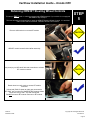
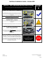
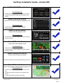
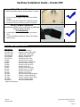
1
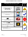
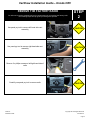
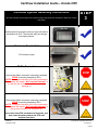
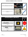
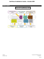
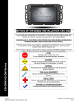
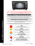
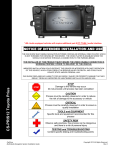
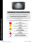
NOTICE OF INTENDED INSTALLATION AND USE THE CAR SHOW MULTI-MEDIA NAVIGATION SYSTEMS CONTAIN AN INTERNAL VIDEO PLAYER, WHICH IS NOT INTENDED FOR VIEWING BY THE DRIVER. THE VIDEO PLAYER IS DISABLED WHEN THE VEHICLE IS IN MOTION THROUGH A CONNECTION TO THE PARKING BRAKE. THE INSTALLER OF THIS PRODUCT MUST INSURE THE VIDEO DISABLE CONNECTION IS WORKING PROPERLY PRIOR TO DELIVERY OF THE VEHICLE. IMPROPER INSTALLATION COULD DISTRACT THE DRIVER OR INTERFERE WITH SAFE OPERATION OF THE VEHICLE, WHICH COULD RESULT IN SERIOUS INJURY OR DEATH, AND COULD ALSO VIOLATE STATE AND/OR FEDERAL LAW. CAR SHOW DISCLAIMS ANY LIABILITY FOR ANY BODILY INJURY OR PROPERTY DAMAGE THAT MAY RESULT FROM ANY IMPROPER OR UNINTENDED INSTALLATION AND/OR USE. STOP CS-CRV12 Honda CRV Damage to the vehicle may occur Do not proceed until process has been completed CAUTION CAUTION CarShow Multi-Media Navigation System Installation Guide Process must be carefully observed in order to reduce the risk of damage to the accessory or vehicle CRITICAL Process must be carefully observed in order to ensure a quality installation TOOLS and EQUIPMENT Specific tools and equipment recommended for this process SAFETY RISK Observe safe practices, this process can be dangerous and there is a risk of personal injury TESTING and TROUBLESHOOTING Content specific testing and troubleshooting points Copyright 2013 All Rights Reserved Rev A CarShow Installation Guide – Honda CRV PREPARING FOR THE INSTALLATION Before you start, please read these critical steps below STEP 1 BEFORE YOU START THE INSTALLATION, READ THIS GUIDE! CHECK THE BATTERY Test the battery voltage to make sure it’s fully charged This only takes seconds and can save hours of troubleshooting later. TURN THE VEHICLE OFF Keep the Vehicle Off during the installation to avoid setting various Vehicle Faults Keep the Vehicle OFF during the installation Failure to follow this may cause the AIRBAG FAULT SENSOR to become enabled. Dealer Service Departments charge a significant fee to reset the Fault Sensor. Tools Required For Installation: Panel pry/removal tool Various size Phillips screw drivers CarShow Installation Guide Copyright 2013 All Rights Reserved CS-CRV12-3 Page 2 CarShow Installation Guide – Honda CRV REMOVE THE FACTORY RADIO You will need to remove multiple interior trim components prior to removing the factory radio. The following steps will help guide you through this process. Use panel pry tool to remove left hand side vent assembly Use panel pry tool to remove right hand side vent assembly STEP 2 CAUTION CAUTION Remove 2 x phillips screws on left/right hand side of radio Carefully use panel pry tool to remove radio CarShow Installation Guide CAUTION Copyright 2013 All Rights Reserved CS-CRV12-3 Page 3 CarShow Installation Guide – Honda CRV Carefully use panel pry tool to remove radio Carefully unplug hazard switch assembly at top of radio Carefully pull out factory radio. Be sure to unplug all harnesses. CAUTION CAUTION CAUTION Remove 2 phillips screws to remove hazard switch assembly from OEM radio. Remove 3 white clips from top of OEM radio. Set these clips aside as they will be relocated to CarShow unit. CarShow Installation Guide CAUTION Copyright 2013 All Rights Reserved CS-CRV12-3 Page 4 CarShow Installation Guide – Honda CRV CarShow System Assembly Instructions This step will walk you through how to attach/connect vehicle-specific faceplate to Electronic Control Unit (ECU) STEP 3 Vehicle-specific face plate (shown at right) will need to be attached to ECU. This step will walk you through this simple process. Electronic Control Unit ECU shown at right 28-Pin Connector Be sure that 28-pin connector is securely connected PRIOR to securing faceplate to ECU. NOTE: If faceplate connector is not fully connected to ECU, system will display “No Faceplate Detected” in the top Nav bar of the menu screen when unit is powered on. ECU/Faceplate Assembly Be sure that 28-pin connector is securely connected PRIOR to securing faceplate to ECU. NOTE: If faceplate connector is not fully connected to ECU, system will display “No Faceplate Detected” in the top Nav bar when unit is powered on. Insert tabs from ECU into bottom of faceplate, and then rotate faceplate towards the ECU until snapped into place. CarShow Installation Guide Copyright 2013 All Rights Reserved CS-CRV12-3 Page 5 CarShow Installation Guide – Honda CRV Make sure alignment tabs are properly inserted into tabs from faceplate Faceplate/ECU Alignment Verify faceplate bracket screw holes are aligned to ECU mounting screw holes. Make sure 28-pin connector is tucked completely inside faceplate cavity as shown at right Mounting Screws Verify faceplate bracket screw holes are aligned to ECU mounting screw holes. Be sure that all 4 (2 left/ 2 right) Phillips screws are screwed in tightly to avoid damage to faceplate/ECU. Mounting Screw Verification Be sure that all 4 (2 left/ 2 right) Phillips screws are screwed in tightly to avoid damage to faceplate/ECU. Re-install 3 clips that were removed in step 2 to CarShow unit as shown at right. CarShow Installation Guide Copyright 2013 All Rights Reserved CS-CRV12-3 Page 6 CarShow Installation Guide – Honda CRV Re-install 2 phillips screws that were removed in Step 2 to mount OEM hazard switch to CarShow unit. Be sure to mount included mounting brackets to CarShow unit LOCATING REMOTE COMPONENTS You will need to mount the GPS and Optional Satellite Radio Antennas on the exterior of the vehicle. And mount the iPod Interface Connector in the vehicle. The following steps will help guide you through this process. STEP 4 Use Caution around SRS Components It is the installer’s responsibility to ensure that the safety equipment in the vehicle is NOT adversely affected by installation of this system. Ensure that the routing of the harnesses do NOT obstruct airbags, SRS or other safety devices. Mount the GPS and Sat Radio antenna on the EXTERIOR of the Vehicle Route the GPS harness away from other power harnesses in the vehicle. This will help to ensure optimum performance of the GPS system. CarShow Installation Guide Copyright 2013 All Rights Reserved CS-CRV12-3 Page 7 CarShow Installation Guide – Honda CRV Retaining OEM BT Steering Wheel Controls This step is ONLY used on vehicles equipped with OEM Bluetooth. If your vehicle is not equipped with OEM BT skip to step 6. This step will walk you through how to retain the OEM BT Steering Wheel Controls. It is provided ONLY so BT SWC are retained. OEM BT will NOT be functional. Remove shift knob trim to access BT module STEP 5 CAUTION OEM BT module located behind shifter assembly Use panel pry tool OR small flat head screwdriver to release BT module connector CAUTION Reach down into radio cavity to access BT module connector. Yellow lead (Pin# 15 shown at right) gets connected to “BT-SWC” wire coming off of CarShow SWC harness. Make connection using a 3M T-Tap and male spade. Do NOT reconnect BT module connector to BT module. Reach down CarShow Installation Guide Copyright 2013 All Rights Reserved CS-CRV12-3 Page 8 CarShow Installation Guide – Honda CRV INSTALL THE CARSHOW NAVIGATION SYSTEM You will need to prepare the CarShow Navigation System for installation in the vehicle. STEP 6 Connect the Power and GPS Harnesses The GPS Harness must be properly seated into connector. Also be sure steering wheel control connector is securely connected. Failure to follow this step may result in poor GPS signal and steering wheel controls being inop. Connect Optional Harnesses such as Satellite Radio, Camera These harnesses must be fully engaged prior to the system installation. See the Main Harness Diagram below for more information Turn the vehicle ON and confirm the unit is fully operational With the connectors Fully Engaged, turn the vehicle on and press the RESET located behind SD card access door. Insert a DVD to confirm the Video Disable Circuit is properly Operating. The wire of the main Honda harness labeled “Brake” (pink) must be connected to the “Brake” wire (pink) of the Honda CAN harness. CarShow Installation Guide Copyright 2013 All Rights Reserved CS-CRV12-3 Page 9 CarShow Installation Guide – Honda CRV ENABLE INSTALLER SETTINGS You will need to select certain Installer setting based on any Optional Equipment that you may have installed STEP 7 Launch the Installer Setting Screen From any screen with the Menu Button, follow these steps to display the Installer Setting Screen: 1) From any Screen, select “Menu” 2) From the Menu Screen, select “Settings” 3) Press “Keypad,” Press “1120” and “Enter” Select the individual Settings as needed for the installed components Selectable options vary by product and installation. Select the options as applicable for the installed optional components. Perform Pre-Delivery Tests You will need to perform several Pre-Delivery Tests to ensure customer satisfaction Some equipment may be optional STEP 8 Turn the vehicle ON and System ON Confirm the unit starts up properly Troubleshooting 1) Reset the System while the Vehicle is ON 2) Confirm all connectors are properly installed 3) Check the Vehicle and System Fuses Select RADIO as the Source Confirm that the AM and FM reception are as expected Troubleshooting 1) Confirm Antenna is properly connected. 2) Reset the System CarShow Installation Guide Copyright 2013 All Rights Reserved CS-CRV12-3 Page 10 CarShow Installation Guide – Honda CRV Select SATELLITE RADIO as the Source Troubleshooting 1) Confirm the antenna has unobstructed view of the sky 2) Confirm the antenna is located on the outside of the vehicle Select iPod as the Source Confirm iPod is communicating and playback is OK Troubleshooting 1) Confirm the harnesses are properly engaged 2) Reset the System Select CD as the Source Confirm CD audio playback is OK Troubleshooting 1) Confirm the disc is store bought and in good condition 2) Reset the system Select DVD as the Source Confirm DVD video playback is OK Troubleshooting 1) Ensure the Park Brake is set to view video 2) Confirm the disc is store bought and in good condition 3) Reset the system Select Phone as the Source Confirm Phone Pairing is successful Consult Quick Start Guide for Bluetooth pairing instructions Select NAV as the Source Confirm the Navigation loads and signal strength is OK Troubleshooting 1) Confirm the antenna has an unobstructed view of the sky 2) Confirm the antenna is located on the outside of the vehicle 3) Confirm the antenna is properly connected CarShow Installation Guide Copyright 2013 All Rights Reserved CS-CRV12-3 Page 11 CarShow Installation Guide – Honda CRV Select Reverse Camera Confirm the backup camera screen shows in reverse Troubleshooting 1) Confirm “Reverse Trigger” is set to ON in the Installer Settings 2) Confirm the Reverse Trigger wire is attached properly 3) Confirm the Camera is receiving 12VDC as required Verify CANBus Operation Verify Steering wheel control, Illumination and dimming functions operate properly Troubleshooting 1) 2) 2) 3) Confirm SWC/CAN harness is properly connected to ECU Confirm CAN-Module (Shown at right) is connected to SWC harness Service and Optional Parts List Part Number PP-HON-MAIN PP-HON-CAN PP-CRV-LINK PP-HON-ANT PP-CRV-BKT CS-CRV12-3 PP1005 PP1006 PP1007 PP1008 PP1009 PP1011 PP1012 PP1014 PP1010 * DP-1047* DP-1066* DP-1067* DP-1068* PP-SATKIT* * Optional Accessories CarShow Installation Guide Description Harness, Honda Main Harness, Honda CAN & SWC CAN Module, Honda CRV Adaptor, Honda Antenna Bracket, Honda CRV Installation Guide, CRV Antenna, GPS, 5 meters Ground Plate, GPS Antenna Harness, Dolby 5.1/Amp Harness, AUX IN/Cam In Harness, AUX Out Harness, External BT Mic Harness, AUX in 3.5/RCA Display Cleaning Cloth Harness, Sirius Tuner GPS Antenna Windshield Mount Camera, License Plate Black Camera, License Plate Chrome Camera, Universal Black Kit, Sirius Satellite Radio Copyright 2013 All Rights Reserved CS-CRV12-3 Page 12 CarShow Installation Guide – Honda CRV Harness Diagram Back Of CarShow Unit CarShow Installation Guide Copyright 2013 All Rights Reserved CS-CRV12-3 Page 13 CarShow Installation Guide – Honda CRV CarShow Installation Guide Copyright 2013 All Rights Reserved CS-CRV12-3 Page 14