1
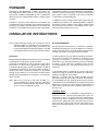
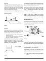
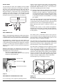
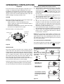
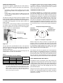
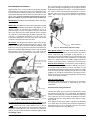
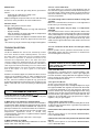
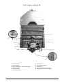
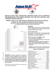
Instantaneous gas water heater
ELECTRONIC IGNITION
Model
WR 400-7.K..
• installation
• operation
• maintenance
The Bosch instantaneous water heater is a high efficiency,
space saving answer to your water heating needs. All Bosch
instantaneous water heaters heat water only as required; no
energy is lost maintaining a large volume of water at elevated
temperatures as in tank-type storage water heaters.
Suitable for heating potable water only – not approved for
space heating purposes.
READ INSTRUCTIONS CAREFULLY BEFORE INSTALLING
6 720 606 560 CA (05.05) AL
NOTICE TO INSTALLER: Please leave this
manual with the owner or affix adjacent to
appliance.
ASTRAVAN DISTRIBUTORS, LTD.
123 Charles Street
North Vancouver, B.C. V7H 1S1
Phone Canada: (604) 929-5488
Phone USA:
(206) 860-8448
Web Site: www.astravan.com
WARNING: If the information in this
manual is not followed exactly, a fire or
explosion may result causing property
damage, personal injury or death.
- Do not store or use gasoline or other flammable vapors and liquids in the vicinity of this or
any other applicance.
- WHAT TO DO IF YOU SMELL GAS
• Do not try to light any appliance.
• Do not touch any electrical switch; do not use
any phone in your building.
• Immediately call your gas supplier from a
neighbor’s phone. Follow the gas supplier’s
instructions.
• If you cannot reach your gas supplier, call the
fire department.
- Installation and service must be performed by
a qualified installer, service agency or the gas
supplier.
Note: In case of problems please contact your salesman or installer
DIMENSIONS
Figure 1
Maximum hydrostatic water pressure - 1.03 MPa (150 p.s.i.)
Maximum recommended working pressure - 0.69 MPa (100 p.s.i.)
Minimum working pressure - 0.0138 MPa (2 p.s.i.) at 2 Litres/min. (0.5 U.S. gals./min.).
Model
WR 400-7.K..
Type of Gas
Altitude
Input
Main Burner Orifices
Size, mm
Qt.
natural
standart
34.28 kW
1.20 diam.
18
propane/LP
(0-2,000 ft.)
(117,000 Btu/hr)
0.79 diam.
18
natural
high *
30.85 kW
1.20 diam.
18
propane/LP
(2,000-4,500 ft.)
(105,000 Btu/hr)
0.79 diam.
18
* The high altitude ratings listed are Canadian Gas Association high altitude ratings and are valid only in Canada.
In the U.S., the National Fuel Gas Code, ANSI Z223.1-1988, recommends for high altitude installations above 2,000
feet, that the input rate be reduced 4% for each 1,000 feet above sea level. - See page 8.
2
6 720 606 560
FORWARD
The design of the WR400-7.K.. complies with CAN 1-4.3
and ANSI Z21.10 (latest edition) as an instantaneous gas
water heater. In addition, the WR400-7.K.. also complies with
CAN 1-2.17 for use at high altitudes, 2.000 – 4.500 ft. above
sea level.
Installation, operation and maintenance information are
provided in this manual. Installation and operation instructions
should be thoroughly reviewed before proceeding with
installation of the BOSCH instantaneous gas water heater.
The BOSCH instantaneous gas water heater is designed to
operate on natural or propane gas; however, make sure that
gas on which heater is to operate is the same as specified
on the heater’s model/rating plate.
In addition to these instrutions,the water heater shall be
installed in accordance with CAN/CGA-B149 Installation
Code (in Canada) or Z223-1- latest edition, National Fuel
Gas Code (in U.S.A.) and/or local installation Code. These
shall be carefully followed in all cases.
INSTALLATION INSTRUCTIONS
Note: Proper plumbing, venting, gas connections and an
adequate supply of combustion air are required for
safe and reliable operation. Ability equivalent to that
of a licensed tradesman in the field involved is required
for installation and/or servicing of these water heaters.
AIR REQUIREMENTS
LOCATION
In order to prevent corrosion, make sure that the combustion
air is kept free of aggressive substances. Substances that
specially contribute to corrosion are halogenated
hydrocarbons (e.g. chlorine and fluorine), which are contained
in solvents, paint, adhesives, propellant gases, various
household cleaners, etc. Take precautionary measures as
necessary.
Before installing the BOSCH instantaneous gas water heater
consideration must be given to proper location.
The location should be as close to a chimney or gas vent as
practicable, in an area with an adequate air supply and as
centralized with the piping system as possible. The heater
should not be located in an area where it will be subject to
freezing. The heater should be located in an area where
leakage of the heater or its connections will not result in
damage to the area adjacent to the heater or to lower floors
of the structure.
Note: When such locations cannot be avoided, it is
recommended that a suitable drain pan, adequately
drained, be installed under the water heater. The pan
must not restrict combustion air flow.
For safe operation, sufficient air for combustion, ventilation
and dilution of flue gases must be available. An insufficient
supply of air will result in a yellow luminous burner flame,
causing carboning or sooting of the heat exchanger.
In unconfined spaces, in buildings of normal construction,
infiltration normally is adequate to provide air for combustion,
ventilation and dilution of flue gases.
However, a confined space must be provided with two
permanent openings to provide combustion and ventilation
air to the appliance. Each opening shall have a free area of
one square inch per 1000 BTU/Hr* of total input rating of all
appliances in the enclosure. One opening shall be within 12
inches of the top and one within 12 inches of the bottom of
the enclosure.
* SPECIAL NOTE
When the WR400-7.K.. is installed in a confined space of
minimum size the openings described above must be
increased to a size of 1½ square inches per 1000 BTU/Hr.
In other words, when installed in a minimum sized confined
space the two openings that are to be made in the enclosure
within 12 inches of the top and 12 inches of the bottom must
each have a minimum free area of, (1½”) x (117)= 175.5 square
inches.
6 720 606 560
3
For either a confined or unconfined space in a building of
tight construction with inadequate infiltration, air must be
drawn from the outdoors or from spaces that freely
communicate with the outdoors. Two permanent openings
located as indicated are to be provided as follows:
1.
2.
When communicating with outdoor directly, or by
means of vertical ducts, each opening shall have a
free area of not less than one square inch per 4000
BTU/Hr of total input of all appliances in the space.
When communicating with outdoor by means of
horizontal ducts, each opening shall have a free area
of not less than one square inch per 2000 BTU/Hr of
total input of all appliances in the space.
MOUNTING
The WR400-7.K.. is designed certified for mounting to a wall.
The heater must not be installed on a carpeted wall. The
heater must be mounted to the wall using appropriate
anchoring materials.
Note: If wall is a stud wall sheathed with plasterboard it is
recommended that support board(s), either 1x4’s or
½‘’ (minimum) plywood first be attached across a pair
of studs and then the heaters should be attached to
the support boards. See Figure2.
For detailed requirements see:
in Canada, CAN 1-B 149 Installation Codes
in U.S.A., ANSI Z223.1- latest edition, National Fuel
Gas Code.
WALL STUDS
SUPPORT BOARD
WARNING!
1.
2.
Flammable materials, gasoline, pressurized containers,
or any other items or articles that are potentially fire
hazards must never be placed on or adjacent to the
heater. The appliance area must be kept free of all
combustible materials, gasoline and other flammable
vapors and liquids.
Do not obstruct the flow of combustion and ventilation
air to the appliance.
1” X 4”
SPACE BOARD
Figure 2
CLEARANCE
The WR400-7.K.. is designed certified for installation on a
combustible wall and for installation in an alcove or closet
with minimum clearances to combustible construction of 0
mm from back, 102 mm (4 inches) from sides, 305 mm (12
inches) from top an bottom, and 102 mm (4 inches) from
front. A minimum of 305 mm (12 inches) shall be allowed for
maintenance of serviceable parts. Clearance from vent is
dependant upon the clearance rating of the venting material
used; that is, type B-1 vent is approved for 1 inch clearance,
B-2 vent for 2 inches, etc.
Expansion and contraction of piping due to changing water
temperature in the pipes imparts movement to the heater
which, if mounted directly to a brittle, friable board, such as
plasterboard, can cause failure of mounting.
Warning!
Check Flue Gas Safety Device good functioning, please proceed as explained in "Flue gas safety device" page 9.
THIS APPLIANCE MUST BE INSTALLED IN ACCORDANCE WITH THE NATIONAL FUEL GAS CODE
ANSI Z223.1- latest edition in U.S.A. or CAN/CGA- B149 INSTALLATION CODES IN CANADA, LOCAL
CODES AND/OR THE REQUIREMENTS OF THE AUTHORITY HAVING JURISDICTION MUST BE
FOLLOWED.
4
6 720 606 560
DRIP TRAY
If the water heater is being mounted above a floor of
combustible construction the drip tray (shipped loose in the
carton with the water heater) must be attached to the bottom
of the front cover of the water heater at the time of installation.
The drip tray should be attached to the front cover, using
screws provided, as shown in Figure 3.
Failure to use drip tray when installing unit above a floor of
combustible construction will cause an unsafe condition and
possible fire and will be in violation of A.G.A and C.G.A.
certification of the unit.
For high altitude use the adapter must be installed as shown
in Figure 4, without alteration, before connecting the six inch
flue to the unit. The adapter must be secured to the draft
diverter outlet with a minimum of two screws.
Also, in Canada, the gas pressure regulator supplied with
the water heater is factory preset to deliver gas to the water
heater at the proper pressure setting for high altitude
operation, see PRESSURE REGULATION section of this
manual, table 1 on page 8.
WARNING!
Failure to increase vent size on WR400-7.K.. to six inches
and/or to assure that manifold is set to proper value listed
on rating plate for applications at altitudes in range 2.000 to
4.500 ft. above sea level will cause unsafe venting,
asphyxiation, and voids C.G.A. certification.
WATER CONNECTIONS
SCREWS
INCANDESCENT PARTICLE TRAY
The BOSCH instantaneous water heaters are provided with
two S-bend water connectors/adapters that must be
connected to inlet and outlet connections on water valve
assembly, see figure 5 below.
Figure 3
VENTING
The BOSCH instantaneous water heaters have built- in draft
diverters and are designed for indoor installation only. The
draft diverter outlet must be connected to a clear,
unobstructed vent of the same size, or lager, refer to:
-
in Canada, CAN/CGA – B149 Installation Code for
detailed requirements.
In U.S.A., ANSI Z223.1- latest edition, National Fuel
Gas Code for detailed requirements.
The flue connection for the WR 400-7.K.. is 130mm (5
inches); however, in Canada for installation at high altitude
(2.000-4.500 ft, above sea level) a six inch (6’’) flue is
required, in Canada a 5’’x 6’’ adapter is required with the
WR400-3.K.. high altitude installations.
5” X 6” ADAPTOR
USED ON HIGH ALTITUDE
Figure 5
The purpose of the S-bend water connectors/adapters is to
provide threaded water connections that meet standards
used in North America, ANSI Standard Taper Pipe Thread
(1 ½“ NPT).
The cold water should be connected to S-bend attached to
inlet of water valve and hot water connection should be made
to S-bend attached to outlet of water valve.
If plastic piping is to be used, a 1.5 meter (approx. 5 feet)
length of metal piping must first be attached to both the cold
water inlet and hot water outlet of the water heater.
Figure 4
6 720 606 560
Note: A shut-off valve should be placed in the cold water
supply line to the heater to facilitate servicing the
heater.
5
RELIEF VALVE
The listed pressure relief valve supplied must be installed
near the hot water outlet at time of installation of the heater.
No valve is to be placed between the relief valve and the
heater. A drain line must be connected to the relief valve to
direct discharge to a safe location. Do not install reducing
coupling or any other restriction in the discharge line. The
discharge line must be installed so as to allow complete
drainage of both the valve and the line. See figure 6.
Check to make sure that the gas listed on the rating plate is
same as gas listed on the pressure regulator. See
PRESSURE REGULATION section of this manual for
information regarding gas pressure settings.
Note: Before attaching the gas supply line, be sure that all
gas pipe is clean on the inside. To trap any dirt or foreign
material in the gas supply line, a drip leg must be
incorporated in the piping. The drip leg must be readily
accessible and not subject to freezing conditions. Install
in accordance with the recommendations of serving
gas supplier.
Joint compounds (pipe dope) shall be applied sparingly and
only to the male threads of pipe joints. Do not apply
compound to the first two threads. The joint compound must
be resistant to the action of liquified petroleum gases.
Before placing water heater in operation check for gas
leakage.
Soap and water solution, or other material acceptable for
this purpose, shall be used in locating gas leaks. Matches,
candles, lighters, or other ignition sources shall not be used
for this purpose.
Figure 6
WARNING
GAS CONNECTION
Before connecting the gas supply to the heater check heater’s
model/rating plate to make sure that gas on which heater is
to operate is the same as specified on the model/rating plate.
The heater and its individual shutoff valve must be
disconnected from the gas supply piping system during any
pressure testing of the gas supply piping system at test
pressures in excess of 3,45 KPa (½ psig).
The WR400-7.K.. instantaneous gas water heaters are
supplied with a gas pressure regulator that must be installed
on the heater before attaching the gas supply line, see figure
7. Failure to install the gas pressure regulator as show in
figure 7 will be a violation of A.G.A and C.G.A certification
of the unit.
The water heater must be isolated from the gas supply piping
system by closing its individual manual shutoff valve during
any pressure testing of the gas supply piping system at test
pressures equal to or less than 3,45 KPa (½ psig).
BOSCH water heaters are shipped from the factory with
the gas pressure regulators preset for the gas shown on the
rating plate to the correct pressure:
in Canada, for high altitude operation;
in U.S., for standard altitude operation unless specially
marked as a high altitude unit.
The water heater, including the pressure regulator provided
with it, must not be operated at gas supply pressures in
excess of 3,45 KPa (½ psig). If overpressure has occurred
such as trough improper testing of the gas lines or emergency
malfunction of the supply system, the gas valve and regulator
must be checked for safe operation. Make sure that the
outside vent valves are protected against blockage. These
are part of the gas supply system, not the water heater.
Vent blockage may occur during ice storms.
GAS INLET PIPE
PRESSURE TAP
T
Figure 7
GAS MANIFOLD PRESSURE TEST POINT
T For measuring correct regulator operating pressure.
6
G662_042
PRESSURE REGULATOR
Figure 7 a)
Gas Burner
test point D for measuring pressure at full flow and input
6 720 606 560
OPERATING INSTRUCTIONS
WARNING!
If the water heater has been damaged or exposed to fire or
sooting, or if any part has been underwater, do not use.
Immediately call a qualified service technician to inspect the
appliance and to replace any part of the control system and
any gas control which as been underwater and to clean the
heater exchanger assembly and water valve.
FILLING
Before proceeding with operation of the water heater make
sure that the system is filled with water:
Make sure drain is closed. See figure 8, below.
Open a nearby hot water faucet to permit the water to
fill the heater and piping.
- Close the hot water faucet after the water flows freely
and all air has escaped from the system.
The water heater is now ready to be lit.
WATER VALVE
TO HEAT EXCHANGER
FROM HEAT
EXCHANGER
LIGHTING AND OPERATING INSTRUCTIONS
1. STOP! Read the safety information above on this label.
2. The gas valve must be shut off by putting the ON/OFF
”. Wait five (5) minutes to clear
switch to position “
out any gas. If you smell gas, STOP! Follow “B” in the
safety information above. If you do not smell gas, go to
the next step.
3. This water heater is equipped with a safety pilot burner
and an automatic ignition control system.
4. Set the ON/OFF switch to the “
” position. In this
position, the water heater is ready to use. (See Figure
9).
5. Turn the hot water faucet on the minimum flow rate
required to activate the heater. The automatic ignition
system first ignites the safety pilot burner which then
ignites the main burner in about 4 seconds. Green LED
indicator is on when main burner is on.
6. If the red LED indicator light is flashing, this is a warning
that water pressure isn’t enough to ignite the main burner.
7. The pilot flame will extiguish 10-30 seconds after the
burners come on. The burners will remain on until the
hot water tap is turned off.
NOTE: On a first time the initial installation, existence of air
in the gas supply line and in the water line may cause some
ignition delay. In that case, repeatedly open and close the
hot water tap in order to restart the ignition process until all
the air has been purged.
TO TURN OFF GAS TO APPLIANCE
DRAIN PLUG
Turn off the manual lever on the gas supply line to the heater
and set the ON/OFF switch to the OFF (
) position.
Figure 8
SERVICE HINT
The screen (strainer) in the water valve, located in the inlet
of the water valve, may require occasional cleaning due to
foreign material in the water supply. This will restrict the flow
of water and may affect heater operation and prolong filling
time. To inspect the strainer, close the cold water supply
valve ahead of the heater, disconnect the S-bend from the
inlet of the water valve and remove strainer from inlet.
Clean if required, replace strainer in inlet to the water valve,
reconnected S- bend and turn on water supply.
Light the water heater in accordance with the instructions
on the Lighting and Operating Plate on the water heater.
For your convenience, the instructions are repeated here:
To start and to shut down
the appliance press the
button “ ”.
The switch is located
behind t he flip down
cover plate on the front
panel strip.
- on
- off
Green light on =
main burner on.
Green light off =
main burner off.
If the red light is flashing,
that means the water flow
is not enough to ignite the
burner.
Figure 9
6 720 606 560
7
PRESSURE REGULATION
The pressure regulator supplied with the water heater is
adjusted to operate on the gas specified on the rating plate
and:
- in Canada, is factory preset to deliver gas at the high
altitude setting listed on the rating plate and as shown
below.
- in the U.S.A., is factory preset to deliver gas at the
standard altitude setting listed on the rating plate and
as show below.
The pressure setting of the gas pressure regulator should
be checked at installation to assure that the setting is correct
for the gas being used and the altitude at which the appliance
is installed. See rating plate on the unit, Table 1, below, for
proper setting.
In Canada for a heater being installed at standard altitude
(0- 2.000 ft. above sea level) the manifold pressure should
be reset at installation to the value shown on the rating plate,
or Table 1, below, for standard altitude.
TEMPERATURE REGULATION
The BOSCH WR400-7.K.. is equipped with a modulating
gas valve which adjusts the flow of gas to the main burner in
proportion to the water flow rate. Within its heating capacity
the WR400-7.K.. attempts to maintain the set temperature
rise across the heater. This temperature rise can be set in
range of 25ºC-to-50ºC (45ºF-to-90ºF), by means of the water
flow selector. See figure 11. When the water flow selector is
turned to the right hand stop the water heater is set for 50ºC
(90ºF) temperature rise; when the water flow selector is set
to the left hand stop it is set for 25ºC (45ºF) temperature
rise.
Temperature Adjustment Knob
Decrease
temperature and
increase flow
Increases
temperature and
decreases flow
T
ADJUSTABLE
PRESSURE REGULATOR
G661_004
MANIFOLD TEST
PRESSURE TAP
Your appliance dealer and/or local gas supplier should be
consulted in regard to any high altitude installation. If field
adjustment is required it should be performed by a qualified
serviceman experienced in such work.
Figure 11 - Principles of Operation
Figure 10
The gas pressures specified below refer to flow pressure
taken at the pressure tap in the gas inlet pipe just above the
pressure regulator, (see figure 10) while the heater is
operating at full input.
Gas pressures read at burner test point D (see fig.7 (a)) will
usually read 1-1.5’’ W.C. less than below.
Table 1
Appliance Regulator Pressure Setting
Type of Gas
natural
propane
natural
propane
Pressure tap
kPa
Inches, W.C.
1.41
5.7
2.61
10.5
1.14
4.6
2.09
8.4
Altitude
standart
(0.2,000 ft.)
high*
(2,000-4,500 ft.)
* Note: The high altitude ratings listed are Canadian Gas
Association high altitude ratings for the appliances and are
only valid in Canada. In the U.S. the National Fuel Gas Code,
ANSI 1-1988, recommends for high altitude installations,
above 2000 feet that the input rate be reduced 4% for
each 1.000 feet above sea level.
8
With the water flow selector turned to its right hand stop
position (50ºC rise setting) and with an inlet water
temperature of 10ºC (50ºF) the outlet water temperature will
be maintained at approximately 60ºC (140ºF) in the water
flow rate range of approximately 2 litres/min (0.5 U.S. gals./
min.) to 8 litres /min. (2.1 U.S. gals./min.).
The minimum flow rate for operation, the “Threshold Flow
Rate” referred to in the lighting instructions is 2 Litres/min
(0.5 U.S. gals./min). If the water flow rate is below this level
the main burner will not fire. If flow rate exceeds 8 litres/min
(2.1 U.S. gals./min.) the temperature rise across the heater
will decrease in proportion to the rate above this temperature.
HIGH TEMPERATURE LIMIT SWITCH
The BOSCH series instantaneous gas water heaters are
equipped with a high temperature limit switch with a set point
of approximately 90ºC (195ºF). If the water temperature at
sensing points exceeds the set point the switch will open,
interrupting the safety circuit and stopping gas flow to the
pilot and main burner.
Outage as the result of high limit operation indicates that the
heater is not functioning properly. The heater should be
checked by a qualified serviceman and the reason for the
malfunction corrected.
6 720 606 560
MAINTENANCE AND SERVICE
Approximately once a year, the Bosch should be checked,
cleaned and serviced as necessary. To remove the front cover,
first remove the incandescent particle tray, then pull off the
temperature adjustment knob and unscrew and remove the
plastic collar. THE FOLLOWING OPERATIONS SHOULD
BE PERFORMED BY A QUALIFIED SERVICE PERSON:
Do not use any wire or sharp object to clean orifices. Natural
gas orifices are large enough that you can usually clean them
by blowing through them. LP orifices, on the other hand, are
too small to clean and should be replacement. To access
the pilot orifice, remove 2 screws holding pilot assembly in
place. Then loosen compression fittings to expose pilot
orifice.
Vent System: Should be checked annually. Clean and repair
as needed.
Water Valve (Part #24): The water valve on this heater should
be serviced periodically. The frequency will depend on the
mineral content of the water and conditions of use or
whenever signs of corrosion appear at the gas and water
valve joint. Check that the water inlet filter (# 27 on figure
16, page 14) is clean. Diaphragm should be replaced every
7-8 years in residential applications and 3-5 years for
commercial applications. In acid water areas the venturi
should also be replaced at the same time.
Pilot Flame: The pilot flame should burn with a clean, sharp,
blue flame and should resemble the diagram in Fig. 12. If the
flame is soft and yellow the pilot screen may be dirty or the
pilot burner orifice may need to be cleaned or replaced. The
pilot flame should be approximately 2 inches long, extending
past the flame sensor. If the flame is too small, it will not
reach the flame sensor and the burners will note come on.
3mm
Correct gap between
pilot burner tip and
electrode tip
Sparking plug
electrode
PILOT ORIFICE
Fig. 13 - Pilot burner with pilot orifice
Main Burner Flames: The main burner flames should be
blue, with a more intense blue cone in the center core. Yellow
flames could be a sign of plugged or dirty burners, or a
blockage on the heat exchangers fins. If some burners have
yellow flames while others have good flames, it is likely that
dust, lint or spider webs have partially clogged the burner
venturis. To clean the burners, contact a gas service person.
Mineral Scale Build-up: In hard water areas the Bosch,
when operated at lower temperature settings, tend not to
accumulate mineral buildup. If however, the heater is used
at the higher temperature settings and the water has a high
mineral content, periodic descaling may be necessary. The
heating coils should be flushed with a descaling solution.
Signs of scaling are rising outlet temperature and knocking
noises when water is flowing.
Pilot screen
Flue gas safety device:
The flue gas safety device must not under any circumstances
be switched off, simulated or replaced by any other
component.
Flame sensor
Sparking
plug
electrode
Fig. 12 - Characteristic Pilot Flame
To clean the pilot burner and/or the pilot orifice: Turn off
the gas to the unit. Set the ON/OFF switch to OFF (position
). Remove the cover on the heater. To do so, pull of
the temperature adjustment knob and unscrew and remove
the plastic collar. Pull main cover out toward you and lift up
and out. The pilot orifice should be cleaned or replaced. Do
not enlarge orifice.
6 720 606 560
Operation and safety precautions
The flue gas safety device checks the effectiveness of flue
gas extraction by the flue. If it is inadequate, the appliance
switches off automatically so that the combustion fumes do
not escape into the room in which the appliance has been
installed. The flue gas safety device resets after a coolingdown period.
If the appliance shuts down while in operation, ventilate the
room. Wait about 10 minutes then restart the appliance. If
the problem recurs, call an engineer. The user must never
make any modifications to the appliance.
9
Maintenance*
If faults occur on the flue gas safety device, proceed as
follows:
Undo flue gas safety device fixing screw.
Unplug igniter unit connector.
Replace damaged component with new one and refit using
the reverse of the procedure set out the table above.
Function check*
Flue gas safety device function check:
Disconnect flue pipe
Replace with pipe (about 50 cm long) with sealed end
Fit pipe vertically
Start up appliance at rated output and set temperature
control to maximum temperature.
Under those conditions, the appliance should shut down after
two minutes. Remove temporary pipe and reconnect flue
pipe.
* This work may only be carried out by an approved engineer.
TROUBLE SHOOTING
Introduction
The Bosch WR400-7.K.. burners are activated by a water
flow valve. Numerous water related problems can cause
this water valve to malfunction such as: Insufficient water
flow volume or pressure to activate the burners at its
minimum flow requirement; Dirt in the water flow valve
causing it malfunction; Sediment built-up in faucet aerators,
or shower heads; Uneven pressures between cold and hot,
(with single lever faucets) Plumbing cross over. These water
flow related problems can cause the heater to deliver less
than its full output, or to fail to ignite or to shut down
completely.
Problems are stated in upper case, bold face. Most common
causes for the problems follow in order of likelihood. The
suggested solutions require that the cover be taken off. To
do this, remove incandescent particle tray, pull off the
temperature adjustment knob and unscrew and remove the
plastic collar. Pull main cover out toward you and lift up and
out.
NO SPARK AT THE PILOT
1. ON/Off switch is not “On” (Position
).
The On/Off switch is located behind the flipdown cover plate
on the front panel strip. See fig. 9.
2. Water flow is not sufficient to activate heater.
Water flow rate at faucet is below minimum flow needed to
activate heater. When temperature adjustment knob is turned
all the way clockwise, the Bosch WR400-7.K.. requires 1/2
gallon per minute flow to activate the heater. As a reference,
this is a flow which would fill a quart jar in 30 seconds. If the
temperature adjustment knob is turned fully
counterclockwise, a flow rate of 1.1 gallons/minute is required
to activate the heater.
Red LED flashes when the water flow is not enough.
3. Water inlet filter is clogged
Water flow is restricted, preventing needed flow to activate
heater. Clean water inlet filter screen.
10
4. Cross over in water lines
To confirm there is no cross-over in the plumbing, shut off
the cold water supply to the Bosch water heater and open a
hot water faucet. There should not be any water flowing at
that faucet. Water running is a sign of a plumbing cross over.
Consult your plumber.
5. Cold incoming water connection made to wrong side
of heater
Make sure cold water inlet connection is on the right side of
heater when you are facing heater.
6. Water valve parts may be dirty or components
damaged
First check that venturi is free of dirt particles. Water valve
and component parts must be totally free of dirt. In hard water
areas, mineral deposits can eventually (3-5 years in hard water
areas) corrode the water valve parts to a point where they
may need replacing. Any sign of moisture at the top of the
water valve is a sign that the water valve needs to be serviced
immediately.
7. Loose connection at the ECO or the flue gas safety
device
Ignition sparker will not operate if the electrical circuit is
interrupted. Check that the connections to the ECO are
secure and tighten if necessary.
SPARKS APPEAR AT PILOT WHEN HOT WATER
TAP TURNED ON, BUT PILOT AND BURNERS
WILL NOT IGNITE
1. Air in the Gas Line
Normally this is a problem at time of initial installation, after
the pipes have been worked on, or after a gas supply line
has been allowed to empty. Bleed the air trapped in the gas
line by turning the hot water faucet on and off until the air
has been cleared from the line.
2. No gas to the Bosch
A. Gas cock on gas line may not be open
B. Gas regulator may be shut or damaged. Replace or unjam
the regulator. Note: The regulator furnished with the heater
is exclusively designed for low gas pressure. Excessive
pressure will lock it up. Jamming usually happens when using
propane gas if the gas pressure between the gas tank and
the water heater’s gas regulator has not been reduced. See
Page 8 for recommended correct gas pressure. To unjam a
regulator, call your gas supplier.
3. Pilot orifice or gas valve is dirty
Clogging of the pilot burner can be caused by dust in the air
or dirt in the gas. The pilot orifice or gas filter may need to be
cleaned or replaced.
5. Pilot electrovalve switch may need to be replaced (See
Fig 16).
Call your service person or call: Canada 1-800-663-8405,
U.S.A. 1.800-824-7337.
6. Electronic Control Box may need to be replaced, (See
Fig 16).
Call your service person or call: Canada 1-800-663-8405,
U.S.A. 1.800-824-7337.
6 720 606 560
PILOT LIGHTS BUT BURNERS
WILL NOT COME ON
1. Confirm water valve assembly is working properly.
2. Confirm the flame sensor is in its proper position.
3. Confirm the burner electrovalve switch is functioning
properly. Contact your service person or call:
Canada 1-800-663-8405, U.S.A. 1.800-824-7337.
4. The electrical Control Box (Fig. 16) may need to be
replaced. Contact your service person or call:
Canada 1-800-663-8405, U.S.A. 1.800-824-7337.
5. Minimum inlet pressure on well is inadequate
Check the inlet water pressure. On a private well, raise the
minimum pressure setting to 40 psi for best performance.
Confirm that the pressure tank is not water logged.
WATER IS TOO HOT
1. Check for lime build-up. (See mineral scale p. 9)
2. Temperature Selection too high
Turn the temperature adjustment knob counter-clockwise (to
the left) to lower the maximum water temperature.
Note: This will increase the activation flow rate.
3. Inlet water temperature is too hot (as with preheated
water.)
Decrease gas pressure. If this is not practical install
tempering valve at inlet and mix with cold water.
WATER IS NOT HOT ENOUGH
1. Temperature selection too low.
Change the setting. Turn the temperature adjustment knob
clockwise (to the right).
Note: This will decrease the activation flow rate.
2. Water flow through the heater is higher than the
capacity of the Bosch to heat it.
This can be due to too high water inlet pressure (60 psi max.
for best results) or due to acid water erosion of venturi. Check
venturi (Part #30, Fig. 16).
Fig. 14 - Electrical wiring diagram
1
2
3
4
5
6
7
burner electrovalve
gas control valve
pilot electrovalve
flame sensor
pilot electrode
overheat sensor
temperature limiter
8
9
10
11
12
13
electronic control box
Led failure indicator
Led indicator main
burner condition
on/off switch
power generator
flue gas safety device
MAIN BURNERS GO OUT DURING HOT
WATER USE
1. Flow rate diminished below activation rate
2. Unbalanced pressure in the water lines
The added restriction caused by the Bosch in the hot water
system can result in uneven pressures between the cold and
the hot. In such cases when mixing cold water at the tap, the
lower hot water pressure may be overpowered by a much
higher cold water pressure, which may cause the Bosch
burners to shut down. Make sure faucet aerators and
showerheads are free of minerals and dirt. Do not add any
flow restrictor to the shower head.
3. ECO (overheat sensor) tripped due to overheating
Re-ignite the appliance 10 minutes later. Contact your service person or call:
Canada 1-800-663-8405, U.S.A. 1.800-824-7337.
3. Btu input is too low due to insufficient gas pressure. It
is extremely important for a tankless instantaneous water
heater to have the right size gas line to obtain the correct
gas pressure.
See specifications on page 8. Unlike storage tank water
heaters, the burners of a tankless water heater must be very
powerful to heat water instantaneously since they do this
only at the time hot water is actually being used. It is therefore
imperative that the gas pressure requirement be met exactly.
Insufficient gas pressure will directly affect the water
temperature at the time of usage. See page 8 for correct
gas pressure settings and fig. 7 for locations where gas
pressures are taken.
4. Btu input is too low due to insufficient gas supply.
Make sure your main gas line is fully opened. If using LP
gas, be sure that the size of the propane tank is adequate to
supply the required gas pressure.
5. Cold water is mixing with the hot water between the
Bosch and the outlet.
Compare water temperature at outlet of the Bosch (hold the
Bosch’s outlet pipe with your hand) and at the tap. If these
two are very different, check for mixing valve or plumbing
crossover (see “NO SPARK AT THE PILOT” paragraph #4).
Where automatic “anti-scald” valves are required by code,
lower the temperature setting on the Bosch as much as
possible and balance the pressure between cold and hot
water after the Bosch.
4. Flue Gas safety device tripped
Ventilate the room and re-ignite the appliance 10 minutes
later. Contact your service person or call:
Canada 1-800-663-8405, U.S.A. 1.800-824-7337.
6 720 606 560
11
6. Parts in water flow valve are corroded so that the
gas valve is not fully opening.
Contact your service person or call:
Canada 1-800-663-8405, U.S.A 1-800-824-7337.
HOT WATER TEMPERATURE FLUCTUATES
1. Unbalanced pressure in waterlines.
The added restriction caused by the Bosch in the hot water
system can result in uneven pressures between the cold and
the hot. In such cases when mixing cold water at the tap, the
lower hot water pressure may be overpowered by a much
higher cold water pressure, which may cause the Bosch
burners to shut down. Make sure faucet aerators or shower
heads are free of minerals. Do not add any flow restrictor
to the shower head.
2. Cold water is mixing with the hot water between the
Bosch and the outlet.
See # 4 under “NO SPARK AT THE PILOT”.
3. Inlet water pressure is erratic due to inadequate
supply water pressure or saturated pressure tank on well
system.
Check the inlet water pressure. On a private well, raise
minimum pressure setting to 40 psi. Confirm that the pressure
tank is not water logged.
4. Gas pressure is too low.
See page 8 for correct specifications.
12
6 720 606 560
Fig.15 - Diagram of WR 400-7.K..
1
2
3
4
5
6
7
8
9
10
11
1.
2.
3.
4.
5.
6.
6 720 606 560
Heat exchanger
Pilot assembly
Burner manifold gas pressure test nipple
Main gas burner
Pilot gas tubing
Led failure indicator
7.
8.
9.
10.
11.
on/off switch
Led operation indicator
Water valve
Temperature adjustment selector
Gas inlet gas pressure test nipple
13
Fig. 16
14
- INTERIOR COMPONENTS DIAGRAM AND PARTS LIST
6 720 606 560
Fig. 16
INTERIOR COMPONENTS DIAGRAM
AND PARTS LIST WR400-7K...
1
2
3
4
5
6
7
7
8
9
10
10
11
12
12
13
14
15
15
16
16
17
18
19
20
21
22
23
24
25
26
27
28
29
30
31
32
33
34
35
36
37
38
39
6 720 606 560
Front cover
Temperature adjustment knob comp.
Temperature adjustment knob
Draught diverter
Heat exchanger
Temperature limit
Main burner
Main burner
Washer
Throttle disc ( 7.0 )
Pilot burner (41.2)
Pilot burner
Set of electrodes
Pilot injector ( 13 )
Pilot injector ( 74 )
Pilot gas pipe
Washer
Gas valve
Gas valve
Diaphragm switch
Diaphragm switch
Pilot electrovalve
Burner electrovalve
Cold water pipe
Hydro-generator
Connecting pipe
Hot water pipe
Temperature limit
Water valve
Cover
Diaphragm ( C )
Water strainer
Selector screw
Volumetric water governor
Venturi ( 23S )
Ignition unit
Cable
Ignition cable
Flue gas safety device
Set of cables
Water valve repair kit
O’ring
O’ring
Water connections gasket
¤
¤
¤
¤
¤
¤
NG
LPG
¤
LPG
LPG
NG
¤
NG
LPG
¤
¤
NG
LPG
NG
LPG
¤
¤
¤
¤
¤
¤
¤
¤
¤
¤
¤
¤
¤
¤
¤
¤
¤
¤
¤
¤
¤
¤
¤
8 705 421 742
8 702 000 219
8 702 000 111
8 705 505 354
8 705 406 235
8 707 206 132
8 708 120 298
8 708 120 296
8 710 103 060
8 700 100 174
8 708 105 491
8 708 105 337
8 718 107 067
8 708 200 069
8 708 200 312
8 700 707 370
8 700 103 173
8 707 011 917
8 707 011 945
8 708 504 021
8 708 504 049
8 708 501 249
8 708 501 250
8 700 705 972
8 707 406 043
8 700 705 947
8 700 715 080
8 707 206 040
8 707 006 353
8 705 500 101
8 700 503 053
8 700 507 001
8 708 500 289
8 705 705 026
8 708 205 279
8 707 207 085
8 704 404 040
8 704 404 039
8 707 206 235
8 704 404 038
8 703 406 178
8 700 205 120
8 700 205 119
8 710 103 043
15
0