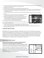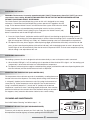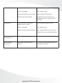
1
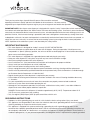
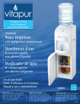
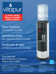
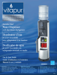
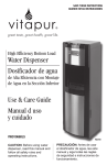
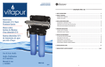
save These Instructions
Conserver ces instructionS
guarde estas instrucciones
Point-of-Use
Water Dispenser
Distributeur d’eau
au Point d’utilisation
Dispensador de Agua
a Punto de Utilización
Use & Care Guide
Guide d’utilisation
et d’entretien
Manual d uso y cuidado
VWD9506W-POU
VWD9506BLS-POU
REV03
CAUTION: Before using water
dispenser, read this manual and
follow all safety rules and
operating instructions.
Thank you for purchasing a vitapur® Water Dispenser. Please read the enclosed
operating instructions carefully and retain this booklet for future reference. We have carefully
engineered your vitapur® Water Dispenser to give you years of enjoyment and trouble free operation.
IMPORTANT NOTE: Your vitapur water dispenser is designed with a special “safety” feature (float switch mechanism)
that controls activation/operation of the “Kettle Feature” hot water tank heating system. If no water is present and/or low
water levels are detected inside the internal reservoir system, activation/operation of the hot water heating system is not
possible. Likewise, if the hot water heating is operational and water is being drawn simultaneously causing water levels
to drop below safe levels, hot water tank operation is automatically terminated until normal water levels are restored, at
which time you must “manually” re-activate the hot water heating system by pressing the kettle feature (red) button.
NOTE: Operation of the cold water system is not affected by this safety feature.
IMPORTANT SAFEGUARDS
• This water dispenser is designed for “indoor” use only. DO NOT USE OUTDOORS.
• Never turn the dispenser upside down or tilt more than 45 degrees. During transportation, if the dispenser was transported in a “prone” (sideways) position, the unit must be left to stand upright for 12 hours before connecting to power source and initiating operation.
• This water dispenser is equipped with a grounded power cord and plug for your safety.
• Keep your water dispenser in a dry place away from any heat source and direct sunlight.
• Never put anything flammable close to the dispenser.
• Leave a minimum of 2” (5cm) around the back and sides of the dispenser for proper ventilation.
• Always install your water dispenser on a level (solid) floor.
• Wait 3 minutes before restarting machine after shutting it down.
• Always unplug (disconnect) the water dispenser power cord before servicing, cleaning and filter replacement.
• Service must be performed by qualified/authorized service personnel only. Service information is available through our Customer Service Department at 1-866-253-0447.
• Regular cleaning of your water dispenser is required for your warranty.
• Please follow the cleaning and maintenance instructions outlined in this manual. Cleaning should be done every
4 ~ 6 months.
• It is your responsibility to ensure that all water line connections are properly connected and sealed and there are no system water leaks before operating the unit.
• Although this unit incorporates provision of a (hot water) “child resistant safety switch”, never allow children to dispense hot water without proper and direct supervision.
DANGER: The hot water in this dispenser is heated to approximately 90°C (194°F). Temperatures above 52°C (125°F) can cause severe burns from scalding. • Only use original (OEM) Vitapur (VSRF-9) replacement filters with this unit.
GROUNDING INSTRUCTIONS
• Improper use of the grounding plug can result in a risk of electric shock causing serious injury, even death.
• This appliance must be grounded. In the event of an electrical short circuit, grounding reduces the risk of electric
shock by providing an escape wire for the electric current.
• This appliance is equipped with a power cord having a grounding wire with a grounding plug and must be connected into a properly grounded polarized outlet. Consult a qualified electrician if the grounding instructions are
not completely understood, or if doubt exists as to whether the appliance is properly grounded. If the wall outlet is a
standard 2 prong outlet, it is your personal responsibility and obligation to have it replaced with a properly grounded
3-prong wall outlet.
• Do not under any circumstances cut or remove the third (ground) prong from the power cord plug.
• Do not use an adapter plug with this appliance.
• Do not use an extension cord with this appliance. If the power cord is too short, have a qualified electrician install an e
lectrical outlet near the appliance.
YOUR VITAPUR® WATER DISPENSER
1. Top Cover
2. Ready-To-Dispense indicator lights:
Yellow: “flashing” Low water level inside internal reservoir. Hot water heating system cannot be activated.
(you must replenish water supply)
“off”
Internal reservoir water level is sufficient to activate hot water heating system
Blue: “on”
The cold water has reached optimum temperature and is ready for dispensing
“off”
The cooling cycle is in progress, it is possible to dispense water during the cooling cycle, however, optimum cooling temperature may not yet be achieved
3. Child resistant safety switch
4. Hot water dispensing button (also dispenses room temperature water when Kettle feature is not activated)
5. Cold water dispensing button
6. Kettle Feature (on/off) activation button (self-illuminated)
“flashing” Heater (hot water tank) is operational.
“on” The hot water has reached optimum temperature and is ready for dispensing.
“off” Heater (hot water tank) is off, however remaining water within the
tank may still be very hot, always 1
exercise caution when dispensing and/or draining water from the hot water tank.
7. Removable drip tray
6
8. Adjustable COLD water thermostat
2
(rear of dispenser)
5
4
9. Drain valve (rear of dispenser)
10. Condenser coils (rear of dispenser)
3
11. Lower front panel (filter located behind)
9
12. Manual shut-off valve (water inlet) L
H
8
7
12
11
10
1
Installation INSTRUCTIONS
It is highly recommended to have your water dispenser installed by a professional (licensed) plumber. If you are
installing the water dispenser yourself, the following information is important:
Depending on the type of plumbing in your home, (copper or flexible pipe) the following plumbing installation accessories
(not included with the water dispenser) will be required to complete the installation of your water dispenser. These items
can be purchased at your local hardware store.
COPPER PIPE PLUMBING (SOLDERING REQUIRED):
• ½” Copper Tee (A)
• ½” Male Solder x ¼” OD Compression Fitting Shut Off Valve (B)
• Installation Appearance (C)
(A)
(B)
(C)
TOOLS REQUIRED:
• Soldering Flux
• Solder
• Emery Cloth
• Tube/Pipe Cutter
• Welding Torch
• Towels (water clean-up)
FLEXIBLE PIPE PLUMBING (NO SOLDERING OR GLUE REQUIRED):
• ½” x ½” x ½” Quick-Grip Tee (D)
• ½” Quick-Grip x ¼” OD Compression Fitting Shut Off Valve (E)
• Installation Appearance (F)
(D)
(E)
2
(F)
TOOLS REQUIRED:
• Plastic Pipe/Tube Cutter
INSTALLATION LOCATION:
Select a suitable location where the water dispenser will be installed, (in your home/kitchen) making sure you have easy
access to an electrical wall outlet and cold water supply line.
GETTING STARTED (MAIN WATER LINE HOOK-UP):
1. IMPORTANT: Turn off the cold water supply.
2. Open the cold water faucet allowing water to purge the system (to minimize water leakage clean-up).
3. Using a tube/pipe cutter, cut and remove a section of the cold water line at the desired height (cut should be made above any manual shut-off valve installed on the water line).
4. COPPER PIPE PLUMBING: Using emery cloth, clean both ends of the copper pipes and apply flux to “all” surfaces t o be soldered including the inside of the tee. Follow manufacturer’s installation instructions provided with the ½” Male Solder x ¼” OD Compression Fitting Shut Off Valve (B).
5. FLEXIBLE PIPE PLUMBING: Follow manufacturer’s installation instructions provided with the ½” x ½” x ½”
Quick-Grip Tee (D) and ½” Quick-Grip x ¼” OD Compression Fitting Shut Off Valve (E).
6. Close the newly installed shut-off valve (See Fig. 1A and Fig. 1B) and slowly re-open the cold water supply line and check for leaks. If leaks are detected, immediately close the water supply and repair any/all leaks. If no leaks are detected, proceed to step 7.
Fig. 1A (Valve Open)
Fig. 1B (Valve Closed)
7. The water dispenser includes 8 meters (26 feet) of ¼” OD flexible water line. If additional water line is needed, it can be purchased at your local hardware store. Cut the desired length to suit your installation requirements, making sure both ends of the water line are cut straight/square (See Fig. 1 & Fig. 2). Remove the compression nut and compression ring from the valve and install on the water line (See Fig. 3).
Fig. 1 (Correct)
Fig. 2 (Incorrect)
3
Fig. 3
Insert the water line into the valve until is stops (See Fig. 4) slide both the compression nut and compression ring toward
the valve and tighten the nut firmly using a wrench. CAUTION: DO NOT OVERTIGHTEN (See Fig. 5).
A
B
Fig. 4
8.
9.
10.
11.
Fig. 5
Fig. 6
The water dispenser is equipped with a manual “shut off” valve installed on the rear side of unit (See Fig. 6A) for easy access in case of an emergency.
Connect the incoming water line into the open side of the manual shut off valve (See Fig. 6B). This valve utilizes “quick-connect” type water line fittings (no tools required). Simply insert the end of the water line into the shut off valve and until it stops. WARNING: DO NOT OPEN THE WATER SUPPLY LINE AT THIS STAGE.
(See installation of Filter).
To disconnect (remove) the water line from the shut-off valve, you must first remove the blue locking “c-clip”
(See Fig. 14) by pulling it forward.
To release the water line, simply press and hold the “white” outer collar surrounding the line (See Fig. 15) while at the same time pulling the water line out. NOTE: The locking “c-clips” must always be installed “prior” to installation of the water lines.
INSTALLATION OF FILTER:
For hygiene purposes, the filter included inside the water dispenser has not been factory installed. It has been shipped
in its original shrink-wrapped package. The filter is located behind the lower front panel of the dispenser. To access the
filter;
• Remove the drip tray by pulling it forward. (See Fig. 7)
• Remove the Phillips screw securing the lower panel. (See Fig. 8)
• The filter is secured by 2 retaining clips. Remove, and unwrap the filter. (See Fig. 9 & 9A)
Fig. 7
Fig. 8
Fig. 9
4
Fig. 9A
UNLOCKED
Fig. 10
•
•
•
LOCKED
Fig. 11
To attach the filter to the filter head, make sure the “blue locking tab” on the front of filter head is pushed all the way up (See Fig. 10).
Screw the filter (1/4 turn clockwise) into the filter head until it stops. Push down the “blue locking tab” into the locked position (See Fig. 11) If the locking tab fails to engage, (lock) the filter is not sufficiently tightened
(Re-tighten).
The “red arrow” on the filter head identifies water flow direction (in / out) through the filter.
• The installation is now complete. As with all plumbing installations, the water supply should be turned on slowly and all connections should be inspected for leaks prior to opening all water valves fully. If any leaks are detected, immediately close the water supply and repair.
Fig. 13
•
•
Fig. 14
Fig. 15
To disconnect (remove) the water lines from the filter head, you must first remove the blue locking “c-clip” (See Fig. 14) by pulling it forward.
To release the water line from the filter head, simply press and hold the “white” outer collar surrounding the line (See Fig. 15) while at the same time pulling the water line out. NOTE: These locking “c-clips” must always be installed “prior” to installation of the water lines.
• To install the water lines, simply insert both lines into their respective openings in the filter head (approx. 13mm
or ½”) until they come to a stop.
5
WATER LEAKAGE DETECTION SYSTEM:
This water dispenser is equipped with a low voltage water leakage detection
system located inside the base of the filter compartment and is covered by a
removable drip tray (See Fig. 16). In the event any water makes contact with
the leakage detection system, an audible alarm will sound (beep) continuously
until the water is removed. Upon activation of the leakage detection system, the
water inlet solenoid valve (located internally) is automatically (closed) deactivated
suspending incoming water activity until the alarm is silenced. To silence the
alarm, any/all accumulated water surrounding the sensors, must be removed
using a sponge and/or paper towels. The water inlet solenoid valve (opens)
reactivates automatically once the alarm is silenced.
Fig. 16
FILTER REPLACEMENT:
For optimum water efficiency and performance, we recommend replacing the filter every 6 months. Replacement filters
can be ordered by contacting our CUSTOMER SERVICE DEPARTMENT (TOLL FREE) AT 1-866-253-0447 OR YOU CAN
ORDER ON-LINE AT; www.greenwayhp.com/shopping. Replacement Filter part number is VSRF-9.
CAUTION: Always turn off the water supply, using manual shut-off valve located at the rear of the dispenser, before
replacing filter. This will depressurize the water line and minimize water overspray when the filter is released. Remove
and empty drip tray under filter of any accumulated water. If the audible alarm sounds, refer to “WATER LEAKAGE
DETECTION SYSTEM” instructions.
Cleaning Kit
INITIAL PRODUCT CLEANING:
Like most appliances, your water dispenser requires periodic maintenance
for maximum efficiency and performance and must be cleaned on a regular
basis, (coincide with filter replacement i.e. every 6 months) in order to maintain
a hygienic environment and prevent potential formation (growth) of bacteria. A
cleaning kit is available through our Customer Service Department at 1-866253-0447 or can be ordered on line at www.greenwayhp.com/shopping, or you
can pre-mix a solution of 15ml (1 tbsp) bleach with 4.5L (1.2 gal) of hot water.
Available online at
1. Always disconnect (unplug) the power cord before attempting any www.greenwayhp.com
cleaning, maintenance and filter replacement.
2. Always turn off the water supply, using manual shut-off valve at the rear
of the dispenser, before attempting any cleaning, maintenance and filter replacement.
Fig. 17
Fig. 17A
6
Fig. 17B
3.
4.
5.
6.
7.
8.
9.
10.
11.
12.
13.
14.
To access the reservoir system, you must remove the top cover on the dispenser (See Fig. 17) by removing the two Philips screws located at the rear of the cover (See Fig. 17A).
Carefully lift off the top cover.
Remove the black reservoir cover by carefully pulling upward (See Fig 17B).
If using a vitapur water dispenser cleaning solution, please follow the manufacturer’s instructions provided with the cleaning kit. If using a pre-mixed solution of 15ml (1 tbsp) bleach with 4.5L (1.2 gal) of hot water, fill the reservoir and let stand for 20 min.
Press both dispensing taps until the cleaning solution stops flowing (collect the cleaning solution into a container/
bucket).
Flush the reservoir with clean water and press both dispensing taps until water stops flowing (collect the water into a container/bucket).
To drain any remaining water from the reservoirs, remove (unscrew) the drain cap and plug located at the rear of the dispenser (See Fig. 18). Collect the water into a container/bucket. IMPORTANT: Remember to
re-install the drain cap and plug and tighten (See Fig. 18).
Re-install the reservoir cover by pressing down firmly.
Re-install the dispenser top cover and secure using the two Philips screws.
Re-connect the power cord.
Fig. 18
Re-open the manual shut-off valve (you will hear water entering the system
which will stop automatically when the appropriate water levels are reached).
Place a container under the water spigots and press both dispensing buttons (separately) to make sure water is flowing normally from each side.
OPERATING INSTRUCTIONS:
IMPORTANT NOTE: Your vitapur water dispenser is designed with a special “safety” feature (float switch mechanism)
that controls activation/operation of the “Kettle Feature” hot water tank heating system. If no water is present and/or low
water levels are detected inside the internal reservoir system, activation/operation of the hot water heating system is not
possible. Likewise, if the hot water heating is operational and water is being drawn simultaneously causing water levels
to drop below safe levels, hot water tank operation is automatically terminated until normal water levels are restored,
at which time you must “manually” re-activate the hot water heating system by pressing the kettle feature (red) button.
NOTE: Operation of the cold water system is not affected by this safety feature.
Child Resistant Safety Switch:
DO NOT ALLOW CHILDREN TO USE THE HOT WATER DISPENSING
BUTTON WITHOUT PROPER AND DIRECT SUPERVISION.
To prevent hot water from being dispensed accidentally and possibly harming
a child, the hot water dispensing button can only be operated when the child
resistant safety switch is activated. To dispense hot water, push/hold the child
safety switch sideways (in the direction of the arrow located on the switch)
from right to left, then press/hold the hot water button (as soon as water starts
flowing you can release the child safety switch) until the desired amount of hot
water is dispensed. Upon releasing the hot water button, the child safety switch
automatically re-engages to the locked position.
7
Child
resistant
safety
switch
Dispensing Hot Water:
WARNING: The hot water is heated to approximately 90°C (194°F). Temperatures above 52°C (125°F) can cause
severe burns from scalding. DO NOT ALLOW CHILDREN TO USE THE HOT WATER DISPENSING BUTTON
WITHOUT PROPER AND DIRECT SUPERVISION.
The “Kettle Feature” (hot water) dispensing system on this unit is designed to save energy
and money. Conventional hot water dispensing systems operate 24/7 regardless of water
usage. The on demand “Kettle Feature” activates the hot water system only when the “Kettle
Feature” (red) button is activated delivering steaming hot water in less than 3 minutes.
To stop/cancel the “Kettle Feature” during a cycle, simply press the “Kettle Feature” (red)
button a second time and the red LED light will turn off.
1.
2.
Press the “Kettle Feature” (red) button and the red LED light will start flashing to signify the heating system is operational. The heating cycle takes approximately 3 minutes. When the heating cycle is completed, the red LED
light will change from “flashing” to a steady “on” condition (meaning water has reached optimum temperature).
To dispense hot water, place cup/glass under dispensing spigot, push/hold the child safety switch to the left and press the hot water dispensing button (with red line indicator), until the desired amount of water is dispensed. The red LED light will turn off automatically when the hot water is dispensed. NOTE: The hot water temperature (factory default setting) is not adjustable on this unit.
Dispensing Cold Water:
The cooling system on this unit is designed to activate automatically as soon as the power cord is connected.
1. When the blue LED light is “off” the cooling cycle is operational. When the blue LED is light is “on” the cooling cycle (compressor) is off and the cold water has reached optimum temperature.
2. To dispense cold water, place cup/glass under dispensing spigot, push/hold the cold water dispensing button (with blue line indicator) until the desired amount of water is dispensed.
Adjusting the Temperature (Cold Water Only)
The temperature of the cold water reservoir is controlled by a cooling thermostat
located at the rear of the dispenser. The factory default setting of the thermostat
is “mid-point” (medium) on the thermostat scale. By turning the thermostat set
screw (See Fig. 19) the temperature can be adjusted. Turn the dial clockwise
(using a screwdriver) between “L” (warm) and “H” (colder) until the desired
temperature is reached. If water is not being properly dispensed, there could be
possible ice build-up in the reservoir due to the thermostat being set too cold. If
this happens, slowly rotate the dial counter clockwise to a warmer setting.
Fig. 19
cleaning and maintenance:
See “Initial Product Cleaning” and follow steps 1 ~ 13.
grill
Cleaning the Drip Tray (Not Dishwasher Safe):
To remove, pull the drip tray towards you. Drain and clean. The drip tray should
be emptied and cleaned regularly to remove spotting and mineral deposits.
8
drip
tray
Clean with Vitapur water dispenser cleaning solution or mild soap and water mixture. For tough deposits, add vinegar
and let soak until the deposits come loose. Then wash, rinse and dry throroughly. Put the grill back on the tray and install
on the dispenser.
Cleaning the Outside of the Water Dispenser
The outside of the dispenser can be wiped clean with a vitapur® water dispenser cleaning solution or a mild soap and
water mixture. Never use harsh chemicals or abrasive cleaners. Rinse thoroughly with clean water and then dry surfaces.
Cleaning the Condenser
Vacuum or sweep away the dust from the condenser coils at the back of the
dispenser. For best results, you can purchase a brush designed specifically
for this purpose from your local appliance store. This will improve cooling and
efficiency.
Condenser
coils
INTERNAL RESERVOIR WATER OVERFLOW PROTECTION:
The internal (cold tank) reservoir incorporates a water overflow flotation device.
(See Fig. 20)
“A” is the “primary” flotation device that manually controls incoming water and
related water levels associated with normal operating conditions. The design
parameter of this device allows the float to move freely “up/down” according to
related water levels. As water levels rise, so does the float causing the water inlet
valve to close at a pre-determined level. As water levels fall, so does the float
causing the water inlet valve to open allowing replenishment of water.
L
H
B
A
Fig. 20
“B” is the “secondary” flotation device that engages “only” in the event of a malfunction of flotation device “A” to prevent
possible overflow conditions. The design parameter of this device only allows the float to move “upward” as water levels
rise, causing the water inlet valve to close permanently. When flotation device “B” engages, a manual “re-set” of the
floatation device is required in order to restore normal (incoming) water activity.
RE-SETTING WATER OVERFLOW PROTECTION:
1. Disconnect (unplug) the power cord.
2. Turn off the water supply, using manual shut-off valve at the rear of the dispenser.
3. Place cup/glass under dispensing spigot and drain approx. 3 cups of cold water.
4. Remove the top cover on the dispenser (See Fig. 17) by removing the two Philips screws located at the rear of the cover (See Fig. 17A).
5. Carefully lift off the top cover.
6. Place a towel on top of the reservoir cover.
7. Push the white re-set button located on top of the reservoir cover (See Fig. 21). A small burst of water will release from the re-set button depressurizing the water line. This action will cause flotation device “B” to release. The
re-set procedure is now complete. Clean-up any access water on the reservoir cover. Re-connect the power cord.
OVERFLOW RE-SET
8. Slowly re-open the manual shut-off valve (at the rear of the dispenser). You
should hear water entering the reservoir. If not, close the manual shut-off valve and repeat steps 1,2, 3, 6, 7, 8.
Fig. 21
9
9. Re-install the dispenser top cover and secure using the two Philips screws.
10. Re-connect the power cord.
Draining the Reservoirs:
IMPORTANT! Unplug the dispenser before performing this procedure. Dispense hot water until temperature
drops to a safe level to avoid the risk of scalding.
1.
2.
3.
4.
Turn off the water supply, using manual shut-off valve at the rear of the dispenser.
Press both dispensing buttons until water stops flowing.
Place a container/bucket beneath the drain valve located at the rear of the dispenser (See Fig. 18).
Remove the drain cap and plug from the drain valve and let the remaining water flow into the container/bucket. Replace the cap and plug.
Going Away on Vacation:
When not using the dispenser for long periods of time or when going on vacation, unplug the dispenser and drain the
reservoirs (see Draining the Reservoirs). Follow Initial Product Cleaning Procedures upon return and startup of the
dispenser.
Specifications:
VWD9506W-POU / VWD9506BLS-POU
Heating Temp (approx.):
194°F / 90°C
Cooling Temp (approx.):
39 - 54°F / 4°C - 12°C
Hot
Cold
Output per hr:
1.2 gal / 4.6 L
0.5 gal / 2.0 L
Internal Tank:
0.2 gal / 0.6 L
0.8 gal / 3.6 L
Power Consumption:
1150 W
88 W
Working Water Pressure:
Up to 120psi
TROUBLE SHOOTING TIPS:
Attention: Do not return this product to the store. For questions on operation, assembly or parts, please contact us at
www.greenwayhp.com or 1-866-253-0447.
Problem
Water dispenser is leaking.
Possible Cause
Suggested Solution
Check all water line connections for
leaks.
Repair water line connections and make sure
blue locking “c-clips” are installed on water
lines.
Filter not properly secured and locked.
Secure Filter and lock.
Drain cap and plug are not secure.
Ensure drain plug is secure and tighten drain
cap.
Cold tank reservoir is overfilled.
See RE-SETTING WATER OVERFLOW
PROTECTION
10
No hot water.
Insufficient water levels in the reservoir.
Make sure all water shut-off valves are open.
The unit is unplugged.
Plug in the power cord.
Kettle Feature button was not activated.
Activate the Kettle Feature button.
Temperature limit switch tripped.
The temperature limit switch will re-set
automatically when the temperature of the
water drops.
The circuit breaker in your home is
tripped or the fuse is blown.
Reset the breaker or replace the fuse.
The unit is unplugged.
Plug in the power cord.
Thermostat needs to be adjusted colder.
Adjust thermostat between L (warm) and H
(colder) levels to achieve desired temperature.
Water dispenser is not
dispensing water.
Water shut-off valves are closed.
Open all water shut-off valves.
Alarm is beeping
continuously.
Water leakage detection system is
activated.
Refer to Water Leakage Detection System
instructions in the manual.
No cold water.
11
Warranty
DO NOT RETURN THIS PRODUCT TO THE STORE:
Please contact Customer Service at: 1-866-253-0447 or [email protected]
Greenway Home Products warrants your water dispenser to be free from manufacturer’s defects in workmanship or material under
normal operating conditions for one (1) year from the original date of purchase. This warranty applies only in the country in which it is
sold, and is available to the original purchaser only. This warranty is non-transferable.
This warranty and the CSA International listing for this water dispenser are void if the water dispenser is altered, modified, or combined
with any other machine or device. Alteration of this water dispenser may cause serious flooding and/or hazardous electrical shock or fire.
The provisions of this warranty shall not apply to the following:
• Water bottles.
• Service trips to your home to teach you how to use the product.
• Improper installation, delivery, or maintenance (failure to maintain the product according to the instructions outlined in the product
manual will automatically void the warranty).
• Failure of the product if it is abused, misused, altered, used commercially, or used for other than the intended purpose.
• Products that are used outside a residential or office environment.
• Replacement of house fuses or resetting of circuit breakers.
• Use of this product where water is microbiologically unsafe or of unknown quality.
• Damage to the product if used to dispense anything other than water.
• Damage to the product caused by accident, fire, floods, or acts of God.
• Any service to the product by unauthorized personnel.
• Incidental or consequential damage caused by possible defects with this appliance, its installation or repair.
This warranty shall be fulfilled at an authorized Greenway Repair Facility. All warranty repairs must be pre-authorized by Greenway Home
Products. Greenway will, at its option, repair or replace free of charge any defective part, where the Purchaser has notified their Retailer
or Greenway Home Products within the warranty period. The obligation of Greenway Home Products under this warranty is expressly
limited to such repairs or replacement. This warranty does not cover the freight costs to and from the authorized repair facility.
Except as set forth herein or required by law, the Manufacturer makes no other warranty, guarantee, or agreement, express, implied, or
statutory including any implied warranty of merchantability or fitness for a particular purpose. The manufacturer does not assume or
authorize any person to assume any obligations of liability in connection with this water dispenser. In no event will the manufacturer be
liable for indirect, special, or consequential damages (including, without limitation, economic loss) or for any delay in the performance of
this agreement due to causes beyond its control.
Some states or provinces do not allow limitations on how long an implied warranty lasts, so the above limitation may not apply to you.
Some states or provinces do not allow the exclusion or limitation of incidental or consequential damages, so the above limitation or
exclusion may not apply to you. This warranty gives you specific legal rights, and you may also have other rights which vary from state
to state or from province to province.
If you require service, please first see the “Troubleshooting” section of this manual. Additional assistance can be found by checking our
website at www.greenwayhp.com, or by calling our customer service line at 1-866-253-0447, Monday to Thursday from 8:30 AM to 5:00
PM (EST), Friday from 8:30 AM to 4:00 PM (EST), or write: Greenway Home Products, Customer Service Center, 400 Southgate Drive,
Guelph, ON, Canada N1G 4P5 or Greenway Home Products, 1270 Flagship Drive, Perrysburg, OH, USA 43551.
Keep this manual and your sales slip together for future reference. You must provide proof of purchase for in-warranty service.
Write down the following information about your water cooler to better help you obtain assistance or service if your ever need it. You will
need to know your complete model number and serial number. You can find this information on the back of the water dispenser.
Retailer:
Model Number:
Serial Number: Date Code:
Purchase Date: