1
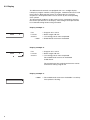
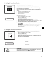
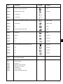
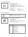
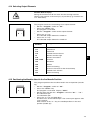
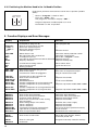
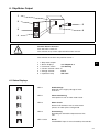
743 - 221
Sewing unit for the automated sewing
single-point darts with straight
or curved seam form
and for the sewing of pleats.
Instructions for operating
1
Installing Instruction
2
Instructions for service
3
Instructions for programming
4
Postfach 17 03 51, D-33703 Bielefeld • Potsdamer Straße 190, D-33719 Bielefeld
Telefon (05 21) 9 25-0 • Telefax (05 21) 9 25 24 35
Anleitung, komplett
Manual, complete
743 - 221
Inhalt
Summary
Bedienungstafel
Operating table
Bedienanleitung
Aufstellanleitung
Serviceanleitung
Programmieranleitung
Instructions for operating
Installating instruction
Instructions for service
Instructions for programming
Bauschaltplan
Interconnection-diagramm
9870 743031 B
9870 743031 B
Stromlaufplan
Circuit-diagram
9850 743030 SK
9850 743030 SK
Pneumatik Geräteplan
Pneumatic circuit plan
0794 013225
0797 743012
0794 013225
0797 743012
Postfach 17 03 51, D-33703 Bielefeld • Potsdamer Straße 190, D-33719 Bielefeld
Telefon: + 49 (0) 5 21 / 9 25-00 • Telefax: + 49 (0) 5 21 / 9 25 24 35 • www.duerkopp-adler.com Sprache: Deutsch/Englisch
Ausgabe / Edition:
03/01
Printed in Federal Republic of Germany
Teile-/ Part.-No.: 0791 743061
Foreword
This instruction manual is intended to help the user to become familiar
with the machine and take advantage of its application possibilities in
accordance with the recommendations.
The instruction manual contains important information on how to
operate the machine securely, properly and economically. Observation
of the instructions eliminates danger, reduces costs for repair and
down-times, and increases the reliability and life of the machine.
The instruction manual is intended to complement existing national
accident prevention and environment protection regulations.
The instruction manual must always be available at the machine/sewing
unit.
The instruction manual must be read and applied by any person that is
authorized to work on the machine/sewing unit. This means:
–
–
–
Operation, including equipping, troubleshooting during the work
cycle, removing of fabric waste,
Service (maintenance, inspection, repair) and/or
Transport.
The user also has to assure that only authorized personnel work on the
machine.
The user is obliged to check the machine at least once per shift for
apparent damages and to immediatly report any changes (including the
performance in service), which impair the safety.
The user company must ensure that the machine is only operated in
perfect working order.
Never remove or disable any safety devices.
If safety devices need to be removed for equipping, repairing or
maintaining, the safety devices must be remounted directly after
completion of the maintenance and repair work.
Unauthorized modification of the machine rules out liability of the
manufacturer for damage resulting from this.
Observe all safety and danger recommendations on the machine/unit!
The yellow-and-black striped surfaces designate permanend danger
areas, eg danger of squashing, cutting, shearing or collision.
Besides the recommendations in this instruction manual also observe
the general safety and accident prevention regulations!
General safety instructions
The non-observance of the following safety instructions can cause
bodily injuries or damages to the machine.
1. The machine must only be commissioned in full knowledge of the
instruction book and operated by persons with appropriate training.
2. Before putting into service also read the safety rules and
instructions of the motor supplier.
3. The machine must be used only for the purpose intended. Use of
the machine without the safety devices is not permitted. Observe all
the relevant safety regulations.
4. When gauge parts are exchanged (e.g. needle, presser foot, needle
plate, feed dog and bobbin) when threading, when the workplace is
left, and during service work, the machine must be disconnected
from the mains by switching off the master switch or disconnecting
the mains plug.
5. Daily servicing work must be carried out only by appropriately
trained persons.
6. Repairs, conversion and special maintenance work must only be
carried out by technicians or persons with appropriate training.
7. For service or repair work on pneumatic systems, disconnect the
machine from the compressed air supply system (max. 7-10 bar).
Before disconnecting, reduce the pressure of the maintenance unit.
Exceptions to this are only adjustments and functions checks made
by appropriately trained technicians.
8. Work on the electrical equipment must be carried out only by
electricians or appropriately trained persons.
9. Work on parts and systems under electric current is not permitted,
except as specified in regulations DIN VDE 0105.
10. Conversion or changes to the machine must be authorized by us
and made only in adherence to all safety regulations.
11. For repairs, only replacement parts approved by us must be used.
12. Commissioning of the sewing head is prohibited until such time as
the entire sewing unit is found to comply with EC directives.
13. The line cord should be equipped with a country-specific mains
plug. This work must be carried out by appropriately trained
technicians (see paragraph 8).
It is absolutely necessary to respect the safety
instructions marked by these signs.
Danger of bodily injuries !
Please note also the general safety instructions.
Contents
Page:
Part 4: Instructions for programming DA Microcontrol Cl. 743-221
. Program version: 743221A3
1.
General . . . . . . . . . . . . . . . . . . . . . . . . . . . . . . . . . . . . . . . . . . . . . . . . .
3
2.
2.1
2.2
2.3
Description of the Controls
Operator Controls on the Front Panel . . . . . . . . . . . . . . . . . . . . . . . . . . . . . . . .
Operator Controls at the Controls . . . . . . . . . . . . . . . . . . . . . . . . . . . . . . . . . .
Display . . . . . . . . . . . . . . . . . . . . . . . . . . . . . . . . . . . . . . . . . . . . . . . . .
4
5
6
3.
3.1
3.2
3.3
3.4
3.5
3.6
3.7
3.8
3.9
3.10
3.11
Description of the Function Keys
Selecting and Adjusting the Seam Length . .
Controlling the Seam Length via Light Barrier
Programming Mode . . . . . . . . . . . . . .
Setting Parameter Values . . . . . . . . . . .
Setting the Counter . . . . . . . . . . . . . .
Softstart . . . . . . . . . . . . . . . . . . . . .
Securing at the Seam Beginning . . . . . . .
Securing at the Seam End . . . . . . . . . .
Activating Securing . . . . . . . . . . . . . .
Smoother . . . . . . . . . . . . . . . . . . . .
Blower . . . . . . . . . . . . . . . . . . . . . .
.
.
.
.
.
.
.
.
.
.
.
.
.
.
.
.
.
.
.
.
.
.
.
.
.
.
.
.
.
.
.
.
.
.
.
.
.
.
.
.
.
.
.
.
.
.
.
.
.
.
.
.
.
.
.
.
.
.
.
.
.
.
.
.
.
.
.
.
.
.
.
.
.
.
.
.
.
.
.
.
.
.
.
.
.
.
.
.
.
.
.
.
.
.
.
.
.
.
.
.
.
.
.
.
.
.
.
.
.
.
.
.
.
.
.
.
.
.
.
.
.
.
.
.
.
.
.
.
.
.
.
.
.
.
.
.
.
.
.
.
.
.
.
.
.
.
.
.
.
.
.
.
.
.
.
.
.
.
.
.
.
.
.
.
.
.
.
.
.
.
.
.
.
.
.
.
.
.
.
.
.
.
.
.
.
.
.
.
.
.
.
.
.
.
.
.
.
.
.
.
.
.
.
.
.
.
.
.
.
.
.
.
.
.
.
.
.
.
.
.
.
.
.
.
.
.
.
.
.
.
.
.
.
.
.
.
.
.
.
.
.
.
7
7
7
8
8
8
8
9
9
9
9
4.
4.1
4.2
4.3
4.4
4.5
4.6
4.7
4.8
4.9
4.10
4.11
4.12
4.13
4.14
4.15
4.16
Setting the Sewing and Testing Programs
Display of the Program Version . . . . . . . . . . . . . . .
Sewing Program for Darts and Pleats . . . . . . . . . . .
Setting the Blower Activation Period . . . . . . . . . . . .
Setting the Underthread Counter . . . . . . . . . . . . . .
Setting the Remaining Thread Monitor . . . . . . . . . . .
Stopping Point for the Function Sequence . . . . . . . .
Monitoring the Underthread Counter . . . . . . . . . . . .
Test of the Step Motor Drive Pulse . . . . . . . . . . . . .
Timer Test and Memory Test . . . . . . . . . . . . . . . .
Continuity Test . . . . . . . . . . . . . . . . . . . . . . . .
Test of the Front Panel Elements . . . . . . . . . . . . . .
Checking the Input Elements . . . . . . . . . . . . . . . .
Selecting Input Elements . . . . . . . . . . . . . . . . . .
Selecting Output Elements . . . . . . . . . . . . . . . . .
Positioning the Machine Head in the 2nd Needle Position
Positioning the Machine Head in the 1st Needle Position
.
.
.
.
.
.
.
.
.
.
.
.
.
.
.
.
.
.
.
.
.
.
.
.
.
.
.
.
.
.
.
.
.
.
.
.
.
.
.
.
.
.
.
.
.
.
.
.
.
.
.
.
.
.
.
.
.
.
.
.
.
.
.
.
.
.
.
.
.
.
.
.
.
.
.
.
.
.
.
.
.
.
.
.
.
.
.
.
.
.
.
.
.
.
.
.
.
.
.
.
.
.
.
.
.
.
.
.
.
.
.
.
.
.
.
.
.
.
.
.
.
.
.
.
.
.
.
.
.
.
.
.
.
.
.
.
.
.
.
.
.
.
.
.
.
.
.
.
.
.
.
.
.
.
.
.
.
.
.
.
.
.
.
.
.
.
.
.
.
.
.
.
.
.
.
.
.
.
.
.
.
.
.
.
.
.
.
.
.
.
.
.
.
.
.
.
.
.
.
.
.
.
.
.
.
.
.
.
.
.
.
.
.
.
.
.
.
.
.
.
.
.
.
.
.
.
.
.
.
.
.
.
.
.
.
.
.
.
.
.
.
.
.
.
.
.
.
.
.
.
.
.
.
.
.
.
.
.
.
.
.
.
.
.
.
.
.
.
.
.
.
.
.
.
.
.
.
.
.
.
.
.
.
.
.
.
.
.
.
.
.
.
.
.
.
.
.
.
.
.
.
.
.
.
.
.
.
.
.
.
.
.
.
.
.
.
.
.
.
.
.
.
.
.
.
.
.
.
.
.
.
.
.
.
.
.
10
11
12
13
13
14
14
15
15
16
16
18
18
19
19
20
5.
Function Displays and Error Messages . . . . . . . . . . . . . . . . . . . . . . . . . . . . . .
20
6.
6.1
Step Motor Output . . . . . . . . . . . . . . . . . . . . . . . . . . . . . . . . . . . . . . . . . .
Status Displays . . . . . . . . . . . . . . . . . . . . . . . . . . . . . . . . . . . . . . . . . . . . .
21
21
.
.
.
.
.
.
.
.
.
.
.
.
.
.
.
.
.
.
.
.
.
.
.
.
.
.
.
.
.
.
.
.
.
.
.
.
.
.
.
.
.
.
.
.
.
.
.
.
.
.
.
.
.
.
.
.
.
.
.
.
.
.
.
.
.
.
4
1. General
The MICROCONTROL controls of the DÜRKOPP ADLER 743-221
include the integrated comprehensive MULTITEST testing and
monitoring system.
A microcomputer assumes the control tasks, monitors the sewing
process and signals operating faults and malfunctions.
Special programs facilitate mechanical adjustments and make
possible a rapid testing of the input and output elements without
additional measuring apparatus.
Errors and test results are shown in a 2 x 16 digit display.
Under normal working conditions the display shows information to
operation and the sewing process.
When an operating error or malfunction occurs the functions are
interrupted. The cause is shown in the display by the appropriate error
symbol. In most cases the error symbol will disappear when the cause
of the fault has been remedied.
In some cases the main switch must be turned off during error
correction for safety reasons.
A portion of the error messages are meant only for the service
personnel.
All functions can be called up and changed by pressing the
appropriate key. The unit must be in its initial position for this.
When the unit is switched on the controls conduct several
comprehensive self-tests. Among other things the program and data
memories and the display are checked for flawless operation at this
time.
After the machine is switched off the set values of the individual
functions are stored in the program and data memories (battery
buffered) and automatically activated when switched on again.
4
3
2. Description of the Controls
2.1 Operator Controls on the Front Panel
Key
Function
Key
Function
Selecting sewing and testing programs
Stopping the current program,
Activating the selected program
Seam length L1
- Reserve -
Seam length L2
- Reserve -
Seam length L3
Softstart
Seam length via light barrier
Stitch condensation seam
beginning
Seam bar tacking seam beginning
Programming ON / OFF
Stitch condensation seam end
Seam bar tacking seam end
Stitch condensation or bar tack:
Increase the parameter value
Seam
Seam
Seam
Seam
beginning
beginning
beginning
beginning
with
without
with
without
Seam
Seam
Seam
Seam
Decrease the parameter value
Smoother
Setting the counter, Starting the test
program, Confirming and selecting
parameters
4
Blower from above
Blower from the right
end
end
end
end
with
with
without
without
2.2 Operator Controls at the Controls
The needle- and underthread monitors are activated with the DIP
switch b417 at the controls.
The dials b401 and b402 have no function.
Caution Electric Current !
The switches may only be altered with the main switch turned off.
ATTENTION !
The switches are only verified once after the sewing unit is turned on.
After changing the switch setting turn the main switch off and on again
or operate the " STOP " key.
DIP switch
b417
Dials
b401
b402
4
DIP switch
b417
1
2
3
4
5
6
7
8
open
- Reserve Needle thread monitor active
- Reserve - Reserve Underthread monitor not active
- Reserve - Reserve - Reserve -
Dial b401
0...9 = no function
Dial b402
0...9 = no function
closed
-Reserve Needle thread monitor not active
- Reserve - Reserve Underthread monitor active
- Reserve - Reserve - Reserve -
5
2.3 Display
The Microcontrol controls are equipped with a 2 x 16 digit display.
It displays program number, sewing lengths, underthread reserve and
piece counts. With operator errors or malfunctions the function
sequence is interrupted and the cause shown by the corresponding
error symbol.
The operational readiness of the sewing unit is signaled by showing
the current parameters in the display. The settings correspond to the
last selected setting before being turned off.
Display example 1:
P15
L2=150
Σ=0174
= 1043
=
=
=
=
Program 15 is active
Seam length 150 mm
174 sewing pieces were completed.
Underthread reserve on the bobbin
Display example 2:
P15
L2=150
Σ=0174
= Program 15 is active
= Seam length 150 mm
= 174 sewing pieces were completed.
The underthread reserve on the bobbin
is not shown.
The monitoring of the underthread counter can be
turned on or off by program 44.
Display example 3:
= 0000
6
= The underthread reserve on the bobbin is used up.
The symbol is flashing.
3. Description of the Function Keys
3.1 Selecting and Adjusting the Seam Length
Three stored seam lengths can be selected via the L1, L2 and L3
keys. A change in the seam length can only be made before starting
the feed procedure.
– Select the stored seam length by pressing the L1, L2 or L3 key.
The selected seam length is shown in the right half of the first line
of the display.
– If "L?" appears in the display a seam length was selected under
which no valid value is stored.
Enter a valid value via the " + " or " - " key or select another seam
length.
– Change the set seam length with the " + " or " - " key.
– Press the function key (L1, L2 or L3).
The set seam length is stored.
It remains in the memory until it is changed again.
3.2 Controlling the Seam Length via Light Barrier
The light barrier is turned on by pressing this key.
The light barrier recognizes the end of the cloth.
– Press the key.
The symbol "LX" appears in the display in place of the seam
lengths L1, L2, L3.
– To turn off the light barrier press one of the L1, L2 or L3 keys.
4
3.3 Programming Mode
The programming mode is activated by pressing this key.
– Press the " P " key for 3 seconds.
The program position and the values to be changed appear in the
display.
With the " Σ " key the individual, alterable parameters are called
up consecutively.
– Press the " P " key.
The programming mode is ended.
The sewing unit is ready for sewing.
7
3.4 Setting Parameter Values
The set parameter values / seam lengthsare changed via the
" + " or " - " key.
– Press the " + " key.
The parameter value / seam lengthsis increased.
– Press the " - " key.
The parameter value / seam lengthsis decreased.
– Only in program 41 !
Press the " + " and " - " keys at the same time.
The initial value for the underthread reserve is reset to 0000.
ATTENTION !
By setting the initial value to 0000, the underthread monitoring is
turned off and the automatic remaining thread monitor is activated
at the same time.
3.5 Setting the Counter
The piece counter shows the number of finished sewing pieces since
the last resetting of the counter.
The current piece count appears in the left half of the lower line of the
display.
– Press the " Σ " key.
The piece counter is reset to 0000.
In the programming mode the parameter value is confirmed and one
moves to the next parameter with the " Σ " key.
In the testing programs the corresponding action is started with the
" Σ " key.
3.6 Softstart
The Softstart is activated by pressing this key.
With Softstart, sewing occurs at a low speed at the beginning of the
sewing sequence and then accelerates to the sewing speed.
– Press the key.
The Softstart is activated. The LED is lit.
– Press the key.
The Softstart is deactivated. The LED is off.
3.7 Securing at the Seam Beginning
End securing at the seam beginning is selected by pressing this key.
The end securing is only conducted if it is activated with the "
" key.
–
–
8
Press the key.
End securing through stitch condensation is selected.
The LED is lit.
Press the key.
End securing through seam bar tacking is selected.
The LED is off.
3.8 Securing at the Seam End
End securing at the seam end is selected by pressing this key.
The end securing is only conducted if it is activated with the "
–
–
" key.
Press the key.
Securing through stitch condensation is selected.
The LED is lit.
Press the key.
Securing through seam bar tacking is selected.
The LED is off.
3.9 Securing Activation
The selected securing at the seam beginning or at the seam end is
activated by pressing this key.
– Press the key.
Dependent on which LEDs are lit that securing is active.
Securing through stitch condensation or bar tack:
Seam beginning with
Seam
Seam beginning without
Seam
Seam beginning with
Seam
Seam beginning without
Seam
end
end
end
end
with
with
without
without
4
3.10 Smoother
The smoother is activated by pressing this key.
– Press the key.
The smoother is activated. The LED is lit.
– Press the key.
The smoother is deactivated. The LED is off.
3.11 Blower
One selects if the sewing piece is blown out from above or from the
right by pressing this key.
The corresponding blower device must be installed.
– Press the key.
Depending on which LEDs are lit the blower from above or from
the right is active or the blowing is turned off.
Blower from above
Blower from the right
Blower turned off
9
4. Setting the Sewing and Testing Programs
The sewing and testing programs are selected with the " Program "
selection switch.
– Set the " Program " switch to the desired program.
– " Turn the main switch on " or press the " STOP " key.
The selected program is activated.
–
If the " P? " message appears, an invalid program was set.
(Exception in program 43. See there)
Correct the setting and press the " STOP " key.
" Program "
Switch
00
10 - 29
40
41
42
43
44
57
59
60
61
62
63
64
66
67
Function
Display of the program version
Sewing program for darts and pleats.
Setting the blower activation period
Setting the underthread counter
Setting the remaining thread monitor
Stopping point for the function sequence
Monitoring the underthread counter
Test of the step motor drive pulse
Timer test and memory test
Continuity test
Test of the front panel elements
Test of the input elements
Selecting input elements
Selecting output elements
Sewing drive: nominal value X,, pos. 2
Sewing drive: nominal value X,, pos. 1
4.1 Display of the Program Version
The program version and a checksum appear in the display.
e.g.: 743221A1 743221 = Class designation
A1
= Identification letter and serial number
By program versions with identical class designation and identical
identification letters the higher version replaces all lower versions
( e.g.: 743221A3 replaces 743221A1 and 743221A2 ).
The checksum is meant only for the works service department. With
this value it is verified if the program memory faultlessly contains the
complete machine program.
– Set the " Program " switch to " 00 ".
– Press the " STOP " key.
The program is activated.
10
4.2 Sewing Program for Darts
The program positions 10 ...29 are available for free programming of
darts and pleats.
The programming mode is activated by pressing the " P " key for
minimum 3 seconds.
The value shown is changed with the " + " and " - " keys.
The value is immediately saved in nonvolatile memory.
The next program step is called up with the " Σ " key.
At the last program step the return to the 1st program step occurs by
pressing the " Σ " key.
The programming mode is exited by pressing the " P " key.
Example:
Program position 10 is programmed.
–
–
Set the " Program " switch to 10.
" Turn the main switch on " or press the " STOP " key.
Program 10 is activated.
The sewing unit requests a reference run.
–
Press the " Σ " key.
The reference run is conducted.
–
Press the " + " and " - " keys at the same time.
The piece counter is reset to 0000.
–
Press the " P " key for 3 seconds.
The programming mode is activated.
Set the rpm for sewing.
Setting range: 3800 - 4800 min -1 Resolution: 100 min -1
–
Press the " Σ " key.
Set the rpm for bar tacking at the seam beginning.
Setting range: 1000 - 3000 min -1 Resolution: 100 min -1
–
Press the " Σ " key.
Set the rpm for bar tacking at the seam end.
Setting range: 1000 - 3000 min -1 Resolution: 100 min -1
–
Press the " Σ " key.
Set the rpm for the advance.
Setting range: 3000 - 4000 min -1 Resolution: 100 min -1
–
Press the " Σ " key.
Rpm for thread chain.
This value can not be changed !
Setting range: 1000 min -1
–
Press the " Σ " key.
Set the rpm for Softstart.
Setting range: 200 - 1000 min -1 Resolution: 100 min -1
–
Press the " Σ " key.
Set the number of stitches for the advance.
Setting range: 0 - 20 stitches Resolution: 1 stitch
4
11
–
Press the " Σ " key.
Set the number of stitches for stitch condensation at the seam
beginning.
Setting range: 3 - 8 stitches
Resolution: 1 stitch
–
Press the " Σ " key.
Set the number of stitches for stitch condensation at the seam end.
Setting range: 3 - 8 stitches
Resolution: 1 stitch
–
Press the " Σ " key.
Set the number of stitches for bar tacking at the seam beginning.
Setting range: 3 - 5 stitches
Resolution: 1 stitch
–
Press the " Σ " key.
Set the number of stitches for bar tacking at the seam end.
Setting range: 3 - 5 stitches
Resolution: 1 stitch
–
Press the " Σ " key.
Set the number of stitches for the thread chain.
Setting range: 1 - 6 stitches
Resolution: 1 stitch
–
Press the " Σ " key.
Set the stitch length for stitch condensation.
Setting range: 0.5 - 1.4 mm Resolution: 0.3 mm
–
Press the " Σ " key.
Set the stitch length for sewing.
Setting range: 1.9 - 2.8 mm Resolution: 0.3 mm
–
Press the " Σ " key.
Set the time left anti-remover
Setting range: 1 (100 ms) - 9 (900 ms)
–
Press the " Σ " key.
Set the pulse length anti-remover
Setting range: 1 (100 ms) - 9 (900 ms)
–
Press the " P " key.
The programming mode is ended.
4.3 Setting the Blower Activation Period
The blower activation period for the blowing out of the sewing piece is
set in program 40.
– Set the " Program " switch to " 40 ".
– Press the " STOP " key.
The program is activated. The blower activation period appears.
– Set the desired value with the " + " or " —" key.
Setting range: 01...20 = 0.1...2.0 seconds
12
4.4 Setting the Underthread Counter
The underthread counter is set in program 41.
The presetable decrementer monitors the underthread reserve.
The decrementer works with the factor 10, this means, after every 10th
stitch the preset value is decreased by 1. This is shown in the right
half of the lower line of the display.
The size of the initial value to be selected depends on the following
factors:
– Thickness of the underthread used
– Thread tension during winding
– Material thickness
Setting the initial value
– Set the " Program " switch to " 41 ".
– Press the " STOP " key.
The program is activated.
The preset value appears in the lower line of the display.
The current position to be changed blinks.
– Set the desired value for each position with the " + " or the " - " key.
– The next higher position is selected with the " Σ " key.
– By operating the " + " and " - " keys at the same time the counter is
reset to 0000.
ATTENTION !
By setting the value to 0000 the underthread monitoring through
the counter is turned off and the automatic remaining thread
monitor activated.
4
4.5 Setting the Remaining Thread Monitor
Program 42 serves for the alignment of the reflected light barrier.
– Set the " Program " switch to " 42 ".
– Press the " STOP " key.
The program is activated.
With correct alignment of the light barrier a reflection occurs with
the turning of an empty bobbin.
Reflexion
No reflexion
ATTENTION !
The remaining thread monitor is only effective when the value for the
underthread counter was set to 0000 in program 41.
13
4.6 Stopping Point for the Function Sequence
A sewing program with stopping points is run through in program 43.
– Set the " Program " switch to " 43 ".
– Press the " STOP " key.
The sewing unit requests a reference run.
– Press the " Σ " key.
The reference run is conducted.
–
–
–
The display P? appears.
Set the " Program " switch to the sewing program to be sewn with
this testing program.
Insert the table manually.
The form set closes automatically.
Press the " Σ " key.
The table runs back into the initial position.
Check if the material was precisely transfered and is sufficiently
clamped.
–
Press the " Σ " key.
The sewing sequence is started and runs to the point where the
the thread shears are up.
Check if the thread lies under the shears.
–
Press the " Σ " key.
The needle and the underthreads are trimmed.
Check if both threads were trimmed cleanly.
–
Press the " Σ " key.
The form set opens and is run into the right end position.
The program sequence can be started again.
4.7 Monitoring the Underthread counter
The monitoring of the underthread counter is turned on or off by
program 44.
– Set the " Program " switch to " 44 ".
– Press the " STOP " key.
The program is activated.
– Press the " Σ " key.
The monitoring of the underthread counter is turned on or off.
14
4.8 Test of the Step Motor Drive Pulse
Program 57 checks the step motor controller and the outputs of the
step motor.
– Set the " Program " switch to " 57 ".
– Press the " STOP " key.
The testing program is activated.
The results appear.
Display
AMP ERR
LINK OK
LINK ERR
EPROM OK
EPRO ERR
XCOU OK
XCOU ERR
SCOU OK
SCOU ERR
Explanation
Error in the output or transmission cable
not plugged in
Transmission to the controller OK
Error in the transmission
EPROM OK
EPROM defective
Counter component for cycle counting OK
Counter component for cycle counting defective
Counter component for cycle generation OK
Counter component for cycle generation defective
4.9 Timer Test and Memory Test
ATTENTION !
This program erases all stored values.
Sewing lengths, blower activation period and all other values must be
reset.
The working memory and the timer switchings are checked by the
program independently.
– Set the " Program " switch to " 59 ".
– Press the " STOP " key.
The program is activated.
Display
Explanation
OK
ERROR 0
ERROR 6
ERROR 7
Working memory and timer are OK
RAM error
Timer 1 defective
Timer 2 defective
15
4
4.10 Continuity Test
Program 60 checks if the 24 V current supply supplies current with the
output drivers turned off.
Then program 60 checks all existing output elements, the output driver
and the installation for continuity.
–
–
Set the " Program " switch to " 60 ".
Press the " STOP " key.
The program is activated.
Display
V?
S17
Explanation
Short circuit in the installation or an output driver
is defective.
Interruption in the output element S17, in its
installation or driver.
Continue the check at the next element
by pressing the " Σ " key.
4.11 Testing the Front Panel Elements
Program P61 tests the front panel elements.
–
–
–
–
Set the "Program" switch to "61".
Press the "STOP" key.
The program is activated.
Operate the selector switch on the front panel.
The current setting value of the operated selector switch appears
in the display.
Upon operation of a key on the front panel (Exception: STOP key)
the numbers associated with this switch (1, 2, 4 or 8) appear.
The LEDs on the front panel are selected via code numbers. The
short designations of the circuit diagram (1 - 8) serve as code
numbers.
The LEDs are switched on with the "Σ" key.
Switch
b417
b401
b402
b413/412
b416
16
Function
Designation
Function switch
- none - none Program switch
Stop (key 13)
PROGRAM
STOP
Key
Function
Symbol
Display
b814
Stitch condensation NA
LED
b815
Setting the counter
Display
b816
- Reserve -
b817
- Reserve -
b818
Blower from above / blower from the right
LED / LED
b819
Smoother
LED / LED
b820
A
LED
b821
Stitch condensation NE
LED
b822
Softstart
LED
b823
Minus
Display
b824
Plus
Display
b825
P
display
b826
Seam length through light barrier
Display
b827
L3
Display
b828
L2
Display
b829
L1
Display
LED
Function display
H1b
H2
H3c
H4c
H5b
H6b
H7a
H8a
Stitch condensation NA
Securing NA
Softstart
Blower from the right
Blower from above
Smoother
Securing NE
Stitch condensation NE
4
17
4.12 Checking the Input Elements
Program 62 checks the input elements.
– Set the "Program" switch to "62".
– Press the "STOP" key. The program is activated.
– Press the input element.
The wiring diagram designation and the switching status of the
input element appear in the display (e.g. "+B25").
The display changes when the switching status of any other input
element is changed.
The switching status "+" means:
– By contact switch
– By proximity switch
– By reflecting light barrier
– Transmitted light barrier
=
=
=
=
Open contact
Metal in front of the switch
No reflection
Light beam not interrupted
4.13 Selecting Input Elements
ATTENTION !
All input elements were carefully set at the factory.
The resetting and correction may only be conducted by trained service
personnel.
Program 63 is used for setting the input elements.
– Set the " Program " switch to " 63 ".
– Press the " STOP " key.
The program is activated.
– Set the " Program " switch to the selected input element (see
Table).
– Adjust the input element (switching flag, switching cam, etc.) until
the desired switching status appear.
18
Input
Element
Function
b03
b04
b05
b07
b12
b14
b15
b16
b45
b46
Table forward
Sewing enabled
Transport carriage left
Transport carriage right
knee-switch
Needle thread monitor
Form set slewing
Form set control
Light barrier seam end
Remaining thread monitor
4.14 Selecting Output Elements
Caution Risk of Injury !
During the function test do not reach into the running machine.
Choose your position so that no injury is possible (e.g. Function test
s17: Table back).
The program checks the functioning of an output element.
– Set the " Program " switch to " 64 ".
– Press the " STOP " key.
The program is activated.
– Set the " Program " switch to the output element.
– Press the " Σ " key.
The selected output element is turned on.
– Press the " Σ " key.
The selected output element is turned off.
Output
Element
Designation
s17
s18
s19
s9
s10
s20 / s20A
s25
s28
s29
s30
s31
s32
Table back
Table free
Thread tension release
Blower from the right
Blower from above
Vacuum
Smoother
Shears
Form set slewing
Pressure increase for the thread clamp
Thread chain release
Form set closing
4
4.15 Positioning the Machine Head in the 2nd Needle Position
This program positions the machine head in the 2nd position (needle
up).
– Set the " Program " switch to " 66 ".
– Press the " STOP " key.
The program is activated. Display " SW? "
– Set the drive rpm with the " Program " switch to " 01 "... " 13 ".
01 = Minimum rpm
13 = Maximum rpm
– Press the " Σ " key and hold down.
The drive runs at the selected rpm. The current rpm appears after
a few seconds.
After release of the " Σ " key, the needle positions in the 2nd
position (needle up).
19
4.16 Positioning the Machine Head in the 1st Needle Position
Program 67 positions the machine head in the 1st position (needle
down).
– Set the " Program " switch to " 67 ".
– Press the " STOP " key.
The program is activated. Display " SW? "
Program sequence and description as in 4.15.
Positioned is in the 1st position.
5. Function Displays and Error Messages
Display
P?
743221A1
---REF--->
REF--->
---x---
Explanation
Invalid program
(Exception in program 43)
Display of the program version
Run to the reference point
Run to the reference point
Thread breakage
POS-ERR
--( )-SW?
E2
STOP
Check the motor protection switch
Motor doesn’t turn
Check the synchronizer
No signal from the synchronizer
Reset the " Program " switch
Invalid rpm level set
Fuse E2 on the control transformer defective Replace the fuse
Replace the Stop key
Stop key defective
b417
b16
b4
SMC TEST
AMP ERR
Invalid switch setting at b417
Form set not present
Sewing enabled
Step motor controller being tested
Error in the output
Transmission cable not plugged in
Reset switch b417
Insert the form set
----See notes to step motor output
Plug in transmission cable
LINK OK
LINK ERR
EPROM OK
EPRO ERR
XCOU OK
XCOU ERR
Transmission to the controller OK
Error in the transmission
EPROM OK
EPROM defective
Counter component for cycle counting OK
Counter component for cycle counting
defective
Counter component for cycle generation OK
Counter component for cycle generation
defective
RAM error
Error in the input elements
Error in the front panel elements
Program switch defective
Error in the transmission to the sewing
drive regulator
Short voltage drops in the mains
Timer 1 defective
Timer 2 defective
Transport carriage left (end position)
Light barrier (no material present)
Error in input element Bxx
--Replace the controls
--Install a new EPROM
--Replace step motor modul 9850 745007
PROG
ERROR 1
Error in the saved values
Reset the seam lengths, blower
activation period, etc.
PROG
ERROR 2
Error in saving the
checksum
Program incorrectly stored in memory
SCOU OK
SCOU ERR
ERROR
ERROR
ERROR
ERROR
ERROR
0
1
2
3
4
ERROR 5
ERROR 6
ERROR 7
ERROR B5
ERROR B45
Error Bxx
20
Remarks
Reset the " Program " switch
(See program 43)
------Reinsert thread
--Replace step motor modul 9850 745007
Replace the controls
Check the input elements
Check the front panel elements
Replace the program switch
Replace the controls
Stabilize the current supply
Replace the controls
Replace the controls
Push into the base position manually
Insert material
Bxx defective or incorrectly set
6. Step Motor Output
1
2
5
3
6
4
Caution Electric Current !
Turn the main switch off !
The switches may not be adjusted while under current.
The switches must be in the position shown !
1
2
3
4
5
6
=
=
=
=
=
=
Step motor output
Status displays
Parameter switch
Current selector switch
Voltage selector
Operation lamp
4
see Chapter 6.2
see drawing
F
230 V
ON / OFF
6.1 Status Displays
LED 1
Undervoltage
Shortfall in the supply voltage of more
than 30 %.
LED 2
Phase monitoring
Interruption in one or more motor leads.
LED 3
Short circuit
Short circuit between one or more motor
phases or motor phase and ground.
LED 4
Overheating
Exceding the allowable temperature of the
unit.
LED 1 and 2
Reset
The ENABLE input is not activated by the controls.
21