1
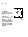
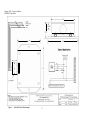
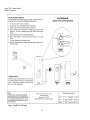
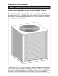
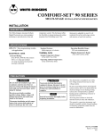
Model T9000 Wireless Thermostat
Installation and User Guide
ENERNET Corporation
Copyright ©2005
Table of Contents
INTRODUCTION............................................................................................................................................................................................................................1
MOUNTING ....................................................................................................................................................................................................................................2
INSTALLING/CHANGING BATTERIES....................................................................................................................................................................................2
Figure 1 — Battery Locations ......................................................................................................................................................................................................................... 2
Replacing same type batteries (Alkaline or Lithium).................................................................................................................................................................2
Figure 2 — Opening Thermostat..................................................................................................................................................................................................................... 2
FOUR-BUTTON / HOTEL CONFIGURATION ..........................................................................................................................................................................3
Figure 3 — Four-Button Cluster...................................................................................................................................................................................................................... 3
Figure 4 — Four-Button LCD Display............................................................................................................................................................................................................ 3
SEVEN-BUTTON CONFIGURATION .........................................................................................................................................................................................4
Figure 5 — Three-Button Cluster .................................................................................................................................................................................................................... 4
SETTING THE CLOCK ......................................................................................................................................................................................................................4
PROGRAMMING YOUR THERMOSTAT..................................................................................................................................................................................5
RUN BUTTON .................................................................................................................................................................................................................................6
CHANGING TEMPERTATURE WHILE RUNNING A PROGRAM .......................................................................................................................................6
IMPORTANT NOTE ..........................................................................................................................................................................................................................6
INSTALLING AND REMOVING NODES ...................................................................................................................................................................................7
The Linking Procedure ..............................................................................................................................................................................................................7
Installing Nodes .............................................................................................................................................................................................................................................. 7
Removing Nodes........................................................................................................................................................................................................................7
All Nodes Removal ......................................................................................................................................................................................................................................... 7
Setting Min/Max Set Point.........................................................................................................................................................................................................8
Figure 7 — Internal Button ............................................................................................................................................................................................................................. 8
TROUBLESHOOTING FAQ .........................................................................................................................................................................................................9
Figure 1 — PTAC RCN Connection Diagram ..................................................................................................................................................................................... 12
Figure 2 — J-Box RCN Electric Heat Example ................................................................................................................................................................................... 13
Figure 3 — J-Box RCN Fan Coil Example .......................................................................................................................................................................................... 14
Figure 4 — Plug RCN Fan Coil Example ............................................................................................................................................................................................ 15
January, 2005 – Operators Manual
ENERNET Corporation
ENERNET CORPORATION PROVIDES THIS PUBLICATION
“AS IS” WITHOUT WARRANTY OF ANY KIND, EITHER
EXPRESS OR IMPLIED, INCLUDING, BUT NOT LIMITED TO,
THE IMPLIED WARRANTIES OF MERCHANTABILITY OR
FITNESS FOR A PARTICULAR PURPOSE.
THIS MANUAL MAY CONTAIN TECHNICAL INACCURACIES
AND/OR TYPOGRAPHICAL ERRORS.
CHANGES ARE
PERIODICALLY MADE TO THIS MANUAL, WHICH ARE
INCORPORATED IN LATER EDITIONS.
ENERNET CORPORATION MAY MAKE CHANGES AND
IMPROVEMENTS TO THE PRODUCT(S) AND/OR PROGRAMS
DESCRIBED IN THIS PUBLICATION AT ANY TIME
WITHOUT NOTICE.
IN NO EVENT WILL ENERNET CORPORATION BE LIABLE
FOR DAMAGES, INCLUDING LOST PROFITS, LOST SAVINGS
OR OTHER INCIDENTAL OR CONSEQUENTIAL DAMAGES
ARISING OUT OF THE USE OF OR INABILITY TO USE SUCH
PRODUCT, EVEN IF ENERNET CORPORATION OR AN
APPROVED RESELLER HAS BEEN ADVISED OF THE
POSSIBILITY OF SUCH DAMAGES, OR FOR ANY CLAIM BY
ANY OTHER PARTY.
E N E R N E T
Corporation
307 Dewittshire Road, Syracuse, New York 13214
Phone: (315) 449-0839
Fax: (315) 449-3056
January, 2005 – Operators Manual
ENERNET Corporation
MODEL T9000 INSTALLATION AND USER GUIDE
INTRODUCTION
The T9000 is a two-part wireless thermostat system, designed to
provide precision temperature control without the installation
headaches and expense of wiring. Powered by four-AA batteries,
the thermostat will operate for approximately 1.5 years, and can
be mounted in any suitable location in the space that will ensure
good temperature control. A large LCD display provides the user
with current space temperature, set point temperature, time,
program interval, and other system status information. For hotel
room applications, programming, clock setup buttons and
associated display information are typically not provided. The
second part of The T9000 system is called a Remote Control
Node or RCN. An RCN interfaces with the desired HVAC
equipment, and communicates with its thermostat using
unlicensed 900MHz radio frequency energy. At the time of
installation, the T9000 thermostat can be linked to more than one
RCN. A thermostat and RCN that have been linked will not
interfere with or be affected by any other thermostat or RCN in
adjacent rooms, apartments, or neighboring homes.
Other RCNs
Baseboard
Heat
A unique feature of the T9000 is its ability to simultaneously
control completely unrelated heating and cooling equipment.
Baseboard heaters and window a/c is a good example. Available
RCN models allow these loads to be controlled by the same
thermostat. This unique capability creates a virtual central
heating and cooling control system.
T–9000
Thermostat
Window A/C
1
Hotel PTAC
Unit
January, 2005 – Operators Manual
ENERNET Corporation
(approximately 1.5 years can be expected). Batteries are paired in
sets of two - one set is side-by-side, the other end-to-end.
MOUNTING
Find a suitable location for mounting your thermostat, preferably
an interior wall, centrally located within the conditioned space at
about 5' above the floor. Try not to locate the thermostat in a
place where it could be exposed to heat such as a directly above a
reading lamp or in a place where it could be exposed to direct
sunlight. Such heat sources can affect temperature readings and
performance.
NOTE:
Battery orientation is critical.
Set B
STEP ONE:
Remove the base plate from the thermostat housing, using it to
mark locations for mounting holes (Fig. 2). We recommend you
use a small level across the top or one side of the base plate.
Set A
Set B
Set A
Thermostat PCB
Battery Pair B
(Positive terminal
points right)
Battery Pair A
(Positive terminal
points up)
Figure 1 — Battery Locations
Replacing same type batteries (Alkaline or Lithium)
STEP TWO:
Drill 3/8” holes and insert drywall fasteners and fasten the base
plate to the wall. After installing batteries (see below) carefully
snap the housing onto the base plate.
To open the thermostat, use both hands, press the two push-tabs on
the bottom of the thermostat housing with your thumbs while gently
pulling the bottom away from the base.
INSTALLING/CHANGING BATTERIES
The “Battery Low” or
icon will light on the thermostat
display when the thermostat batteries are within a week or two of
being exhausted. The T9000 is designed to accept either alkaline
or 1.5 volt lithium batteries such as the Energizer PHOTO L91
Lithium AA. Standard alkaline batteries such as Duracell AA
will perform well. The Energizer L91 lithium battery cost more
but will run the thermostat somewhat longer.
Front Cover
Base Plate
Push-tab
Latches
Figure 2 — Opening Thermostat
The T9000 operates with either 2 or 4 AA batteries. Four (4)
batteries will obviously double the time between battery changes
2
January, 2005 – Operators Manual
ENERNET Corporation
Do not mix battery types, use either all lithium or all alkaline. Do
not put new batteries in with an old pair. If you are replacing
batteries, replace them all.
FAN
HEAT
COOL
UP
DOWN
Figure 3 — Four-Button Cluster
When four (4) batteries are currently installed, remove either the
top two end-to-end pair or the side-by-side pair and replace them.
Next, remove the other pair and replace. This keeps power to the
thermostat at all times, maintaining your clock and program
settings.
FAN:
Switches from FAN AUTO, FAN 1 and FAN 2.
HEAT/COOL:
Switches between HEAT, COOL and OFF.
UP:
Moves the set point temperature UP.
If two batteries are currently installed, install two new batteries in
the empty battery holders, noting the + and – polarity. Next,
remove the old batteries. This replacement scheme also allows
the thermostat to continue running without losing any
programmed information or clock setting.
DOWN:
Moves the set point temperature DOWN.
In the four-button configuration model, the LCD display provides
space temperature, set point temperature, fan status, and operating
mode, heat, cool or off.
If replacing batteries with a different type (i.e., replacing Lithium
with Alkaline or Alkaline with Lithium) — Remove old batteries
and wait for the front display to go blank. Install new batteries,
reset the time and programs.
COOL
Current
Temperature
Mode of
Operation
O
FOUR-BUTTON / HOTEL CONFIGURATION
The T9000 can be ordered in a four or seven button configuration.
Typically in hotel applications, users do not need access to
programming or clock functions. Buttons for those functions are
therefore not provided in the hotel model. The four-button
control cluster consists of FAN, HEAT/COOL, UP and DOWN.
Setpoint
70 O
FAN AUTO
Fan Status
Figure 4 — Four-Button LCD Display
3
Setpoint
January, 2005 – Operators Manual
ENERNET Corporation
SEVEN-BUTTON CONFIGURATION
Setting the Clock
The seven-button T9000 thermostat provides programmable
functions. The user can set the clock and program the thermostat
to automatically set specified temperatures at specified times.
PROGRAM
RUN
As you adjust the clock and program your T9000, notice that the
display helps you by continuously blinking the item you are ready to
change. The UP and DOWN buttons change settings, the
HEAT/COOL button is used to ENTER or keep a change.
CLOCK
To set the clock, you will use the buttons marked CLOCK, UP,
DOWN, and HEAT/COOL.
Figure 5 — Three-Button Cluster
STEP ONE:
Press the CLOCK Button. The hour digits will flash. Press the UP
or DOWN button to change to the proper hour. Note that AM / PM
will change as you roll the hour past 12. Be sure to set the hour
properly for AM or PM. Press the HEAT/COOL button to keep the
hour you've just set and to move to minutes.
PROGRAM:
Places the T9000 into program mode.
RUN:
Causes the T9000 to run or stop running its program.
CLOCK:
Places the T9000 into clock setup mode.
Time & Day
Current
Temperature
STEP TWO:
The Minute digits will now be blinking. Press the UP or DOWN
button to change to the desired minute. When the correct minute is
flashing press HEAT/COOL.
Program Period
11:20
AM
Th
COOL
Day
Mode of
Operation
O
STEP THREE:
One of the seven day icons (Mo, Tu, We, Th, Fr, Sa, Su) will now
flash. Press UP or DOWN until you see the current day icon
flashing. When the correct day is flashing press HEAT/COOL.
Set Point
70 O
FAN AUTO
Setpoint
Fan Status
STEP FOUR
Figure 6 — Seven-Button LCD Display
Press the CLOCK button to keep all clock changes you've made
and resume normal operation.
4
January, 2005 – Operators Manual
ENERNET Corporation
PROGRAMMING YOUR THERMOSTAT
display is blinking the one you want to program.
HEAT/COOL.
Your T9000 provides you with four program periods: Morning,
Day, Evening, and Night. You can set the time and temperature
of each period, corresponding to the time you wake-up, leave for
the day, return home, and sleep. For example:
PERIOD
MORNING
DAY
EVENING
NIGHT
TIME
6:30 AM
8:30 AM
4:15 PM
11:30 PM
Press
STEP TWO:
The Morning period will be blinking. Use the UP or DOWN
button to toggle through Morning, Day, Evening, or Night,
stopping at the period you want. Press HEAT/COOL.
TEMP.
70°
64°
70°
60°
STEP THREE:
Next, the hour of the day will blink on the display. This is the
starting hour of the period you have selected. Use the UP or
DOWN button to change the selected hour start time. Press
HEAT/COOL.
The T9000 does not allow separate heating and cooling programs.
Whatever you program for times and temperatures will apply to
heating or cooling. Check the program when switching over from
heating to cooling and back. What is comfortable in the cooling
season may not be in the heating season. During summer months
for example, when air conditioning your home, an indoor air
temperature of 75º, or even warmer feels comfortable. However,
in the winter, 75º will likely feel too warm. You should check
your thermostat program seasonally and adjust as needed.
STEP FOUR:
The minute of the day will blink next. This is the starting minute
in the hour. Use the UP or DOWN button to change the minute
digits to the desired setting. (Note that minutes change in fiveminute increments.) Press HEAT/COOL.
STEP FIVE:
The desired set point will now be blinking. This is the temperature
you want the thermostat to bring the heated or cooled space to at
the time of day you have selected. Press the UP or DOWN button
to change the set point temperature to what you want. Press
HEAT/COOL.
To program your thermostat, you will use the PROGRAM,
HEAT/COOL, UP, and DOWN buttons.
STEP ONE:
Press the PROGRAM button to put the thermostat into the
programming mode. The display will blink all of the day of the
week icons. Pressing the UP or DOWN button will toggle
between (weekday) icons and the (weekend) icons. Ensure the
This completes the programming of the first period of the day.
5
January, 2005 – Operators Manual
ENERNET Corporation
buttons, and the thermostat will maintain the temperature you set
until you manually change it again.
STEP SIX:
If you started with the Morning time period, the next period,
Day, will now be blinking. Follow steps two, three, four, and five
for each period you wish to program.
CHANGING TEMPERTATURE WHILE RUNNING A
PROGRAM
NOTE:
You can leave the programming mode by pressing the
PROGRAM button anytime. You can skip to any programmable
choice you want to change. For example, you can change the set
point temperature for a period of the day by pressing the
PROGRAM button, and then HEAT/COOL until the first period
of the day “MORNING” is flashing. Using the UP or DOWN
button will move to other periods. When the period you want is
flashing, press the HEAT/COOL button until the “Set Point”
temperature is blinking. Adjust the set point using the UP or
DOWN button until the desired temperature is displayed. With
the change now made, press the PROGRAM button to leave the
program setup mode, storing the change and returning the
thermostat to normal operation.
Even when your thermostat is running in its program mode, you
can change the temperature to what you want just by using the UP
or DOWN buttons. However, when the program moves to the
next period, your thermostat will go to the programmed set point
temperature for the next period. For instance, assume the current
program period is Evening, with a programmed temperature of 70°
and the next period, which is Night, is programmed for 65°,
scheduled to start at 11pm. If during the Evening time period you
wanted it warmer, you could press the UP button and raise the
temperature to something above 70°. The thermostat will hold that
temperature until the next programmed period comes around, at
which point the temperature will adjust to whatever temperature is
programmed. In this case the Night period is set for 11pm, at
which time the thermostat's program will take over again and set
the temperature to 65°.
Run Button
The RUN button toggles the thermostat between manual
operating mode and programmed operating mode. When in the
programmed mode, your thermostat responds to the times and
temperatures programmed. You will know if the thermostat is
running its program because one of the four periods, Morning,
Day, Evening or Night will be displayed, telling you which
period the thermostat is currently in. When in the manual mode,
there will be no time period icon displayed. In manual, you can
adjust to the desired temperature using the UP and DOWN
Important Note
The T9000 does not communicate with its RCN(s) any more
frequently than it must. Because it runs on batteries, limiting how
often the system communicates conserves energy and extends
battery life. Keep this in mind if you experience a delay after
making a change before your heater or air conditioner responds.
6
January, 2005 – Operators Manual
ENERNET Corporation
Press the HEAT/COOL button when you have the icon you want.
At this point all selections have been made and nothing on the
display should be blinking. You are now ready to install a node.
Press the SW9, LINK button on the back of the thermostat printed
circuit board and within 5-seconds activate a service request on the
RCN you are installing by the following method:
INSTALLING AND REMOVING NODES
The Linking Procedure
Installing a thermostat and RCN so that they will communicate with
each other, “links” them together as an operational system. When an
RCN is linked to a thermostat, it will thereafter only respond to that
specific thermostat. In some cases a thermostat and RCN will be
pre-linked in pairs by the factory. If this is not the case or you are
replacing a thermostat or RCN, or adding another RCN to an existing
system, the following procedure is used:
Plug Node RCN: Apply power by plugging it in.
Refer to Figure 7 for button location. Press the SW4 button. The
Install Icon will flash - Press the UP button to toggle through the
following two Icon choices:
=
=
Apply power or press Service Pin Button PB1.*
PTAC RCN:
Apply power or press Service Pin Button PB1.
After a delay of a few seconds, a response of “good," or “bad” is
displayed. If bad, repeat the procedure. Press the SW4 button to
return to normal operation.
Installing Nodes
Install ……… Icon lighted
Remove ……... Icon lighted
J-Box RCN:
NOTE:
The J-Box RCN is a line-voltage device. Only a qualified technician
should open the enclosure to access PB1. All others should use the
power up method only.
Install an RCN
Remove ALL RCNs
Press HEAT/COOL to select. The node number digit will flash.
Use the UP button to set the node number you wish to install 0-7.
Removing Nodes
All Nodes Removal
Press the HEAT/COOL button to select the node number. The
HEAT and/or COOL icon will now flash in the upper right hand
corner of the display. Press the UP button to toggle through the
following three Icon choices:
HEAT ……… Icon lighted
= Install an RCN as heating only
COOL ……… Icon lighted
HEAT ……… Icon lighted
COOL
= Install an RCN as cooling only
Unlike installing a node(s), the procedure to remove a node removes
all nodes installed to the thermostat at once. You cannot remove a
single node.
Press the thermostat SW4 MODE button. The Install Icon will
flash. Press the UP button to toggle between Install and Remove.
Stop at Remove and press HEAT/COOL to select. The node number
will not blink because all RCN nodes are being removed. Press PB1
on the back of the thermostat board.
= Install an RCN as heating & cooling
7
January, 2005 – Operators Manual
ENERNET Corporation
Thermostat PCB
No response will be displayed in this case. The thermostat is no
longer linked to any node. You can now install a new RCN, or press
the SW4 MODE button to return to the normal thermostat display.
SET B
SET B
SW9
LINK
Figure 7 — Internal Button
8
SET A
Micro
Set point minimums and maximums may be set on the T9000 to limit
the maximum heating set point and minimum cooling set point. To
enter the min/max setup mode, you must simultaneously press the
PROGRAM and RUN buttons. Note that on four-button model
thermostats these buttons are located inside, just below the side-byside "SET A" batteries (see Figure 7).
On seven-button
configuration models, these buttons are on the front of your
thermostat (see Figure 5). Simultaneously press the PROGRAM
and RUN buttons, the thermostat will display the HEAT icon and set
point temperature. Use the UP or DOWN buttons to set the
maximum heating set point you wish to allow. Next, press the
HEAT/COOL button to set the Max heating temperature and bring
up the COOL icon. With the COOL icon displayed, use the UP or
DOWN buttons to set the minimum cooling setpoint temperature
you wish to allow. Simultaneously pressing the PROGRAM and
RUN buttons will take you out of the Min/Max setup mode and store
the changes you've made.
SET A
PB1
Setting Min/Max Set Point
SW4
SW3
SW2
SW1
MODE
CLK
RUN
PGM
SW1 – SW3 are available
inside the thermostat on the
four-button hotel model.
January, 2005 – Operators Manual
ENERNET Corporation
TROUBLESHOOTING FAQ
“Where should I locate my thermostat?”
back on. Coincidental RF interference could be cause for a
temporary loss of communication. In virtually all such cases, the
interference is temporary. The thermostat will attempt to re-establish
communication with its RCN(s) within a maximum of ten minutes.
For best performance results, the thermostat should be located
approximately five feet above the floor on an inside wall in an area
with good air circulation. A thermostat should not be located where
air is stagnating such as behind doors, in corners or under cabinets.
Hot or cold drafts from air ducts and windows should be avoided.
Avoid heat from the sun, lighting fixtures, appliances, fireplaces, etc.
“What does the antenna symbol
(NOTE: If your T9000 uses the “RF Link Fail” message, it will be
displayed whenever the thermostat is unable to communicate with its
RCN(s).)
on the display mean?”
“I just installed the thermostat and the antenna
and goes. What should I do?”
The T9000 thermostat will display the
antenna icon as
long as it is able to communicate with its RCN(s). If after several
tries communication is not established, the antenna icon will turn off.
This may be caused by control node power being disconnected.
A weak RF signal between the thermostat and one or more RCN is
the cause of this. The further away the thermostat and RCN are from
each other, the weaker the signal becomes. The same weak signal
effect is caused when something is partially shielding or blocking the
T9000’s RF signal energy. Distance, particularly in residential
situations is typically not a problem. The most common cause for a
weak signal is sheet metal shielding the RCN. When installing,
choose a location that is not completely surrounded by sheet metal.
In some cases to overcome a weak signal problem, the RCN has to
be relocated or the thermostat moved closer to it. In rare cases where
the RCN can not be repositioned or where it is completely enclosed
in a sheet metal control box, a small section of sheet metal may need
to be removed and if necessary replaced with plastic.
(NOTE: Some T9000 displays use the “RF Link Fail” message in place of
the antenna symbol.
In this case, as long as the thermostat is
communicating with its RCN(s) there will be no symbols or messages to see.
The “RF Link Fail” message is the equivalent of losing the antenna
symbol.)
“What do I do if the antenna symbol
symbol comes
is no longer displayed?”
Check power to the equipment (i.e. Window a/c, baseboard heater,
fan coil unit). With power restored, force the thermostat to talk to
the RCN(s) by pushing the FAN button or running the set point
temperature above or below the room temperature (above in heating,
below in cooling). The thermostat will also automatically try to
communicate within a maximum of ten minutes from the last
attempt. If communication is successful the antenna icon will turn
(NOTE: Always consult with an HVAC contractor or manufacturer
before modifying any equipment electrically or structurally.)
9
January, 2005 – Operators Manual
ENERNET Corporation
“The display on my thermostat is blank. What happened?”
“If I am away for an extended time such as vacation, how do I set
the thermostat so my system does not run excessively?”
A blank display indicates that your batteries are depleted. When the
“Low Battery” or
icon is on, there is 1 or 2 weeks of
battery life remaining.
See the INSTALLING/CHANGING
BATTERIES section of this guide for information on how to change
the batteries. Keep in mind that if your thermostat loses battery
power, it no longer controls your heating/cooling system. We
recommend that when you change batteries, always use batteries that
you know are fresh. Use four (4) batteries for longest operation. If
you are using the T9000 to control a heating system, we recommend
putting fresh batteries in at the start of the heating season.
You have a couple of choices.
The first is to press the
HEAT/COOL button on the thermostat until the display reads
“OFF." (During the heating season, we do not recommend going to
the “OFF” mode.) The second option is to put your thermostat in
manual mode by pressing the RUN button. You know that you are
in the manual mode because none of the period icons, Morning,
Day, Evening, or Night will be showing (Refer to Figure 6). Next,
adjust the set point temperature to minimize system operation. For
example, you could adjust to a set point of 88° in cooling or 55° in
heating, staying mindful of what your temperature selection could
affect such as plants and animals that stay in your home while you
are away. During the cooling season, consider humidity as well as
indoor temperature. When your air conditioner runs it not only cools
the air, it also removes moisture, lowering humidity. High humidity
can encourage the growth of mold as well as other undesirable
effects.
“Can I run multiple heating or cooling loads such as electric
baseboard heating and a window air conditioner with one T9000
thermostat?”
Yes. In fact one T9000 thermostat can control up to eight (8)
different RCNs.
“Can I have a second thermostat controlling another load
without interference from my first thermostat?”
“How can I save energy with my T9000 thermostat system?”
The T9000 was designed to provide precision temperature control.
That alone can save energy since your system will be tightly
controlled to within a degree or two of your desired set point.
Studies have shown you can save up to 12% just through precision
temperature control.
Yes. A T9000 thermostat and its RCN(s) will talk between
themselves, but will never respond to another thermostat or
controller in adjacent rooms, apartments, or neighboring homes.
You can maximize savings if you also program your thermostat to
automatically turn the temperature up or down while you are away or
asleep. See the PROGRAMMING section of this guide for exact
details.
10
January, 2005 – Operators Manual
ENERNET Corporation
“What are the buttons inside my thermostat for?”
“I see solar cells on the T9000; does it need light to operate?”
Referring to Figure 7, the SW4 INSTALL button located at the
bottom center of the printed circuit board is used to put the
thermostat in the Install/Remove mode. The SW9 LINK button
located at the bottom far left of the circuit board and PB1 REMOVE
button above and to the right of SW9 are also used when installing or
removing an RCN from the thermostat. See the section entitled
INSTALLING AND REMOVING NODES. In many cases your
thermostat has come from the factory already linked to the control
node or a trained technician performed the linking procedure when
the T9000 was firsts installed. If you accidentally press the SW4
button and put the thermostat into the install mode, simply press it
again to put the thermostat back in normal operation. SW9 is only
used during installation. Pressing SW9 when not in the installation
mode has no effect. PB1 is only used when removing nodes that
have previously been linked to the thermostat.
When not reading temperature or communicating with an RCN, the
T9000 thermostat consumes very little power. Under some lighting
conditions, it will run off of the solar cells, even further extending
the lifetime of the batteries. While it’s a bad idea to let it get direct
sunlight, or be too close to a lamp, a well-lighted space is beneficial
to battery life.
“When my a/c turns off, I can’t immediately make it run again?”
This is normal. What you are experiencing is called an anti shortcycle delay. Because of high pressure in the system, it’s not a good
idea to start your air conditioner immediately after it has just shut
down. The T9000 automatically prevents this from happening by
imposing a delay of approximately 3-minutes.
(NOTE: Refer to the INSTALLING AND REMOVING NODES
section of this manual for detailed instructions. If you need
assistance installing or removing an RCN, contact your distributor
or call ENERNET Corporation for technical support.)
11
January, 2005 – Operators Manual
ENERNET Corporation
Figure 1 — PTAC RCN Connection Diagram
12
January, 2005 – Operators Manual
ENERNET Corporation
Figure 2 — J-Box RCN Electric Heat Example
13
January, 2005 – Operators Manual
ENERNET Corporation
Figure 3 — J-Box RCN Fan Coil Example
14
January, 2005 – Operators Manual
ENERNET Corporation
Figure 4 — Plug RCN Fan Coil Example
15