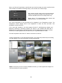
1
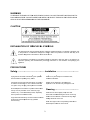
16 Channel Network Video Recorder
User’s Manual
English Version 0.98
Model :
NVR16 Series
www.atvideo.com
WARN
NING
TO RED
DUCE THE RISK
R
OF FIRE
E OR ELECT
TRIC SHOCK, DO NOT EXPOSE TH
HIS PROCUC
CT TO
RAIN OR
R MOISTUR
RE. DO NOT INSERT ANY
Y METALLIC
C OBJECT THROUGH TH
HE VENTILA
ATION
GRILLS OR OTHER
R OPENNING
GS ON THE EQUIPMENT
T.
TION
CAUT
ANATION OF GR
EXPLA
RAPHICA
AL SYMB
BOLS
The lightning flash with arrowhead syymbol, within an
a equilateral triangle, is intended to alerrt the user
nsulated "dangerous voltag
ge" within the product’s enclosure that may
m be of
to the presence of unin
m
to constitute
c
a rissk of electric shock.
s
sufficient magnitude
The exclamation point within
w
an equilateral trianglle is intended to alert the u
user to the prresence of
nd maintenancce (servicing)) instructions in the literatture accompa
anying the
important operating an
appliance.
PREC
CAUTION
NS
Safety
y ---------------------------------------- Installation -------------------------------Should an
ny liquid or so
olid object fall into
i
the cabine
et,
unplug the unit and havve it checked by the qualifie
ed
personne
el before opera
ating it any furrther.
ot install the unit
u in an extre
emely hot or hu
umid
Do no
place
e or in a place subject to exccessive dust,
mech
hanical vibratio
on.
Unplug th
he unit from th
he wall outlet iff it is not going
g to
be used for
f several dayys or more. To
o disconnect the
cord, pull it out by the plug.
p
Never pu
ull the cord itse
elf.
The unit
u is not designed to be wa
aterproof.
Expo
osure to rain orr water may damage the un
nit.
Allow ade
equate air circculation to prevvent internal heat
h
build-up. Do not place the
t unit on surfaces (rugs,
blankets, etc.) or near materials(curt
ains, draperie
m
es)
that may block the venttilation holes.
Cle
eaning -----------------------------------n the unit with a slightly dam
mp soft cloth.
Clean
Use a mild househ
hold detergent. Never use sttrong
solve
ents such as th
hinner or benzzene as they might
m
dama
age the finish of the unit.
Height an
nd vertical line
earity controls located at the
e rear
panel are
e for special ad
djustments by qualified
personne
el only.
Retaiin the original carton and pa
acking materia
als for
safe transport
t
of th
his unit in the ffuture.
2
FCC COMPLIANCE STATEMENT
INFORMATION TO THE USER:
THIS EQUIPMENT HAS BEEN TESTED AND FOUND TO
COMPLY WITH THE LIMITS FOR A CLASS A DIGITAL DEVICE, PURSUANT TO PART 15 OF THE FCC
RULES. THESE LIMITS ARE DESIGNED TO PROVIDE REASONABLE PROTECTION AGAINST HARMFUL
INTERFERENCE WHEN THE EQUIPMENT IS OPERATED IN A COMMERCIAL ENVIRONMENT. THIS
EQUIPMENT GENERATES, USES, AND CAN RADIATE RADIO FREQUENCY ENERGY AND IF NOT
INSTALLED AND USED IN ACCORDANCE WITH THE INSTRUCTION MANUAL, MAY CAUSE HARMFUL
INTERFERENCE TO RADIO COMMUNICATIONS.
CAUTION:
CHANGES OR MODIFICATIONS NOT EXPRESSLY APPROVED BY THE PARTY
RESPONSIBLE FOR COMPLIANCE COULD VOID THE USER'S AUTHORITY TO OPERATE THE
EQUIPMENT.
THIS CLASS A DIGITAL APPARATUS COMPLIES WITH CANADIAN ICES-003.
CET APPAREIL NUMÉRIQUE DE LA CLASSE A EST CONFORME À LA NORME NMB-003 DU CANADA.
CE COMPLIANCE STATEMENT
WARNING: This is a Class A product. In a domestic environment this product may cause radio
interference in which case the user may be required to take adequate measures.
3
IMPORTANT SAFETY INSTRUCTIONS
1.
2.
3.
4.
5.
6.
7.
8.
9.
10.
11.
12.
13.
14.
Read these instructions.
Keep these instructions.
Heed all warnings.
Follow all instructions.
Do not use this apparatus near water.
Clean only with dry cloth.
Do not block any ventilation openings. Install in accordance with the manufacturer’s
instructions.
Do not install near any heat sources such as radiators, heat registers, stoves, or other
apparatus (including amplifiers) that produce heat.
Do not defeat the safety purpose of the polarized or grounding-type plug. A polarized plug has
two blades with one wider than the other. A grounding type plug has two blades and a third
grounding prong. The wide blade or the third prong are provided for your safety. If the
provided plug does not fit into your outlet, consult an electrician for replacement of the
obsolete outlet.
Protect the power cord from being walked on or pinched particularly at plugs, convenience
receptacles, and the point where they exit from the apparatus.
Only use attachments/accessories specified by the manufacturer.
Use only with the cart, stand, tripod, bracket, or table specified
by the
manufacturer, or sold with the apparatus. When a cart is used,
use
caution when moving the cart/apparatus combination to avoid
injury
from tip-over.
Unplug this apparatus during lightning storms or when unused
for
long periods of time.
Refer all servicing to qualified service personnel. Servicing is
required when the apparatus has been damaged in any way,
such
as power-supply cord or plug is damaged, liquid has been
moisture, does not operate normally, or has been dropped.
15. CAUTION – THESE SERVICING INSTRUCTIONS ARE FOR USE BY QUALIFIED
SERVICE PERSONNEL ONLY. TO REDUCE THE RISK OF ELECTRIC SHOCK DO
NOT PERFORM ANY SERVICING OTHER THAN THAT CONTAINED IN THE
OPERATING INSTRUCTIONS UNLESS YOU QRE QUALIFIED TO DO SO.
16. Use satisfy clause 2.5 of IEC60950-1/UL60950-1 or Certified/Listed Class 2
power source only.
17. ITE is to be connected only to PoE networks without routing to the outside plant.
4
Contents
1. Description- ------------------------------------------------------------------ 7
1.1 Components - - ----------------------------------------------------------------------------------------- 7
1.2 Key Features - -------- ---------------------------------------------------------------------------------- 7
1.3 Over View ---- ------------------------------------------------------------------------------------------ 8
2. Installation ----------------------------------------------------------------- 10
2.1 Connection----------------------------------------------------------------------------------------------- 10
2.2 Network Connection and IP Assignment ------------------------------------------------------------ 15
2.3 Connecting to the Website------------------------------------------------------------------------------16
3. Configuration---------------------------------------------------------------- 23
3.1 NVR Setup----- ------------------------------------------------------------------------------------------ 23
3.1.1 Basic Configuration ----------------------------------------------------------------------------- 23
1) Information-------------------------------------------------------------------------------------23
2) User----------------------------------------------------------------------------------------------24
3) Date/Time--------------------------------------------------------------------------------------25
4) Internet-----------------------------------------------------------------------------------------26
5) Intranet-----------------------------------------------------------------------------------------27
6) Easy Install-------------------------------------------------------------------------------------28
7) Camera Registration--------------------------------------------------------------------------28
8) Record Storage--------------------------------------------------------------------------------29
3.1.2 Camera Setup-------------------------------------------------------------------------------------31
1) Easy Install-------------------------------------------------------------------------------------31
2) Camera Registration--------------------------------------------------------------------------32
3.1.3 Record----------------------------------------------------------------------------------------------38
1) Storage ------------------------------------------------------------------------------------------38
2) Record--------------------------------------------------------------------------------------------39
3) Archive-------------------------------------------------------------------------------------------40
3.1.4 Event-----------------------------------------------------------------------------------------------41
1) Alarm---------------------------------------------------------------------------------------------41
2) Motion--------------------------------------------------------------------------------------------42
3) Video Loss---------------------------------------------------------------------------------------43
4) System-------------------------------------------------------------------------------------------44
5) Text-In -------------------------------------------------------------------------------------------45
3.1.5 Network--------------------------------------------------------------------------------------------46
1) Internet------------------------------------------------------------------------------------------46
2) Intranet------------------------------------------------------------------------------------------47
3) Service-------------------------------------------------------------------------------------------48
4) IP Filtering---------------------------------------------------------------------------------------49
5) SMTP---------------------------------------------------------------------------------------------50
6) DDNS---------------------------------------------------------------------------------------------51
7) UPnP----------------------------------------------------------------------------------------------52
8) QoS-----------------------------------------------------------------------------------------------53
9) NAT Traversal------------------------------------------------------------------------------------54
10) Zeroconfig--------------------------------------------------------------------------------------55
11) Bonjour-----------------------------------------------------------------------------------------56
5
3.1.6 System ------------------------------------------------------------------------------------------ 57
1) Information----------------------------------------------------------------------------------- 57
2) User--------------------------------------------------------------------------------------------57
3) Date/Time ------------------------------------------------------------------------------------ 58
4) Upgrade--------------------------------------------------------------------------------------- 58
5) Backup/Restore ------------------------------------------------------------------------------ 59
6) Maintenance --------------------------------------------------------------------------------- 60
7) Log--- ----------------------------------------------------------------------------------------- 61
4. Operation--------------------------------------------------------------------- 61
4.1 Live Monitoring----- ------------------------------------------------------------------------------------ 61
4.1.1 Screen Division ---------------------------------------------------------------------------------- 63
4.1.2 Audio Control ------------------------------------------------------------------------------------ 63
4.1.3 PTZ Control----------------------------------------------------------------------------------------63
4.1.4 Event Status Screen------------------------------------------------------------------------------64
4.2 Record Playback----- ----------------------------------------------------------------------------------- 65
4.2.1 Time-lapse Search ------------------------------------------------------------------------------ 65
4.2.2 Event Search--------------------------------------------------------------------------------------69
4.2.3 Text-In Search------------------------------------------------------------------------------------70
4.2.4 Bookmark Search---------------------------------------------------------------------------------71
4.3 Archive Playback-------------------------------------------------------------------------------------------72
4.4 Backup Playback-------------------------------------------------------------------------------------------73
5. Appendix -------------------------------------------------------------------- 74
5.1 Troubleshooting ------------------------------------------------------------------------------------------ 74
5.2 Comprehension about Archive and BACKUP function ---------------------------------------------- 75
5.3 Alarm Connection ---------------------------------------------------------------------------------------- 75
5.4 Preventive Maintenance --------------------------------------------------------------------------------- 76
5.5 Product Specification ------------------------------------------------------------------------------------ 76
5.6 Text-In Search ------------------------------------------------------------------------------------------- 77
6
1. Description
This manual applies to the NVR16 network video recorder.
The NVR16 network video recorder supports up to 16 network cameras. It can record more than 100
hours of high quality Full HD images onto its maximum capacity of hard disk drives.
The NVR16 is extremely straightforward to install and setup, as it detects network cameras and
defines the parameters of each through a dedicated configuration wizard. You can start monitoring
instantly, as the images are automatically assigned to a layout menu.
The Network Camera is fully featured for security surveillance and remote monitoring needs. It is
based on an embedded linux and high performance, and makes it available on the network as realtime, full frame rate Motion JPEG and H.264 (or MPEG-4) video streams.
The alarm input and alarm output can be used to connect various third party devices, such as, door
sensors and alarm bells.
1.1 Components
The system comes with the following components:
y
y
y
y
y
y
Network Video Recorder unit
Power Cord
SATA Hard Disk Drive
Key and Rack-mount Kit
Installation CD including ATVision IP Software and User’s Manual
Installation Guide
Note: Check your package to make sure that you received the complete system, including all
components shown above.
1.2 Key Features
Your network video recorder (NVR) provides recording capabilities up to 16 camera inputs. It provides
exceptional picture quality in both live and playback modes, and offers the following features:
•
Up to 16 network cameras can be connected and recorded.
•
H.264, MPEG-4 and JPEG multi format.
•
Quick setup by automatic camera detection and simple setup wizard without the use of PC.
•
Supports HD network camera input.
•
Continuous Recording with the overwrite Mode.
7
•
Multiple Recording Mode. (Schedule, Pre-Event, Text-In and Event Recording)
•
Multiple Search Engines. (Date/Time, Calendar, Event, Text-In, Bookmark)
•
Daylight savings time change function.
•
Alarm handling with history log and Pre-alarm recording.
•
Network Time Synchronization.
•
Self-diagnostics with automatic notification including hard disk drive S.M.A.R.T. protocol
•
Live or Recorded Video Access via Ethernet.
•
Built-in web client. (Live, Search & Playback)
•
User authentication, 3 user levels and User level – Camera partitioning setup for user
management of up to 32 user registrations
•
Built-in network interface (10Base-T / 100Base-TX / 1000Base-T) for recording and client access.
•
IP routing function for direct camera setup via client access.
•
Up to 2 HDDs can be installed in the 1U rack type. (8.89 cm (3.5 inch) Serial ATA HDD)
•
Four USB 2.0 Ports
•
Supports ONVIF cameras.
This is a global interface standard that makes it easier for end users, integrators, consultants,
and manufacturers to take advantage of the possibilities offered by network video technology.
ONVIF enables interoperability between different vendor products, increased flexibility, reduced
cost, and future-proof systems.
1.3 Overview
•
Front View (1U Rack type)
NO
Function
1
Key Lock
2
SATA Bracket
3
Factory Default Button
4
HDD LED
5
Power LED
Description
Turning the key completely engages the lock, so the HDD bay
door cannot be opened.
Mounts hard disks for storing recorded video. Up to four hard
disks can be mounted. Mounted HDDs are referred to as
Internal HDD1 (left) and Internal HDD2 (right.)
Executes the factory default.
A flashing green means that internal HDDs are installed and
functioning normally.
Steady red for power on.
8
•
6
7
8
Alarm LED
9
Power Button
10
USB2.0
LAN1 LED
LAN2 LED
Steady yellow for booting or failed upgrade.
Flickers for connection to Ethernet port for client access.
Flickers for connection to Ethernet port for camera.
Turns on or off the power. Push the button more than 3
seconds to turn off the power.
Two USB ports are provided to connect external hard disk drives for
data backup or USB-to-Serial text-in device.
Rear View(1U Rack type)
NO
Function
Description
1
USB2.0 Port
Two USB ports are provided to connect external hard disk drives for
data backup or USB-to-Serial text-in device.
2
3
4
RS232 Port
Connects to devices such as a text-in device.
VGA Port
5
Camera Ethernet Port
6
7
Power Cord Inlet
SMPS Fan
Not used. Only for maintenance.
A network port that allows the client to connect to the product.
A network port that the product connects to the network
camera.
Used to connect the product power cable.
This fan cools the power supply.
8
eSATA Port
The eSATA port is provided to connect external hard disk drives for
expanding storage or archiving video.
Alarm I/O Port
Used to connect a sensor or alarm.
1: Alarm Output 2
2: GND
3: Alarm Input 2
4: Alarm Output 1
5: GND
6: Alarm Input 1
9
Client Ethernet Port
9
2. Installation
2.1 Connection
•
Connecting to the RJ-45
Connect a standard RJ-45 cable to the network port of the network camera. Generally a
cross-over cable is used for directly connection to PC, while a direct cable is used for connection
to a hub.
The following picture is an example of a network diagram using NVR16. The 2 network ports on
the product back panel are for a computer and camera. The rear panel network ports can be
used for devices within the same network, or in different networks as shown in the example
diagram.
•
Connecting Alarms
Alarm Input :
You can use external devices to signal the network camera to react on events. Mechanical or
electrical switches can be wired to the Alarm Input1/2 and GND (Ground) connectors.
GND(Ground) :
Connect the ground side of the alarm input and/or alarm output to the G (Ground) connector.
Alarm Output :
The network camera can activate external devices such as buzzers or lights. Connect the device
to the Alarm Output1/2 and GND(Ground) connectors.
10
•
Connecting RS232
An RS232 port is provided to connect a text-in device like a POS. Use a RS232 cable with a DB-9S
(female) connector to connect to the NVR.
RS232
Caution: The VGA port is not used in the NVR.
•
Connecting USB
The NVR supports four USB interface for connecting external storage devices; Two USB ports are
located on the rear panel and other two ones are located on the front panel. You can backup
some video clips of internal HDDs to the external HDDs or Memory Stick connected through USB
port.
USB2.0
•
Connecting eSATA
The NVR supports an eSATA interface for connecting external storage devices; one eSATA port is
located on the rear panel. You can expand storage capacity by utilizing the internal HDDs and
eSATA port.
An external eSATA HDD can be connected to the eSATA port on the rear panel. Note that an
eSATA port does not supply power to the device connected to it; the external device must supply
its own power.
You can also archive video data of internal HDDs to the external HDDs connected through eSATA
port. When the NVR use eSATA port for archiving, it is impossible to expand storage capacity by
utilizing the internal HDDs and eSATA port.
eSATA
•
Inserting SATA HDD
Follow next steps.
1. Turn the Key Lock counterclockwise to unlock
2. Insert the SATA HDD supported to the NVR
3. Turn Key Lock clockwise to lock
11
During the NVR operation, a blue HDD indicator means that internal HDD is installed and
functioning normally.
•
Caution: For a proper operation, you must insert SATA HDD before turning on the power.
Connecting the Power Cord
Connect the power cord to the NVR. As the power is supplied, the Power LED will start
flickering, indicating stand-by mode. Pressing the POWER button will turn the power on and
the Power LED will light.
Caution: Power cords must be routed so that they are not likely to be walked on or pinched
by furniture. Do not place the power cords under a carpet. The power plug of this equipment
has a grounding pin. Use only a grounding-type power outlet. Do not destroy the plug even
though you are not able to insert the plug into the outlet. Do not overload wall outlets and
extension cords
•
Factory Reset
The NVR has a Factory Reset switch to the left of the LED indicators on the front panel. This
switch will only be used on the rare occasions that you want to return all the settings to the
original factory settings.
To reset the unit, you will need to follow steps:
1. Press the Factory Reset button more than 5 seconds while the NVR is operating.
2. While the NVR is initializing, the alarm LED will blink.
3. After initializing, the NVR will restart.
Caution: When using the Factory Reset, you will lose any settings you have saved.
12
•
Configuration
1.
Standalone Configuration.
Note: IP cameras can be connected in the local network or in the internet, but Client PC
must be connected in the internet port. For the best network bandwidth, it’s is
recommend that IP cameras and client PC are separated in the network. That is, Case A is
recommended.
13
2.
Multi-location Configuration.
14
2.2 Network Connection and IP assignment
The Network Video Recorder supports the operation through the network. When the NVR is first
connected to the network it has no IP address. So, it is necessary to allocate an IP address to the
device with the “Smart Manager” utility on the CD.
1.
2.
Connect the NVR to the network and power up.
Start SmartManager utility ( All programs > SmartManager), the main window will be displayed,
after a short while any network devices connected to the network will be displayed in the list.
3.
Select the NVR on the list and click right button of the mouse. You can see the pop-up menu as
below.
4.
Select Assign IP. You can see an assign IP window. Enter the required IP address.
Note: For more information, refer to the Smart Manger User’s Manual.
15
2.3 Connecting to the Website
The Network Video Recorder supports the operation through the network. When the NVR is first
connected to the network, it has no IP address. So, it is necessary to allocate an IP address to the
device with the “Smart Manager” utility on the CD.
Note: Factory Default IP address is 192.168.100.220
1.
2.
3.
Start a browser (Internet Explorer).
Enter the IP address or host name of the Network Video Recorder in the Location/Address field of
your browser. The NVR16 installs and executes the client software automatically after installing
ActiveX.
If the NVR has not been configured, Setup Wizard will be shown. This drastically reduces the time
required for system installation. Images from cameras are connected and recorded automatically
to the NVR, so that you can start monitoring and recording instantly.
Note: Setup Wizard window will be shown only in factory default state.
Follow the instructions of the wizard to complete the system setup.
[Step1]
Enter the date and time settings. You can select to synchronize the server time with an internet
time server. If you enter a domain name for the NTP server, make sure you have set up a correct
DNS server. Click the Next button to go to next page.
16
[Step2]
Easy Installation makes the NVR detect ONVIF based all of network cameras and register
automatically. Change the admin password or use the default password (admin) of cameras to
be detected. If you don’t want to use Easy Install function, inactivate checkbox. In case that you
activated Easy Installation, you don’t need to do Step3. Click the Next button to go to next page.
Note: Easy Install is inactivated in factory default.
17
[Step3]
The NVR detects all of IP cameras connected in the intranet and displays in the camera list.
Click the Search Cameras button and the Camera Discovery window appears. Select one of three
in Search Mode and click the Start Search button.
Note: The NVR16 supports only cameras which use the ONVIF Conformance protocol.
•
Search Mode:
Auto Search (LAN): Lists cameras in a LAN environment.
IP Search (Single): Allows you to enter the IP address of a device. You can search more
than one device at a time by entering a range of IP addresses.
Domain Name Search: Allows you to enter the domain name registered on a DDNS
server if the camera uses the DDNS function.
18
All cameras detected are displayed in the list. Display the name and IP address the selected
camera. The name will be updated automatically depending on the settings of the network
camera.
Select one or several cameras from the list and click the Register button to register. The Login
window appears and inquires ID and Password.
[One camera selection]
[Several camera selection]
Enter the user ID and password which you set in the camera and click the OK button in order to
connect to that camera remotely. In case of selecting several cameras and registering, it takes
several times.
You can see the result in the Already Registered column of the ONVIF Discovery window whether
succeed in registration or not.
19
The NVR displays the registered camera list in the Camera Registration window.
When you select a camera channel in the list, the basic information for that camera is displayed in
Camera Information section. Configure camera settings you want to change. Click the Save button
to save settings changed.
20
If you want to configure more detail information for a selected camera, click the ONVIF Setup
button in the Setup Wizard window. You can configure camera settings about Profile, Video, Audio,
and Network.
[Step4]
The list of available hard disk drives is displayed with the information of the hard disk drives.
Select a hard disk drive from the list and click the Format button.
Caution: You must format HDD to record video from camera after installing HDD at the first.
21
When you click the Format button, the NVR ask you to set the storage to record or archive device.
If the storage is formatted to archiving device, it can be used as a record storage.
Note: Archive records a video to the record storage and
copies it to the archive storage at the same time. The
external USB HDD can be set to backup device only.
Please refer to “5.2 Comprehension about Archive and
BACKUP function” for more information.
The current temperature of the hard disk will be displayed in the Temperature column. The
Temperature column displays Good if the temperature is below the limit and Bad if the
temperature is above the limit.
If the hard disk installed in the NVR supports S.M.A.R.T. (Self-Monitoring Analysis and
Reporting Technology) monitoring program, the status of the installed IDE hard disk is
displayed. The current status of the Disk S.M.A.R.T. will be displayed in the S.M.A.R.T column.
The S.M.A.R.T field displays Good if the Disk S.M.A.R.T. is good and Bad if it is bad.
The Disk Temperature and S.M.A.R.T. status is monitored in real-time.
Click the Finish button to exit Setup Wizard window. If you finish Setup Wizard step successfully,
the NVR displays a live screen and starts recording automatically.
Note: In case that you don’t use Easy Installation function, you must register and configure IP
cameras manually for proper operation.
22
3. Configuration
3.1 NVR Setup
Select “Live” tab on the main window of the Client s/w. You can see the camera list currently
registered. Select NVR or Camera in the list and right-click of mouse. The pop-up menu appears as
below.
Select “NVR Setup” and the following screen appear.
3.1.1 Basic Configuration
This menu offers basic settings in order to perform proper operation.
1) Information
You can name the Device Name for the NVR. This page is very useful when you refer device
information after installation.
23
2) User
You can add and delete and users. When adding a user, you can assign authority levels to the users.
User access control is enabled by default. An administrator can set up other users, by giving these
user IDs, passwords and access rights. Click the Add button to add a new user.
The user list displays the authorized users and user groups (levels):
User Group
Guest
Operator
Administrator
Authority
Provides the lowest level of access, which only allows access to the
Live View page.
An operator can view the Live View, Playback, create and modify
events, and adjust certain other settings. Operators have no access
to System Options.
An administrator has unrestricted access to the Setup tools and can
determine the registration of all other users.
24
•
•
User ID and Password
The user ID and Password must be 1 to 15 characters in length. It supports alphabets (A-Z),
numbers (0-9), and underscore(_). It is case-insensitive and cannot contain the following
characters:
“/₩[]&%:;|=,+*?<>`'
Access Control
Assign the rights of playback, and PTZ control to the user.
Note: Factory default password for admin user is “admin”.
3) Date/Time
Set the date, time, and time zone according to your location. If the settings are incorrect, the
following problems may occur:
-. Incorrect time display on the video files.
-. Incorrect time display on the event logs.
•
Time Zone
Select your time zone from the drop-down list. If you want the server clock to automatically
adjust for daylight savings time, select the “Automatically adjustment for daylight saving time
changes”.
Note: The Factory default of time zone is “(GMT-05:00) EASTERN TIME (US & CANADA)”.
•
Time Mode
-. Synchronize with computer time:
Synchronize the date and time of the NVR automatically with your computer time.
25
-. Synchronize with NTP server:
Synchronize the date and time of the NVR automatically with an NTP (Network Time Protocol)
server. Enter the IP address or the domain name of the NTP server, for example, time.nist.gov
or time.windows.com.
-. Set manually:
This option allows you to manually set the time and date.
4) Internet
The NVR supports two LAN ports, so you can use one LAN port for the client monitoring through
internet. To use these features, make sure both LAN ports are connected to the network.
Setting in regard to network can be executed
•
Obtain IP address via DHCP
Dynamic Host Configuration Protocol (DHCP) is a protocol that lets network administrators
centrally manage and automate the assignment of IP addresses on a network. DHCP is enabled by
default. Although a DHCP server is mostly used to set an IP address dynamically, it is also possible
to use it to set a static, known IP address for a particular MAC address.
•
Use the following IP address
To use a static IP address for the Network Camera, check the radio button and then make the
following settings:
-. IP address:
Specify a unique IP address for your Network Camera.
-. Subnet mask:
Specify the mask for the subnet the Network Camera is located on.
26
-. Default router:
Specify the IP address of the default router (gateway) used for connecting devices attached to
different networks and network segments.
•
DNS Configuration
DNS (Domain Name Service) provides the translation of host names to IP addresses on your
network.
-. Obtain DNS Server via DHCP:
Automatically use the DNS server settings provided by the DHCP server. Click the View button
to see the current settings.
-. Use the following DNS server address:
Use to enter the desired DNS server by specifying the following:
* Domain name: Enter the domain(s) to search for the host name used by the Network
Camera. Multiple domains can be separated by semicolons (;). The host name is always the
first part of a Fully Qualified Domain Name, for example, myserver is the host name in the
Fully Qualified Domain Name myserver.mycompany.com where mycompany.com is the
Domain name.
* DNS servers: enter the IP addresses of the primary and secondary DNS servers.
5) Intranet
The NVR supports two LAN ports, so you can use one LAN port for the camera connection through
local network. To use these features, make sure both LAN ports are connected to the network. Setting
in regard to network can be executed.
•
Obtain IP address via DHCP
Dynamic Host Configuration Protocol (DHCP) is a protocol that lets network administrators
centrally manage and automate the assignment of IP addresses on a network. DHCP is enabled by
27
default. Although a DHCP server is mostly used to set an IP address dynamically, it is also possible
to use it to set a static, known IP address for a particular MAC address.
•
Use the following IP address
To use a static IP address for the NVR, check the radio button and then make the following
settings:
-. IP address:
Specify a unique IP address for the NVR.
-. Subnet mask:
Specify the mask for the subnet the NVR is located on.
6) Easy Install
You can activate or inactivate the Easy Install function in this window.
Change the admin password or use the default password (admin) of cameras to be detected. If you
don’t want to use easy install function, inactivate checkbox. Click the Next button to go to next page.
Note: Easy Install is inactivated in default. This make the NVR detects ONVIF based all of network
cameras and registers automatically.
7) Camera Registration
You must register devices on the NVR system in order to perform any operation.
Note: If the NVR has activated the Easy Install function, skip this page and refer to [step3] of
Chapter 2.3.
28
Refer to [step3] of Chapter 2.3 for more detail operation.
8) Record Storage
The list of available hard disk drives is displayed with the information of the hard disk drives. Select a
hard disk drive from the list and click the Format button in case of unformatted storage.
29
• HDD List
On top of the screen the types and statuses of internal HDDs, external HDDs, and/or NAS devices
currently connected to the system are listed.
Select a hard disk drive from the list and click the Format button in case of unformatted storage.
When you click the Format button, the NVR ask you to set the storage to record or archive device. If
the storage is formatted to archiving device, it can be used as a record storage.
Note: Archive records a video to the record storage and
copies it to the archive storage at the same time. The
external USB HDD can be set to backup device only.
Please refer to “5.2 Comprehension about Archive and
BACKUP function” for more information.
The current temperature of the hard disk will be displayed in the Temperature column. The
Temperature column displays Good if the temperature is below the limit and Bad if the temperature is
above the limit.
If the hard disk installed in the NVR supports S.M.A.R.T. (Self-Monitoring Analysis and Reporting
Technology) monitoring program, the status of the installed IDE hard disk is displayed. The
current status of the Disk S.M.A.R.T. will be displayed in the S.M.A.R.T column. The S.M.A.R.T
field displays Good if the Disk S.M.A.R.T. is good and Bad if it is bad. The Disk Temperature and
S.M.A.R.T. status is monitored in real-time.
•
Device Setting
* Device Type: Select Device Type to be recorded in the drop-down list.
-. CIFS: A file format for a NAS device.
-. NFS: A file format for a NAS device.
* Address: Enter IP address for NAS device.
* Remote Directory: Enter directory or folder location to be recorded in the NAS device.
* ID/Password: Enter ID and Password. The network camera will ask them whenever you
access NAS device.
* Capacity: Enter the capacity of storage to be used. It must be less than the total storage
capacity.
Select a NAS device from the list and click the Format button in case of unformatted storage. You
must enter total size to be used in Recording Capacity before formatting.
Note1: Common Internet File System (CIFS) is a remote file access protocol that forms the basis
for Windows file sharing, network printing, and various other network services. CIFS requires a
large number of request/response transactions and its performance degrades significantly over
high-latency WAN links such as the Internet.
Note2: Network File System (NFS) is a network file system protocol, allowing a user on a client
computer to access files over a network in a manner similar to how local storage is accessed. NFS,
like many other protocols, builds on the Open Network Computing Remote Procedure Call (ONC
RPC) system.
30
3.1.2 Camera Setup
You can set the NVR to detect and register your cameras connected from network.
1) Easy Install
Refer to [step3] of Chapter 2.3 for more detail operation.
31
2) Camera Registration
The NVR searches and displays all cameras connected in the internet besides the intranet. All cameras
are displayed in the camera list.
Note: The NVR16 supports only for cameras which use the ONVIF Conformance protocol.
•
Camera Information
Click a camera in the camera list, and the NVR displays camera information in the Camera
Information section.
-. Name: Displays the camera name.
-. Address: Displays the camera’s IP address.
-. Port: Displays the port numbers.
-. ID, Password: The user ID and password for connection to the device.
-. Profile: Displays the ONVIF profile.
-. Protocol: Displays the protocol for streaming
-. Vendor: Displays the camera manufacturer.
-. Model: Displays the model name.
32
•
Search Camera
Click the Search Cameras button to search cameras and the Camera Discovery window appears.
Select one of three in Search Mode and click the Start Search button.
-. Search Mode:
* Auto Search (LAN): Lists cameras in a LAN environment.
* IP Search (Single): Allows you to enter the IP address of a device. You can search more than
one device at a time by entering a range of IP addresses.
* Domain Name Search: Allows you to enter the domain name registered on a DDNS server I
if the camera uses the DDNS function.
All cameras detected are displayed in the list. Display the name and IP address the selected
camera. The name will be updated automatically depending on the settings of the network
camera.
33
Select one or several cameras from the list and click the Register button to register. The Login
window appears and inquires ID and Password.
[One camera selection]
[Several camera selection]
Enter the user ID and password which you set in the device in order to connect to that camera
remotely. Only the admin user is allowed to connect to a network camera device.
You can see the result in the Already Registered column of the ONVIF Discovery window whether
succeed in registration or not.
34
The NVR displays the registered camera list in Camera Registration window.
When you select a camera channel in the list, the basic information for that camera is displayed in
Camera Information section. Configure camera settings you want to change. Click the Save button
to save settings changed.
•
Onvif Setup
Click the Onvif Setup button in the Camera Registration window to configure more detail
information for a selected camera. You can configure camera settings about Video, Audio, Profile,
and Network.
35
The network camera provides access to H.264, and Motion JPEG video streams, and to the list of
available stream profiles. The NVR and clients can also access these video streams/images directly.
The number of profile depends on the kind of camera device.
-. Profile: Select a profile from the profile list. The NVR displays live video based on the settings
of the selected profile. Each profile consists of stream characters, describing its audio and video
encoder, PTZ control.
* Video Source: Select the desired video source from the list of video sources supported in the
device.
* Video Encoder: Select a video encoder configuration.
* Audio Source: Select a desired audio source from the list of audio sources supported in the device.
When Not Use is selected, audio monitoring and recording for the device will not be supported.
* Audio Encoder: Select an audio encoder configuration.
* PTZ: Select a PTZ setting. When Not Use is selected, PTZ control of the device will not be
supported.
-. Video: Set up an encoder for video. Select a video source to configure in the Source list.
Clicking the Video button allows you to configure the details of the selected video encoder
configuration.
*
*
*
*
*
*
Token: The number of tokens.
Name: Assign a name to the selected video encoder.
Codec: Select a video compression codec.
Resolution: Select a video resolution.
Quality: Set the video quality.
Bitrate: Enter the maximum bit rate. You can control the network bandwidth by limiting the
bit rate depending on the network traffic.
* Framerate: Select a maximum frame rate.
36
-. Audio: Set up an encoder for audio. Select an audio source to configure in the Source list.
Clicking the Audio button allows you to configure the details of the selected audio encoder
configuration.
*
*
*
*
Token: The number of tokens.
Name: Assign a name to the selected video encoder.
Codec: Select a audio compression codec.
Bitrate: Enter the maximum bit rate. You can control the network bandwidth by limiting the
bit rate depending on the network traffic.
* Sampling rate: Select the sampling rate. The higher the value is, the better the sound quality
and the larger the data size.
-. Network: Set up IP Address.
* Obtain IP address via DHCP:
Dynamic Host Configuration Protocol (DHCP) is a protocol that lets network administrators
centrally manage and automate the assignment of IP addresses on a network. DHCP is
enabled by default. Although a DHCP server is mostly used to set an IP address dynamically,
it is also possible to use it to set a static, known IP address for a particular MAC address.
* Use the following IP address:
To use a static IP address for the NVR, check the radio button and then make the following
settings:
- IP address: Specify a unique IP address for the NVR.
- Subnet mask: Specify the mask for the subnet the NVR is located on.
- Default router: Specify the IP address of the default router (gateway) used for connecting
devices attached to different networks and network segments.
37
3.1.3 Record
1) Storage
Refer to “Record Storage of Chapter 3.1.1”.
38
2) Record
Set a weekly recording schedule for each channel. A combination of a schedule and an event is
possible.
•
Schedule
Drag or click area by a box unit at first. A pop up window will appear. Then, set recording settings
for the corresponding day. Click the “Apply to All” button to apply the same settings to all channels.
•
Record Setup
-. Pre Time: Enter the pre-recording time. When the NVR is in the Event Record mode it is
possible to have it record images before the event occurs.
-. Post Time: Enter the post-recording time. When the NVR is in the Event Record mode it is
possible to have it record images after the event occurs.
-. Audio Record: Mark checkbox to activate audio recording.
Click the OK button to save your changes and exit the schedule setup screen.
39
3) Archive
The NVR supports schedule data backup which archives periodically video data in record storage to
archive storage. You can set storages to record or archive device when configuring them.
You can change configurations for the control of all archive devices and for the archive of recorded
data in this menu.
•
Schedule
Drag or click area by a box unit at first. A pop up window will appear. Then, set archiving settings
for the corresponding day. Click the “Apply to All” button to apply the same settings to all channels.
40
3.1.4 Event
This menu allows setting event options such as Alarm-In, Motion, Video Loss, System Event, and Log.
The NVR starts recording with settings configured here when an event occurs. The types of event
include External Alarm, Motion Detection, Video Loss, and System Event. An occurred event can
be notified by Alarm Output (2 Channel), and Email.
1) Alarm
You can configure settings for the alarm input from network cameras, or from the NVR.
Set the On/Off, Dwell Time, Action, Recording. Click each column in the list to configure settings.
•
Camera Alarm Event
-. On/Off: Choose an item from the drop-down list. When an item is On, the event for alarm
input is activated.
-. Dwell Time: Set the dwell time an event lasts for the specified dwell time from the point of
detection of an alarm input.
-. Action: Set the actions the NVR will take whenever it senses an alarm input. Select items in
the pop-up Action screen.
* E-mail: Select email addresses you want to send via email that an event has occurred.
* HTTP: The NVR sends notification messages to an HTTP server that listens for these.
The destination server must first be configured on the Network page for a proper operation.
* Alarm: The NVR can control external equipment connected to its alarm output port.
-. Recording: Select the cameras that you want the NVR to record whenever it detects an alarm
input. Select items in the pop-up Recording screen.
41
•
NVR Alarm Event
The NVR have 2 input and 2 output alarm ports for itself.
-. On/Off: Choose an item from the drop-down list. When an item is On, the event for alarm
input is activated.
-. Dwell Time: Set the dwell time an event lasts for the specified dwell time from the point of
detection of an alarm input.
-. Type: Choose the type of alarm you wish to use from the drop-down list.
-. Action: Set the actions the NVR will take whenever it senses an alarm input. Select items in
the pop-up Action screen.
-. Recording: Select the cameras that you want the NVR to record whenever it detects an alarm
input. Select items in the pop-up Recording screen.
2) Motion
You can configure settings for the motion event.
42
Set the On/Off, Dwell Time, Action, Recording. Click each column in the list to configure settings.
•
Motion Event
-. On/Off: Choose an item from the drop-down list. When an item is On, the motion event is
activated.
-. Dwell Time: Set the dwell time an event lasts for the specified dwell time from the point of
detection of a motion event.
-. Action: Set the actions the NVR will take whenever it senses a motion event. Select items in
the pop-up Action screen.
-. Recording: Select the cameras that you want the NVR to record whenever it detects a motion
event. Select items in the pop-up Recording screen.
3) Video Loss
You can configure settings for the video loss event. When there is a channel with no input stream
from the network camera, it can be processed as an event.
Set the On/Off, Dwell Time, Action, Recording. Click each column in the list to configure settings.
•
Video Loss Event
-. On/Off: Choose an item from the drop-down list. When an item is On, the event for alarm
input is activated.
-. Dwell Time: Set the dwell time an event lasts for the specified dwell time from the point of
detection of a video loss.
-. Action: Set the actions the NVR will take whenever it senses a video loss. Select items in the
pop-up Action screen.
-. Recording: Select the cameras that you want the NVR to record whenever it detects a video
loss. Select items in the pop-up Recording screen.
43
4) System
You can configure settings for the system event. The Disk Temperature and S.M.A.R.T. in the System
Event are supported.
•
Disk Temperature Event
-. On/Off: Choose an item from the drop-down list. When an item is On, the event for disk
temperature event is activated.
-. Dwell Time: Set the dwell time an event lasts for the specified dwell time from the point of
detection of a disk temperature event.
-. Type: Choose the type of temperature you wish to use from the drop-down list. Select either
ºC (Celsius) or ºF (Fahrenheit).
-. Limit: Choose the limit of temperature you wish to use from the drop-down list. You can set
the Disk Temperature, and the NVR will trigger an alert whenever it exceeds the defined
threshold temperature.
-. Action: Set the actions the NVR will take whenever it senses a video loss. Select items in the
pop-up Action screen.
•
Disk S.M.A.R.T Event
-. On/Off: Choose an item from the drop-down list. When an item is On, the event for S.M.A.R.T
event is activated.
-. Dwell Time: Set the dwell time an event lasts for the specified dwell time from the point of
detection of S.M.A.R.T event.
-. Action: Set the actions the NVR will take whenever it senses S.M.A.R.T event. Select items in
the pop-up Action screen.
Note: The Disk Temperature and S.M.A.R.T. status is monitored in real-time. Temperature and
S.M.A.R.T. information will be available only for hard disk drives supporting the SMART (SelfMonitoring Analysis and Reporting Technology) monitoring program.
44
5) Text-In
You can configure settings for the text-in event.
Set the On/Off, Dwell Time, Type, Action, Recording. Click each column in the list to configure settings.
•
Text-In Event
-. On/Off: Choose an item from the drop-down list. When an item is On, the text-in event is
activated.
-. Dwell Time: Set the dwell time an event lasts for the specified dwell time from the point of
detection of a text-in event.
-. Type: Set the type and additional configuration such as port, baudrate, protocol and so on of
text-in device.
-. Action: Set the actions the NVR will take whenever it senses a text-in event. Select items in
the pop-up Action screen.
-. Recording: Select the cameras that you want the NVR to record whenever it detects a text-in
event. Select items in the pop-up Recording screen.
•
Port Setup
-. Port: Select from RS-232, USB-Serial(1~16) and Lan(1~16).
-. Serial Port Setup: If RS-232 or USB-Serial is selected, set baud rate, data bit, stop bit and
parity depending on text-in device.
-. Network Port Setup: If Lan is selected, set the network port depending on text-in device.
-. Protocol Setup: Currently only generic text device is supported. Set the other configurations
depending on text-in device.
45
3.1.5 Network
Setting in regard to network can be executed. Settings for IP, DNS, Host Name, Port, and ARP/Ping
can be established, along with setting for SNMP, DDNS, uPnP, QoS, NAT Traversal, Zeroconfig, and
Bonjour.
1) Internet
Refer to “Internet of Chapter 3.1.1”.
46
2) Intranet
Refer to “Intranet of Chapter 3.1.1”.
47
3) Service
•
Host Name Configuration
Host Name – enter the host name to be used as device information in the client software or
SmartManager.
•
Services
HTTP port: Enter a port to receive a service through the HTTP. Default Port Number is
‘80’.
•
Web port range
The NVR acts as the port forwarding device like a router when you access network cameras
connected on a camera (LAN) port of the NVR from the other (WAN) side through a client port of
the NVR.
Start port: Enter a starting port number to be mapped as router. Default Port Number is
‘50000’.
End port: Displays an ending port number for the router in the field provided.
•
ARP/Ping Setting
Enable ARP/Ping setting of IP address - The IP address can be set using the ARP/Ping
method, which associates the unit's MAC address with an IP address. Check this box to
enable the service.
Leave disabled to prevent unintentional resetting of the IP address.
48
4) IP Filtering
Checking the Enable IP address filtering box enables the IP address filtering function. Up to 10 IP
addresses can be specified. Click a column of the list and enter new filtered addresses.
When the IP address filter is enabled, addresses added to the list are set as allowed or denied
addresses. All other IP addresses not in this list will then be allowed or denied access accordingly, that
is, if the addresses in the list are allowed, then all others are denied access, and vice versa. See also
the online help for more information.
Note that users from IP addresses that will be allowed must also be registered with the appropriate
access rights (Guest, Operator or Administrator). This is done from Setup>System>Users.
49
5) SMTP
The NVR can be configured to send event and error email messages via SMTP (Simple Mail Transfer
Protocol).
•
SMTP(E-Mail) Setting
Select “Enable” to activate the SMTP operation.
-. Mail Server / Port:
Enter the host names (or IP addresses) and port numbers for your mail server in the fields
provided, to enable the sending of notifications and image email messages from the camera to
predefined addresses via SMTP.
-. Sender:
Enter the email address to be used as the sender for all messages sent by the Network
Transmitter.
-. Interval:
Represent the frequency of the email notification when an event occurs.
-. Aggregate events:
Shows the maximum number of emails sent within each interval.
If your mail server requires authentication, check the box for Use authentication to log in to this
server and enter the necessary information.
-. User Name/Password:
Enter the User Name and Password as provided by your network administrator or ISP (Internet
Service Provider).
To ensure that the login procedure is performed as securely as possible when using SMTP
authentication, you must define the weakest authentication method allowed.
50
-. Login Method:
Set the Weakest method allowed to the highest/safest method supported by the mail server.
The most secure method is listed in the drop-down list:
Login / Plain
•
SMTP(E-Mail) Receiver
-. Receiver:
Enter an email address. You can also register the e-mail address of recipients up to 8.
•
SMTP(E-Mail) Test
-. Receiver:
Enter an email address and click the Test button to test that the mail servers are functioning
and that the email address is valid.
6) DDNS
•
Internet DDNS(Dynamic Domain Name Service)
When using the high-speed Internet with the telephone or cable network, users can operate the
Network Camera even on the floating IP environment in which IPs are changed at every access.
Users should receive an account and password by visiting a DDNS service like
http://www.dyndns.com/, or http://www.cctv-network.co.kr/.
-. Enable DDNS:
Check to get DDNS service to be available.
* DDNS Server: Select the DDNS server.
* Registered host: Enter an address of the DDNS server.
* Username: Enter an ID to access to the DDNS server.
51
* Password: Enter a password to be used for accessing the DDNS server.
* Confirm: Enter a password again to confirm it.
* Maximum time interval: Set a time interval to synchronize with the DDNS server. Select an
item in the interval drop-down list.
* Register local network IP address: Register a Network Video Server IP address to the
DDNS server
7) UPnP
The NVR includes support for UPnP™. UPnP™ is enabled by default, and the NVR then is automatically
detected by operating systems and clients that support this protocol.
Note: UPnP™ must be installed on your workstation if running Windows XP. To do this, open the
Control Panel from the Start Menu and select Add/Remove Programs. Select Add/Remove Windows
Components and open the Networking Services section. Click Details and then select UPnP™ as the
service to add.
8) QoS
Quality of Service (QoS) provides the means to guarantee a certain level of a specified resource to
selected traffic on a network. Quality can be defined as a maintained level of bandwidth, low latency,
and no packet losses.
52
The main benefits of a QoS-aware network are:
The ability to prioritize traffic and thus allow critical flows to be served before flows with lesser
priority.
Greater reliability in the network, thanks to the control of the amount of bandwidth an application
may use, and thus control over bandwidth races between applications.
•
DSCP Settings
For each type of network traffic supported by your network video product, enter a DSCP
(Differentiated Services Code Point) value. This value is used to mark the traffic’s IP header.
When the marked traffic reaches a network router or switch, the DSCP value in the IP header tell
the router or switch which type of treatment to apply to this type of traffic, for example, how
much bandwidth to reserve for it. Note that DSCP values can be entered in decimal or hex form,
but saved values are always shown in decimal.
The following types of traffic are marked:
-. Live Stream DSCP:
-. Event/Alarm DSCP:
-. Management DSCP:
53
9) NAT Traversal
A broadb
band router allows
a
device
es on a priva
ate network (LAN)
(
to share a single connection to
o the
Internet. This is done
e by forward
ding networkk traffic from the private network
n
to th
he “outside”,, that is,
the Interrnet. Securityy on the privvate networkk (LAN) is inccreased since
e most broad
dband routerss are
pre-conffigured to sto
op attempts to
t access the
e private nettwork (LAN) from
f
the pub
blic network//Internet.
Use NAT
T traversal when your NVR
N
is locate
ed on an intra
anet (LAN) and
a you wish to make it available
a
from the
e other (WAN
N) side of a NAT
N router. With
W NAT tra
aversal prope
erly configure
ed, all HTTP traffic to
an external HTTP po
ort in the NAT
T router is fo
orwarded to the
t NVR.
Notes:
-. For NA
AT traversal to work, thiss must be supported by the
t broadban
nd router.
-. The brroadband rou
uter has man
ny different names:
n
“NAT router”,
r
“Nettwork router““, Internet Gateway”,
G
“Brroadband sharing device” or “Home firewall”
f
but the essential purpose
p
of th
he device is the
t same.
54
•
NAT traversal Settings
- Enable - when enabled, the NVR attempt to configure port mapping in a NAT router on your
network, using UPnP™.
Note that UPnP™ must be enabled in the NVR (see System>Network>UPnP).
*
Automatic setting: The NVR automatically search for NAT routers on your network.
*
Manual setting: Select this option to manually select a NAT router and enter the external
port number for the router in the field provided.
Notes:
If you attempt to manually enter a port that is already in use, an alert message will be displayed.
When the port is selected automatically it is displayed in this field. To change this enter a new
port number and click Save.
10) Zeroconfig
Zeroconfig allows the NVR to create and assign IP address for network cameras and connect to a
network automatically.
Zero configuration networking (zeroconf), is a set of techniques that automatically creates a usable
Internet Protocol (IP) network without manual operator intervention or special configuration servers.
Zero configuration networking allows devices such as computers and printers to connect to a network
automatically. Without zeroconf, a network administrator must set up services, such as Dynamic Host
Configuration Protocol (DHCP) and Domain Name System (DNS), or configure each computer's
network settings manually, which may be difficult and time-consuming.
55
Zeroconf is built on three core technologies:
• Assignment of numeric network addresses for networked devices (link-local address auto
configuration)
• Automatic resolution and distribution of computer hostnames (multicast DNS)
• Automatic location of network services, such as printing devices through DNS service discovery.
Note: In case that the network devices connected to the NVR have not IP addresses, Zeroconfig must
be enabled to allow IP addresses by the Easy Install function.
10) Bonjour
The NVR includes support for Bonjour. When enabled, the NVR is automatically detected by operating
systems and clients that support this protocol.
Note: Bonjour - Also known as zero-configuration networking, Bonjour enables devices to
automatically discover each other on a network, without having to enter IP addresses or configure
DNS servers. Bonjour is a trademark of Apple Computer, Inc.
56
3.1.6 System
1) Information
You can name the Device Name for the NVR. This page is very useful when you refer device
information after installation.
2) User
Refer to “User of Chapter 3.1.1”.
57
3) Date/Time
Refer to “Date/Time of Chapter 3.1.1”.
4) Upgrade
58
Carry out the upgrade by importing an upgrade file and pressing the Upgrade button. During the
upgrade, do not turn off the power of the NVR. And try an access again after waiting five minutes or
longer.
5) Backup/Restore
•
Backup
Save a setting value that users enter to the NVR, to a user PC.
•
Restore
Import and apply a setting value saved to a user PC.
Note: Backup and Restore can only be used on the same unit running the same firmware. This
feature is not intended for multi-configurations or for firmware upgrades.
59
6) Maintenance
•
Maintenance
-. Restart:
The system is restarted without changing any of the settings. Use this method if the unit is not
behaving as expected.
-. Reset:
The unit is restarted and most current settings are reset to factory default values. The settings
that are not affected are:
* the boot protocol (DHCP or static)
* the static IP address
* the default router
* the subnet mask
-. Default:
The default button should be used with caution. Pressing this will return all of the NVR's
settings to the factory default values (including the IP address).
60
6) Log
The support page provides valuable information on troubleshooting and contact information, should
you require technical assistance.
•
Logs
The network Camera support system log information. Click the System Log button to get the log
data.
You can search log from the first to last system logs, or you can set the start and stop times and
dates. Click the Load button to start searching.
24 logs are displayed per page and you can scroll through the log pages by using the Previous
and Next button. A maximum entry of 10,000 logs can be recorded.
4. Operation
4.1 Live Monitoring
The Client Live View provides a remote monitoring function for video images in real time from either a
single site or multiple sites. In addition, when events are detected at a remote site, the Client Live
View displays the event information, and allows users to access the remote site directly to search the
image associated with the event.
Select “Live” tab on main window of the Client s/w. You can see the camera list currently registered.
Select NVR or Camera in the list and right-click of mouse. The pop-up menu appears as below.
61
The description of each field follows.
y
y
y
y
y
y
y
Connect Site: Connects all cameras currently registered.
Connect Channel: Connects a channel selected.
Disconnect Site: Disconnects all cameras currently connected.
Disconnect Channel: Disconnects a channel selected.
NVR Setup: Set the configuration of NVR.
NVR Wizard: Display the pop-up window for Wizard setup.
Open Camera Web Page: Display Web page of the network camera selected.
Note: The NVR allows you to access directly in your PC the network camera connected to the local
network of the NVR because it has routing function.
Select “Connect Site” in the pop-up menu and check whether the client s/w displays camera videos on
the screen. If you can’t see camera videos, check the camera information in the Camera Registration
menu.
62
4.1.1. Screen
S
Div
vision
You can select the number of vid
deo feeds to simultaneously display on-screen by clicking the Screen
Division button in the
e lower left of
o the screen
n. You can ha
ave 1, 4, 9, 16
1 channel vvideo feed(s)
displayed
d simultaneo
ously on-scre
een.
•
Scre
een Division buttons:
b
2x2 Screen butto
on
3x3 Sccreen button
n
4x4 Scrreen button
Full Scree
en button
4.1.2 Audio
A
Conttrol
R displays mu
ute button,
The NVR
between
n on and off
instead audio button
n,
. Presssing the buttton toggles the mute
4.1.3 PTZ
P
Contro
ol
Click on a channel displayed on-sscreen; a blu
ue border app
pears around
d that channel to indicate
e that
the chan
nnel has been
n selected. With
W a channel selected, you
y can use the button o
on the left sid
de of the
page to control the PTZ
P (pan, tiltt, zoom) of th
he camera fo
or the selecte
ed channel.
•
PTZ Control butttons:
-. Direction butto
on:
Ch
hange the direction that the
t camera faces.
f
Click a direction on
n the circularr button to pan
p the
ca
amera in thatt direction.
-. Zo
oom button:
Ad
djust the zoo
om of a seleccted camera. Click “+” an
nd “-“ to zoom
m in and outt.
-. Fo
ocus button:
Ad
djust the focu
us of a seleccted camera. Click “+” an
nd “-“ to adju
ust the focus.
-. IR
RIS button:
Ad
djust the iris of a selected
d camera. Click “+” and “-“
“ to adjust the iris.
63
-. Prreset button:
Se
et the presett position for the PTZ cam
mera. Select “Number”
“
to
o set preset n
number and click the
button to
o save a currrent video po
osition. Selecct “Number“ and click the
e
butto
on to
move the PTZ camera to preset
p
positio
on.
4.1.4 Event
E
Statu
us Screen
e video from a camera where
w
an eve
ent is detecte
ed. The even
nt list on the
e left side
You can monitor live
d
at the
t
network video device. The live events
e
are liisted only du
uring live
display live events detected
e Event tab, and
a the Even
nt Status scre
een appears..
monitoring. Click the
•
Even
nt status icon
ns:
Disp
play the statu
us of event such
s
as Alarm
m-In, Motion, and Video Loss from ea
ach came an
nd AlarmIn an
nd System Event by NVR
R itself.
a alarm inpu
ut.
Alarm In, diisplays the detection of an
Motion, disp
plays the dettection of a motion
m
eventt
Video Loss, displays the
e detection off network faiil from camera.
Text-In, disp
plays the dettection of texxt-in data.
System Event, displays the
t detection
n of HDD hig
gh temperatu
ure.
64
4.2 Record Playback
Select “Record Playback” tab on main window of the Client s/w. You can see the camera list currently
registered. Select NVR or Camera in the list and right-click of mouse. The pop-up menu appears as
below.
Select “Connect Site” in the pop-up menu. You can see the camera videos recorded in the NVR.
There are two ways to use the Playback option; Time-Lapse Search enables you to search and watch
videos by the recorded time and date, while Event Search lets you view videos according to events
that have occurred. When connecting to the Playback screen for the first time, the Time-Lapse Search
menu appears as the default.
4.2.1 Time-Lapse Search
In the calendar, if you succeed in connection with the remote site and there is a recorded data for a
particular date, a blue square on the date will be displayed. Selecting a blue date by clicking the
mouse displays an hour-based search screen for the chosen date.
65
Note: Click the “Calendar” icon to see calendar window
If there is data for a channel, a white section will be displayed on a 24-hour based time chart.
Go to a specific hour by clicking the mouse on the desired hour segment. A minute-based search
window is as below. If there is data for a channel, a blue section will be displayed on a 60-minute
basis.
Go to a specific minute by clicking the mouse on the desired minute segment. Video images will be
played back starting with the first image captured within the one-hour segment.
If you drag the slide bar in the time chart, you can play video image by 1 minute unit very
conveniently.
•
General Controls
The descriptions of each button used for the playback operation are as follows.
Screen Division
Calendar
Fast Playback control bar
Go to First
Go to Last
Step Backward
Step Forward
Stop
Backward Play
Audio On
Audio Mute
Clip Copy
Backup
Snapshot
Bookmark Save
66
Forward Play
•
Clip Copy
Click the
button to start the clip-copy. Clip-Copy allows the NVR to clip a video segment already
stored in the storage and save it to your remote PC. The clip-copy setup screen appears.
Change the Days and Time range, the Channel you want to clip and press the Estimate button to
calculate the size of the data to be copies. The size is displayed in the File Size field. Click the
button to enter the name and location of the file to be copied and press the Start button. The
progress bar will be displayed.
67
•
Backup
Click the
button to start the backup. Backup allows the NVR to clip a video segment already
stored in the storage and save it to the external storage. The backup screen appears.
Change the Days and Time range, the Channel you want to clip and press the Estimate button to
calculate the size of the data to be copies. The size is displayed in the File Size field. Click the
button to enter the name and location of the file to be copied and press the Start button. The
progress bar will be displayed.
•
Snapshot & Printer
The NVR allows you to capture and print an image on playing.
Click the
button to capture a playing image and the
68
button to print that.
4.2.2 Event Search
The event search screen is located on the left side Record Playback window.
The NVR maintains a log of each time the Alarm
Input port is activated. The Event Log Search
screen displays this list. You can select the event
for which you would like to see video.
You can search video from the first to last recorded
images, or you can set the start and stop times and
dates.
Inactivating the First and Last box will allow the
user to manually change the time to be searched.
Select the box beside of the cameras you want to
search. You can select the events for which you
want to search. Once you set your desired search
conditions, select the
button to display the
search results.
Double-clicking an event list for which you would
like to see video. The NVR will extract the event
video and display the first image of the event.
Pressing the PLAY,
button will start playing the
“event” video segment.
69
4.2.3 Text-In Search
The NVR maintains a log of each time the text-in
data is detected. The Text-In Search screen
displays this list. You can select the event for which
you would like to see video.
You can search video from the first to last recorded
images, or you can set the start and stop times and
dates.
Inactivating the First and Last box will allow the
user to manually change the time to be searched.
Select the box beside of the cameras you want to
search. Once you set your desired search
conditions, select the
button to load
option dialog box and display the search results.
Refer to “Appendix 5.6 Text-In Search” for more
information.
Clicking an event list for which you would like to
see video. The NVR will extract the event video and
display the first image of the event. Pressing the
PLAY,
button will start playing the “text-in”
video segment.
You can see the detail text-in data by clicking
button to show pop-up window as
below.
70
4.2.4 Bookmark Search
The NVR maintains a log of bookmark data. The
Bookmark Search screen displays this list. You can
select the bookmark for which you would like to
see video.
You can search video from the first to last recorded
images, or you can set the start and stop times and
dates.
Inactivating the First and Last box will allow the
user to manually change the time to be searched.
Once you set your desired search conditions, select
the
button to display the search results.
Clicking an bookmark list for which you would like
to see video. The NVR will extract the bookmarked
video and display it. Pressing the PLAY,
button
will start playing the “bookmarked” video segment.
Select the bookmark item in list and click
button to delete it.
71
4.3 Archive Playback
Select “Archive Playback” tab on main window of the Client s/w. You can see the camera list currently
registered. Select NVR or Camera in the list and right-click of mouse. The pop-up menu appears as
below.
Select “Connect Site” in the pop-up menu. You can see the camera videos from archive storage in the
NVR.
There are two ways to use the Playback option; Time-Lapse Search and Event Search. All functions for
Archive Playback are same as Record Playback.
72
4.4 Backup Playback
Select “Backup Playback” tab on main window of the Client s/w. You can see the camera list currently
registered. Select NVR or Camera in the list and right-click of mouse. The pop-up menu appears as
below.
Select “Connect Site” in the pop-up menu. You can see the camera videos from the external USB
storage connected as a backup device to the NVR.
All functions for Archive Playback are same as Record Playback except for backup function.
Caution: For a proper operation, check if the external USB storage is connected to the NVR.
73
5. Appendix
5.1 Troubleshooting
Troubleshooting if problems occur, verify the installation of the NVR with the instructions in this
manual and with other operating equipment. Isolate the problem to the specific piece of equipment in
the system and refer to the equipment manual for further information.
Problems/Symptoms
The NVR cannot start or boot.
The NVR is powered up but do
not respond any operation.
The camera cannot be accessed
from the NVR.
The camera works locally, but
cannot be accessed from the
NVR.
The camera web viewer cannot
be accessed through internet
port of the NVR from PC.
Poor or intermittent network
connection.
The NVR has stopped recording
Not possible to log in.
Poor image quality.
If you are experiencing any of
the following issues, you must
stop using the product and turn
the power off immediately, then
contact your vendor for
assistance.
Possible Causes or Corrective Actions
▪ Check AC power and power cord.
▪ Turn the main power off and wait for 5 seconds. The LED
indicator on the front panel should be turned off.
▪ Turn the main power on again.
▪ Check all cabling and local network port connection.
▪ Check NVR network settings.
▪ Run ping test for IP camera in the local network.
▪ Check all cabling and internet network port connection.
▪ Check if there are firewall settings that need to be adjusted.
▪ Check if there are router settings that need to be configured.
▪ Check NVR network settings.
▪ Check PC network settings.
▪ Run ping test for the NVR’s IP in the internet network.
▪ Check NVR setting on network routing.
▪ Check PC network settings.
▪ Run ping test for the camera’s IP in the internet network.
▪ If using a network switch, check that the port on that device
uses the same setting for the network connection type
(speed/duplex).
▪ If hard disk drive is full, you will either need to delete video or
set the system to the Overwrite Mode.
▪ Check recording schedule settings.
▪ When HTTPS is enabled, ensure that the correct protocol (HTTP
or HTTPS) is used. When attempting to log in, you may need to
manually type in http or https in the browser's address bar.
▪ Check camera settings.
▪ Product is behaving strangely (example: unusual noises, smells,
or smoke is coming from the product.)
▪ The power cable connector has been damaged.
▪ Rain or other liquid has entered the product.
▪ You have spilled liquid into the product, or foreign material has
entered the product.
▪ The product does not work as specified in this instruction
manual.
▪ The product has been dropped and severely damaged.
▪ There is a noticeable degradation in the performance of the
product.
74
5.2 Comprehension about Archive and BACKUP function
ARCHIVE
Description
Available Media
Playback
Records a video to the internal
storage and copies it to the
external storage at the same
time.
eSATA HDD
BACKUP
Clips a video segment already
stored in the storage and saves it
to the external storage.
USB CD-RW/USB DVD-RW
USB STICK
USB HDD
Windows
○
○
NVR
○
○
5.3 Alarm Connection
The following connection diagram gives an example of how to connect alarm input and output to the
NVR.
75
5.4 Preventive Maintenance
Preventive maintenance allows detection and correction of minor that faults before they become
serious and cause equipment failure.
Every three-month, perform the following maintenance.
1.
2.
3.
Inspect all connection cables for deterioration or other damage.
Clean components with a clean damp cloth.
Verify that all the mounting hardware is secure.
5.4 Product Specification
Specification
Video
Recording
Search
&
Playback
IP Camera Input
Supported Cameras
Supported Video Format
Supported Video Resolution
Recording Mode
Pre-Alarm Recording
Frame Rate (NTSC)
Frame Rate (PAL)
Search Mode
Playback Control
Bandwidth Control
No. of simultaneous users
Network
Supported Protocol
User Registration
Monitoring
Internal HDD
Storage
External HDD
Alarm
Ethernet
Input/Output
USB
eSATA
Power Source
Electrical
Power Consumption
Operating Temperature
Environment
Humidity
Dimension (W x H x D)
mm unit
Mechanical
Weight
Certification
1U Rack Type
16
ONVIF based network cameras
H.264, MPEG-4, MJPEG
320x240 ~ 1920x1080
Schedule, Text-In, Event
Up to 15 Seconds
Max. 480fps @ 704x480
Max. 400fps @ 704x576
Calendar, Time, Event, Text-In, Bookmark
PLAY, Rev PLAY, Pause, Stop, FF, FR, Step
Forward, Step Backward, Goto First, Goto Last
Automatic
3
TCP/IP, UDP, IPv4/v6, HTTP, HTTPS, QoS, FTP,
SNMP, uPnP, RTP, RTSP, RTCP, DHCP, ARP,
Zeroconfig, Bonjour
20
ATVision IP Software, Built-in web browser
Up to 2 SATA
Expansion by 1 eSATA port
Terminal TTL 2 Input, Terminal TTL 2 Output
2 x 100/1000 Base-T
2 x USB2.0 (Front), 2 x USB2.0 (Rear)
1 External SATA port
100 ~ 240 V AC ±10%, 50/60 Hz, Auto ranging
Max. 70W
0°C ~ +45°C (+36°F ~ +114°F)
0%RH ~ 60%RH
435 x 44.5 x 425.6 (without rack mount)
5.555kg, Without HDD
FCC, CE, UL
76
System Requirement for Web Browser
Operating System: Microsoft Windows 98, Microsoft Windows ME, Microsoft Windows 2000, Microsoft
Windows XP, or Microsoft Windows Vista
CPU: Intel® Core™ i7-920 or faster, RAM: 3 GB or more, VRAM: 128 MB or more (Min. 64 MB),
Microsoft® DirectX® 9.0c or later
5.6 Text-In Search
1234567890123456789012345678901234567890123456789012345678901234567890
Item
Price
Qty
amount
---------------------------------------------------------------------Gillette Foamy | $
10.1 |
1 | $
10.1
CD-RW
| $
5.1 |
1 | $
5.1
Coke
| $
2.2 |
2 | $
4.4
In the above text-in data, you can find that the comparison value is located at 21th (Price), 33th(Qty),
and 45th(amount) characters (including spaces) from the left. In this case, you can enter “21”, “33”
and “45” in each column box. For example, if you want to search for Gillete with a Price over $10 and
CD-RW with an Qty of more than 1, the following search condition can be set.
77