1
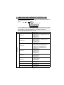
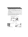
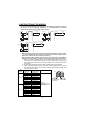
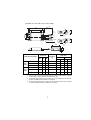
TRANSISTORIZED INVERTER
INSTRUCTION MANUAL
HIGH-DUTY BRAKE RESISTOR
FR-ABR-(H)0.4K to 22K
H
Thank you for choosing the Mitsubishi transistorized inverter option
unit.
This instruction manual gives handling information and precautions for
use of this equipment.
Incorrect handling might cause an unexpected fault. Before using the
equipment, please read this manual carefully to use the equipment to
its optimum.
Please forward this instruction manual to the end user.
Safety Instructions
Do not attempt to install, operate, maintain or inspect this product
until you have read through this instruction manual and appended
documents carefully and can use the equipment correctly.
Do not use this product until you have a full knowledge of the
equipment, safety information and instructions.
In this manual, the safety instruction levels are classified into
"WARNING" and "CAUTION".
WARNING
Denotes that incorrect handling may cause
hazardous conditions, resulting in death or
severe injury.
CAUTION
Denotes that incorrect handling may cause
hazardous conditions, resulting in medium or
slight injury, or may cause physical damage only.
Note that even the
CAUTION level may lead to a serious
consequence under some circumstances. Please follow the
instructions of both levels as they are important to personnel safety.
SAFETY INSTRUCTIONS
1. Electric Shock Prevention
WARNING
•
•
Before starting wiring or inspection, switch power off, wait for
more than 10 minutes, and check for no residual voltage with a
meter etc.
Any person who is involved in the wiring or inspection of this
equipment should be fully competent to do the work.
A-1
2. Fire Prevention
CAUTION
•
•
Mount the brake resistor on a non-combustible surface. Installing
it directly on or near a combustible surface could cause a fire.
Use the alarm signal to switch power off. A failure to do so can
overheat the brake resistor due to a brake transistor failure etc.,
causing a fire.
3. Injury Prevention
CAUTION
•
•
Ensure that the cables are connected to the correct terminals.
Otherwise, damage, etc. may occur.
While power is on or for some time after power-off, do not touch
the brake resistor as it is hot. Touching it can cause burns.
4. Additional Instructions
Also note the following points to prevent an accidental failure, injury,
electric shock, etc.:
(1) Transportation and installation
CAUTION
•
•
Transport products in a correct manner according to their weights.
Not doing so can cause injury.
Install the product in a place secure enough to withstand its weight
according to the instruction manual.
(2) Usage
WARNING
•
•
Do not modify the equipment.
Do not perform parts removal which is not instructed in this
manual. Doing so may lead to fault or damage of the inverter.
(3) Disposal
CAUTION
•
Dispose of this product as general industrial waste.
(4) General instructions
Many of the diagrams and drawings in this instruction manual show
the inverter without a cover, or partially open. Never run the inverter
like this. Always replace the cover and follow the instruction manual
when operating the inverter.
A-2
INSTALLATION INSTRUCTIONS FOR COMPLIANCE WITH UL
Install the high-duty brake resistor FR-ABR as follows:
•
•
•
•
The brake resistor may be mounted horizontally or vertically, depending
on a suitable surface location.
When the brake resistor is mounted externally to the enclosure housing
the inverter, install a solid Type 1 enclosure at least 8 times the volume
size of the brake resistor that incorporates mesh or perforated steel type
ventilation openings at each end of the resistor. Note, the vent openings
shall not be greater than 10 mm diameter.
Secure the enclosure to a non-combustible surface only, such as metal or
concrete.
Mount the brake resistor inside the Type 1 enclosure and wire it in
accordance with the NEC for North America installations or any other
local codes.
Note, when the brake resistor and inverter are mounted together within a
suitable enclosure, the mesh covering is not required. Take care that the
temperature inside the enclosure does not exceed 50°C.
Since the enclosure surface becomes a high temperature, its presents a
possible burn hazard. After installation, the following marking in minimum 3
mm (1/8 in.) sized lettering shall be provided on the enclosure where visible:
CAUTION : HOT SURFACE. TO REDUCE RISK OF BURN - DO NOT TOUCH.
A-3
1. UNPACKING AND CHECKING THE MODEL AND
APPLICABLE INVERTERS
Take the brake resistor out of the package and confirm that the product is
as you ordered and intact.
Type
FR - ABR -
0.4
K
Indicate capacity (kW)
Symbol Voltage class
200V class
No
H
400V class
(For the FR-ABR-H15K, a terminal block for connecting resistors is enclosed
as two resistors need to be connected in parallel.) FR-ABR-15K is indicated
on the resistor. (A type name indicated on the package is different.)
The FR-ABR Series brake resistors are a UL Listed accessory for use only
with the following UL listed inverter models:
200V Class
High-Duty Brake Resistor Model
Applicable Inverter Models
FR-ABR-0.4K
FR-A520-0.4K(-**)
FR-E520-0.4K(C)(-**), FR-E520S-0.4K(-**), FRE510W-0.4K(-**)
FR-A024-0.4K(-**)
FR-S520E-0.4K(-**)
FR-A720-0.4K(-**)
FR-ABR-0.75K
FR-A520-0.75K(-**)
FR-E520-0.75K(C)(-**), FR-E520S-0.75K(-**),
FR-E510W-0.75K(-**)
FR-A024-0.75K(-**)
FR-S520E-0.75K(-**)
FR-A720-0.75K(-**)
FR-ABR-2.2K
FR-A520-1.5K(-**), FR-A520-2.2K(-**)
FR-E520-1.5K(C)(-**), FR-E520-2.2K(C)(-**)
FR-V520-1.5K(-**), FR-V520-2.2K(-**)
FR-A024-1.5K(-**), FR-A024-2.2K(-**)
FR-S520E-1.5K(-**), FR-S520E-2.2K(-**)
FR-A720-1.5K(-**), FR-A720-2.2K(-**)
FR-ABR-3.7K
FR-A520-3.7K(-**)
FR-E520-3.7K(C)(-**)
FR-V520-3.7K(-**)
FR-A024-3.7K(-**)
FR-S520E-3.7K(-**)
FR-A720-3.7K(-**)
FR-ABR-5.5K
FR-A520-5.5K(-**)
FR-E520-5.5K(C)(-**)
FR-V520-5.5K(-**)
FR-A720-5.5K(-**)
FR-ABR-7.5K
FR-A520-7.5K(-**)
FR-E520-7.5K(C)(-**)
FR-V520-7.5K(-**)
FR-A720-7.5K(-**)
FR-ABR-11K
FR-V520-11K(-**)
FR-A720-11K(-**)
FR-ABR-15K
FR-V520-15K(-**)
FR-A720-15K(-**)
FR-ABR-22K
FR-A720-18.5K(-**)
FR-A720-22K(-**)
Note : ** indicates alpha numeric combination which means an inverter type such as A1 and A2.
1
400V Class
High-Duty Brake Resistor Model
Applicable Inverter Models
FR-ABR-H0.4K
FR-A540-0.4K(-**)
FR-E540-0.4K(C)(-**)
FR-A044-0.4K(-**)
FR-A740-0.4K(-**)
FR-ABR-H0.75K
FR-A540-0.75K(-**)
FR-E540-0.75K(C)(-**)
FR-A044-0.75K(-**)
FR-A740-0.75K(-**)
FR-ABR-H1.5K
FR-A540-1.5K(-**)
FR-E540-1.5K(C)(-**)
FR-V540-1.5K(-**)
FR-A044-1.5K(-**)
FR-A740-1.5K(-**)
FR-ABR-H2.2K
FR-A540-2.2K(-**)
FR-E540-2.2K(C)(-**)
FR-V540-2.2K(-**)
FR-A044-2.2K(-**)
FR-A740-2.2K(-**)
FR-ABR-H3.7K
FR-A540-3.7K(-**)
FR-E540-3.7K(C)(-**)
FR-V540-3.7K(-**)
FR-A044-3.7K(-**)
FR-A740-3.7K(-**)
FR-ABR-H5.5K
FR-A540-5.5K(-**)
FR-E540-5.5K(C)(-**)
FR-V540-5.5K(-**)
FR-A740-5.5K(-**)
FR-ABR-H7.5K
FR-A540-7.5K(-**)
FR-E540-7.5K(C)(-**)
FR-V540-7.5K(-**)
FR-A740-7.5K(-**)
FR-ABR-H11K
FR-V540-11K(-**)
FR-A740-11K(-**)
FR-ABR-H15K
FR-V540-15K(-**)
FR-A740-15K(-**)
FR-ABR-H22K
FR-A740-18.5K(-**)
FR-A740-22K(-**)
Note : ** indicates alpha numeric combination which means an inverter type such
as A1 and A2.
2
2. GENERAL INSTRUCTIONS FOR INSTALLATION
(For compliance with UL standard, refer to page A-3.)
• Never mount the resistor near wood, paper or any other combustible
material. Doing so can cause a fire.
• To prevent burns, do not install the resistor in a place where it is readily
accessible. If it is easily accessible, mount in a well-ventilated
enclosure (e.g. punched metal), suitable for the environment.
• Mount the resistor carefully so that the leads do not come from the top
of the resistor.
• Avoid contact with the resistor when running the leads of the resistor
and any other wiring.
Install the resistor in a place with good heat dissipation. The reason for
this is that the surface temperature of the resistor may exceed 360°C in
an operation pattern where the resistor is used frequently.
To increase the heat dissipation effect, we recommend you to install the
resistor on a metal surface outside the enclosure.
Provide an enclosure with good
Use a cooling fan
heat dissipation to prevent
if required.
hazards such as burns.
High-duty brake resistor
How to Install the Resistor
High-duty brake resistor
No contact with
the resistor
Other wiring
Leave at least 3cm
Interval between resistors Installed
Orientation of installed resistor
3
3. INSTRUCTIONS FOR WIRING
When the regenerative brake transistor is damaged, the wiring sequence
as shown in the following diagrams is recommended to prevent
overheating and burnout of the brake resistor.
<Example 1>
Inverter
MC
R
Power
Supply
P
S
PX
T
PR
T(*2)
High-duty brake resistor
(FR-ABR)
R
<Example 2>
ON
ON
MC
C
S
PX
T
PR
Thermal relay High-duty brake resistor
(FR-ABR)
(OCR)(*3)
R
Disconnect jumper. (*1)
MC
OCR
Contact
OFF MC
MC
<Example 3>
Inverter
MC
Power
Supply
R
P
S
PX
T
PR
T(*2)
ON
MC
Thermal relay High-duty brake resistor
(OCR)(*3)
(FR-ABR)
R
Disconnect jumper. (*1)
F
OFF
P
F
B
OFF
Inverter
R
T(*2)
Disconnect jumper. (*1)
F
MC
Power
Supply
OCR
Contact
B
C
MC
• Remove the jumper from across the PR-PX terminals of the inverter.
(*1) This disables (switches off) the built-in brake resistor. (Refer to the
instruction manual of the inverter for details.)
Note that the built-in brake resistor need not be removed. The leads of
the built-in brake resistor need not be disconnected from the terminals.
*1 When you use the FR-E500 series, the FR-V500 series-7.5K or more, 11K or
more and the FR-A700 series inverter, you need not remove the jumper since
that inverter does not have the PX terminals. (Refer to the instruction manual of
the inverter.)
*2 For the 400V class power supply, install a voltage-reducing transformer.
*3 Refer to the table below for the type number of each capacity of thermal relay
and the diagram below for the connection. (Always install a thermal relay when
using the 11K, 15K, 22K.)
Power
Supply
Voltage
200V
400V
High-duty
Brake Resistor
FR-ABR-0.4K
FR-ABR-0.75K
FR-ABR-2.2K
FR-ABR-3.7K
FR-ABR-5.5K
FR-ABR-7.5K
FR-ABR-11K
FR-ABR-15K
FR-ABR-22K
FR-ABR-H0.4K
FR-ABR-H0.75K
FR-ABR-H2.2K
FR-ABR-H3.7K
FR-ABR-H5.5K
FR-ABR-H7.5K
FR-ABR-H11K
FR-ABR-H15K
FR-ABR-H22K
Thermal Relay Type
(Mitsubishi product)
TH-N20CXHZ-0.7A
TH-N20CXHZ-1.3A
TH-N20CXHZ-2.1A
TH-N20CXHZ-3.6A
TH-N20CXHZ-5A
TH-N20CXHZ-6.6A
TH-N20CXHZ-11A
TH-N20CXHZ-11A
TH-N60-22A
TH-N20CXHZ-0.24A
TH-N20CXHZ-0.35A
TH-N20CXHZ-0.9A
TH-N20CXHZ-1.3A
TH-N20CXHZ-2.1A
TH-N20CXHZ-2.5A
TH-N20CXHZ-6.6A
TH-N20CXHZ-6.6A
TH-N20-9A
Contact Rating
1/L1
5/L3
TH-N20
2/T1
6/T3
To the inverter To the ABR
P terminal
110VAC 5A,
220VAC 2A(class AC-11)
110VDC 0.5A,
220VDC 0.25A(class DC-11)
4
• Connect the leads of the high-duty brake resistor to the P and PR
terminals of the inverter. When using the FR-ABR-15K, 22K, connect
two high-duty brake resistors (18Ω) in parallel. When using the FRABR-H15K, connect two high-duty brake resistors (18Ω) in series using
a terminal block enclosed.
FR-ABR-H15K brake resistor
To the inverter PR terminal
Terminal block
enclosed
To the inverter P terminal
(To the thermal relay T3 terminal.)
• If you extend the high-duty resistor lead wire to use, use the wire with
a size as noted below and not exceeding 5m in length. Installation shall
be in accordance with the North American or Canadian Electrical Code
and any applicable provincial codes (codes of each state).
CAUTION
1. The high-duty brake resistor cannot be used with a brake
unit, high power factor converter, power return converter,
built-in brake etc.
2. Twist the leads of the high-duty brake resistor when increasing their length 2m or more. (The wire size used should be
minimum 14 AWG (2.1mm2)).
Note that even the twisted leads cannot be made longer than
5m. Doing so can cause an inverter failure.
3. The FR-ABR-(H)11K, 15K, 22K can not be used with the FRA500 series.
4. INSTRUCTIONS FOR USE
• Setting of inverter parameters
The parameter setting method varies with the inverter series. Refer
to the instruction manual of the inverter.
5
5. SPECIFICATIONS
Permissible duty and torque
Item
FR-ABR-
(200V Class)
FR-ABR-H
(400V Class)
0.75
0.4K 0.75
K 2.2K 3.7K 5.5K 7.5K 11K 15K 22K 0.4K K 1.5K 2.2K 3.7K 5.5K 7.5K 11K 15K 22K
Braking 150%
100% 5s
100% 5s
torque
5s
Permissib
10%ED
6%ED
10%ED
6%ED
le duty*
* The permissible duty represents the braking capability including the motor
loss.The actual duty of the resistor is slightly lower than that.
6. OUTLINE DIMENSIONS
FR-ABR-0.4K to 7.5K, H0.4K to H7.5K
500 +200
W
W1 ±1
W2
B1
A1
φd1
A1
5.3
A2
B2
Glass-braided cable
2.0mm2 white
φd2
D
2.5
H
A2
Dimensions (Unit: mm)
Brake Resistor Model
400V Class
200V Class
W
FR-ABR-0.4K
FR-ABR-0.75K
FR-ABR-2.2K*1
FR-ABR-3.7K
FR-ABR-5.5K
FR-ABR-7.5K
FR-ABR-H0.4K
FR-ABR-H0.75K
FR-ABR-H1.5K
FR-ABR-H2.2K
FR-ABR-H3.7K
FR-ABR-H5.5K
FR-ABR-H7.5K
W1
D
H
140 125 100 40
215 200 175 40
240 225 200 50
21
21
26
200
100
60
215
335
400
115
140
215
240
215
335
400
33
33
40
21
21
21
26
33
33
40
40
25
20
1200
700
350
250
150
110
75
200
320
385
100
125
200
225
200
320
385
W2
Resistance
(Ω)
175
295
360
75
100
175
200
175
295
360
61
61
80
40
40
40
50
61
61
80
*1 Used for 1.5K and 2.2K.
6
Crimping Terminal
(Unit: mm)
A1
A2
B 1 d 1 B2 d 2
7.0 4.3 7.0 4.3
9.5 5.3 9.5 5.3
7.0 4.3 7.0 4.3
9.5 5.3 9.5 5.3
FR-ABR-11K, 15K, 22K, H11K, H15K, H22K
700+200
W
W1 ±1
W2
B1
A1
80.5 ±1
5.3
φd1
A1
A2
B2
Glass-braided cable
2.0mm2 white
φd2
A2
2.5
50
100
Dimensions
(Unit: mm)
Brake Resistor Model
Resistance
(Ω)
Crimping Terminal
(Unit: mm)
A1
A2
W
W1
W2
B1
d1
B2
d2
400
385
360
13
12
6.4
9.5
5.3
200V
FR-ABR-15K*1
Class
FR-ABR-22K*3
300
285
260
18
12
8.4
12
8.4
400
385
360
13
12
8.4
12
8.4
FR-ABR-H11K
400V
FR-ABR-H15K*2
Class
FR-ABR-H22K*4
400
385
360
52
12
6.4
9.5
5.3
300
285
260
18
12
8.4
12
8.4
450
435
410
52
9.0
6.4
9.0
6.4
FR-ABR-11K
*1 For the 15K, connect two resistors (18Ω) in parallel.
*2 For the H15K, connect two resistors (18Ω) in series. FR-ABR-15K is indicated
on the resistor. (same resistor as the 200V class 15K)
*3 For the 22K brake resistor, configure so that two 13Ω resistors are connected in
parallel. FR-ABR-22K is indicated on the resistor.
*4 For the H22K brake resistor, configure so that two 52Ω resistors are connected
in parallel. FR-ABR-H22K is indicated on the resistor.
7
7. BRAKING CAPABILITIES
7.1
Continuous Permissible Power
Continuous
Resistance Permissible
Power
FR-ABR-0.4K
FR-ABR-0.75K
FR-ABR-2.2K
FR-ABR-3.7K
FR-ABR-5.5K
FR-ABR-7.5K
FR-ABR-11K
FR-ABR-15K
200Ω
100Ω
60Ω
40Ω
25Ω
20Ω
13Ω
9Ω*1
60W
80W
120W
155W
185W
340W
560W
805W
FR-ABR-22K
6.5Ω*1
1120W
Continuous
Resistance Permissible
Power
Model
400V Class
200V Class
Model
1200Ω
700Ω
350Ω
250Ω
150Ω
110Ω
75Ω
52Ω
FR-ABR-H0.4K
FR-ABR-H0.75K
FR-ABR-H1.5K
FR-ABR-H2.2K
FR-ABR-H3.7K
FR-ABR-H5.5K
FR-ABR-H7.5K
FR-ABR-H11K
45W
75W
115W
120W
155W
185W
340W
530W
870W
36Ω*2
1060W
FR-ABR-H22K
26Ω*3
*2 When two resistors are connected in series.
*3 When two resistors are connected in parallel.
FR-ABR-H15K
*1 When two resistors are connected in series.
7.2 Short-Duration Permissible Power per Braking
• 200V
140
Class
Time(S)
120
100
80
60
2.2K
15K
7.5K 11K
5.5K
22K
3.7K
40
0.75K
20
0.4K
0
10
• 400V
Class
20 30
50
70 100
500 700 1000
200 300
2000 3000 5000 7000 10000 20000
15000
Power(W)
Time(S)
140
120
100
H11K
80
H7.5K
60
H22K
H15K
H3.7K
H1.5K
40
H5.5K
H2.2K
H0.75K
20
H0.4K
0
10
20 30
50 70 100
200 300
500 700 1000
2000 3000 5000700010000 20000
15000
POWER(W)
8
REVISIONS
*The manual number is given on the bottom left of the back cover.
Print Date
*Manual Number
Nov., 1998
Mar., 2001
IB(NA)-66891-A
IB(NA)-66891-B
Revision
First edition
Partial Additions
• Applicable inverters
• Instructions for wiring
Apr., 2002
IB(NA)-66891-C
Additions
FR-ABR-11K, FR-ABR-15K
Aug., 2002
IB(NA)-66891-D
Additions
FR-ABR-H11K, FR-ABR-H15K
Partial Addition
Instructions for wiring
Oct., 2003
IB(NA)-66891-E
Additions
UL compliance
Mar., 2004
IB(NA)-66891-F
Modifications
Outline dimentions, outline dimention
drawings
Aug., 2005
IB(NA)-66891-G
Additions
FR-ABR-22K
Nov., 2005
IB(NA)-66891-H
Additions
• FR-ABR-H22K
• FR-A740 specifications