1
AD2088
Keyboard Operator’s Manual
© Copyright 2000 Sensormatic Video Systems Division
All rights reserved
AD2088
Keyboard Operator’s Manual
Copyright 2000
All rights reserved.
No part of this manual may be reproduced in any form
without written permission from Sensormatic® Electronics Corporation.
8000-1811-01, Revision A
WARNING
Do not install this product in hazardous areas where highly combustible or explosive
products are stored or used.
To reduce the risk of fire or electric shock, do not expose appliance to rain or moisture.
EQUIPMENT MODIFICATION CAUTION
Equipment changes or modifications not expressly approved by Sensormatic Electronics Corporation, the party
responsible for FCC compliance, could void the user's authority to operate the equipment and could create a
hazardous condition.
FCC COMPLIANCE
This equipment has been tested and complies with the limits for a Class A digital device, according to Part 15 of the
FCC Rules. These limits provide reasonable protection against harmful interference when the equipment operates in
a commercial environment. This equipment generates, uses, and can radiate radio frequency energy, and, if not
installed and used according to these instructions, may cause harmful interference to radio communications.
Operation of this equipment in a residential area is likely to cause harmful interference. If this equipment is used in a
residential area, users must correct the interference at their own expense.
WARRANTY DISCLAIMER
Sensormatic Electronics Corporation makes no representation or warranty of the contents of this manual and
disclaims any implied warranties of merchantability or fitness. Sensormatic Electronics Corporation reserves the
right to revise this manual and change its content without obligation to notify any person of these revisions.
SOFTWARE LICENSE AGREEMENT
A Software License Agreement appears in Appendix D of this manual. Please read it carefully. Using the AD2088
system software indicates that you accept the terms and conditions of this agreement.
No part of this manual may be reproduced in any form without written permission from Sensormatic® Electronics
Corporation.
© Copyright 2000 Sensormatic Video Systems Division
All rights reserved
Trademarked names are used throughout this manual. Rather than place a symbol at each occurrence, trademarked
names are designated with initial capitalization. Inclusion or exclusion is not a judgment on the validity or legal
status of the term.
PN- 8000-1811-01, Revision A
Table of Contents
CHAPTER 1: ABOUT THE AD2088 KEYBOARD CONTROLLER................................................................ 1-1
AD2088 FEATURES ................................................................................................................................................ 1-1
AD2088 KEYBOARD OVERVIEW ............................................................................................................................ 1-2
CHAPTER 2: CONNECTION AND SETUP OF THE AD2088.......................................................................... 2-1
SUPPLIED EQUIPMENT ............................................................................................................................................. 2-1
Connecting to a Switching System ..................................................................................................................... 2-1
Connections for Cable Distance of Seven Feet or Less.....................................................................................................2-1
Connections for Cable Distance of Greater than Seven Feet.............................................................................................2-2
Power Connections ...........................................................................................................................................................2-2
Installation Precautions.....................................................................................................................................................2-2
KEYBOARD SETUP .................................................................................................................................................. 2-3
Setting Keyboard Parameters ............................................................................................................................ 2-3
To Enter Setup Mode ........................................................................................................................................................2-3
To Change the Baud Rate .................................................................................................................................................2-3
To Set the Brightness Level ..............................................................................................................................................2-3
To Set the Speaker Volume...............................................................................................................................................2-4
To Set the Pan / Tilt / Zoom Motion Control Option........................................................................................................2-4
Resetting Keyboard Parameters ........................................................................................................................................2-4
BUILT-IN KEYBOARD OPERATIONS TEST ................................................................................................................ 2-5
Procedure to Initiate Built-In Test ....................................................................................................................................2-5
Speaker Test......................................................................................................................................................................2-6
LED Lamp Test.................................................................................................................................................................2-6
LED Brightness Test .........................................................................................................................................................2-6
Seven Segment LED Test .................................................................................................................................................2-6
Joystick Calibration / Speed Test ......................................................................................................................................2-6
Key Functionality Test......................................................................................................................................................2-8
Keyswitch Test..................................................................................................................................................................2-8
Serial Communications Test .............................................................................................................................................2-8
ROM Checksum Test........................................................................................................................................................2-9
CHAPTER 3: USING THE AD2088 IN OPERATE MODE ............................................................................... 3-1
User Numbers and Passcodes............................................................................................................................ 3-1
Logging On to the System.................................................................................................................................................3-1
Logging Off from the System............................................................................................................................................3-1
Selection of Monitor or VCR Mode of Operation .............................................................................................. 3-1
MONITOR MODE OPERATIONS (KEYSWITCH IN “OPERATE” POSITION) .................................................................... 3-2
Selecting Monitors ............................................................................................................................................. 3-2
Calling a Camera to View on a Monitor............................................................................................................ 3-2
Controlling a Camera's Pan and Tilt................................................................................................................. 3-2
Locking and Unlocking a Camera ..................................................................................................................... 3-3
Controlling Camera Zoom ................................................................................................................................. 3-3
Controlling Camera Focus ................................................................................................................................ 3-3
Controlling the Camera Iris............................................................................................................................... 3-3
Controlling Camera Flip ................................................................................................................................... 3-3
Auto Focus / Auto Iris ........................................................................................................................................ 3-3
Calling Presets (Shots)....................................................................................................................................... 3-4
Running System Tours........................................................................................................................................ 3-4
Holding a Tour................................................................................................................................................... 3-4
Re-Starting a Tour on Hold ............................................................................................................................... 3-4
Calling Salvos .................................................................................................................................................... 3-5
Auxiliary Control ............................................................................................................................................... 3-5
Acknowledging Alarms ...................................................................................................................................... 3-5
Viewing Satellite Sites........................................................................................................................................ 3-5
Running Patterns ............................................................................................................................................... 3-6
Table of Contents
iii
Running a Macro ............................................................................................................................................... 3-6
VCR MODE OPERATIONS (KEYSWITCH IN OPERATE POSITION) ............................................................................... 3-7
Selecting VCRs................................................................................................................................................... 3-7
CHAPTER 4: PROGRAMMING WITH THE AD2088 ...................................................................................... 4-1
USING THE AD2088 IN PROGRAM MODE ................................................................................................................ 4-1
Setting Presets.................................................................................................................................................... 4-1
Setting Scratch Pad Tours.................................................................................................................................. 4-1
Programming Patterns....................................................................................................................................... 4-1
Defining Patterns (for use with AD168 and CCM only) .................................................................................... 4-2
Clearing Patterns (for use with AD168 and CCM only).................................................................................... 4-2
Arming a Monitor .............................................................................................................................................. 4-2
Disarming a Monitor ......................................................................................................................................... 4-2
Programming Macros ........................................................................................................................................ 4-3
Macro Examples ...............................................................................................................................................................4-3
Advanced Macro Examples ..............................................................................................................................................4-3
Synchronization of Macro Programming........................................................................................................... 4-4
Keyboard to CPU Transfer................................................................................................................................................4-4
CPU to Keyboard Transfer................................................................................................................................................4-5
Deleting Macros................................................................................................................................................. 4-5
USING THE AD2088 IN MENU MODE ...................................................................................................................... 4-6
APPENDIX A: SPECIFICATIONS ...................................................................................................................... A-1
APPENDIX B: TROUBLESHOOTING ............................................................................................................... B-1
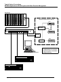
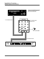
APPENDIX C: TYPICAL SYSTEM CONNECTIONS ...................................................................................... C-1
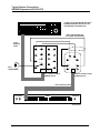
AD2088 KEYBOARDS TO AD1024 SYSTEM WITH VIDEO RECORDER MGT ............................................................C-1
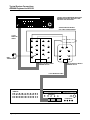
AD2088 TO AD1024 CPU (SEVEN FEET OR LESS)..................................................................................................C-2
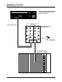
AD2088 TO AD1024 CPU (GREATER THAN SEVEN FEET) ......................................................................................C-3
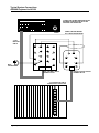
AD2088 TO AD2150 (SEVEN FEET OR LESS) ..........................................................................................................C-4
AD2088 TO AD2150 (GREATER THAN SEVEN FEET) ...............................................................................................C-5
AD2088 TO AD168 (SEVEN FEET OR LESS) ............................................................................................................C-6
AD2088 TO AD168 (GREATER THAN SEVEN FEET) .................................................................................................C-7
AD2088 TO MEGAPOWER 48 (FOR LESS & GREATER THAN 7 FEET) .......................................................................C-8
BUILT-IN TEST CONNECTION ..................................................................................................................................C-9
APPENDIX D: SOFTWARE LICENSE AGREEMENT.................................................................................... D-1
APPENDIX E: MONITOR ARMING COMMANDS......................................................................................... E-1
GLOSSARY............................................................................................................................................................. G-1
MACRO KEY LABELS......................................................................................................................................... L-1
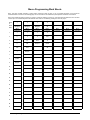
MACRO PROGRAMMING WORK SHEETS .................................................................................................. M-1
INDEX........................................................................................................................................................................I-1
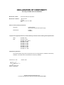
DECLARATION OF CONFORMITY .......................................................................................................................
iv
AD2088 Operator’s Manual
Chapter 1: About the AD2088 Keyboard Controller
This chapter describes the features of the AD2088 keyboard. It also describes the location and
function of the keyboard's front panel components.
AD2088 Features
The AD2088 is a video control station that is fully compatible with the Sensormatic MegaPower
48, AD168, and AD1024 matrix switcher/controller systems. The AD2088 enables the user to
view and control cameras and video recorders at local and remote facilities, and to control
auxiliary devices such as door locks and lights. Additionally, the operator can acknowledge alarms
with the unit. The aforementioned functions are accomplished in the keyboard’s Operate Mode.
Operators with key privileges can also perform programming functions with the AD2088. These
functions include programming of presets (targets), patterns, scratch-pad tours, and macros.
Macros are user programmed functions made up of as many as 21 keystrokes that are executed
with a single keystroke. Operators can also arm and disarm monitors for display of system alarms.
These functions are accomplished in the Program Mode.
Menu programming enables operators to set up the parameters of American Dynamics switching
systems. System setup is accomplished in the Menu Mode.
A summary listing of AD2088 features follows:
•
site ID - selects a site for satellite switching
•
monitor/camera selection - provides selection for viewing and control
•
pan/tilt and lens control - pan, tilt, and zoom control through joystick positioning. Focus and
iris adjustments through lens control keys
•
video recorder control and operation – enables selection of video recorders and execution of
the following functions: Play, Stop, Fast-Forward, Rewind, Record, Pause, and Eject
•
macro key programming and operation – up to 1000 macros divided among eight macro keys
enable multi-step operation with a single keystroke
•
joystick “Flip” push-button - enables user to flip cameras 180º from established position
•
tour functions - enables programming, running, and control of camera sequences
•
salvo functions - enables programming and simultaneous callup of multiple camera scenes
•
alarm functions - supports monitor alarm arming, disarming, and alarm acknowledgment
•
pattern and preset functions - enables programming and display of patterns and presets (shots)
•
selectable baud rate - 1200, 2400, 4800, 9600, 19,200, 38,400 bps (1200 default)
•
selectable LED brightness - enables eight different brightness levels
•
selectable speaker volume - enables eight different volume levels
•
auto focus/auto iris capability - supported when used with DeltaDome units
About the AD2088 Keyboard Controller
1-1
10
A
C
7
B
D
12
14
13
20
21
8
.
SITE
CAMERA
MONITOR
ON
OFF
4
VCR
Sk
3
F1
F2
PROG
SITE
RUN
1
HOLD
SALVO
OPERATE
2
4
5
6
POKER
PIT
COUNT
ROOM
1
2
3
4
5
6
7
8
9
MON
0
CAM
Mk
E
Ck
CLOSE
PATRN
15
OPEN
FOCUS
NEAR
FAR
TASK
8
7
PRE
SSET
HOT
IRIS
3
SLOTS CRAPS BLACK
JACK
CONTROL
AUXILIARY
ENTER
2
PROGRAM
MENU
1
LAST
NEXT
5
6
CLEAR
11
9
VCR
ACK
18
19
16
17
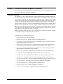
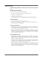
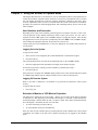
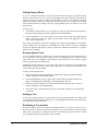
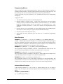
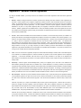
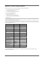
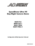
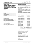
AD2088 Keyboard Overview
The AD2088 keyboard is comprised of the following elements:
A.
Site Display - shows the number of the site entered with the
keypad when the SITE key (Sk) is pressed.
10.
RUN key - runs system and scratch pad tours.
B.
Monitor / VCR Display - shows the number of the monitor
or VCR entered with the keypad when the MON (Mk) or
VCR key is pressed.
11.
MACRO keys – Each of the eight macro keys calls a
specified macro whose number is entered on the numeric
keypad.
C.
Camera Display - shows the number of the camera entered
with the keypad when the CAM key (Ck) is pressed.
D.
Enter Display - shows the number entered on the
NUMERIC KEYPAD (E).
12.
OFF/Page Left key/ Stop - turns off auxiliary device in
Monitor Operate mode. Displays page to left in Menu mode.
Stops VCR in VCR Operate mode.
E.
Numeric Keypad – keys ranging from 0 to 9 that enable the
user to select specific cameras, monitors, salvos, tours,
presets, patterns, auxiliaries, recorders, sites, and macros.
13.
ON/Page Right key/ Record - turns on auxiliary device in
Monitor Operate mode. Displays page to right in Menu mode.
Starts VCR recording in VCR Operate mode.
1.
Keyswitch - enables the user to switch to the Operate,
Program, or Menu modes of operation. When the keyswitch
is set to Menu position, the page and cursor navigation
functions of the multi-function keys are activated.
14.
CLOSE/Page Up key/ Pause - closes camera iris in Operate
mode. Displays prior page up in Menu mode. Pauses VCR in
VCR Operate mode.
2.
Joystick - enables the user to pan, tilt, zoom and flip the
camera under keyboard control.
15.
OPEN/Page Down key/ Play - Opens camera iris in Monitor
Operate mode. Displays next menu page down in Menu
mode. Plays VCR in VCR Operate mode.
3.
PROG key - enables the user to set scratch-pad tours and
patterns, as well as a number of other switching system
functions.
16.
NEAR/Left Arrow key/ Rewind - Adjusts focus of near
objects in Monitor Operate mode. Moves cursor left one
character in Menu mode. Rewinds VCR in VCR Operate
mode.
4.
F1 & F2 keys - special functions keys used to implement
basic system commands and DeltaDome control F1 & F2
keys - special functions keys used to implement basic
system commands and DeltaDome control
17.
FAR/Right Arrow / Fast Forward key - Adjusts focus of
distant objects in Monitor Operate mode. Moves cursor right
one character in Menu mode. Fast Forwards VCR in VCR
Operate mode.
5.
LAST key - calls the prior camera displayed in a sequence
(tour).
18.
VCR/Up Arrow key – Enables selection of VCR mode of
operation
6.
NEXT key - calls the next camera displayed in a sequence
(tour).
19.
ACK key /Down Arrow /Eject Key- Acknowledges alarms,
runs tours, sets and repeats patterns. Ejects tape in VCR
Operate mode
7.
HOLD key - Holds the current camera in a sequence (tour).
20.
PRESET/Enter key - Calls presets in Operate mode. Sets
presets in Program mode. Stores entered menu data.
8.
SALVO key - calls a specified salvo whose number is
entered on the numeric keypad.
21.
PATRN/Exit key - runs and repeats patterns in Operate
mode. Sets patterns in Program mode. Exits Menu mode.
9.
CLEAR key - clears data entered on the numeric keypad
1-2
MULTI-FUNCTION KEYS
AD2088 Operator's Manual
Chapter 2: Connection and Setup of the AD2088
This chapter describes the power and data connections between the AD2088 keyboard and the
switching system being used. It also describes the setup of communications protocols and other
keyboard parameters. Additionally, it describes built-in test procedures used to verify the
operational integrity of the keyboard.
Supplied Equipment
The AD2088 is supplied with the following equipment and accessories:
•
•
•
•
•
•
•
Wall Transformer (specified for national and local electrical requirements)
One dual eight pin, wall-mount terminal block, with three jumper wires
One single eight pin, wall-mount terminal block
Two seven foot, eight conductor modular cables
Eight clear key caps and four white key caps for the AD2088 macro key section
Pre-printed macro key labels
One extractor tool for macro key removal
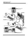
The transformer is connected from the wall to the terminal block. Power is then routed through the
dual terminal block to the keyboard's eight pin RJ-45 port via the seven foot cable.
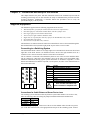
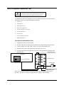
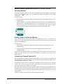
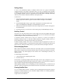
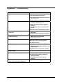
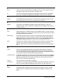
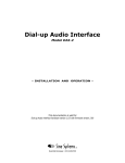
Connecting to a Switching System
The dual terminal block consists of two single eight-screw terminal blocks located on the left and
right sides of the block interior (see illustration below). Each of the eight terminal screws in a
connector set are routed to an RJ-45 connector at the bottom of the block.
The J1 connector is connected to the AD2088 keyboard via one of the seven foot modular cables.
The J2 connector is connected to the switching system via the other seven foot modular cable.
Additional information showing typical system connections is included in Appendix C of this
manual. Pin definitions for both the keyboard (J1) and system (J2) sides of the terminal block are
listed in the table below
4
5
5
3
4
6
6
3
7
2
7
8
1
8
2
1
Keyboard
J1
System
J2
Dual Terminal Block
Screw
Function
1
Transformer Power In (J1 only)
2
Shield
3
Not Used
4
RS-232 RCD
5
RS-232 XMIT,
6
Not Used
7
Ground
8
Transformer Power In (J1 only)
!
Power and Data Connections Only
Not for Connection to Telephone Lines
Dual Terminal Block Screw Designations
Connections for Cable Distance of Seven Feet or Less
For switching system connections where keyboard-to-system cable distance is seven feet or less,
make the following connections using the jumpers included with the dual terminal block
J1 Pins
J2 Pins
4 (rcd) ➜
5 (xmit)
5 (xmit) ➜
7 (ground) ➜
4 (rcd)
7 (ground)
After connecting the jumpers, connect one of the seven foot modular cables from the J2 (system)
jack of the dual terminal block, to the appropriate RS-232 port on the switching system. Connect
Connection and Setup of the AD2088
2-1
the other seven foot modular cable from the J1(keyboard) jack of the dual terminal block, to the
RJ-45 jack of the keyboard. :
Connections for Cable Distance of Greater than Seven Feet
For switching system connections where keyboard-to-system cable distance is greater than seven
feet, the following components are required
•
Dual terminal block supplied with the AD2088
•
A three-wire, shielded, 18 AWG cable supplied by the installer
•
Single terminal block supplied with the AD2088
Use the three-wire cable to connect the keyboard and switching system terminal blocks. The
following table provides the connection points
Dual Block (J1 side) screws
Single Block screws
4 (rcd)➜
5 (xmit)
5 (xmit)➜
4 (rcd)
7 (ground)➜
7 (ground)
Note: the cable shield connects to Pin 2 of the
single terminal block
After connecting the three-wire cable to the respective terminal blocks, connect one of the seven
foot modular cables supplied with the AD2088 from the J1(keyboard) jack of the dual terminal
block to the RJ-45 jack of the keyboard. Connect the other seven foot modular cable from the RJ45 jack of the single terminal block to the appropriate RS-232 port on the switching system.
Power Connections
Depending on national and local electrical requirements, the AD2088 is supplied with either a 120
VAC or a 230 VAC transformer. The 230 VAC transformer is supplied with a Euro-style IEC 320
type inlet. An appropriate detachable cord should be connected between the IEC 320 inlet and the
power source.
Connect the output leads from the wall transformer to screws 1 and 8 on the J1(keyboard) side of
the dual terminal block. All power to the AD2088 is supplied from this connection.
!
CAUTION!
DO NOT INSERT THE WALL TRANSFORMER INTO THE POWER
SOURCE UNTIL ALL CONNECTIONS HAVE BEEN VERIFIED
Note: Typical system and test connections are illustrated in Appendix C of this manual.
Installation Precautions
The keyboard unit is susceptible to high electrostatic discharge potentials. Care should be taken to
locate the unit so as to reduce the likelihood of accidental contact with ESD potentials, such as
walking on a carpet under very dry conditions.
Should accidental contact occur, and the keyboard unit experiences loss of camera control,
momentarily remove power to the unit. This will re-establish communication with the connected
unit or system, and reset the camera status.
This installation should be made by qualified service personnel, and should conform to all local
electrical codes. Safeguards must be taken to avoid unintentional operation by employees and
maintenance personnel working about the premises, by falling objects, by customers, by building
vibration, and by similar causes.
2-2
AD2088 Operator's Manual
Keyboard Setup
The AD2088 keyboard communicates via RS-232 protocol. Keyboard setup up the keyboard
involves setting the keyboard's baud rate, LED brightness, speaker volume, and PTZ motion
control.
Setting Keyboard Parameters
The operator can set the following four keyboard parameters:
•
Baud Rate – 1200 (default), 2400, 4800, 9600, 19,200, and 38,400 bps
•
LED Brightness - eight brightness levels
•
Speaker Volume - eight volume levels
•
Pan/Tilt/Zoom Motor Control – two control options can be set automatically or manually
To Enter Setup Mode
1.
Turn the three-position keyswitch to the MENU position.
2.
Press the F1 key. "SETUP BAUD =" appears in the CAMERA display. The current value of
the baud rate appears in the ENTER display.
To Change the Baud Rate
1.
Press the NEXT key to cycle through the available baud rate settings in the forward direction:
1200, 2400, 4800, 9600, 19,200, and 38,400. Press the LAST key to cycle through in the
reverse direction. The factory default setting is 1200 baud.
2.
When the appropriate baud rate appears in the display, press the PROG key to save the
selection. You now have the option to either set the brightness level using the following
procedure, or exit setup mode by pressing the F1 key, turning the keyswitch to OPERATE,
MENU, and then back to OPERATE again.
To Set the Brightness Level
1.
After baud rate selection has been completed, the message "LEDS =" appears in the
CAMERA display. The brightness level (an integer from 1 to 8) appears in the ENTER
display. The integer 1 signifies minimum brightness. The integer 8 signifies maximum
brightness. 8 is the factory default setting.
2.
To change the currently displayed brightness level, cycle through the levels using the NEXT
or LAST keys to move in forward or reverse direction respectively. Each time the level
changes, the intensity of the displayed characters changes as well.
3.
When the appropriate integer appears in the ENTER display, press the PROG key to save the
selection. You now have the option to either set the speaker volume level using the following
procedure, or exit setup mode by pressing the F1 key, turning the keyswitch to OPERATE,
MENU, and then back to OPERATE again.
Connection and Setup of the AD2088
2-3
To Set the Speaker Volume
1.
After LED brightness level selection has been completed, the message "SOUND" appears in
the CAMERA display. The speaker volume level ("Off" or integer values from 1 to 7) appears
in the ENTER display. "Off" indicates the speaker is disabled. The integer 1 signifies the
minimum volume level. The integer 7 signifies the maximum volume level. 7 is the factory
default setting.
2.
To change the currently displayed volume level, cycle through the levels using the NEXT or
LAST keys to move in forward or reverse direction respectively. Each time the level changes,
a short tone sounds indicating the new level.
3.
When the appropriate level appears in the ENTER display, press the PROG key to save the
selection. You now have the option to either set the PTZ motion control option using the
following procedure, or exit the setup mode by pressing the F1 key, turning the keyswitch to
OPERATE, MENU, and then back to OPERATE again.
To Set the Pan / Tilt / Zoom Motion Control Option
Depending on the particular switching system that is used with the AD2088 keyboard, the pan, tilt,
and zoom (PTZ) motions of the system cameras are controlled by one of two methods: Repeat or
Make/Break. Detailed descriptions of these two methods are beyond the scope of this manual, but a
system administrator will be advised of the appropriate method to use, and will make the
appropriate setting accordingly.
1.
After speaker volume level selection has been completed, the letters "rpt =" appear in the
CAMERA display. "AUTO" will appear in the ENTER display. “AUTO” indicates that the
switching system being used will automatically select either the Repeat or Make/Break control
method.
2.
You can step through the “AUTO”, "OFF" and "ON" states by using the NEXT or LAST
keys. If "OFF" is displayed, the Repeat method will be set off . If "ON" is displayed the
Repeat method will be set on. The AD168 system operates with Repeat set to OFF. American
Dynamics systems that operate with Repeat set to ON include AD1650B, AD1024, AD2052,
AD2150, and AD2350. Consult with your system administrator about the appropriate setting
for your system.
3.
When the appropriate state appears in the ENTER display, press the PROG key to save the
selection. You now have the option to either set the baud rate using the procedure indicated on
page 2-3, or exit the setup mode by pressing the F1 key, turning the keyswitch to OPERATE,
MENU, and then back to OPERATE again.
Resetting Keyboard Parameters
2-4
1.
To reset baud rate, LED brightness level, speaker volume level, and the PTZ motion control
option to factory default settings, first unplug the keyboard's wall transformer.
2.
Press and hold the F1 and PROG keys simultaneously while plugging the transformer back in.
AD2088 Operator's Manual
Built-in Keyboard Operations Test
!
CAUTION !
The following procedures expose internal electrical components
and should be performed by qualified service personnel only.
The AD2088 has built-in test capability to verify the operational integrity of the unit's hardware
and firmware. Built-in test functions include the following:
•
speaker test
•
LED lamp test
•
LED brightness test
•
LED seven segment test
•
joystick calibration / speed test
•
key functionality test
•
keyswitch test
•
serial communications test
•
ROM checksum test
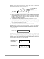
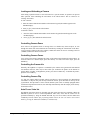
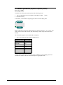
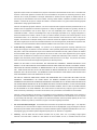
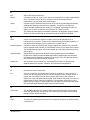
Procedure to Initiate Built-In Test
1.
Unplug the keyboard's wall transformer.
2.
Disconnect the matrix switching system's modular cable from the dual terminal block (J2).
3.
Connect a jumper wire to pins 4 and 5 on the J1 side of the dual terminal block.
4.
Detach the bottom plate of the keyboard by removing the four screws.
5.
Press and hold down the button labeled "test switch", while simultaneously plugging in the
wall transformer.
XMIT/RCD SELF-TEST
JUMPER CONNECTION
AD2088 KEYBOARD
UNDERSIDE
5
4
5
3
TEST SWITCH
4
6
6
7
MODULAR CABLE
DUAL TERMINAL BLOCK
3
2
7
1
8
8
2
TRANSFORMER
1
J1
J2
DO NOT CONNECT TO SYSTEM
DURING BUILT-IN TEST
Each test is performed in sequence. Press the test switch button to advance to the next test
procedure. To quit the test sequence, unplug and then re-plug the wall transformer.
Connection and Setup of the AD2088
2-5
Speaker Test
The speaker test performs an audible check of the keyboard's speaker. A series of audio tones step
through the frequency range of the speaker. During this test the CAMERA display shows the
message "SOUND". The speaker test is repeated automatically, until the test switch button is
pressed to advance to the LED lamp test.
LED Lamp Test
The LED lamp test simultaneously illuminates all segments of all LEDs in the four keyboard
display sections. Press the test switch button to advance to the LED brightness test.
LED Brightness Test
In this test, all LEDs are stepped through the eight levels of intensity. The eight step sequence
repeats continuously until the test switch button is pressed to advance to the seven segment LED
test.
Seven Segment LED Test
This test simultaneously illuminates one of the seven segments for all 18 of the display LEDs for a
brief interval. The next segment then illuminates, and then the next, and so on. The seven segment
illumination cycle repeats continuously until the test switch button is pressed to advance to the
joystick calibration / speed test.
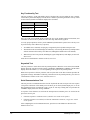
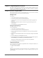
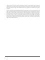
Joystick Calibration / Speed Test
This test checks the joystick’s calibration, speed, and position. Codes representing these
parameters appear in the keyboard’s ENTER, CAMERA, and MONITOR/VCR displays.
When the joystick is in the center or “hands-free” position, dash marks appear in the ENTER
display. The number “128” appears once in the MONITOR/VCR display, and twice in the
CAMERA display.
SITE
MONITOR
1 2 8
CAMERA
1 2 8 1 2 8
ENTER
The dashes in the ENTER display indicate that no pan or tilt commands are being transmitted.
“128” in the MONITOR/VCR display indicates that the joystick is not being twisted in a clockwise
or counter-clockwise direction. Twisting clockwise zooms in. Twisting counter-clockwise zooms
out.
The left-most “128” in the CAMERA display indicates the hands-free position for panning. The
right-most “128” indicates the hands-free position for tilting. Note: due to variations in
components and voltage sources, the center and endpoint numeric values for each keyboard may
vary by small amounts.
If the dashes are not displayed when the joystick is physically centered (when the operator
releases the joystick), then the joystick is not properly calibrated. Contact American Dynamics
Technical Support Center at 1-800-442-2225.
2-6
AD2088 Operator's Manual
When the joystick is moved in any direction away from the center position, the dashes in the
ENTER display are replaced by a four-digit movement code:
pan speed (1-8)
pan direction (left or right)
tilt speed (1-8)
tilt direction (up or down)
Enter Display
(Joystick in Motion)
8
L
1
d
•
From left to right, the first digit represents the pan speed. Speed is directly proportional to the
distance from the joystick’s center position. “1” represents the slowest pan speed, and is
therefore the position closest to the center. “8” represents the fastest pan speed, and is
therefore the position furthest from the center.
•
The second digit (left to right) represents the panning direction (left or right, "L" or "r").
•
The third digit (left to right) shows the tilt speed (up or down, "U" or "d"). Speed is directly
proportional to the distance from the joystick’s center position. “1” represents the slowest tilt
speed, and is therefore the position closest to the center. “8” represents the fastest tilt speed,
and is therefore the position furthest from the center.
•
The fourth digit (left to right) shows the tilt direction (up or down, “U” or “d”)
When the joystick is moved left or right, or forwards or backwards, the numbers on the CAMERA
display change. Moving the joystick to the left or forwards increases the numeric values. Moving
to the right or backwards decreases the numeric values. Zero is the lower limit for numeric values.
“255” is the upper limit.
CAMERA display:
1
2
8
1
2
8
When the joystick is twisted clockwise or counter-clockwise, the numbers on the MONITOR/VCR
display change. Twisting clockwise performs the zoom-in or telephoto function. When twisting
clockwise, an “I” (for zoom in) should appear before the digits, and the digits will increase.
Twisting counter-clockwise performs the zoom-out or wide function. When twisting counterclockwise, a “O”(for zoom out) should appear before the digits, and the digits will decrease. Zero
is the lower limit for numeric values. “255” is the upper limit.
MONITOR/VCR display:
Clockwise Motion
I
2
0
2
O
1
0
2
MONITOR/VCR display:
Counter-Clockwise Motion
Connection and Setup of the AD2088
2-7
Key Functionality Test
This test performs a visual and audible check of keyboard key actions. When the test is started,
each of the keyboard LED display sections shows a number representing the number of keys in that
section of the keyboard. The numbers displayed are as follows:
Display Section
Number of Keys
SITE
4
MONITOR/VCR
5
CAMERA
9
ENTER
23
Note: the count in the ENTER display includes the keys in the ENTER, MULTI-FUNCTION, and
CONTROL sections of the keyboard, as well as the “flip” button on the joystick.
To verify proper operation, each key on the AD2088 keyboard must be pressed once. The keys can
be pressed in any order. When a key is pressed,
•
An audible tone is sounded, verifying key recognition by the keyboard's microprocessor.
•
The number in the associated display decrements by one. Pressing the same key multiple times
will not decrement the count by more than one (although the audible tones will continue).
•
When all keys have been pressed (including the joystick flip button), each display section will
show a zero.
Press the test switch button to advance to the keyswitch test.
Keyswitch Test
This test performs a visual check of the keyswitch positions. When the test is started, the ENTER
display shows the current keyswitch position (OPERATE, PROGRAM, or MENU), and the SITE
display shows the number 0, 1, or 2 corresponding to the respective keyswitch position.
Rotate the keyswitch to all three positions, and verify that each of the three locations provides the
appropriate message and number. Following verification of the keyswitch positions, press the test
switch button to advance to the serial communications test.
Serial Communications Test
This test provides a communications check of the keyboard's RS-232 serial port. The test requires
a loop back connection of the XMIT pin to the RCV pin on the keyboard output port, or on the
dual terminal block (pin 4 connected to pin 5 on the J1 side only). During this test procedure the
CAMERA display shows the message “SERIAL”.
A sequence of test characters is sent from the microprocessor's transmit port to be verified at the
processor's receive port.
•
If the test sequence is verified as correct, a double tone sounds on the speaker.
•
If the test sequence is not verified, or if the test connection is incorrect, a single tone sounds
on the speaker.
After completing the serial communications test, press the test switch button to advance to the
ROM Checksum test.
2-8
AD2088 Operator's Manual
ROM Checksum Test
In this test a software checksum of the ROM contents is calculated for comparison with a known
checksum value. The known value is printed on a label on the AD2088 microprocessor. The label
is visible on the bottom of the unit, adjacent to the test switch button.
When the test is run, the CAMERA display shows the checksum message CS =, and the ENTER
display shows the four digit computed value of the checksum. Verify that the displayed checksum
value matches the checksum printed on the label.
When the ROM checksum test is completed, the built-in test sequence will return to the speaker
test when the test switch button is pressed.
To exit the built-in test mode, unplug the wall transformer, remove the test jumper from the dual
terminal block, return the jumpers to their original positions, re-connect to the system, and then replug the transformer.
Connection and Setup of the AD2088
2-9
2-10
AD2088 Operator's Manual
Chapter 3: Using the AD2088 in Operate Mode
This chapter describes how to call cameras to view on workstation monitors, and explains how to
control the movement of pan/tilt cameras, and how to zoom, focus, and adjust the iris of a camera
lens. The chapter discusses how to run tours, patterns, and macros, and how to call a salvo. There
is also an explanation on how to select a VCR and control the various VCR functions. In addition,
procedures are provided for acknowledging alarms, and controlling auxiliary devices such as door
locks and lights.
User Numbers and Passcodes
Depending on the setup of the switching system being used, an operator may have to enter a user
code and passcode on the AD2088 keyboard in order to gain system access. If a user code is
required, the letters “UC” appear in the CAMERA display to prompt the operator. After entering
the appropriate user code, the operator is prompted by the letters “PSC” in the CAMERA display.
After entering the appropriate passcode, the operator has system access.
Consult with your system administrator to verify the appropriate user number and passcode for
your keyboard.
Logging On to the System
To log on to the system:
1.
Enter your user code (assigned by the system administrator) on the numeric keypad
2.
Press the ACK key
The system prompts for the user passcode by displaying "PSC" in the CAMERA display.
3.
Enter the assigned passcode (maximum of six digits) on the numeric keypad.
If an incorrect passcode is entered, press the CLEAR key, and then repeat step 3.
4.
Press the ACK key.
If the passcode is accepted, the CAMERA display window clears. This confirms that the keyboard
is communicating with the system, and that a monitor can be "called" to the keyboard.
Logging Off from the System
When a user shift is completed, it is advisable to log off from the keyboard to insure system
security.
To log off from the system:
•
Press [99], [F1].
Selection of Monitor or VCR Mode of Operation
The 2088 can be operated in one of two modes – Monitor or VCR. The current mode of operation
is indicated by a dash appearing on the Monitor/VCR display. If the dash is positioned directly
beneath the display’s monitor label, the unit is in Monitor mode. If the dash is positioned directly
above the display’s VCR label, the unit is in VCR mode.
•
To select VCR mode, press the VCR key.
•
To select Monitor mode, press the MON key.
If the user does not enter a number prior to pressing either the VCR or Monitor keys, the keyboard
“remembers” the number of the last VCR or monitor selected prior to toggling to the alternate
mode.
Using the AD2088 in Operate Mode
3-1
Monitor Mode Operations (keyswitch in “operate” position)
Selecting Monitors
Workstation monitors display the video from the cameras and domes installed in local and/or
satellite facilities. Each monitor has an identification number documented by the system
administrator.
To select a monitor:
1.
Enter the monitor identification number on the numeric keypad (the number will appear in the
ENTER display).
2.
Press the MON key. (the monitor identification number will appear in the MONITOR/VCR
display window. The ENTER display will clear). This monitor has now been called to the
keyboard. Camera video can now be viewed on the called monitor. Note: when the monitor
key is pressed a horizontal line segment appears below the monitor display label.
MONITOR
VCR
Calling a Camera to View on a Monitor
After a monitor has been called to the control of the AD2088 (see page 3-1), a camera can be
called to view on the monitor. Each system camera has a unique identification number documented
by the system administrator.
To call a camera:
1.
Enter the camera identification number on the numeric keypad (the number appears in the
ENTER display).
2.
Press the CAM key (the number clears from the ENTER display, and appears in the
CAMERA display).
The selected video input now appears on the monitor screen. After calling a camera to the selected
monitor, any other camera can be called to the monitor by repeating the two step procedure
described above.
Controlling a Camera's Pan and Tilt
Once an appropriately equipped camera has been called to view on a monitor, the operator can
manually control the camera's movement. Pan is the side-to-side movement of the camera. Tilt is
the up and down movement of the camera.
The AD2088 joystick controls the panning and tilting of cameras connected to the switching
system. As the joystick is moved to the left or right, and is moved towards or away from the
operator, the camera will pan and/or tilt accordingly.
For cameras with variable speed pan/tilt capability, camera movement speed is proportional to the
positioning of the joystick. The further from the stationary center position the joystick travels, the
faster the camera will move. There are eight independent speed levels for the up, down, left, and
right directions.
Center the joystick when the camera has been positioned appropriately.
3-2
AD2088 Operator's Manual
Locking and Unlocking a Camera
After calling a pan/tilt camera to view and control on a system monitor, an operator can prevent
other operators from controlling the movements of the called camera. This is referred to as
“locking” the camera.
To lock a camera:
1. Enter the camera identification number on the numeric keypad (the number appears in the
ENTER display).
2. Press [2], [F1]. This locks the called camera.
To unlock a camera:
1.
Enter the camera identification number on the numeric keypad (the number appears in the
ENTER display).
2.
Press [1], [F1]. This unlocks the called camera.
Controlling Camera Zoom
Zoom refers to the apparent action of moving closer to or farther away from an object, as seen
through the camera lens. Zoom functions are controlled by twisting the control knob of the threevector joystick. Twisting to the right (“TELE”) enables the camera to zoom in. Twisting to the left
(“WIDE”) enables the camera to zoom out.
Controlling Camera Focus
Focus refers to the action of adjusting the clarity of the camera image displayed on the monitor. To
focus the camera on a distant object, press the FAR key. To focus on a closer object, press the
NEAR key.
Controlling the Camera Iris
Normally, the brightness of a picture is controlled by the camera's auto gain and the auto/manual
iris functions. However, there may be times when you would like the picture on the monitor to
appear darker or lighter. To brighten the picture, press the iris OPEN key. To darken the picture,
press the iris CLOSE key.
Controlling Camera Flip
To “flip” the camera under keyboard control 180° from its current position (for uninterrupted
surveillance of subjects who pass directly beneath the camera, press the button on the top of the
joystick knob. The flip feature is active with the AD168 system. Note: on suitably equipped domes
with the auto-flip function turned on, the dome flips automatically when the subject passes directly
beneath the camera.
Auto Focus / Auto Iris
SpeedDome Ultra dome units are designed with Auto Focus and Auto Iris capability. When the
AD2088 keyboard is used to control SpeedDome Ultra units, focus and iris control can be
performed manually by using the NEAR and FAR keys for focus control, and the OPEN and
CLOSE keys for iris control. After performing manual control, the user can return to auto control
mode by pressing the OPEN and CLOSE keys simultaneously.
Using the AD2088 in Operate Mode
3-3
Calling Presets (Shots)
A preset is a memorized location or scene that a pan/tilt camera can display on operator demand.
Presets are also referred to as shots or targets. Depending on the matrix switching system used, the
operator will have the option of calling a certain number of presets, each with its own unique
identification number. Presets are positioned and stored in memory in the Program mode, which
will be discussed in the next chapter. Once they are programmed, presets are called to view in the
Operate mode.
To call a preset:
1.
After calling a pan/tilt camera to view (see page 3-2), enter the preset identification number on
the numeric keypad (the preset number appears in the ENTER display).
2.
Press the PRESET key to call the preset of the camera under control (the ENTER display
clears). The selected video now appears on the monitor screen with appropriate pan, tilt,
zoom, and focus adjustments.
Note: when the AD2088 is used with a switching system using AD SpeedDomes in conjunction
with an AD2083-02A code translator, the PRESET key can be used for a range of commands
beyond the definition and calling of presets. Consult the AD2083-02A manual for a complete
listing of these commands.
Running System Tours
A tour is a dynamic sequence of camera views, each of which appears on a selected monitor screen
for a specified dwell time, and each of which can have a pre-programmed preset status, auxiliary
status, and connect next designation. System tours are also referred to as universal tours. System
tours are programmed in the Menu mode.
Additionally, there are monitor or "scratch-pad" tours, which are temporary tours programmed for
the operator's currently selected monitor. Scratch-pad tours are set up in the Program mode, and
will be discussed in the next chapter.
To run a system (universal) tour:
1.
Enter the appropriate monitor identification number on the numeric keypad (the monitor
number will appear on the ENTER display).
2.
Press the MONITOR/VCR key to gain control of the monitor. The monitor number will
appear in the MONITOR/VCR display. The ENTER display will clear.
3.
Enter the system tour number to be associated with the monitor under control. The tour
number will appear in the ENTER display.
4.
Press the RUN key, and then press the ACK key within three seconds to run the designated
system tour.
Holding a Tour
A tour can be stopped and held on a single camera entry by pressing the HOLD key. While a tour
is on hold, all keyboard control actions (pan, tilt, lens adjustment, and auxiliary on/off functions)
can be performed on the held camera.
Re-Starting a Tour on Hold
To re-start a held tour in the forward direction, Press the RUN key. To re-start a tour in the reverse
direction, press the LAST key, followed by the RUN key. Note: tour direction can also be changed
while a tour is in progress. To change the direction of a running tour, press the NEXT or LAST
key, depending on which is appropriate in a given situation.
3-4
AD2088 Operator's Manual
Calling Salvos
A salvo is the simultaneous display of multiple camera scenes on a group of numerically
contiguous monitors. The number of allowable entries in a salvo is dependent on the particular
switching system being used. Each system salvo has a unique identification number that defines the
set of contiguous monitors. Salvos are programmed in the Menu mode or through system setup
software, but are called to workstation monitors in the Operate mode.
To call a salvo:
1.
Enter the identification number of the first (lowest numbered) monitor of the contiguous
monitor group on the numeric keypad. The monitor number will appear in the ENTER
display.
2.
Press the MONITOR/VCR key to gain control of the monitor. The monitor number will
appear in the MONITOR/VCR display. The ENTER display will clear.
3.
Enter the salvo identification number on the numeric keypad. The salvo number will appear in
the ENTER display.
4.
Press the SALVO key to call the salvo to the monitor group. The ENTER display will clear.
Auxiliary Control
An auxiliary is a relay that switches devices such as lights, door locks, and audible alarms. Such
auxiliary relays are said to be momentary or latched. Either type can be controlled by the AD2088
keyboard using the auxiliary ON and auxiliary OFF keys.
A momentary auxiliary remains active as long as its control key is pressed. An example of
momentary auxiliary action is a door that remains unlocked as long the auxiliary ON key is
pressed. When the key is released, the door returns to its locked state.
A latched auxiliary remains active until it is deactivated using the appropriate off switch. An
example of a latched auxiliary is a light. When the auxiliary ON key is pressed (and released), the
light is turned on. When the auxiliary OFF key is pressed (and released), the light is turned off.
Acknowledging Alarms
When a monitor is armed for an alarm contact, the video input (camera view) associated with that
alarm contact is displayed on the monitor when the alarm is activated. If the monitor is armed for
manual clearance, any alarm displayed on the monitor can be acknowledged (cleared) by an
AD2088 operator.
To acknowledge (clear) an alarm:
1.
Call the monitor that is displaying alarm video.
2.
Press the ACK key.
If the monitor is sequencing multiple alarmed video inputs, hold or step to (using the next or last
keys) the appropriate alarmed video input, and press the ACK key to clear the alarm. Continue to
step to and ACK each alarm until all appropriate alarms have been cleared.
Alarm signaling capability will vary depending on which switching system is connected to the
AD2088. Consult your switching system manual to determine the particulars of the alarm interface.
Viewing Satellite Sites
A site is a complete matrix switcher / controller system, providing both local and remote control of
resources in a satellite network. If your workstation supports satellite site switching capabilities,
the SITE key accesses satellite sites.
To gain access to a satellite site:
Using the AD2088 in Operate Mode
3-5
1. Enter the site number on the numeric keypad. The site number will appear in the ENTER
display.
2.
Press the SITE key. Call the appropriate monitor and camera. The site number will appear in
the SITE display. The ENTER display will clear.
3.
Call remote site monitors and cameras by the procedures discussed earlier in this chapter (see
page 3-1).
Running Patterns
A pattern is a sequential series of pan, tilt, zoom, and focus commands defined for SpeedDome
series domes. A pattern is programmed in real time, which means that the dome remembers each
pattern segment in the actual time it takes the operator to execute a command. For example, if,
during a pattern sequence, the dome focuses on a door for 30 seconds, the door scene will appear
for 30 seconds when the pattern is called to run. Patterns are set in the Program mode, which is
discussed in the following chapter. Patterns are run in the Operate mode. Note: pattern command
sequences can vary depending on the switching system and accessories used. Consult the
appropriate product manual(s) if necessary.
To run a pattern:
1.
Call the camera that the pattern will run on (see page 3-2).
2.
Enter the pattern number on the numeric keypad. The pattern number will appear in the
ENTER display.
3.
Press the PATRN key (P-1, P-2, or P-3 appear in the ENTER display) and then press the RUN
key. The camera will sequence through the pattern movements once.
To repeat a pattern:
1.
Follow the procedure described immediately above to run a pattern.
2.
After pressing the PATRN key (P-1, P-2, or P-3 appear in the ENTER display), press the
ACK key to repeat the pattern.
To hold a pattern:
1.
Follow the procedure to run a pattern.
2.
After pressing the PATRN key, press the HOLD key to bring the camera or dome to the
starting point of the pattern and hold there.
Running a Macro
A macro is a sequence of keyboard inputs of up to 21 keystrokes, that is executed by typing the
macro’s numeric identifier (up to four digits), and pressing the macro’s designated key. A macro
can be made up of all Monitor mode inputs, all VCR mode inputs, or a combination of both.
To run a macro:
1.
Type the macro’s numeric identifier.
2.
Press the macro key (the macro is executed).
Procedures and examples of macro programming are covered in the following chapter.
3-6
AD2088 Operator's Manual
VCR Mode Operations (keyswitch in operate position)
Selecting VCRs
To initiate VCR control, the operator performs the following actions:
1.
Type a VCR number of up to four digits on the numeric keypad.
2.
Press the VCR key
[####]
In VCR mode, a horizontal line segment appears above the VCR display label
MONITOR
VCR
When VCR mode is selected, the multi-function keys (labeled “auxiliary”, “iris”, “focus”, and
“task”) switch to their VCR functions (Play, Record, Eject, Pause, Stop, Fast Forward, and
Rewind).
The VCR number appears in the MONITOR/VCR display.
3.
Select a VCR function by pressing the appropriate key.
VCR FUNCTION
KEY LABEL
STOP
OFF
RECORD
ON
PAUSE
CLOSE
PLAY
OPEN
REWIND
NEAR
FAST FORWARD
FAR
EJECT
ACK
To return to the monitor mode of operation, press the MON key. The switching system will
remember the number of the last VCR selected prior to toggling the mode.
Using the AD2088 in Operate Mode
3-7
3-8
AD2088 Operator's Manual
Chapter 4: Programming with the AD2088
This chapter provides step-by-step instructions for keyboard operations performed with the
keyswitch in the PROGRAM position. The chapter also includes a discussion of operations
available with the keyswitch set in the MENU position.
Using the AD2088 in Program Mode
When operating with the keyswitch in the PROGRAM position, you can set presets, scratch-pad
tours, patterns, and macros. You can also arm and disarm monitors.
Setting Presets
To set a preset:
1.
Call a monitor and camera to the keyboard (see Chapter 3).
2.
Turn the three-position keyswitch to the PROGRAM position.
3.
Using the joystick, move the camera to the appropriate position. Make the appropriate lens
adjustments.
4.
Enter the preset identification number on the numeric keypad (the number appears in the
ENTER display).
5.
Press the PRESET key (the ENTER display will clear).
Setting Scratch Pad Tours
To set a scratch pad tour:
1.
Call a monitor to the keyboard (see Chapter 3).
2.
Turn the three-position keyswitch to the PROGRAM position.
3.
Enter "62" on the numeric keypad. Press the PROG key to clear any previously programmed
scratch pad tour.
4.
Enter the first camera identification number of the tour (the number will appear in the ENTER
display).
5.
Press the CAMERA key (the ENTER display will clear).
6.
Enter the appropriate dwell time number (1-60) on the numeric keypad (the number appears in
the ENTER display). Press the PROG key (the ENTER display will clear).
Repeat steps 3 through 6 until all the cameras in the tour have been programmed.
7.
Press the RUN key to run the scratch pad tour.
Programming Patterns
You can program up to three patterns per programmable dome. The length and complexity of a
pattern are limited by two variables:
•
number of camera commands
•
time
Each time you move the camera in any direction (with zoom, focus, or iris adjustments), you issue
a command to the camera. The three patterns for a dome can collectively consist of up to 98
camera commands.
Programming with the AD2088
4-1
There is also a pattern time limit. A single pattern cannot have a duration longer than 400 seconds.
How ever many commands have been issued, a pattern will stop recording once the time limit has
elapsed. Note: pattern command sequences can vary depending on the switching system and
accessories used. Consult the appropriate product manual(s) if necessary. The following pattern
commands may not be compatible with your particular system requirements.
Defining Patterns
To define a pattern:
1.
Turn the three-position keyswitch to the PROGRAM position.
2.
Enter the pattern identification number on the numeric keypad (the number will appear in the
ENTER display).
3.
Press the PATRN key (the ENTER display will show “P-1”, “P-2”, or “P-3”).
4.
Press the PROG key. Using the joystick and lens keys, maneuver the called camera to define
the pattern.
5.
Press the ACK key to save the pattern (the ENTER display will clear).
Clearing Patterns
To clear a pattern:
1.
Turn the three-position keyswitch to the PROGRAM position.
2.
Enter the identification number of a previously defined pattern on the numeric keypad (the
number will appear on the ENTER display).
3.
Press the PATRN key (the ENTER display will show “P-1”, “P-2”, or “P-3”).
4.
Press the CLEAR key to remove the pattern (the ENTER display will clear).
Arming a Monitor
When a monitor is armed, the camera video associated with an alarm for that monitor appears
when an alarm has been triggered. To arm a monitor, do the following:
1.
Call the monitor to be armed (see Chapter 3).
2.
Turn the three-position keyswitch to the PROGRAM position.
3.
Enter the arming type identification number on the numeric keypad (the number will appear in
the ENTER display). Note: for information about arming identification numbers, consult
Appendix E in this manual.
4.
Press the F2 key. The ENTER key will clear, and the selected monitor screen displays the
arming type code for five seconds.
Disarming a Monitor
When a monitor is disarmed, the camera video from alarms is not displayed when an alarm has
been triggered. To disarm a monitor, do the following:
4-2
1.
Call the monitor to be disarmed (see Chapter 3).
2.
Turn the three-position keyswitch to the PROGRAM position.
3.
Press [316], [F2].
AD2088 Operator's Manual
Programming Macros
There are eight keys on the 2088 keyboard used for macros. A macro performs a sequence of
switching system operations by entering a numeric identifier and pressing a single macro key. The
macro key caps have user-selected labels which identify locations or general functions.
A macro can consist of up to 21 keystrokes. Up to a 1000 different macros can be divided among
the eight keys.
To program a macro:
1.
Turn the three-position keyswitch to the PROGRAM position.
2.
Enter the number of the macro (range = 1-1000). Note: each macro key can have multiple
switching sequences and therefore multiple numbers associated with the key. The maximum
number of switching sequences that can be assigned to the eight macro keys = 1000.
Numbering for each key can start at “1”, but it is not necessary to assign numbers in exact
sequence.
3.
Press the macro key to be programmed. The macro number appears in the CAMERA display
and a keystroke counter starting at 21 appears in the MONITOR/VCR display.
4.
Enter the keystrokes that comprise the macro.
5.
After entering the macro keystrokes, press the macro key to conclude the programming
sequence.
Macro Examples
Example 1: [1], [Blackjack] = {1], [0], [0], [0], [CAMERA], [1], [0], [PRESET [Blackjack].
Example 1 contains eight keystrokes. Pressing “1” on the numeric keypad, and then pressing the
macro key “Blackjack” calls camera 1000 with preset 10 to the currently selected monitor. Bear in
mind, the macro key “Blackjack” is not limited to one macro sequence, nor is it confined to one
particular kind of switching function. See Examples 2 and 3 following.
Example 2: [2], [Blackjack] = [1], [0], [RUN], [ACK], [HOLD],[Blackjack]
Once programmed, selecting “2, Blackjack” calls Tour 10, and holds the tour on its first entry. The
operator can then step through the tour manually by using the NEXT or LAST keys.
Example 3: [3], [Blackjack] = [1], [0], [SALVO], [Blackjack]
Once programmed, selecting “3, Blackjack” calls Salvo 10, which could consist of multiple views
of the same blackjack table, or multiple views of different blackjack tables.
Example 4: [5], [ALT] = [6], [CAM], [10], [SHOT], [ALT]
Once programmed, selecting “5, ALT” calls Camera 6 with Preset 10 to the selected monitor. This
preset provides an alternate view of the same subject that Camera 5 is viewing. Note: here is an
example where the number of the macro provides a clue as to the camera being referenced.
Advanced Macro Examples
In the following examples the “0” key is used as a software shortcut. The “0” key defines a
numeric entry as being the value previously displayed within the MONITOR/VCR or CAMERA
display
Example 1 (“Quick Switch”):
[!] = [1], [MON], [0], [CAM], [!]
Programming with the AD2088
4-3
Once programmed, entering a camera number and then pressing the [!] macro key, causes the
selected camera to switch to Monitor 1. The symbol “!” represents a monitor and enables a macro
quick switch. This macro will enable an operator to reduce the number of keystrokes required to
call a camera to a monitor, while also unburdening the operator from having to remember the
number of the monitor that has to be addressed. This application is for operators who consistently
utilize certain monitors at their workstations.
Example 2 (“Quick ACK”):
[10], [ALM] = [1], [0], [MON], [ACK], [0], [MON], [ALM]
Once programmed, selecting [10], [ALM] causes Monitor 10 which is an armed monitor, to be
called. If an alarm was displayed on the monitor, it would then be cleared automatically, and then
the monitor in use prior to the alarm would be re-called. The application of this macro is for
operators working with multiple monitors who want to quickly acknowledge alarms.
Synchronization of Macro Programming
Synchronization is the term used to describe the transfer of macros from one keyboard to another.
Thus, if a system includes multiple keyboards, some or all of which are to have the same macros, it
is only necessary to program the macros once on a single keyboard, and then copy the macros to
the other system keyboards through the synchronization process.
Synchronization is accomplished by using battery backed RAM in the system CPU to temporarily
hold a set of macros. The user then performs a “PUT” or a “GET”. A “PUT” transfers macros
from the programmed keyboard to the system CPU. A “GET” transfers macros from the CPU to
another keyboard.
To synchronize macros with other AD2088 keyboards, the operator must perform the following
actions:
Keyboard to CPU Transfer
1. Complete the macro programming on one keyboard
2. Set the keyboard and corresponding AD1024 port to the appropriate baud rate.
3. Initiate the macro transfer from keyboard to CPU by pressing [998], [F2]. The LED display
will show the following message:
MONITOR
CAMERA
VCR
4. To proceed with the transfer, press ACK. To cancel the action press CLEAR. Pressing any
other key will generate a beep indicating an invalid keystroke. If ACK is selected, the LED
display will show the following message:
MONITOR
CAMERA
ENTER
VCR
5.
4-4
The number in the ENTER display indicates the percentage of macros successfully transferred
to the keyboard. The number starts at 0 and increases in increments of 10, up to 100 percent.
With the keyboard set to 9600 baud and connected directly to the CPU, the transfer will take
up to three minutes. With the keyboard set at 1200 baud and connected through a Port
AD2088 Operator's Manual
Expander set at 4800 baud, the transfer will take up to 12 minutes. During the transfer, any
keystroke will generate a beep (invalid keystroke). When the transfer is complete (the number
“100” appears in the ENTER display), the ENTER display will then show the following
message:
ENTER
After the word “done” appears, pressing any key will remove the word from the LED display.
CPU to Keyboard Transfer
1. Set the receiving keyboard and the CPU to the appropriate baud rates.
2. Initiate the 1024 CPU to keyboard transfer by pressing [999] [F2]. The LED display will show
the following message:
MONITOR
CAMERA
VCR
3. To proceed with the transfer, press ACK. To cancel the action press CLEAR. Pressing any
other key will generate a beep indicating an invalid keystroke. If ACK is selected, the LED
display will show the following message:
MONITOR
CAMERA
ENTER
VCR
4.
The number in the ENTER display indicates the percentage of macros successfully transferred
to the keyboard. The number starts at 0 and increases in increments of 10, up to 100 percent.
With the keyboard set to 9600 baud and connected directly to the CPU, the transfer will take
up to three minutes. With the keyboard set at 1200 baud and connected through a Port
Expander set at 4800 baud, the transfer will take up to 12 minutes. During the transfer, any
keystroke will generate a beep (invalid keystroke). When the transfer is complete (the number
“100” appears in the ENTER display), the ENTER display will then show the following
ENTER
After the word “done” appears, pressing any key will remove the word from the LED display.
Deleting Macros
If a keyboard is moved from one location to another, it may be appropriate to delete all previously
programmed macros. To delete all macros, hold down the SITE and F2 keys while unplugging and
re-plugging the keyboard cable at the bottom of the unit.
Programming with the AD2088
4-5
Using the AD2088 in Menu Mode
When the three-position keyswitch is in the MENU position, you are able to view the main menu
of the switching system being used. With the keyboard in MENU mode, the appropriate functions
on the multi function keys activate (see illustration in Chapter 1):
•
Page Left (Off)- displays the menu page to the left
•
Page Right (On) - displays the menu page to the right
•
Page Up (Close) - displays prior menu page up
•
Page Down (Open) - displays next menu page down
•
Left Arrow (Near) - moves cursor left one character
•
Right Arrow (Far) - moves cursor right one character
•
Up Arrow (VCR) - moves cursor up one character
•
Down Arrow (Ack) - moves cursor down one character
•
Enter (Preset) - stores entered menu data
•
Exit (Patrn) - exits the current screen and returns to the previously displayed screen
Several American Dynamics switching systems provide menu programming for a variety of
functions. Camera groups, system tours, system salvos, alarm contact tables, monitor arming, and
event timers are among the variables that may be defined through menu programming.
For information about the specific tasks that you can do from the main menu, refer to the
appropriate switching system operating instructions.
Note: to store data in MENU mode, the ENTER (shot) key must be pressed to terminate the
sequence. System keyboards used prior to the release of the AD2088 allowed optional use of the
ACK key to store data. The ACK key is inoperative in the MENU mode on the AD2088 keyboard.
4-6
AD2088 Operator's Manual
Appendix A: Specifications
References:
RS-232
EIA 232-D
CCITT V. 24
Keyboard Specifications:
Input:
Power Connection:
Size:
Weight:
Paint Color:
Display Lens:
Display Diodes:
Joystick:
Keys:
AD2088:
AD2088-1:
9 VAC, 50/60 Hz, 5 W
8 VAC, 50/60 Hz, 600 mA
Wall Transformer
5.25” W x 16.5" L x 1. 6" H
5.5 lb. (2.55 Kg)
Black
Full length smoked glass with beveled edge
7 segment green LEDs
3 vector, variable speed with momentary pushbutton
Momentary pushbutton
Communications:
RS-232
Selectable Baud Rate (1200, 2400, 4800, 9600, 19,200, 38,400) surge protected
Central Processor:
Processor:
Motorola MC68HC711-E9
Package:
52 Pin PLCC package
Environmental:
Operating Temp:
Humidity:
Storage Temp:
AD2088 Specifications
0° to +50°C (32° to 122°F)
5 to 95% non-condensing
-40°C to 70°C (-40° to 155°F)
A-1
A-2
AD2088 Operator's Manual
Appendix B: Troubleshooting
Problem
Check List
✘ No power to keyboard
! Check AC outlet
! Check wall transformer connections
! Check modular cable connections to keyboard
and terminal block.
! Measure transformer output at terminal block.
✘ No response to keystrokes (power verified)
! Check connection of terminal block to system
controller's communication port.
! Check baud rates for keyboard and system
controller.
! Check DIP switch setting for communications
protocol.
! Run built-in test to verify keyboard operation.
✘ Keyboard responds to keystrokes on some, but
not all keys.
! Verify keyswitch position and VCR/Monitor
Mode Status.
! Run built-in test to verify keyboard operation.
✘ Cannot perform menu positioning with multifunction section keys
! Verify keyswitch position. Switch must be in
MENU position to perform menu
programming functions.
✘ Display LEDs not visible.
! Verify LEDs brightness level.
! Run built-in test to verify LED operation.
! Re-initialize firmware
✗ Keyboard speaker not audible.
! Verify speaker volume level.
! Check that switching system controller has not
disabled speaker.
! Run built-in test to verify speaker operation.
✘ Cannot set up baud rate, brightness level, or
speaker volume.
! Verify that keyswitch is in MENU position.
✘ Cannot access main menus of system CPU.
! Verify that keyswitch is in MENU position.
! Verify that correct monitor is selected for
menu programming.
! Verify CPU program monitor output is
connected
✘ Pan/tilt cameras move continuously and/or
cursor scrolls continuously in MENU mode.
AD2088 Troubleshooting
! Run built-in test to verify joystick operation.
B-1
B-2
AD2088 Operator's Manual
Typical System Connections
AD2088 Keyboards to AD1024 System with Video Recorder Management
AD2010R BAY
IN
OUT
IN
OUT
VIDEO RECORDER CONTROL DEVICES
VCR 1
SECU16IR
PORTS
DATA LINE
1
2
1
2
3
4
5
6
VCR 16
PGM MON
7
8
9
10
AD1024 CPU
CPU-XA
VCR
RLY8XY
PC running S3 System Setup Software
Note: Specific cable and hookup requirements are covered in
the typical system connections
drawings following.
AD2088
AD2088
Typical System Connections
C-1
Typical System Connections
AD2088 Keyboard to AD1024 CPU
CONNECTION SHOWN WHERE DISTANCES
BETWEEN KEYBOARD AND AD1024 CPU
ARE LESS THAN SEVEN FEET
AD2088
7 FOOT MODULAR CABLE
DUAL 8 PIN WALL MOUNT
TERMINAL BLOCK
5
6
4
5
3
6
2
7
4
3
7
2
1
8
1
8
J1
WALL TRANSFORMER
J2
7 FOOT MODULAR CABLE
PORTS
DATA LINE
1
2
1
2
3
4
5
6
PGM MON
7
8
9
10
AD1024 CPU
C-2
AD2088 Operator’s Manual
Typical System Connections
AD2088 Keyboard to AD1024 CPU
CONNECTION SHOWN WHERE DISTANCES
BETWEEN KEYBOARD AND AD1024 CPU
ARE GREATER THAN SEVEN FEET
3 WIRE, SHIELDED BELDEN
8770 CABLE OR EQUIVALENT
AD2088
7 FOOT
MODULAR
CABLE
5
6
4
5
3
6
2
7
4
3
4
7
6
2
7
1
8
2
1
8
WALL
TRANSFORMER
5
3
1
8
J1
J2
SINGLE 8 PIN WALL MOUNT
TERMINAL BLOCK
DUAL 8 PIN WALL MOUNT
TERMINAL BLOCK
7 FOOT MODULAR CABLE
PORTS
DATA LINE
1
2
1
2
3
4
5
6
PGM MON
7
8
9
10
AD1024 CPU
Typical System Connections
C-3
Typical System Connections
AD2088 Keyboard to AD2150
CONNECTION SHOWN WHERE DISTANCES
BETWEEN KEYBOARD AND AD2150 ARE
LESS THAN SEVEN FEET
AD2088
7 FOOT MODULAR CABLE
DUAL 8 PIN WALL MOUNT
TERMINAL BLOCK
5
6
4
5
3
6
2
7
4
3
7
2
1
8
1
8
J1
WALL TRANSFORMER
J2
7 FOOT MODULAR CABLE
ALARMS
RELAY
CODE
CAMERAS
MONITORS
120V
60Hz
KEYBOARDS
RS-232 PORTS
C-4
AD2088 Operator’s Manual
Typical System Connections
AD2088 Keyboard to AD2150
CONNECTION SHOWN WHERE DISTANCES
BETWEEN KEYBOARD AND AD2150 ARE
GREATER THAN SEVEN FEET
3 WIRE, SHIELDED BELDEN
8770 CABLE OR EQUIVALENT
AD2088
7 FOOT
MODULAR
CABLE
5
6
4
5
3
6
2
7
4
3
4
7
3
6
2
7
1
8
2
1
8
WALL
TRANSFORMER
5
1
8
J1
J2
SINGLE 8 PIN WALL MOUNT
TERMINAL BLOCK
DUAL 8 PIN WALL MOUNT
TERMINAL BLOCK
7 FOOT MODULAR CABLE
ALARMS
RELAY
CODE
CAMERAS
MONITORS
120V
60Hz
KEYBOARDS
RS-232 PORTS
Typical System Connections
C-5
Typical System Connections
AD2088 Keyboard to AD168
CONNECTION SHOWN WHERE DISTANCES
BETWEEN KEYBOARD AND AD168 ARE
LESS THAN SEVEN FEET
AD2088
7 FOOT MODULAR CABLE
DUAL 8 PIN WALL MOUNT
TERMINAL BLOCK
5
6
4
5
3
6
2
7
4
3
7
2
1
8
1
8
J1
WALL TRANSFORMER
J2
7 FOOT MODULAR CABLE
CONNECTION TO AD168 CPM
AD168 BAY REAR PANEL
C-6
AD2088 Operator’s Manual
Typical System Connections
AD2088 Keyboard to AD168
CONNECTION SHOWN WHERE DISTANCES
BETWEEN KEYBOARD AND AD168 ARE
GREATER THAN SEVEN FEET
AD2088
3 WIRE, SHIELDED BELDEN
8770 CABLE OR EQUIVALENT
7 FOOT
MODULAR
CABLE
5
6
4
5
3
6
2
7
4
3
7
5
6
2
7
1
8
2
1
8
WALL
TRANSFORMER
4
3
1
8
J1
J2
DUAL 8 PIN WALL MOUNT
TERMINAL BLOCK
SINGLE 8 PIN WALL MOUNT
TERMINAL BLOCK
7 FOOT MODULAR CABLE
CONNECTION TO AD168 CPM
AD168 BAY REAR PANEL
Typical System Connections
C-7
Typical System Connections
AD2088 to MegaPower 48
To
Transformer
DUAL 8-PIN WALL MOUNT
TERMINAL BLOCK
MEGAPOWER 48
RS-232 SECTION
TRANSFORMER
9 VAC OUTPUT
AD2088 KEYBOARD
CONNECTIONS OF 7 FEET OR LESS
3-WIRE 18 AWG SHIELDED CABLE
AD2088 KEYBOARD
CONNECTIONS GREATER
THAN 7 FEET
SINGLE 8-PIN WALL MOUNT
TERMINAL BLOCK
C-8
AD2088 Operator’s Manual
Typical System Connections
Built-in Test Connection
AD2088
7 FOOT
MODULAR
CABLE
SELF-TEST JUMPER
CONNECTION
5
6
4
5
3
6
2
7
4
3
7
2
1
8
WALL
TRANSFORMER
1
8
J1
J2
DUAL 8 PIN WALL
MOUNT TERMINAL
BLOCK
Typical System Connections
C-9
C-10
AD2088 Operator’s Manual
Appendix D: Software License Agreement
By using the AD2088 software, you accept the terms and conditions of this license agreement. Read this license agreement
carefully.
1.
General. Software is being licensed to the Customer pursuant to the following terms and conditions, which supplement any
purchase or lease agreement (the "Equipment Agreement") between Customer and Sensormatic Electronics Corporation
("SEC"). By accepting receipt of, or by using, such Software, the Customer agrees to be bound by the terms of this Software
License Agreement (the "License Agreement"). The term “Software” means all computer programs, instructions, data and
databases, in any form or on any media, supplied by SEC (or its suppliers) to Customer and all current and future versions,
revisions, updates, upgrades and new releases thereof. Except as otherwise provided in this License Agreement, the terms
and conditions of the Equipment Agreement apply to the Software, the related technical and user manuals ("Documentation")
and the license provided herein.
2.
License. SEC licenses the Software and the Documentation to Customer, for the license fee(s) set forth (or included in the
product prices set forth) in the Equipment Agreement and subject to the terms and conditions of this License Agreement. The
license is non-exclusive and is limited by the terms of this License Agreement. Customer may not transfer the license except
to a party to whom the equipment is transferred and then only with the written consent of SEC.
The Software and
Documentation are being licensed and not sold or leased to Customer. SEC or its suppliers who have authorized SEC to
sublicense certain of the Software and Documentation retain ownership of the Software and Documentation. The Software is
being licensed for use only on (i) a single computer (A) owned or leased by Customer and identified in the Equipment
Agreement or (B) otherwise identified in the Documentation as compatible with the Software, or (ii) a back-up machine if and
so long as such computer becomes temporarily inoperable.
3.
Term. The term of the license is perpetual, except that it will terminate automatically if Customer sells or otherwise disposes
of the Software or its related equipment or Customer breaches any provision of this License Agreement or the Equipment
Agreement.
If the license terminates, SEC will have the right to take possession of all copies of the Software and
Documentation in the possession of Customer or to require Customer to destroy all such copies and certify such destruction in
writing to SEC.
4.
Ownership. Customer agrees and acknowledges that (i) SEC (or its suppliers) is the sole owner of the Software and
Documentation (including all copies thereof, in whatever form or media, delivered to or made by Customer) and all patent,
copyright and other intellectual property rights with respect thereto and (ii) the Software and Documentation constitute valuable
trade secrets, confidential information and proprietary properties of SEC and its suppliers. Accordingly, Customer agrees that
it will have no rights in the Software or Documentation other than those granted under this License Agreement and agrees to
abide by the restrictions on its use of the Software and Documentation set forth in Section 5 of this License Agreement.
5.
Use and Copies. Customer may use the Software and Documentation only in conjunction with the other equipment identified
in the Equipment Agreement, as part of the access control, closed circuit television or other security system being acquired
from SEC and for Customer's internal business purposes. SEC will furnish the Software to Customer solely in object code
form.
Customer may make up to 2 copies of the Software solely for back-up and archival purposes. Customer will not remove or
modify the copyright and other proprietary notices and legends of SEC and its suppliers contained in the Software and
Documentation and will reproduce all such notices and legends on all copies of the Software made by Customer. Customer
may not make copies of the Documentation, but may obtain additional copies of the Documentation from SEC at its
established rates. Except as permitted above, copying of the Software and Documentation is forbidden.
Customer will not sell, assign, sublicense or transfer this license or sell or otherwise transfer the Software or Documentation
(or any portion thereof) to others. Customer will maintain the Software and Documentation in confidence and not disclose any
data or other information contained in the Software or Documentation to any party, except for Customer's employees and
AD2088 Software License Agreement
D-1
agents who require access to the Software for the purposes of Customer's internal business and who use it in accordance with
the terms of this License Agreement. Customer will not use the Software for the provision of time-sharing services to others.
Customer will not modify the Software or decompile, disassemble or otherwise reverse engineer the Software and will not
have the right to create derivative works of the Software, including, without limitation, translated or localized versions of the
Software. Customer will not export or re-export the Software or the Documentation or any portion thereof without appropriate
United States or foreign governmental licenses.
Customer will implement appropriate measures, such as the requirement that employees and others permitted access to the
Software enter into appropriate non-disclosure agreements, to satisfy its obligations hereunder and, generally, will treat the
Software and Documentation with the same degree of care and confidentiality which Customer provides for its own
confidential information. Customer acknowledges that it may be held legally responsible for any copyright infringement or
trade secret violation that is caused, in whole or in part, by its failure to abide by the terms of this License Agreement. Since
unauthorized transfer, use or disclosure of the Software and Documentation would diminish their value to SEC and its
suppliers, who would have no adequate remedy at law if Customer breaches its obligations under this License Agreement,
SEC and its suppliers (who are direct and intended beneficiaries of this License Agreement) will be entitled to injunctive relief,
in addition to such other remedies and relief that would be available to them in the event of such a breach.
6.
Limited Warranty; Limitation of Liability.
The provisions of the Equipment Agreement respecting maintenance and
warranty will not apply to the Software or the Documentation, unless specifically stated otherwise and agreed to in writing by
both parties. SEC's sole warranties with respect to the Software and Documentation are that (i) SEC has title to the Software
and Documentation and/or the right to grant Customer the license set forth in this License Agreement and (ii) the magnetic
media on which the Software is recorded is free from defects in materials and workmanship under normal use. SEC's sole
obligation under this warranty will be to replace any defective media returned to it free of charge. The period of this warranty
will be 12 months from the date of the Equipment Agreement (the “Warranty Period”).
EXCEPT AS SET FORTH IN THIS SECTION 6, SEC DISCLAIMS ANY WARRANTY, EXPRESS OR IMPLIED, WITH
RESPECT TO THE SOFTWARE OR THE DOCUMENTATION OR THEIR OPERATION OR USE, INCLUDING, WITHOUT
LIMITATION, ANY IMPLIED WARRANTY OF MERCHANTABILITY OR OF FITNESS FOR A PARTICULAR PURPOSE OR
USE. SOME STATES DO NOT ALLOW THE EXCLUSION OF IMPLIED WARRANTIES, SO THE ABOVE EXCLUSION
DOES NOT APPLY IN SUCH STATES. THIS WARRANTY GIVES YOU SPECIFIC LEGAL RIGHTS, AND YOU MAY ALSO
HAVE OTHER RIGHTS THAT VARY FROM STATE TO STATE.
SEC AND ITS SUPPLIERS, EMPLOYEES, AGENTS AND FRANCHISEES WILL IN NO EVENT BE LIABLE FOR ANY
INCIDENTAL, CONSEQUENTIAL OR OTHER DIRECT OR INDIRECT DAMAGES (FOR LOSS OF BUSINESS
INFORMATION OR PROFITS OR OTHERWISE) SUFFERED BY CUSTOMER, ANY OF ITS EMPLOYEES OR AGENTS OR
ANY OTHER PERSON ARISING OUT OF OR IN CONNECTION WITH THE USE OR INABILITY TO USE THE SOFTWARE
OR THE DOCUMENTATION, OR THE MAINTENANCE OR SUPPORT THEREOF, EVEN IF THEY HAVE BEEN ADVISED
OF THE POSSIBILITY OF SUCH DAMAGES. SEC neither assumes nor authorizes any employee, agent or franchisee to
assume for SEC any other liability in connection with the license, use or performance of the Software or Documentation.
Customer is solely responsible for the selection of the Software to achieve Customer’s intended results, for the conformity of
the computer on which the Software is run to SEC’s specifications or requirements and for the maintenance of such computer
in good working order and repair. SEC’s suppliers do not warrant the Software, assume any liability regarding the use of the
Software or undertake to provide any maintenance, support or information regarding the Software.
7.
U.S. Government Restricted Rights. The Software and Documentation are provided with restricted rights. Use, duplication
or disclosure by the U.S. Government is subject to restrictions as set forth in subparagraphs (c)(1)(ii) of the Rights in Technical
Data and Computer Software Clause of Department of Defense Federal Acquisition Supplement (DFARS) 252.227-7013 or in
subparagraph (g)(3)(i) of Federal Acquisition Regulations (FAR) 52.227-14, Alternate III, as applicable.
8.
Indemnity.
SEC will defend and hold Customer harmless from any claim, action, suit or proceeding brought against
Customer to the extent that it is based on a claim that the use of the Software, as such, in accordance with this License
D-2
AD2088 Operator's Manual
Agreement and not as a result of the combination thereof with any other article, computer software or process, constitutes an
infringement of any United States patent or copyright or the violation of any trade secret, if SEC is notified thereof promptly
after its commencement and is given control of the defense thereof and any negotiations for its settlement and full cooperation
by Customer.
SEC will pay all damages and costs awarded against Customer in connection with any such claim, except that SEC will not be
liable for any amounts paid under any compromise or settlement made without its consent. If the Software is either claimed or
held to infringe or violate any patent or copyright, SEC may, at its sole option and expense, and Customer will permit SEC to,
procure for Customer the right to continue using the Software or modify it so that it becomes non-infringing or replace it with a
non-infringing counterpart. If neither of such alternatives is available on terms which are reasonable in SEC's judgment,
Customer will return all copies of the Software and Documentation in the possession of Customer to SEC, at SEC's request,
and SEC will refund a reasonable portion of the license fees paid by Customer to SEC. This Section 8 sets forth SEC's entire
liability regarding infringement and the like.
AD2088 Software License Agreement
D-3
D-4
AD2088 Operator's Manual
Appendix E: Monitor Arming Commands
Monitors are armed for alarm call up with codes that specify the following three parameters:
1.
The display method (single, dual, or block monitors).
2.
The queuing method (sequence or hold)
3.
The clearance method (instant, auto, or manual)
To arm a monitor with a AD2088 keyboard:
1.
Call the monitor to be armed.
2.
Turn the keyswitch to the PROGRAM position.
3.
Enter the monitor arming code number (see table)
4.
Press the F2 key.
A keyboard operator can also program any monitor armed for instant or auto clearance, for clearance via manual override. Manual
override is enabled or disabled after the arming code is programmed. If enabled, an “A” will appear after the three-letter acronym for
the arming code that appears on the monitor status line.
When using the AD1024 matrix switcher/controller system, monitors can be armed through S3 system setup software with a PC
interface, or through the AD1024 embedded software with the AD2088 keyboard. Following is a table of monitor arming codes and
the commands that enable the codes.
Monitor Arming Codes
Monitor Acronym
Command Sequence
Display Arming Status
see entries below
300, F2
Single, Sequence, Instant
SSI
301, F2
Single, Sequence, Auto
SSA
302, F2
Single, Sequence, Manual
SSM
303, F2
Single, Hold, Instant
SHI
304, F2
Single, Hold, Auto
SHA
305, F2
Single, Hold, Manual
SHM
306, F2
Block, Sequence, Instant
BSI
307, F2
Block, Sequence, Auto
BSA
308, F2
Block, Sequence, Manual
BSM
309, F2
Block, Hold, Instant
BHI
310, F2
Block, Hold, Auto
BHA
311, F2
Block, Hold, Manual
BHM
312, F2
Dual, Hold, Instant
Dual, Sequence, Instant
Dual, Hold, Auto
Dual, Sequence, Auto
Dual, Hold, Manual
Dual, Sequence, Manual
DHI/DSI
*
313, F2
DHA/DSA
*
314, F2
DHM/DSM
*
315, F2
Disarm Monitor
316, F2
Enable Manual Override
317, F2
Disable Manual Override
318, F2
* = In dual display applications, the1st three-letter acronym is displayed on the hold monitor. The 2nd three-letter acronym is
displayed on the sequence monitor.
Monitor Arming Commands
E-1
E-2
AD2088 Operator's Manual
Glossary
A
alarm
The system's response when a camera input changes from its normal state to its
abnormal state (if the system has been configured to respond to such a
condition).When an alarm is triggered, the TOUCH TRACKER beeps until you
acknowledge the alarm via the Ack button.
arming
Arming is the process by which a video monitor or monitor block is associated with a
specific alarm contact, and is assigned an appropriate monitor arming code.
arming code
A monitor’s arming code defines how an alarm scene will be displayed, queued, and
cleared on the monitor. Display methods include Single, Dual, and Block. Queuing
methods include Hold and Sequence. Clearance methods include Instant, Auto, and
Manual.
auxiliary
A relay switch which controls the “on” or “off” state of devices such as door locks,
gates, and lights.
B
baud rate
A rate of transmission measured by the number of bits per second sent over a
computer-controlled communications line.
C
cable
two or more wires bundled together.
called monitor
The monitor that displays the video that is being controlled by the AD2088.
camera command A directive issued to the camera via the AD2088 - a pan, tilt, zoom, focus, or iris
command.
camera lock
camera lock is a programmable function which prevents a user or keyboard from
controlling camera pan/tilt and lens adjustments, preset positioning, and auxiliary
actions.
checksum
A summation of digits or bits used primarily for checking purposes and summed
according to an arbitrary set of rules. The checksum is used to verify the integrity of
data.
D
dwell time
The amount of time an individual camera scene is displayed on a monitor screen
before being replaced by the next scene in sequence.
F
fixed camera
A camera which views a scene from a single perspective. A fixed camera cannot pan
or tilt, or make automatic lens adjustments.
flip
To instantaneously position a dome 180° in the opposite direction of where it is
currently pointing.
focus
The process of adjusting the clarity of a scene or an object, as seen through a
camera.
AD2088 Glossary
G-1
I
input
A device such as a smoke detector or twilight sensor that, when configured to do so,
can trigger an alarm when it undergoes a change in state.
iris
The camera component that determines how light enters the camera. By adjusting
the iris, you can adjust the brightness and darkness of the video on the monitor.
J
joystick
The AD2088 keyboard's three-vector control device that enables the user to control
the movement (pan, tilt, and zoom) of a pan/tilt camera or dome.
K
keypad
The portion of the AD2088 containing the buttons that enable you to call up an
individual camera, control a camera's iris, display shots, run Monitor Tours, and arm
or disarm monitors.
L
LED
Light emitting diode. The display section of the AD2088 contains 18 seven segment
LEDs which display site, monitor, and camera numbers, as well as the various status
messages described in this manual.
latched relay
An auxiliary relay that remains active until it is deactivated using the appropriate off
switch. An example of a latched auxiliary is a light. When the keyboard controller’s
Auxiliary On button is pressed, the light is turned on. When the Auxiliary Off button
is pressed, the light is turned off. See also auxiliary and momentary relay.
log in
If this function is enabled, system keyboard access is restricted to only those users
entering a user number (1-64) and a six digit passcode. When the function is
disabled, system access is restricted only by the priority level set for the keyboard in
use.
M
macro
A macro is a programmable sequence of keystrokes which allow the operator to
execute the keystroke sequence by pressing a numeric entry and a single (macro)
key. The 2088 keyboard contains eight macro keys which can be programmed for up
to 1000 macro sequences distributed among the eight keys.
momentary relay
An auxiliary relay that is active as long as its control button is pressed. An example of
momentary auxiliary action is a door that remains unlocked as long as the Auxiliary
On button is pressed. When the button is released, the door returns to its locked
state. See also auxiliary and latched relay.
monitor
The screen where camera video is displayed.
monitor tour
A sequence of video inputs with specified dwell times that are displayed one after the
other on a monitor called manually by a system operator. See also system tour
O
output
G-2
An auxiliary signal. Outputs lock and unlock doors, turn lights on and off, activate
audible alarms, etc. Outputs can also be initiated automatically in response to an
alarm.
AD2088 Operator’s Manual
P
pan
Side to side camera movement
pattern
A sequence of pan, tilt, zoom, focus, and iris movements from a single programmable
dome. The dome “learns” these movements in real time through keyboard
programming, and can replay them automatically.
preset
A preset is a pre-positioned camera scene which can be programmed with cameras
installed with pan/tilt and motorized lens capability. A preset can be called to a
monitor through manual keyboard control, or can appear automatically as part of a
system tour or salvo. Presets are also referred to as Targets or Shots.
protocol
The method by which data is transmitted. Essentially, the language a system speaks.
RS-232, RS-422, and RS-485 are protocols that can be used by the AD2088.
S
salvo
A salvo is a simultaneous display of multiple camera scenes appearing on a
contiguous set of monitors. A salvo can be called manually by a system operator, or
can appear automatically as part of a system tour or alarm call-up.
switching system
A system in which an incoming video signal or signals are routed to a bay, and then
can be switched either manually or automatically to any one of multiple video outputs.
The AD168 switching system can accommodate up to 168 video inputs and up to 24
video outputs.
synchronization
Synchronization is the process by which macros programmed for one AD2088
keyboard are copied into other AD2088 keyboards by transferring the macros from
the original macro-programmed keyboard to the system CPU, and then transferring
the macros from the CPU to another keyboard.
system tour
Also referred to as a universal tour. A programmed sequence of cameras with
assigned dwell times, presets, auxiliaries, and connect next designations.
T
tilt
Up and down camera movement.
tour
A tour is a sequence of camera scenes viewed on at a time on a video monitor. A
monitor tour is a temporary sequence of scenes programmed for a single monitor. A
monitor tour can contain up to 64 camera, with a dwell time for each camera. A
system tour is a pre-programmed through S³ setup software. 64 system tours can be
programmed for callup, either by an operator, or an automatic timed event, to any
system monitor at any time. Each system tour can contain up to 64 entries with dwell
time, with optional preset and auxiliary action for each camera.
V
VCR control
The AD2088 keyboard can implement VCR control by selecting the VCR operating
mode, and pressing any one of seven VCR control keys: Play; Stop; Fast-Forward;
Rewind; Record; Pause; and Eject
Z
zoom
AD2088 Glossary
The action of apparently moving closer to or away from an object, as viewed through
a camera lens.
G-3
G-4
AD2088 Operator’s Manual
Macro Key Labels
Note: A sheet of pre-printed labels is provided for placement on the AD2088 macro keys. After a macro label is
appropriately situated, a clear plastic cover is placed over the macro key and label. Following is a list of currently
available macros categorized by application, and their abbreviations as they appear on the labels.
Macro Name
Label Abbreviation
Retail Applications
Accessories
Aisle
Appliances
Auto
Baby/Infants
Bakery
Bath
Beer/Wine
Canned Goods
Cash Office
China
Customer Service
Dairy
Delicatessen
Electronics
Furniture
Gift Wrap
Hard Goods
Hardware
Macro Name
Label Abbreviation
Transportation Applications
Road
Route
Runway
Tarmac
Terminal
Ticket Counter
Toll Booth
Tower
Track
Train Station
Health, Beauty, & Cosmetics
ACCES
AISLE
APPL
AUTO
BABY
BAKE
BATH
BEER WINE
CAN GOOD
CASH OFFIC
CHINA
CUSTM SRV
DAIRY
DELI
ELECT
FURN
GIFT WRAP
HARD GOOD
HARD WARE
HBAC
Acey Ducey
American Roulette
Asian
Baccarat
Big 6
Bingo
Blackjack
Blackjack
Cage
ACEY DUCEY
AM ROUL
ASIAN
BACC
BIG 6
BINGO
BJ
BLACKJACK
CAGE
Jewelry
Kids
Lawn & Garden
Linen
Meat
Men
Paint
Pharmacy
Produce
Register
Seasonal
Shoes
Soft Foods
Sporting Goods
Sportswear
Stock Room
Store
Toys
Video
Will Call Door
Women
JEWEL
KIDS
LAWN
LINEN
MEAT
MEN
PAINT
PHARM
PRODU
REGTR
SEASN
SHOES
SOFT FOOD
SPORT GOODS
SPORT WEAR
STOCK ROOM
STORE
TOYS
VIDEO
WILL CALL
WOMEN
Caribbean Stud Poker
Cash
Cash Desks
Chemin de Fer
Count Room
Craps
French Roulette
Hard Count
Let It Ride
MegaBucks
Oriental
Pai Gow
Pit
Poker
Punto Banco
Red Dog
Redemption Area
Roulette
Sic Bo
Slot Bank
Slot Machine
Soft Count
Sports Book
War
CARIB STUD
CASH
CASH DESKS
CF
COUNT ROOM
CRAPS
FR ROUL
HARD COUNT
LET IT RIDE
MEGA BUCKS
ORTL
PAI GOW
PIT
POKER
PUNTO BANCO
RED DOG
REDEM AREA
ROUL
SIC BO
SLOT BANK
SLOT
SOFT COUNT
SPORT BOOK
WAR
Transportation Applications
Arrival
Baggage Claim
Cargo
Check Point
Concourse
Customs
Departure
Gate
Highway
Inbound
Metal Detector
Parkway
Rail
Macro Key Labels
ARRIV
BAG CLAIM
CARGO
CHECK POINT
CONCR
CUSTM
DEPAR
GATE
HWY
INBND
METAL DETEC
PKWY
RAIL
ROAD
ROUTE
RNWAY
TARMC
TERM
TCK COUNT
TOLL BOOTH
TOWER
TRACK
TRAIN STATN
Gaming Applications
Macro Name
Label Abbreviation
General Applications
Air Lock
Area
ATM
Bank
Bar
Bay
Block
Building
Cell
Corner
Counter
Department
Door
Elevator
Emergency Call Box
Entrance
Escalator
Exit
Floor
Hall
AIR LOCK
AREA
ATM
BANK
BAR
BAY
BLOCK
BUILD
CELL
CORNR
COUNT
DEPT
DOOR
ELEV
CALL BOX
ENTRN
ESCLR
EXIT
FLOOR
HALL
Hotel
Level
Loading Dock
Lobby
Man Trap
Office
Parking Level
Parking Lot
Perimeter
Platform
Plaza
Pool
Roof
Room
Row
Section
Security
Site
Stair
Store Room
Turnstile
Ward
HOTEL
LEVEL
LOAD DOCK
LOBBY
MAN TRAP
OFFICE
PARK LEVEL
PARK LOT
PERIM
PLTFRM
PLAZA
POOL
ROOF
ROOM
ROW
SECTION
SECUR
SITE
STAIR
STORE ROOM
TURNS
WARD
CCTV Applications
Alternative
Macro
Prime
“Quick Ack”
“Quick Switch”
VCR Review
View
Zone
ALT
MACRO
PRIME
Bell Icon (image)
Monitor Icon (image)
VCR RVIEW
VIEW
ZONE
L-1
L-2
AD2088 Operator’s Manual
Macro Programming Work Sheets
Note: This page provides examples of typical macro sequences. Refer to page 4-3 for a complete description of the sequences
described below. The sheet on the following page can be removed from the manual and photocopied as needed to record macros.
Each macro sequence starts by entering a number (1-1000) and pressing a macro key. The keystrokes that define the macro are then
entered. Up to 21 individual keystrokes are allowed. Each macro is concluded by pressing the macro key again.
macro
#
1
2
3
5
macro
name
Blackjack
Blackjack
Blackjack
Alt
Macro
Keystrokes
Macro
Keystrokes
Macro
Keystrokes
Macro
Keystrokes
1
1
1
1
6
2
0
0
0
cam
3
0
run
salvo
10
4
0
ack
Blackjack
preset
5
cam
hold
6
1
Blackjack
7
0
8
preset
9
Blackjack
Macro
Keystrokes
Macro
Keystrokes
Macro
Keystrokes
Alt
10
11
12
13
14
15
16
17
18
19
20
21
Macro Programming Work Sheets
M-1
Macro Programming Work Sheet
macro
#
macro
name
Macro
Keystrokes
Macro
Keystrokes
Macro
Keystrokes
Macro
Keystrokes
Macro
Keystrokes
Macro
Keystrokes
Macro
Keystrokes
1
2
3
4
5
6
7
8
9
10
11
12
13
14
15
16
17
18
19
20
21
Note: Remove this page and photocopy as needed to record macros.
Each macro sequence starts by entering a number (1-1000) and pressing a macro key. The keystrokes that define the macro are
then entered. Up to 21 individual keystrokes are allowed. Each macro is concluded by pressing the macro key again.
M-2
AD2088 Operator’s Manual
Index
A
accessory equipment ∙ 2-1
alarm
definition ∙ G-1
alarms
acknowledging ∙ 3-5
disarming a monitor ∙ 4-2
monitor arming ∙ 4-2
arming
definition ∙ G-1
arming a monitor ∙ 4-2
arming code
definition ∙ G-1
auto focus/auto iris ∙ 3-3
auxiliary
definition ∙ G-1
auxiliary control ∙ 3-5
B
baud rate
definition ∙ G-1
built-in test ∙ 2-5
C
cable connections, greater than seven feet ∙ 2-2
cable connections, seven feet or less ∙ 2-1
calling a camera ∙ 3-2
calling a salvo ∙ 3-5
calling presets (shots) ∙ 3-4
camera lock ∙ 3-3
definition ∙ G-1
checksum
definition ∙ G-1
connections, AC power ∙ 2-2
D
disarming a monitor ∙ 4-2
dwell time
definition ∙ G-1
F
features, AD2088 ∙ 1-1
flip
controlling camera ∙ 3-3
definition ∙ G-1
Index
focus
definition ∙ G-1
focus control ∙ 3-3
I
iris
definition ∙ G-2
iris control ∙ 3-3
J
joystick calibration/speed test ∙ 2-6
K
key descriptions ∙ 1-2
key functionality test ∙ 2-8
keyboard layout ∙ 1-2
keyboard parameters
baud rate ∙ 2-3
LED brightness ∙ 2-3
pan/tilt/zoom motor control ∙ 2-3
resetting ∙ 2-4
speaker volume ∙ 2-3
keyswitch test ∙ 2-8
L
latched auxiliary
definition ∙ G-2
LED
definition ∙ G-2
LED brightness test ∙ 2-6
LED lamp test ∙ 2-6
license agreement, software ∙ D-1
locking a camera ∙ 3-3
log in
definition ∙ G-2
log off ∙ 3-1
log on ∙ 3-1
M
macros
examples ∙ 4-3
programming ∙ 4-3
running a macro ∙ 3-6
synchronization ∙ 4-4
momentary relay
definition ∙ G-2
I-1
monitor
definition ∙ G-2
monitor arming commands ∙ F-1
monitor mode ∙ 3-1
monitor selection ∙ 3-2
monitor tour
definition ∙ G-2
O
operate mode ∙ 3-1
scratch-pad tours ∙ 4-1
serial communications test ∙ 2-8
setting presets ∙ 4-1
seven segment LED test ∙ 2-6
software license agreement ∙ D-1
speaker test ∙ 2-6
specifications ∙ A-1
switching system
definition ∙ G-3
synchronization
definition ∙ G-3
system tour
definition ∙ G-3
system tours ∙ 3-4
P
pan
definition ∙ G-3
pan/tilt control ∙ 3-2
passcode
default ∙ 3-1
user ∙ 3-1
pattern
definition ∙ G-3
patterns
clearing ∙ 4-2
defining ∙ 4-2
programming ∙ 4-1
running ∙ 3-6
power connections ∙ 2-2
precautions ∙ 2-2
presets ∙ 3-4
definition ∙ G-3
programming
menu mode ∙ 4-6
program mode ∙ 4-1
R
T
tilt
definition ∙ G-3
tour
definition ∙ G-3
tours
holding ∙ 3-4
re-starting ∙ 3-4
triple function keys ∙ 4-6
troubleshooting ∙ B-1
typical system connections ∙ C-1
U
user passcodes ∙ 3-1
V
VCR mode ∙ 3-1
selecting a VCR ∙ 3-7
VCR functions ∙ 3-7
ROM checksum test ∙ 2-9
S
salvos ∙ 3-5
definition ∙ G-3
satellite sites ∙ 3-5
I-2
Z
zoom
definition ∙ G-3
zoom control ∙ 3-3
AD2088 Operator's Manual
DECLARATION OF CONFORMITY
According to ISO/IEC Guide 22 and EN45014
Manufacturer’s Name:
Sensormatic Electronics Corporation
Manufacturer’s Address:
1 Blue Hill Plaza
2nd Floor
Pearl River, New York, 10965
USA
Declares, that the product(s) listed below:
Name/Type:
System Keyboard
(keyboard provided with external power supply)
Model Number:
AD2088-1
AD2088R-1
complies with all applicable directives as demonstrated by conformance to the following Product Specifications:
Safety:
EN 60950: 1992
EMC:
EN 50130-4: 1995
EN 55022: 1994 , Class B
EN 61000-3-2: 1995
EN 61000-3-3: 1995
EN 61000-4-2: 1995
EN 61000-4-3: 1996
EN 61000-4-4: 1995
EN 61000-4-5: 1995
EN 61000-4-6: 1996
EN 61000-4-11: 1994
Supplementary Information:
The products herewith comply with the requirements of the Low Voltage Directive, 73/23/EEC as amended by
93/68/EEC, and the EMC Directive, 89/339/EEC as amended by 93/68/EEC.
Pearl River, NY, USA
1 October, 2000
Harold D. Johnson, Ph.D.
Director of Engineering
European Contact: Sensormatic France S.A.
7, rue Alexis de Tocqueville, Parc de Haute Technologie, 92183 ANTONY CEDEX
Sensormatic Video Systems Division
One Blue Hill Plaza
Pearl River, New York, 10965
Technical Support Center 1-800-442-2225
Business (845) 624-7600
PN: 8000-1811-01, Rev. A
2