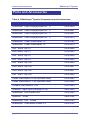
1
User’s Manual & Quick Reference Guide
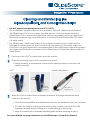
GlideScope® GVL and Cobalt
0900-1204-03-20
GlideScope® GVL and Cobalt
Quick Reference Guide
Corporate Headquarters:
Verathon Inc.
20001 North Creek Parkway,
Bothell, WA 98011 USA
800.331.2313 (Canada and US)
425.867.1348
Fax: 425.883.2896
verathon.com
Verathon Medical (Europe) B.V.
Linnaeusweg 11
3401 MS, IJsselstein
The Netherlands
+31.30.68.70.570
Fax: +31.30.68.70.512
verathon.eu
Verathon Medical (Canada) ULC
4224 Manor Street
Burnaby, BC V5G 1B2
Canada
604.439.3009
Fax: 604.439.3039
For additional contact information please visit our corporate website:
verathon.com.
GlideScope, GVL, GlideRite, and Verathon are trademarks of Verathon
Inc. All other brand and product names are trademarks of their
respective owners.
®
The GlideScope technology is covered under US Patents (6,655,377)
(6,543,447) as well as European Patent 1307131. Additional patents
pending.
Information in this User’s Manual and Quick Reference Guide may
change at any time without notice. For the most up-to-date information,
see the online manuals on www.verathon.com.
®
GlideScope Video Laryngoscope systems are CE marked in
accordance with the Medical Device Directive, and the Verathon Inc.
quality is Quality System Certified to ISO 13485:2003 standards.
© 2009, 2010 Verathon Inc. No part of this manual may be copied or
transmitted by any method without the express written consent of
Verathon Inc.
PN 0900-2100-01-20
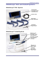
GlideScope® System Quick Start
The monitor may be used immediately by
plugging it into an AC power source, or by
fully charging the battery prior to first use.
To ensure proper charging, follow these steps
in order:
•
Make sure the AC power cord is
disconnected and the power switch is in
the OFF position.
•
Slide the power switch at the back of the monitor to the ON position.
•
Plug the Monitor into an AC power source:
◦
Insert the female end of the power cord into the port on the back
of the Monitor.
•
The charge status LED will turn orange, indicating that the recharging
cycle has begun.
•
When charging is complete, the status LED will turn green. At this
point the unit is fully functional on battery power.
If the AC power cord is inserted before
the power switch is in the ON position, the
charge status LED will flash orange.
Connect the Video Laryngoscope to the
monitor.
•
If using the GVL®:
Connect either end of the video cable
to the GVL® connector. Connect the
video cable to the monitor connector.
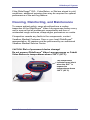
GlideScope® System Quick Start
•
If using the Cobalt system:
STAT
Video
Baton
Connect the video baton
to the monitor as shown for
the GVL® above. Then slide
a single-use GVL® Stat over
the video baton.
To detach a GVL® Stat from a Cobalt Video Baton, grasp the base of
the video baton and pull firmly.
IMPORTANT! A used GVL® Stat is a biohazard and should be disposed of in
compliance with local protocols.
LED State
Meaning
Steady green
The battery is fully charged and ready for use.
CHARGE
STATUS
Flashing orange
CHARGE
STATUS
Flashing orange can indicate two states:
•
•
Steady orange
If the AC power is connected and the power
switch is off ("O" - to the left), the CHARGE
STATUS LED will flash orange. The monitor will still
function but the battery will not charge.
If the AC power is NOT connected and the
CHARGE STATUS LED flashes orange, the battery
is malfunctioning.
Charging in progress
CHARGE
STATUS
Corporate Headquarters:
Verathon Inc.
20001 North Creek Parkway
Bothell, WA 98011, USA
Tel: 800.331.2313 (US and Canada only)
Tel: 425.867.1348 Fax: 425.883.2896
Manufacturer:
Verathon Medical (Canada) ULC
4224 Manor Street
Burnaby, British Columbia
Canada, V5G 1B2
EC Representative:
Verathon Medical (Europe) B.V.
Linnaeusweg 11
3401 MS IJsselstein Netherlands
Tel: +31.30.68.70.570
Fax: +31.30.68.70.512t
www.verathon.com
GlideScope®, GVL®, Verathon® and Verathon Medical® are registered trademarks of Verathon Inc. in the United States and/or other countries.
All rights reserved. Copyright © 2008 by Verathon Inc. GlideScope® video laryngoscope systems are CE marked in accordance with the Medical
0900-2077-01-60
Device Directive, and the Verathon Inc. quality system is Quality System Certified to ISO 13485:2003 standards.
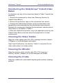
Cleaning and Disinfecting the
GlideScope® GVL and Cobalt Video Baton
• DO NOT expose to temperatures above 60oC (140oF).
Do not disinfect using devices such as autoclaves, ultrasonic cleaners or pasteurizers.
• The GlideScope® GVL is a non sterile, reusable device. It is recommended that the
GlideScope® GVL is cleaned and disinfected after every patient use using a High Level
Disinfectant method. High Level Disinfection is required for the GlideScope® GVL when
it is visibly soiled.
• The GlideScope Cobalt Video Baton is a non sterile, reusable device. When used as
intended, it is protected from direct contact with the patient by the sterile, single-use
GVL® Stat. Low Level Disinfection is recommended for the video baton after every patient
use. High Level Disinfection is required for the GlideScope® Cobalt Video Baton when it is
visibly soiled.
Disconnect the GVL® or video baton from the monitor.
Place the cleaning cap over the connector as shown.
• During cleaning, the protective cap must be inserted as shown to protect the
cable connector.
Cobalt Video Baton
GVL®
GlideScope® Cobalt
Cleaning Cap
Correct
Cleaning
Position
Video Baton
Cleaning Cap
Wash the GVL® or video baton manually to remove all foreign material from the
surface of the device.
• Chemical compatibility and disinfection methods are detailed in the User’s Manual.
• To clean the exterior of the monitor and the video cables, wipe with IPA (70%
isopropyl alcohol) bleach (100ppm) or a mild detergent and water.
• Wipe the cradle with a standard hospital-grade surface cleaning product.
For more detailed cleaning instructions see the GlideScope® System User’s Manual.
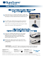
Attaching/Detaching the GlideScope®
GVL or Cobalt Video Baton
Insert the GVL® or Cobalt Video Baton cable into
the port located on the face of the monitor so that
the arrows on the cable and the monitor line up.
For GVL® only: Attach the opposite end of the
video cable to the port located on the GVL®.
Note: When connecting and disconnecting the cable,
grasp the connector by the gray sleeve.
Attaching/Detaching the
GlideScope® Cobalt Video Baton and Stat
Insert the Cobalt Video Baton into the sterile,
single-use GVL® Stat until it clicks into place.
Ensure proper insertion by matching the
GlideScope® logo on the side of the video
baton and the GVL® Stat.
STAT
video
baton
Detach the video baton from the GVL® Stat
by grasping the base of the video baton and
pulling firmly.
IMPORTANT! A used GVL® Stat is a biohazard and should be disposed
of in a manner consistent with local directives in the user’s jurisdiction.
Corporate Headquarters:
Verathon Inc.
20001 North Creek Parkway
Bothell, WA 98011, USA
Tel: 800.331.2313 (US and Canada only)
Tel: 425.867.1348 Fax: 425.883.2896
Manufacturer:
Verathon Medical (Canada) ULC
4224 Manor Street
Burnaby, British Columbia
Canada, V5G 1B2
EC Representative:
Verathon Medical (Europe) B.V.
Linnaeusweg 11
3401 MS IJsselstein Netherlands
Tel: +31.30.68.70.570
Fax: +31.30.68.70.512t
verathon.com
GlideScope, GVL, and Verathon are trademarks of Verathon Inc. © 2008, 2009 Verathon Inc. GlideScope® video laryngoscope systems are CE marked in
accordance with the Medical Device Directive, and the Verathon Inc. quality system is Quality System Certified to ISO 13485:2003 standards.
0900-2013-04-60
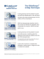
The GlideScope®
4-Step Technique
Looking directly into the patient’s mouth
and with the GlideScope® in the left hand,
introduce the video laryngoscope into the
midline of the oral pharynx.
With the laryngoscope inserted, look to
the monitor to identify the epiglottis, then
manipulate the scope to obtain the best
glottic view.
Looking directly into the patient’s mouth,
not at the screen, carefully guide the
distal tip of the tube into position near the
tip of the laryngoscope.
It is important to look into the mouth at this step to
avoid injuring the tonsils or soft palate.
Look to the monitor to complete the
intubation; gently rotate or angle the tube
to redirect as needed.
GlideScope® video laryngoscope systems are CE marked in accordance with the Medical Device Directive, and the Verathon Inc. quality system
is Quality System Certified to ISO 13485:2003 standards. © 2009 Verathon Inc.
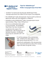
Tips for GlideScope®
Video Laryngoscope Insertion
• Verathon® recommends inserting the GlideScope® Video
Laryngoscope down the midline of the tongue to the epiglottis.
• The GlideScope® video laryngoscope may be used to produce a
MacIntosh indirect lift of the epiglottis or a Miller lift.
• Intubations using GlideScope® Video Laryngoscopes require
approximately 0.5kg-1.5kg of lifting force.
• Use of an endotracheal tube stylet
is recommended. The GlideRite®
Rigid Stylet has been designed to
complement the angle of the
GlideScope® video laryngoscope to
facilitate intubation. A malleable
stylet may be used with a 60°- 90°
angle.
• To aid the passage of the endotracheal
tube, withdraw the stylet (approx. 5 cm)
while gently advancing the ETT. A 1 cm
adjustment (withdrawal) of the laryngoscope
also may be beneficial to reduce the viewing
angle and allow the glottis to drop.
Corporate Headquarters:
Verathon Inc.
20001 North Creek Parkway
Bothell, WA 98011, USA
Tel: 800.331.2313 (US and Canada only)
Tel: 425.867.1348 Fax: 425.883.2896
Verathon Medical
(Canada) ULC
4224 Manor Street
Burnaby, British Columbia
Canada, V5G 1B2
Verathon Medical (Europe) B.V.
Linnaeusweg 11
3401 MS IJsselstein Netherlands
Tel: +31.30.68.70.570
Fax: +31.30.68.70.512
GlideScope, GVL, GlideRite, and Verathon are trademarks of Verathon Inc. © 2009 Verathon Inc. All rights reserved.
verathon.com
0900-1436-06-60
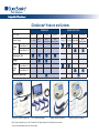
GlideScope® Products and Systems
REUSABLE
GVL® Size
Patient Weight
Cobalt
AVL
SINGLE USE STATS
GVL® 2
GVL® 3
GVL® 4
GVL® 5
GVL® 1
GVL® 2
GVL® 3
GVL® 4
1.8 - 10 kg
10 kg Adult
40 kg Morbidly Obese
40 kg Morbidly Obese
< 3.6 kg
1.8 - 10 kg
10 kg - Adult
40 kg Morbidly Obese
Video Baton 1-2
Video Baton 3-4
GlideScope® GVL
Ranger
Ranger
Single
Use
Video Baton 1-2
Video Baton 3-4
GlideRite® Rigid Stylet *
FPO
Cobalt AVL System (single use)
GVL® System (reusable)
FPO
Ranger System (reusable)
Note: System configurations vary. The Cobalt AVL and Ranger Single Use Video Batons are reusable.
*For use with endotracheal tubes 6.0 mm and larger.
FPO
Ranger Single Use System
GlideScope® Product Specifications
System MONITORS
Cobalt AVL Monitor
REUSABLE SYSTEM COMPONENTS
SINGLE USE SYSTEM COMPONENTS
Cobalt AVL Video Baton 1-2
Cobalt AVL Video Baton 3-4
GVL® 2
GVL® 3
Color, 6.4in (diagonal), VGA 640 x 480
Height: 190 mm
Width: 225 mm
Depth: 80 mm
Weight: 1.0 kg
Length: Camera tip to SS ring to handle: 66mm
Height of camera: 6 mm
Width of camera: 7 mm
Cable length: 194.5 cm
Weight: 170 g
Length: Camera tip to SS ring: 100 mm
Height of camera: 11 mm
Width of camera: 11 mm
Cable length: 193 cm
Weight: 230 g
GVL® Monitor
Ranger Video Baton 1-2
Ranger Video Baton 3-4
GVL® 4
GVL® 5*
Color, 6.4in (diagonal), 440 x 234
Height: 167 mm
Width: 207 mm
Depth: 83 mm
Weight: 1.4 kg
Length: Camera tip to handle: 40 mm
Height of camera: 6 mm
Width of camera: 7 mm
Cable length: 86.4 cm
Weight: 95 g
Length: Camera tip to SS ring: 104.1 mm
Height of camera: 10.7 mm
Width of camera: 10.9 mm
Cable length: 86.4 cm
Weight: 141 g
Blade length (tip to handle): 102 mm
Thickness (height) at camera: 14 mm
Width at camera: 27 mm
Blade length (tip to handle): 102 mm
Thickness (height) at camera: 14 mm
Width at camera: 27 mm
Ranger Monitor
GVL® 1 and 2
GVL® 3 and 4
Ranger GVL® 3
Ranger GVL® 4
Color, 3.4in (diagonal), 480 x 234
Height: 168 mm
Width: 173 mm
Depth: 49 mm
Weight: 0.56 kg
STAT length (tip to handle): 38 mm/51 mm
Thickness (height) at camera: 8.7 mm/8.7 mm
Width at camera: 9.9 mm/10.9 mm
STAT length (tip to handle): 80 mm/95 mm
Thickness (height) at camera: 16 mm/16 mm
Width at camera: 16 mm/20 mm
Blade length (tip to handle): 78mm
Thickness (height) at camera: 14.5 mm
Width at camera: 14 mm
Blade length (tip to handle): 89 mm
Thickness (height) at camera: 14.5 mm
Width at camera: 19 mm
Note: The Cobalt AVL and Ranger Single Use Video Batons are reusable.
20001 North Creek Parkway, Bothell, WA 98011
www.verathon.com
Blade length (tip to handle): 47 mm
Thickness (height) at camera: 14.5 mm
Width at camera: 18 mm
Blade length (tip to handle): 82 mm
Thickness (height) at camera: 14.5 mm
Width at camera: 20mm
*The GVL® 5 is designed to accommodate anatomical anomalies sometimes associated with bariatric patients.
1.800.331.2313 (U.S. & Canada Only) 425.867.1348
The GlideScope video laryngoscopy systems are CE marked in accordance with the Medical Device Directive, and the Verathon Inc. quality system is Quality System Certified to ISO 13485:2003 standards. US Patent No. 6,655,377; 6,543,447; Other patents pending.
GlideScope, GVL and Verathon are trademarks of Verathon Inc. © 2009 Verathon Inc.
0900-2067-03-86
GlideScope® System
Important Information
Statement of Prescription
Federal (USA) law restricts this device for sale by or on the order
of a physician.
®
The GlideScope Video Laryngoscope System should be used
only by individuals who have been trained and authorized by a
physician, or by health care providers who have been trained
and authorized by the institution providing patient care.
Intended Use
®
GlideScope Video Laryngoscopes are intended for use by
qualified medical professionals to obtain a clear, unobstructed
view of the vocal cords for medical procedures.
Warnings and Cautions
Caution. Risk of permanent equipment damage.
®
Do not expose GlideScope Video Laryngoscopes or Cobalt
Video Baton to temperatures above 140° F (60° C). Do not
®
disinfect GlideScope Video Laryngoscopes or Cobalt Video
Batons using devices such as autoclaves, ultrasonic cleaners, or
pasteurizers. Use of such methods will cause permanent device
damage and void the warranty.
Equipment Caution: Electrical shock hazard. Refer servicing
to qualified personnel.
This equipment has been tested and found to comply with the
standards listed in the Approvals section of this manual. These
limits are designed to provide reasonable protection against
harmful interference in typical medical installations.
CAUTION: Risk of equipment damage.
Failure to cover the cable connector port with the protective cap
prior to cleaning may result in water ingress and potential device
failure.
Bleach can be used on the baton but with special attention to the
connector. Bleach may corrode the stainless steel inserts and
damage the connector pins.
CAUTION: Potential interference with other devices.
®
GlideScope Video Laryngoscopes must be used with the
supplied cables to maintain electromagnetic interference (EMI)
within certified limits.
Quick Reference Guide
1
GlideScope® System
®
GlideScope GVL and Cobalt Systems
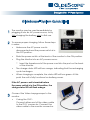
GlideScope® GVL System
®
GlideScope
non-glare color
Video Monitor
Video cable
Reusable
®
GVL (4 sizes)
®
GlideRite
Rigid Stylet
GlideScope® Cobalt System
®
GlideScope
non-glare color
Video Monitor
Reusable Cobalt
Video Batons
(2 sizes)
Single-use
®
GVL Stats
(4 sizes)
®
GlideRite
Rigid Stylet
Quick Reference Guide
2
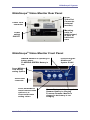
GlideScope® System
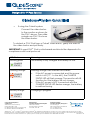
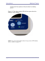
GlideScope® Video Monitor Rear Panel
NTSC
Video Out
Connector
(external
monitor)
Power cord
connector
Mounting
point for
mobile stand,
IV pole, or
hard shell
case
Power
switch
ON/OFF
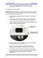
GlideScope® Video Monitor Front Panel
GREEN: Monitor is operating on
battery power
FLASHING GREEN: Battery is
Press to turn the
®
GlideScope
System On/Off
low
Press MENU to
view display
setting options
Video cable
connector
Press UP/DOWN to
move between menu
options or to
increase/decrease
setting values
Quick Reference Guide
GREEN: Battery is fully charged
ORANGE: Battery is charging
FLASHING ORANGE: Monitor is
plugged in but battery is not
charging
3
GlideScope® System
GlideScope® System Configurations
®
The GlideScope System may be configured in one of three
ways to best meet the needs of individual practices. Please refer
to the User’s Manual for complete assembly and setup
information.
Mobile Stand
Hard Shell Case
Mounted on an IV Pole
Preparing for First Use
®
Prior to using the GlideScope system for the first time, perform
the following steps:
1. Charge the monitor battery.
®
2. Set up the GlideScope system in your preferred
configuration.
3. Attach a video laryngoscope or video baton to the
monitor.
4. Connect the monitor to an external source such as a TV
screen (optional).
5. Perform a functional check.
®
a. Connect a GlideScope Video Laryngoscope to the
®
®
monitor (GVL or Cobalt Video Baton + GVL Stat.
b. Turn the system on by pressing the ON/OFF button
located on the face of the monitor.
c.
Observe the monitor screen to verify that an image
®
is being received from the GlideScope .
Quick Reference Guide
4
GlideScope® System
®
If the GlideScope GVL, Video Baton, or Stat are stored in cold
conditions, additional warming time may be required for optimal
performance of the anti-fog feature.
Cleaning, Disinfecting, and Maintenance
To ensure patient safety, users should perform a routine
®
inspection of the GlideScope Video Laryngoscope before every
use to ensure that all endoscopic components are free of
unintended rough surfaces, sharp edges, protrusions or cracks.
If inspection reveals any faults in the components, contact
®
Verathon Medical Customer Care or your local GlideScope
representative. All repairs must be performed by an authorized
Verathon Medical Service Center.
CAUTION: Risk of permanent device damage!
®
Do not expose GlideScope Video Laryngoscopes or Cobalt
Video Batons to temperatures above 140° F (60°C).
The temperature
indicator turns black
®
when the GVL is
exposed to
temperatures above
140° F (60° C)
Quick Reference Guide
5
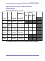
GlideScope® System
General Cleaning and Disinfection
Information
Table 1: Risk Assessment
Disinfection
Device
Sterile
Use
Spaulding’s
CDC
Classification
GVL®
Nonsterile
Reusable
Semicritical
GVL®
Stat
Sterile
Single use
Semicritical
Cobalt
Video
Baton*
Nonsterile
Reusable
Noncritical
X
Video
Cables
Nonsterile
Reusable
Noncritical
X
Stylet
Nonsterile
Reusable
Semicritical
Monitor#
Nonsterile
Reusable
Noncritical
X
Cradle#
Nonsterile
Reusable
Noncritical
X
Low
Level
Int.
Level
High
Level
Sterilization
X
X
It is understood that all items in this chart will be used as intended
Quick Reference Guide
6
GlideScope® System
Key:
*
The Cobalt Video Baton is a nonsterile, reusable device
which is protected from contact with mucous membranes
and non-intact skin by the Stat (sterile, single use) when
used as intended. Low level disinfection is recommended for
the Cobalt Video Baton after every patient use. High Level
Disinfection is required for the Video Baton when it is visibly
soiled.
#
Disinfect monitor and cradle when they are visibly soiled and
on a regular basis as per a schedule established by the
medical care facility or provider.
–
Shaded areas - not required/not compatible with device
materials.
–
Checked boxes (x) show minimum requirement.
–
Unshaded areas show permissible levels of disinfection
based on compatibility with device materials.
Warning:
Disinfectants and cleaning methods listed are recommended by
Verathon based on compatibility with product materials. Refer to
the label instructions for guidance on disinfection efficacy and
appropriate clinical uses.
Caution: Meticulous cleaning must precede any disinfection
process, to ensure all foreign matter is removed from the surface
of the device. This allows the active ingredients of the chosen
process to reach all the surfaces of the device.
Availability of cleaning products varies by country, and we are
unable to test products in every market. Please use the list of
recommended chemicals in this manual to compare with
products available locally.
Quick Reference Guide
7
GlideScope® System
Note: When using any of the chemicals listed below, read and
comply with product use instructions in all applications.
Table 2: Chemical Compatibility and Disinfection
Methods for GVL®, Cobalt Video Batons and Video
Cables
Active
Ingredient
Compatibility
Conditions
Enzymatic
debridement
agent/
detergent
General
hospital grade
Isopropyl
Alcohol Solution
Glutaraldehyde
OrthoPhthalaldehyde
Peracetic Acid
Bleach (Sodium
Hypochlorite)
Disinfection
Level
Caution/
Comments
As per
instructions
N/A
Surface
cleaning only
in preparation
for disinfectant
70%
70% used to
wipe down with
minimum 1
minute exposure
Low
Up to 3.4%
2.0% – exposure
for minimum 20
minutes at 20°C
or as per
manufacturer’s
instructions
High
0.55%
0.55% –
exposure for 12
minutes at 20°C
or as per
manufacturer’s
instructions
High
0.2%
0.2% - exposure
for minimum 12
minutes at 50 to
56°C or as per
manufacturer’s
instructions
See
comments
on right
Classified as
a chemical
sterilant
5000ppm –
exposure for 10
minutes at 20°C
High
Corrosive for
connector pins
and SS ring
500ppm – used
to wipe down
with minimum 1
minute exposure
Low
Noncorrosive
at ≤ 500ppm
Up to
8000ppm
Quick Reference Guide
8
GlideScope® System
Table 3: Chemical Compatibility and Disinfection
Methods for GlideRite® Rigid Stylet
Active
Ingredient
Compatibility
Conditions
Disinfection
Level
Glutaraldehyde
Up to 3.4%
2.0% – exposure
for minimum 20
minutes at 20°C or
as per
manufacturer’s
instructions
High
OrthoPhthalaldehyde
0.55%
0.55% – exposure
for 12 minutes at
20°C or as per
manufacturer’s
instructions
High
Peracetic Acid
0.2%
0.2% - exposure for
minimum 12
minutes at 50 to
56°C or as per
manufacturer’s
instructions
See
comments
on right
Isopropyl
Alcohol Solution
70%
70% - exposure for
10 minutes at 20°C
Intermediate
70% used to wipe
down with
minimum 1 minute
exposure
Low
Caution/
Comments
Classified as a
chemical sterilant
500ppm – used to
wipe down with
minimum 1 minute
exposure
Low
General
hospital grade
As per instructions
N/A
Surface cleaning
only in preparation
for disinfectant
Tested in
autoclave
(steam cycle)
Minimum 4 minute
132°C pre-vacuum
steam sterilization
cycle
See
comments
on right
Based on requests
from users, an
autoclave cycle has
been established
for the Stylet for
ease of use
Bleach (Sodium
Hypochlorite)
≤ 500ppm
Enzymatic
debridement
agent/
detergent
N/A
Quick Reference Guide
Noncorrosive
at ≤ 500ppm
9
GlideScope® System
Cleaning and Disinfecting the GVL® and Cobalt
Video Baton
Caution: Meticulous cleaning must precede any disinfection
process, to ensure all foreign matter is removed from the surface
of the device. This allows the active ingredients of the chosen
process to reach all the surfaces of the device.
®
The GlideScope GVL is a nonsterile reusable device. It is
®
recommended that the GlideScope GVL is cleaned and
disinfected after every patient use, using a High Level
Disinfectant method. High Level Disinfection is required for the
®
GlideScope GVL when it is visibly soiled.
The Cobalt Video Baton is a nonsterile, reusable device which is
protected from direct contact with the patient by the Stat (sterile,
single use) when used as intended, Low level disinfection is
recommended for the Cobalt Video Baton after every patient
use. High Level Disinfection is required for the Cobalt Video
Baton when it is visibly soiled.
CAUTION: Risk of equipment damage.
Bleach can be used on the baton but with special attention to the
connector. Bleach may corrode the stainless steel inserts and
damage the connector pins.
Availability of disinfection products varies by country, and we are
unable to test products in every market. Please use the list of
recommended disinfectants in the User's Manual to compare
with products available locally.
For more detailed cleaning instructions see the GlideScope
System User's Manual or visit
http://www.verathon.com/gs_manuals.htm
Quick Reference Guide
®
10
GlideScope® System
Battery Replacement and Device Repair
Under normal operating conditions, the monitor battery will last 2
- 3 years; or approximately 500 charge/discharge cycles.
The battery is not user-replaceable. In case of battery
malfunction, do not attempt to replace the monitor battery. Any
attempts to replace the battery by unauthorized service
technicians may cause serious harm to the user and will void the
warranty. Please contact your Verathon Medical Customer Care
Representative for more information on battery replacement.
Device Disposal
Disposal of this device can be coordinated through your
Verathon Medical Service Center in accordance with WEEE
requirements.
Quick Reference Guide
11
GlideScope® System
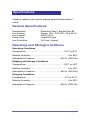
Specifications
General Specifications
Classification:
Line Voltage
Line Current:
Power Plug:
Line Protection:
Electrical Class I, Applied Part BF
Range: 100 – 240 VAC, 50 & 60 Hz
MAX 0.50 A
Hospital Grade
2A Fuse, Internal
Operation and Storage Conditions
Operating Conditions
Temperature:………………………………………...…10°C to 40°C
Relative Humidity:………………………………………......0 to 95%
Atmospheric Pressure:…………………………….440 to 1060 hPa
Shipping and Storage Conditions
Temperature:……………………………..……………-20°C to 45°C
Relative Humidity:………………………………………......0 to 95%
Atmospheric Pressure:…………………………….440 to 1060 hPa
Charging Conditions
Temperature:………………………………………….…0°C to 40°C
Relative Humidity:………………………………………......0 to 95%
Atmospheric Pressure:…………………………….440 to 1060 hPa
Quick Reference Guide
12
GlideScope® System
Standards and Approvals
CMDCAS ISO 13485, Certificate No. 9235, EC Certificate for Class I
sterile Stats, Certificate No. 41315937, MDD Requirements met for
Class I and Class I sterile devices, CSA Requirements met (Master
Contract # 213281), CSA Certificates issued, CB Scheme
requirements met (CB Bulletin 112a), CB Test Certificates issued,
CAN/CSA C22.2 No 601.1-M90, CAN/CSA C22.2 No. 60601-2-1801, UL Std No 60601-1, IEC 60601-2-18, CE Mark EMC Directive,
IEC 60601-1-2, CISPR 11, VCCI Technical V-3
Symbol Directory
The following international regulatory symbols are found on the
GlideScope® Video Laryngoscope and/or GlideScope® Video
Monitor and indicate compliance with international regulatory
standards:
Symbol
Meaning
Type BF equipment
CE marking in accordance with the Medical Device
Directive ( 0413 for Sterile Devices)
Canadian Standards Association (CSA) mark of
certification to applicable standards for electro-medical
equipment
Tested to Federal Communications Commission
Requirements
Attention – consult accompanying documents. Read
instructions before connecting or operating
Subject to WEEE (Waste of Electronic Electrical
Equipment) regulations
Quick Reference Guide
13
GlideScope® GVL and Cobalt
User’s Manual
Corporate Headquarters:
Verathon Inc.
20001 North Creek Parkway,
Bothell, WA 98011 USA
800.331.2313 (Canada and US)
425.867.1348
Fax: 425.883.2896
verathon.com
Verathon Medical (Europe) B.V.
Linnaeusweg 11
3401 MS, IJsselstein
The Netherlands
+31.30.68.70.570
Fax: +31.30.68.70.512
verathon.eu
Verathon Medical (Canada) ULC
4224 Manor Street
Burnaby, BC V5G 1B2
Canada
604.439.3009
Fax: 604.439.3039
For additional contact information please visit our corporate website:
verathon.com.
GlideScope, GVL, GlideRite, and Verathon are trademarks of Verathon
Inc. All other brand and product names are trademarks of their
respective owners.
®
The GlideScope technology is covered under US Patents (6,655,377)
(6,543,447) as well as European Patent 1307131. Additional patents
pending.
Information in this User’s Manual and Quick Reference Guide may
change at any time without notice. For the most up-to-date information,
see the online manuals on www.verathon.com.
®
GlideScope Video Laryngoscope systems are CE marked in
accordance with the Medical Device Directive, and the Verathon Inc.
quality is Quality System Certified to ISO 13485:2003 standards.
© 2009, 2010 Verathon Inc. No part of this manual may be copied or
transmitted by any method without the express written consent of
Verathon Inc.
PN 0900-2101-01-60
GlideScope® GVL and Cobalt
User’s Manual
User’s Manual
page 3
®
Contents
GlideScope System
Contents
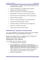
Important Information ............................................................... 7
Product Description ........................................................ 7
Intended Use .................................................................. 7
Statement of Prescription .......................................... 7
Intended Use ............................................................. 7
Notice to All Operators ................................................... 8
Cautions .......................................................................... 8
®
Introducing the GlideScope System .................................... 10
®
GlideScope System Components ............................... 11
®
GlideScope GVL System ....................................... 11
Cobalt Single-Use System ....................................... 12
®
GlideScope System Setup Options ............................ 13
Displays, Controls, and Indicators ........................................ 16
Monitor Back Panel ...................................................... 16
Monitor Front Panel ...................................................... 17
Getting Started ......................................................................... 21
Initial Inspection ............................................................ 21
Preparing for First Use ................................................. 22
Charge the Monitor Battery ..................................... 22
®
Set up the GlideScope System .............................. 25
®
Attaching and Detaching the GlideScope GVL or
®
Cobalt VB and GVL Stat ........................................ 33
Connect the Monitor to an External Video Device ... 38
Perform a Functional Check .................................... 39
Optional Accessory ....................................................... 41
®
®
GlideScope DVR for GVL /Cobalt ......................... 41
page 4
User’s Manual
Playback .................................................................. 41
Troubleshooting ....................................................... 42
Cleaning ................................................................... 42
Clinical Application Tips ................................................ 43
®
The GlideScope 4-Step Technique ........................ 43
®
Tips for GlideScope Video Laryngoscope Insertion....... 43
Tips for Working with Endotracheal Tubes ................... 45
Cleaning, Disinfecting and Maintaining the
®
GlideScope GVL and Cobalt Systems.................................. 46
General Maintenance Information ................................ 46
General Cleaning and Disinfection Information ............ 47
®
Cleaning and Disinfecting GlideScope GVL and
Cobalt Systems............................................................. 51
®
Cleaning the GlideScope GVL .................................... 52
®
Disinfecting the GlideScope GVL ............................... 52
®
Cleaning the GlideScope Cobalt Video Baton ............ 53
®
Disinfecting the GlideScope Cobalt Video Baton ....... 55
Cleaning the Video Cables ........................................... 55
Cleaning the Monitor .................................................... 55
Cleaning the Cradle ...................................................... 55
®
Cleaning and Disinfecting the GlideRite Rigid Stylet .. 56
Replacing the Monitor Battery ...................................... 56
O-Ring Replacement .................................................... 57
Transportation and Storage .......................................... 58
Device Disposal ............................................................ 58
Warranty Offerings .................................................................. 59
Original First Year Total Customer Care
SM
Warranty ... 59
What is Covered ...................................................... 60
Premium Customer Care
User’s Manual
SM
Warranty ...................... 60
page 5
®
Contents
GlideScope System
Disclaimer of Additional Warranties ......................... 60
Contact Information ...................................................... 61
Parts and Accessories ............................................................ 62
Specifications .......................................................................... 64
General Specifications .................................................. 64
Operating and Storage Conditions ............................... 64
®
GlideScope System Components ............................... 65
Standards and Approvals ............................................. 68
Symbol Directory ..................................................................... 69
page 6
User’s Manual
®
GlideScope System
Important Information
Important Information
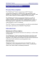
Important Information
Product Description
®
®
The GlideScope Video Laryngoscope (GVL ) System
incorporates a miniature, autofocusing, high-resolution color
camera, an LED light source, a rechargeable lithium battery, and
NTSC video output for remote display or video recording.
®
The GlideScope Video Laryngoscope System is useful for
anterior airways, neonatal intubations, obese patients, and
patients with limited neck extension. Additionally, it is useful for
teaching purposes, verification of endotracheal (ET) position,
nasal intubation, and ET exchange.
®
The GVL System is recommended for use with an endotracheal
®
tube stylet, particularly the GlideRite Rigid Stylet.
Intended Use
Statement of Prescription
Federal (USA) law restricts this device for sale by or on the order
of a physician.
®
The GlideScope Video Laryngoscope System should be used
only by individuals who have been trained and authorized by a
physician or by health care providers who have been trained and
authorized by the institution providing patient care.
Intended Use
®
GlideScope Video Laryngoscopes are intended for use by
qualified medical professionals to obtain a clear, unobstructed
view of the vocal cords for medical procedures
User’s Manual
page 7
®
Important Information
GlideScope System
Notice to All Operators
All operators should read this entire User’s Manual prior to using
®
the GlideScope System. Failure to follow these instructions may
result in patient injury, comprise the performance of the system,
and may void the system warranty.
®
Verathon recommends that new GlideScope users:
®
Practice using the GVL or Cobalt on a mannequin
before clinical use
Acquire clinical experience on patients without airway
abnormalities
Refer to page 43 for recommended techniques.
Cautions
Caution. Risk of permanent equipment damage.
®
Do not expose GlideScope Video Laryngoscopes or
Cobalt Video Batons to temperatures above 140° F
(60° C).
®
Do not disinfect GlideScope Video Laryngoscopes
or Cobalt Video Batons using devices such as
autoclaves, ultrasonic cleaners, or pasteurizers. Use
®
of such methods to disinfect GlideScope Video
Laryngoscopes or Cobalt Video Batons will cause
permanent device damage and void the warranty.
Refer to page 49 for a list of approved cleaning
procedures and products.
MDD Class 1 Equipment Caution: Electrical shock
hazard. Refer servicing to qualified personnel.
This equipment has been tested and found to comply
with the standards listed in the Approvals section of this
manual (page 68). These limits are designed to provide
reasonable protection against harmful interference in
typical medical installations.
page 8
User’s Manual
®
GlideScope System
Important Information
This equipment generates, uses, and can radiate radio
frequency energy and if used properly is very unlikely to
cause harmful interference to any other device(s) in the
vicinity.
However, there is no guarantee that interference will not
occur in a particular installation. Interference can be
determined by turning the equipment on and off. If this
equipment does cause interference with other devices,
try to correct the interference by one or more of the
following measures:
Re-orient or relocate the receiving device
Increase the separation between equipment
Connect the equipment to an outlet on a circuit
different from that to which the other device(s) is
(are) connected
Consult your Verathon Medical Customer Care
representative
NOTE: GlideScope
®
Video Laryngoscopes must be used with the
supplied cables to maintain electromagnetic interference (EMI)
within certified limits.
Users should be aware that portable and mobile equipment
(cellular phones, etc.) may affect medical electrical equipment
and take appropriate precautions during operation.
User’s Manual
page 9
®
Introduction
GlideScope System
Introducing the GlideScope® System
Introducing
the
®
®
GlideScope Video Laryngoscopes (GVL ) are designed for “1st
pass success.” They provide a consistently clear view of a
®
patient’s airway, enabling quick intubation. GlideScope Video
Laryngoscopes are clinically proven to achieve a Cormack1
Lehane Grade I or II view 99% of the time.
®
All GVL models include an integrated, high-resolution, CMOS
camera, LED light source, and a patented anti-fog mechanism.
They connect directly to a color video monitor for real time
®
viewing, video output, and recording. The GlideScope System
®
is available in both, reusable GVL and single-use Cobalt
versions, in a comprehensive range of versions and range of
sizes, allowing clinicians to meet the particular requirements of
patients ranging in size from neonatal infants to morbidly obese
adults.
®
The GlideScope Video Laryngoscope is an ideal tool for
physicians and other healthcare professionals who need to
effectively manage standard to difficult airways. The
®
GlideScope System is easy to learn, use, and teach. It is ideal
for acute care settings and emergency environments. It also
integrates easily into standard ED, OR, ICU, and NICU
applications.
®
GlideScope Video Laryngoscopes may be useful for the
following procedures:
First use intubations, replacing Direct Laryngoscopy (DL)
Normal or restricted oropharyngeal views/visualization
and assessment of the oropharynx
Cormack-Lehane grades I - IV laryngeal views
1 Cooper RM. Cardiothoracic Anesthesia, Respiration and
Airway; Early clinical experience with a new video laryngoscope
(GlideScope®) in 728 patients. Canadian Journal of Anesthesia.
2005; 52: 2: 191–198.
page 10
User’s Manual
®
GlideScope System
Introduction
Trauma airways - excellent when dealing with blood and
secretions in the airway
Airway management in morbidly obese patients
Preterm and neonatal intubations
Patients requiring cervical spine immobilization
Reintubation in Intensive Care Unit (ICU) settings
Supervision and documentation of the laryngoscopy
Nasal tracheal intubation
Insertion of transesophageal echocardiac probes
Laryngoscopic foreign body removal
Awake intubation for difficult airway management
Insertion of double lumen tubes
Teaching the anatomy of the airway
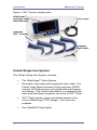
GlideScope® System Components
Two interchangeable video laryngoscope systems are available:
®
the reusable GVL and Cobalt Single-Use System.
Please refer to page 62 for a complete listing of GlideScope
System components and part numbers.
®
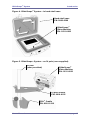
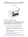
GlideScope® GVL System
®
The GlideScope GVL System includes:
®
The GlideScope Video Monitor
One reusable GVL . The GVL is comprised of a
medical-grade plastic shell that houses a high-resolution
CMOS camera, LED light source, and patented anti®
fogging mechanism. The GVL device is available in four
sizes. Additional units may be purchased separately.
Video cable (connects the GVL to the monitor)
GlideRite Rigid Stylet
®
®
®
User’s Manual
®
page 11
®
Introduction
GlideScope System
®
Figure 1. GVL System components.
®
GlideScope
non-glare color
Video Monitor
Video cable
Reusable
®
GVL (4 sizes)
®
GlideRite
Rigid Stylet
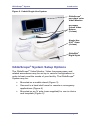
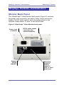
Cobalt Single-Use System
The Cobalt Single-Use System includes:
®
The GlideScope Video Monitor
Reusable video baton with integrated video cable. The
Cobalt Video Baton includes a high-resolution CMOS
camera, LED light source, and a patented anti-fogging
mechanism. The Cobalt Video Baton is available in two
®
sizes and each baton supports two sizes of GVL Stats.
GVL Stats (sterile, single-use blades based on the
®
current GlideScope GVL design) - four sizes are
available
One GlideRite Rigid Stylet
page 12
®
®
User’s Manual
®
GlideScope System
Introduction
Figure 2. Cobalt Single-Use System.
®
GlideScope
non-glare color
Video Monitor
Reusable
Cobalt Video
Batons
(2 sizes)
Single-Use
®
GVL Stats
(4 sizes)
®
GlideRite
Rigid Stylet
GlideScope® System Setup Options
®
The GlideScope Video Monitor, Video Laryngoscopes, and
related accessories may be set up in various configurations in
®
order to best meet the needs of your facility. The GlideScope
System may be:
Mounted on a mobile stand (Figure 3)
Secured in a hard shell case for remote or emergency
applications (Figure 4)
Mounted on an IV pole (user-supplied) for use in clinics
and hospitals (Figure 5)
User’s Manual
page 13
®
Introduction
GlideScope System
®
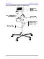
Figure 3. GlideScope System - on mobile stand.
®
GlideScope
Monitor
PN: 0231-0003
®
GVL Video Cable
PN: 0600-0237
®
GVL Cradle
PN: 0810-0126
Cobalt Cradle 3-4
PN: 0810-0134
Cobalt Cradle 1-2
PN: 0810-0151
Mobile Stand
PN: 0800-0299
page 14
User’s Manual
®
GlideScope System
Introduction
®
Figure 4. GlideScope System - in hard shell case.
Hard shell case
PN: 0800-0300
®
GlideScope
Video Monitor
PN: 0231-0003
®
Figure 5. GlideScope System - on IV pole (user-supplied).
IV pole
(user provided)
®
GlideScope
Video Monitor
PN: 0231-0003
IV pole mount
PN: 0810-0125
®
GVL Cradle
PN: 0810-0126
User’s Manual
page 15
Displays, Controls, and Indicators
®
GlideScope System
Displays, Controls, and Indicators
Displays, Controls, and Indicators
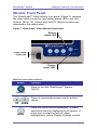
Monitor Back Panel
®
The GlideScope Video Monitor back panel (Figure 6) contains
the power cord connector, accessory video output connector,
battery ON/OFF slider switch, and a mounting point for the
optional mobile stand, IV pole, or hard shell case.
®
Figure 6. GlideScope Video Monitor back panel.
Power cord
connector
Battery
switch
ON/OFF
page 16
NTSC video output
connector (for
external monitor)
Mounting
point for
mobile
stand, IV
pole, or hard
shell case
User’s Manual
®
GlideScope System
Displays, Controls, and Indicators
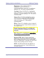
Monitor Front Panel
®
The GlideScope Video Monitor front panel (Figure 7) contains
the video cable connector, two battery status LEDs, and four
buttons: MENU, UP, DOWN, and ON/OFF. Button functions are
described in the table below.
®
Figure 7. GlideScope Video Monitor front panel.
Battery
status LED
Video cable
connector
Charge
status LED
Monitor front panel buttons.
Button
Function
®
Press to turn the GlideScope System
ON/OFF.
ON/OFF
Press to increase/decrease monitor setting
values.
UP
DOWN
MENU
User’s Manual
Press the MENU button repeatedly, to make
selections from the displayed list of options. A
menu item is selected (active) when
highlighted in yellow. Display settings include:
page 17
Displays, Controls, and Indicators
®
GlideScope System
Brightness: When BRIGHTNESS is
highlighted, press UP/DOWN to
increase/decrease luminosity. A brightness
setting of 18 - 20 units is recommended.
Contrast: When CONTRAST is highlighted,
press UP/DOWN to increase/decrease image
contrast. A contrast setting of 16 - 20 units is
recommended.
Color: When COLOR is highlighted, press
UP/DOWN to increase/decrease displayed
color saturation. The default setting of 50
units (on a scale of 0 - 100 units) is
recommended.
Mirror: Press UP to display a mirror image of
the displayed image. Press DOWN to return to
the original view.
Reset: Pressing either UP or DOWN will
return all monitor settings to the factory
defaults.
Exit: When EXIT is highlighted, press either
UP or DOWN to save all settings and return to
the viewing screen.
Normal, NTSC, AV1: These three items
display the format and channel of the signal
®
that is being received from the GlideScope .
®
Since all GlideScope cameras use the NTSC
format, these settings will not change.
NOTE: VOLUME and MUTE may appear on
some monitor screens. These features are
currently inactive.
page 18
User’s Manual
®
GlideScope System
Displays, Controls, and Indicators
Monitor Front Panel LEDs
The monitor front panel has two status LEDs that indicate battery
usage and charge states (Figure 8).
The battery indicator LED illuminates when the monitor
is operating on battery power
The charge status LED indicates the battery charge level
Figure 8. Front panel LEDs indicate battery usage and charge
status.
Battery Indicator LED States
Battery
Indicator LED
No LED
Description
Monitor is off or the battery is completely
depleted and needs to be recharged
Solid Green
Monitor is on and battery level is normal
Flashing Green
Flashing Green indicates two states of low
battery:
● If there is no beeping, there is approximately
five minutes left before the unit turns off due to
low battery.
● If there is beeping, there is approximately
one minute left before the unit turns off due to
low battery.
User’s Manual
page 19
®
Displays, Controls, and Indicators
GlideScope System
Charge Status LED States
Charge
Status LED
Description
No LED
AC power is not connected
Flashing
Orange
Flashing Orange can indicate two states:
● If the AC power is connected, flashing orange
could mean the battery switch is in off (to the
left) position. In this case the monitor will still
function but the battery will not be charged.
● If the AC power is not connected, flashing
orange means the battery is malfunctioning.
Please contact your Verathon Medical
Customer Care representative.
Solid Green
The battery is fully charged
Solid Orange
Charging is in progress
page 20
User’s Manual
®
GlideScope System
Getting Started
Getting Started
Getting Started
Initial Inspection
®
Upon receipt, inspect the components of the GlideScope Video
Laryngoscope System for any obvious physical damage that
may have occurred during shipment. Verathon Medical
recommends that the inspection be performed by a biomedical
engineer or other qualified professional who is familiar with
electronic medical devices.
The components you receive will vary depending on which
configuration was ordered (see Figure 3-5). To verify that you
have received the appropriate components, refer to the packing
list included with your system.
If any of the components are missing or damaged, notify the
carrier and Verathon Medical Customer Care immediately at:
800.331.2313 (Canada and US)
425.867.1348 (International)
+31.30.68.70.570 (Europe)
Please refer to page 61 for additional contact information.
User’s Manual
page 21
®
Getting Started
GlideScope System
Preparing for First Use
®
Prior to using the GlideScope System for the first time, perform
the following steps:
1. Charge the monitor battery (instructions begin on this
page).
®
2. Set up the GlideScope System in your preferred
configuration (instructions begin on page 25).
3. Attach a video laryngoscope to the monitor (instructions
begin on page 33).
4. Connect the monitor to an external source such as a TV
screen or NTSC video monitor (optional).
5. Perform a functional check (instructions begin on
page 39).
1. Charge the Monitor Battery
®
The GlideScope System can operate on AC power (wall
current) or battery power.
®
The GlideScope Monitor contains a lithium battery that provides
®
power to the GlideScope Video Laryngoscope. Under normal
conditions, the battery will last approximately 90 minutes before
it needs to be recharged.
IMPORTANT! The battery must be fully charged prior to first
use.
For optimal battery life:
The battery must be fully charged before first use in
battery mode
When the battery is low, the charge status LED (on the
monitor front panel) will flash green for approximately
five minutes
When the battery is nearly depleted, the charge status
LED will flash green and beep. This indicates that the
battery has approximately one minute of power
remaining.
page 22
User’s Manual
®
GlideScope System
Getting Started
The monitor battery should be charged at room
temperature, between 32° - 104° F (0° - 40° C)
To charge the monitor battery:
IMPORTANT! Before beginning, make sure the AC power cord is
disconnected and the battery switch (on the monitor rear panel)
is in the OFF position (to the left).
1. Slide the battery switch to the ON position (to the right)
(Figure 9).
2. Insert the female end of the power cord into the power
cord connector on the back of the monitor (Figure 9).
Figure 9. Rear panel detail: AC power cord connector and
battery switch in the ON position.
Power cord
connector
Battery switch in
the ON position
3. Insert the other end of the power cord into a wall outlet
or appropriate AC power source.
NOTE: For power supply compatibility information,
please refer to the label on the back of the monitor.
4. The charge status LED will turn orange, indicating that
the charging cycle has begun. When the battery is fully
charged, the charge status LED will turn green
(Figure 10).
User’s Manual
page 23
Getting Started
®
GlideScope System
At this point the system is fully functional on battery
power.
Figure 10. The charge status LED will turn green when the
battery is fully charged.
NOTE: For more information about charge status LED states,
refer to table on page 20.
page 24
User’s Manual
®
GlideScope System
Getting Started
2. Set Up the GlideScope® System
®
The GlideScope System may be set up in one of three
configurations:
On a mobile stand (Figure 3)
In a hard shell case (Figure 4)
On an IV pole (Figure 5)
Setting up the GlideScope® System on the Mobile
Stand
(Refer to Figure 3, page 14)
Attach the center pole to the base (mobile stand only)
1. Remove the hex
bolt and washers
from the bottom of
the pole.
Figure 11. Attaching the mobile
stand base to the center pole hardware stack-up.
2. Insert the bottom
end of the pole into
the top of the base.
3. Flip the base over
and screw the bolt
and washers back
into place to secure
the pole to the
base. To keep the
center pole stable,
be sure to tighten the bolt securely.
User’s Manual
page 25
Getting Started
4. To reinsert the mobile
stand wheels: insert
the wheel pin into the
opening on the end of
the mobile stand base
(Figure 12). Applying
steady, moderate
force, press the wheel
pin into the base until it
snaps into place.
®
GlideScope System
Figure 12. Removing and
inserting the wheels from the
mobile stand.
To Remove the Mobile
Stand Wheels
The mobile stand wheels may be removed to facilitate
storage and transportation.
Using steady, moderate force, pull the wheels away from
the base.
Adjust the Height of the Mobile Stand (Figure 13)
1. Loosen the black height adjustment knob located on the
mobile stand pole by turning it counterclockwise.
2. Raise or lower the pole to the desired height.
3. Secure the pole in position by turning the height
adjustment knob clockwise.
page 26
User’s Manual
®
GlideScope System
Getting Started
Figure 13. Adjusting the height of the mobile stand.
Attach the Monitor to the Mobile Stand
Hold the monitor against the screw on the tilt head and turn
the tilt head fastener clockwise to tighten (Figure 14).
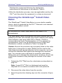
Adjust the Monitor Angle
Before use, the angle of the monitor should be adjusted for
optimal viewing. The ideal angle will be determined by the
working position of the monitor and the user.
To adjust the angle of the monitor:
1. Loosen the angle adjustment knob located on the tilt
head of the IV pole mount by turning it counterclockwise.
2. Tilt the monitor to the desired angle.
3. Secure the monitor in place by turning the angle
adjustment knob clockwise (Figure 14).
User’s Manual
page 27
®
Getting Started
GlideScope System
Figure 14. Attaching the monitor to the mobile stand.
Angle
adjustment
knob
Tilt head
fastener
®
Attach the GVL Cradle
®
To attach the GVL Cradle:
1. Open the cradle latch and position the mobile stand pole
on the back of the cradle.
2. Close the cradle latch and tighten in place by turning the
black cradle adjustment knob clockwise (Figure 15).
Figure 15. Attaching the GVL
Cradle to the mobile stand.
page 28
®
®
Figure 16. GlideScope
®
GVL s in the cradle bays.
User’s Manual
®
GlideScope System
Getting Started
Attach the Cobalt Video Baton Cradle
The Cobalt Video Baton Cradle may be mounted either to
®
the GVL Cradle or directly to the mobile stand center pole.
®
To attach the Cobalt Video Baton Cradle to the GVL Cradle:
®
1. Attach the GVL Cradle to the mobile stand as shown in
Figure 15.
®
2. Hook the Cobalt Cradle into the GVL Cradle as shown
in Figure 17.
Figure 17. Attaching the Cobalt Video Baton Cradle to the
®
GVL Cradle.
To attach the Cobalt Video Baton cradle directly to the
mobile stand or IV pole:
1. Attach the center pole clamp to the Cobalt Cradle.
2. Attach the center pole clamp and Cobalt Video Baton
Cradle to the mobile stand or IV pole and turn the black
knob clockwise to tighten.
User’s Manual
page 29
®
Getting Started
GlideScope System
Figure 18. Attaching the center pole clamp to the Cobalt
Cradle.
Mobile stand
clamp
Mobile stand
pole
Setting up the GlideScope® System in the Hard Shell
Case
Refer to Figure 19 on page 31.
The hard shell case comes with a custom foam insert designed
®
to protect the GlideScope System components. To secure the
monitor in the hard shell case:
1. Remove the foam insert from the bottom of the hard
shell case.
2. Remove the screw from the foam insert.
3. Align the foam insert with the monitor rear panel so that
the battery switch remains accessible.
4. Screw the foam insert to the monitor until the screw is
snug (Figure 19). Do not over-tighten the screw.
page 30
User’s Manual
®
GlideScope System
Getting Started
Figure 19. Removing the video monitor from the hard shell
case.
Removing the Video Monitor From the Hard Shell Case
To remove the monitor from the hard shell case:
1. Grasp the monitor handle and pull the monitor and foam
out of the hard shell case.
2. On the back of the foam insert, remove the screw
holding the monitor to the foam.
User’s Manual
page 31
®
Getting Started
GlideScope System
Setting up the GlideScope® System on an IV Pole
Refer to Figure 5.
1. Attach the IV pole
mounting bracket to
the IV pole by
tightening the bracket
attachment knob until
the bracket is secure.
2. To attach the
®
GlideScope Video
Monitor: hold the
monitor against the
screw on the tilt head
and turn the tilt head
fastener clockwise to
tighten (Figure 14).
Figure 20. Attaching the
mounting bracket to the IV
pole.
Bracket
attachment knob
Tilt head fastener
®
3. To attach a GVL Cradle to the IV pole, refer to
Figure 15.
To attach a Cobalt Video Baton Cradle to the IV pole
refer to Figure 17 or Figure 18.
page 32
User’s Manual
®
GlideScope System
Getting Started
3. Attaching and Detaching the GlideScope® GVL
or Cobalt Video Baton and GVL® Stat
Attaching the GlideScope® GVL to the Monitor
®
The GlideScope GVL connects to the monitor with a detachable
video cable (supplied).
®
1. Insert the GVL Video Cable into the connector port
located on the face of the monitor so that the arrows on
the cable and the monitor are aligned (Figure 21).
NOTE: When connecting and disconnecting the cable,
grasp the connector by the gray sleeve.
®
Figure 21. Attaching the GVL Video Cable to the monitor.
®
GVL Connector Port
2. Insert the other end of the cable into the port located on
®
the handle of the GVL (Figure 22).
User’s Manual
page 33
®
Getting Started
GlideScope System
®
Figure 22. Attaching the video cable to the monitor and GVL .
®
GVL Connector Port
®
NOTE: Visually inspect the GVL to assure that all surfaces
are free of unintended rough areas, sharp edges,
protrusions, or cracks.
Attaching the Cobalt Video Baton to the Monitor
The Cobalt Video Baton includes an integrated video cable. To
attach it to the monitor, insert the video cable connector into the
port located on the face of the monitor so that the arrows on the
cable and the monitor are aligned as shown in Figure 21.
NOTE: When connecting and disconnecting the connector cable,
grasp the cable by the gray sleeve (Figure 21).
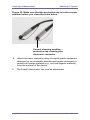
Inserting the Cobalt Video Baton into the GVL® Stat
The Cobalt reusable Video Baton is used with a sterile, single®
use, GVL Stat.
®
Cobalt Video Baton 1-2 is used with GVL Stats 1 and 2
Cobalt Video Baton 3-4 is used with GVL Stats 3 and 4
page 34
®
User’s Manual
®
GlideScope System
Getting Started
®
To insert the Cobalt Video Baton into the GVL Stat:
®
1. Insert the Cobalt Video Baton into the GVL Stat until it
clicks into place (Figure 23).
Figure 23. Inserting the Cobalt Video Baton into the
®
GVL Stat.
®
GVL Stat
Cobalt Video Baton
2. Ensure proper insertion by aligning the wide collar of the
®
video baton to the wide collar of the GVL Stat; or match
®
the GlideScope logo on the side of the video baton with
®
®
GlideScope logo on the side of the GVL Stat.
Be sure not to insert the video baton backwards
(Figure 24). If the video baton does become stuck, insert
®
a tongue depressor into the GVL Stat shell to release
the video baton.
User’s Manual
page 35
®
Getting Started
GlideScope System
Figure 24. Do not insert the video baton backwards.
®
NOTE: Visually inspect the GVL Stat to ensure that all
exterior surfaces are free of unintended rough areas,
sharp edges, protrusions, or cracks.
®
Detaching the Cobalt Video Baton from the GVL Stat
®
The GVL Stat is a single-use device. After each use, it
should be removed from the Cobalt Video Baton and
disposed of properly.
®
To detach the Cobalt Video Baton from the GVL Stat, grasp
the handle of video baton and pull firmly (Figure 25).
page 36
User’s Manual
®
GlideScope System
Getting Started
®
Figure 25. Detaching the video baton from the GVL Stat.
®
IMPORTANT! A used GVL Stat is a biohazard and
should be disposed of in a manner consistent with local
directive’s in the user’s jurisdiction.
GlideScope® Anti-Fog Feature
To ensure optimal results of the anti-fog heating feature on the
®
GlideScope Video Laryngoscope perform the following steps:
Single Use Model
®
If using the GlideScope Cobalt model, follow steps 1, 2 and 3
recommended below.
Reusable Models
®
®
If using the GlideScope GVL model, attach the GVL to the
system then follow steps 2 and 3.
®
1. Prior to use, open the GVL Stat pouch, but do not
remove the Stat from the packaging (to keep the Stat
clean until ready for use). With the Stat still in the
package, insert the Cobalt video baton into the Stat. The
®
video baton must be securely seated in the GVL Stat
for efficient heating of the Stat.
®
2. Turn on the GlideScope monitor to activate the anti-fog
heating feature.
User’s Manual
page 37
®
Getting Started
GlideScope System
3. After 30 seconds to 120 seconds, the anti-fog feature
should be fully effective, depending on the ambient
temperature and humidity where the equipment is being
stored and/or used.
®
If the GlideScope GVL, Video Baton or Stat are stored in cold
conditions, additional warming time may be required for optimal
performance of the anti-fog feature.
4. Connect the Monitor to an External Video
Device (Optional)
The monitor may be connected to an NTSC-compatible
external device such as a TV screen or video recorder by
using an optional Verathon video output cable. Please
contact your Verathon Medical Customer Care
Representative for more information.
To connect the monitor to an external video device:
1. Insert the video output cable into the port on the back of
the video monitor.
2. Connect the opposite end of the cable to the external
viewing device.
page 38
User’s Manual
®
GlideScope System
Getting Started
Figure 26. Attaching a video output cable to the monitor.
To external device
5. Perform a Functional Check
Prior to first use, perform the following functional check to assure
®
that the GlideScope System is working properly. Please contact
your Verathon Medical Customer Care Representative if your
®
GlideScope System does not function as described below.
®
To perform a functional check of the GlideScope System:
1. Fully charge the monitor battery (see page 22).
®
2. Connect a GlideScope Video Laryngoscope to the
®
®
monitor (GVL or Cobalt Video Baton + GVL Stat, see
page 33).
3. Slide the battery switch on the back of the monitor to the
ON (to the right) position.
4. Turn the system on by pressing the ON/OFF button
located on the face of the monitor.
User’s Manual
page 39
®
Getting Started
GlideScope System
5. Observe the monitor screen to verify that an image is
®
being received from the GlideScope (Figure 27).
NOTE: The upper left corner of the LCD screen will
®
display a small portion of the GVL Blade (Figure 27).
The blade is captured in the view due to the wide-angle
properties of the camera lens. This opaque portion acts
as a frame of reference during the intubation process
and assures that the orientation of the image is correct in
the monitor.
®
Figure 27. When the power is on, one corner of the GVL blade
is visible in the display.
Portion of GlideScope®
blade (frame of reference)
page 40
User’s Manual
®
GlideScope System
Getting Started
Optional Accessory
GlideScope® DVR for GVL®/Cobalt
®
The GlideScope DVR (Digital Video Recorder) is designed to
®
record intubations performed with the GlideScope GVL/Cobalt.
Figure 28. GlideScope® DVR
INSTRUCTIONS FOR USE
Recording
1. Ensure Monitor is OFF and SD
card no larger than 2GB is inserted
into the DVR.
®
2. Connect GVL /Video Baton
cable to DVR
3. Connect DVR cable to Monitor
4. Turn Monitor ON
5. REC LED will light up in solid
RED after approximately 3 seconds
6. DVR begins recording automatically
Playback
1. Turn the Monitor OFF and wait
until REC LED turns OFF
(approximately 3 seconds)
2. Open DVR door and remove SD card by
pushing and releasing.
3. Insert the SD card in an SD card reader
connected to a PC
4. Browse to the DVMPG4 folder in SD
card drive
5. Playback any recordings with .ASF extensions
User’s Manual
page 41
Getting Started
®
GlideScope System
Troubleshooting
If REC LED is blinking, there may be a problem with
recording. Possible causes:
1. Connections are not secure. Verify cable connections:
®
GVL /Video Baton to DVR
DVR to Monitor
2. SD card is missing or not inserted properly. Turn Monitor OFF;
ensure SD card is properly inserted and try again.
3. SD card is defective. Try another SD Card.
®
4. Problem with GVL /Video Baton. Ensure proper
®
function by connecting GVL /Video Baton
directly to monitor.
If the problem persists, contact Verathon Medical Customer Care.
Cleaning
Clean the exterior of the DVR with IPA (70% Isopropyl Alcohol
Solution) wipes.
page 42
User’s Manual
®
GlideScope System
Getting Started
Clinical Application Tips
The GlideScope® 4-Step Technique
®
Verathon recommends using the GlideScope 4-Step Technique
as outlined below:
1. In the Mouth: looking directly into the patient’s mouth
®
and with the GlideScope GVL in the left hand, introduce
the GlideScope® Video Laryngoscope into the midline of
the oral pharynx.
2. At the Screen: With the laryngoscope inserted, look at
the monitor to identify the epiglottis, then manipulate the
scope to obtain the best glottic view.
3. In the Mouth: looking directly into the patient’s mouth,
not at the screen, carefully guide the distal tip of the tube
into position near the tip of the laryngoscope.
4. At the Screen: Look to the monitor to complete the
intubation; gently rotate or angle the tube to redirect as
needed.
Tips for GlideScope® Video Laryngoscope
Insertion
®
The GlideScope GVL is designed to be inserted down
the midline of the tongue to the epiglottis.
®
The GlideScope GVL may be used to produce a
Macintosh indirect lift of the epiglottis, or a Miller lift.
®
Intubations using the GlideScope GVL only require
approximately 0.5 - 1.5 kg (1 to 3.5 lbs) of lifting force.
User’s Manual
page 43
Getting Started
®
GlideScope System
The use of an endotracheal tube stylet is recommended.
®
The GlideRite Rigid Stylet has been designed to
®
complement the angle of the GVL to facilitate
intubation, and should be used with endotracheal tubes
6.0mm and larger. A malleable stylet may be used with
a 60° - 90° angle.
To aid the passage of the endotracheal tube when at the
vocal cords, gradually withdraw the stylet approximately
5 cm (2 inches). A 1cm adjustment (withdrawal) of the
laryngoscope may be beneficial to reduce the viewing
angle and allow the glottis to drop.
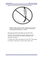
®
Figure 29. The curvature of the GlideRite Rigid Stylet
®
®
complements that of the GVL and GVL Stat.
page 44
User’s Manual
®
GlideScope System
Getting Started
Tips for Working with Endotracheal Tubes
Insert the ET tube behind or immediately adjacent to the
®
GVL Stat.
Do not insert the stylet into the larynx during intubation.
You can bend the proximal tip of the stylet backward to
permit one-handed operation of the ET tube.
Carefully introduce the distal end of the ET tube between
the vocal folds.
®
When introducing the GlideScope and/or the
endotracheal tube, look directly into the mouth to avoid
damaging the endotracheal tube cuff, the patient’s teeth,
or the soft tissues such as the soft palate or tonsils.
Advance the ET tube while simultaneously withdrawing
the stylet with the thumb (Figure 30). The stylet should
be withdrawn approximately 5 cm (2in).
Avoid excessive lifting or pushing of the glottis by the
®
GVL Stat. Maximum laryngeal exposure may not
facilitate intubation; reducing the elevation applied to the
laryngoscope may make inserting the ET tube easier.
®
Figure 30. The GlideRite Rigid Stylet is designed for onehanded removal from the endotracheal tube.
User’s Manual
page 45
®
Cleaning and Maintenance
GlideScope System
Cleaning, Disinfecting and Maintenance
Cleaning, Disinfecting and Maintaining
GlideScope® GVL and Cobalt Systems
®
Cleaning the GlideScope GVL and Cobalt system is an
important part of maintaining the system. Make sure that the
system is clean before each use. You should also examine the
system periodically to make sure it is operating correctly.
General Maintenance Information
Periodic inspections should be performed to ensure safe and
effective operation. It is recommended that a qualified technician
perform a full visual inspection of all components at least every
three months.
The technician should check for the following items:
External damage
Damage to the power supply
Connectors and cable insulation integrity
To ensure patient safety, users should perform a routine
®
inspection of the GlideScope Video Laryngoscope before every
use to ensure that all endoscopic components are free of
unintended rough surfaces, sharp edges, protrusions or cracks.
If inspection reveals any faults in the components, contact
Verathon Medical Customer Care. All repairs must be performed
by an authorized Verathon Medical Service Center.
Caution. Risk of permanent equipment damage.
®
Do not expose GlideScope Video
Laryngoscopes or Cobalt Video Batons to
temperatures above 140° F (60°C). Do not
®
disinfect GlideScope Video Laryngoscopes or
Cobalt Video Batons using devices such as
autoclaves, ultrasonic cleaners, or pasteurizers.
Use of such methods will cause permanent
device damage and void the warranty. Refer to
cleaning section for a list of approved cleaning
procedures and chemicals.
page 46
User’s Manual
®
GlideScope System
Cleaning and Maintenance
General Cleaning and Disinfection
Information
Table 1: Risk Assessment
Device
Sterile
Use
Spaulding’s
CDC
Classification
Disinfection
Low
Level
GVL®
Nonsterile
Reusable
Semicritical
GVL®
Stat
Sterile
Single
use
Semicritical
Cobalt
Video
Baton*
Nonsterile
Reusable
Noncritical
X
Video
Cables
Nonsterile
Reusable
Noncritical
X
Stylet
Nonsterile
Reusable
Semicritical
Monitor#
Nonsterile
Reusable
Noncritical
X
Cradle#
Nonsterile
Reusable
Noncritical
X
Int.
Level
Sterilization
High
Level
X
X
It is understood that all items in this chart will be used as intended.
User’s Manual
page 47
Cleaning and Maintenance
®
GlideScope System
Key:
*
The Cobalt Video Baton is a non sterile, reusable device
which is protected from contact with mucous membranes
and non-intact skin by the Stat (sterile, single use) when
used as intended. Low level disinfection is recommended for
the Cobalt Video Baton after every patient use. High Level
Disinfection is required for the Video Baton when it is visibly
soiled.
#
Disinfect monitor and cradle when they are visibly soiled and
on a regular basis as per a schedule established by the
medical care facility or provider.
–
Shaded areas - not required/not compatible with device
materials.
–
Checked boxes (x) show minimum requirement.
–
Unshaded areas show permissible levels of disinfection
based on compatibility with device materials.
Warning:
Disinfectants and cleaning methods listed are recommended by
Verathon based on compatibility with product materials. Refer to
the label instructions for guidance on disinfection efficacy and
appropriate clinical uses.
Caution: Meticulous cleaning must precede any disinfection
process, to ensure all foreign matter is removed from the surface
of the device. This allows the active ingredients of the chosen
process to reach all the surfaces of the device.
Availability of cleaning products varies by country, and we are
unable to test products in every market. Please use the list of
recommended chemicals in this manual to compare with
products available locally.
Note: When using any of the chemicals listed below, read and
comply with product use instructions in all applications.
page 48
User’s Manual
®
GlideScope System
Cleaning and Maintenance
Table 2: Chemical Compatibility and
Disinfection Methods for GVL®, Cobalt
Video Batons and Video Cables
Active
Ingredient
Compatibility
Conditions
Disinfection
Level
Caution/
Comments
Enzymatic
debridement
agent/
detergent
General
hospital grade
As per
instructions
N/A
Surface
cleaning only
in preparation
for disinfectant
Isopropyl
Alcohol Solution
70%
70% used to
wipe down with
minimum 1
minute exposure
Low
Up to 3.4%
2.0% – exposure
for minimum 20
minutes at 20°C
or as per
manufacturer’s
instructions
High
0.55%
0.55% –
exposure for 12
minutes at 20°C
or as per
manufacturer’s
instructions
High
0.2%
0.2% - exposure
for minimum 12
minutes at 50 to
56°C or as per
manufacturer’s
instructions
See
comments
on right
Classified as a
chemical
sterilant
5000ppm –
exposure for 10
minutes at 20°C
High
Corrosive for
connector pins
and SS ring
500ppm – used
to wipe down
with minimum 1
minute exposure
Low
Noncorrosive
at ≤ 500ppm
Glutaraldehyde
OrthoPhthalaldehyde
Peracetic Acid
Bleach (Sodium
Hypochlorite)
Up to
8000ppm
Refer to pages 51-55 for Disinfecting Steps.
User’s Manual
page 49
®
Cleaning and Maintenance
GlideScope System
Table 3: Chemical Compatibility and
Disinfection Methods for GlideRite® Rigid Stylet
Active
Ingredient
Compatibility
Conditions
Disinfection
Level
Glutaraldehyde
Up to 3.4%
2.0% – exposure for
minimum 20 minutes
at 20°C or as per
manufacturer’s
instructions
High
OrthoPhthalaldehyde
0.55%
0.55% – exposure
for 12 minutes at
20°C or as per
manufacturer’s
instructions
High
Peracetic Acid
0.2%
0.2% - exposure for
minimum 12 minutes
at 50 to 56°C or as
per manufacturer’s
instructions
See comments
on right
Isopropyl
Alcohol Solution
70%
70% - exposure for
10 minutes at 20°C
Intermediate
70% used to wipe
down with minimum
1 minute exposure
Low
Caution/
Comments
Classified as a
chemical
sterilant
500ppm – used to
wipe down with
minimum 1 minute
exposure
Low
General
hospital grade
As per instructions
N/A
Surface
cleaning only in
preparation for
disinfectant
Tested in
autoclave
(steam cycle)
Minimum 4 minute
132°C pre-vacuum
steam sterilization
cycle
See comments
on right
Based on
requests from
users, an
autoclave cycle
has been
established for
the Stylet for
ease of use
Bleach (Sodium
Hypochlorite)
≤ 500ppm
Enzymatic
debridement
agent/ detergent
N/A
Noncorrosive at
≤ 500ppm
Refer to pages 51-55 for Cleaning & Disinfecting Steps.
page 50
User’s Manual
®
GlideScope System
Cleaning and Maintenance
Cleaning and Disinfecting the GlideScope®
GVL and Cobalt Systems
Warning
®
Make sure that you do not overheat the GlideScope GVL or
Cobalt Video Baton during cleaning. You can monitor the color of
the temperature gauge on the handle to avoid overheating the
®
GVL or Cobalt Video Baton.
Caution. Risk of permanent equipment damage.
®
Do not expose GlideScope GVL or Cobalt Video Batons to
temperatures above 140° F (60°C).
The manufacturer’s warranty is void if the product is exposed to
temperatures above 60°C (140°F).
Figure 31. Monitor the color of the temperature indicator to
®.
avoid overheating the GVL
Temperature indicator
®
The temperature indicator turns black if the GVL or
Cobalt Video Baton is heated above 60°C (140°F).
A gray or white indicator does not indicate overheating.
User’s Manual
page 51
®
Cleaning and Maintenance
GlideScope System
Caution
Do not use autoclaves or pasteurizers for the GlideScope® GVL
and Cobalt Systems
Use of such methods will cause permanent device damage and
void the warranty.
Bleach can be used on the baton but with special attention to the
connector. Bleach may corrode the stainless steel inserts and
damage the connector pins.
Cleaning the GlideScope® GVL
®
The GlideScope GVL is a non sterile reusable device. It is
®
recommended that the GlideScope GVL is cleaned and
disinfected after every patient use, using a High Level
Disinfectant method as defined in Table 2. High Level
®
Disinfection is required for the GlideScope GVL when it is visibly
soiled.
®
To clean the GlideScope GVL:
®
1. Disconnect the GVL from the video cable.
2. Insert the attached protective cap into the video cable port to
protect the electronic connector.
®
3. Wash the GVL manually using a hospital grade equipment
detergent or an enzymatic debridement agent/detergent to
remove all foreign material (e.g., soil and organic material) from
the surface of the device.
Disinfecting the GlideScope® GVL
To disinfect use any of the chemicals listed in Table 2 and do the
following:
1.Ensure the equipment is clean (see Cleaning Section for
GVL®).
2.Ensure the protective cap on the connector is secure.
3.Prepare the disinfectant solution at the concentration and
temperature recommended by the disinfectant manufacturer.
page 52
User’s Manual
®
GlideScope System
Cleaning and Maintenance
Disinfect the equipment following the disinfectant
manufacturer’s instructions or as stated in Table 2.
4.After the disinfection process, rinse (as applicable) and dry the
GVL® and then store the equipment in a clean environment.
Cleaning the GlideScope® Cobalt Video
Baton
®
The GlideScope Cobalt Video Baton is a non sterile reusable
device, which is protected by the GVL® Stat and is not intended
to have direct patient contact.
Caution
Do not place the Cobalt Video Baton in the cradle if it is
contaminated.
The video baton, which is protected from direct contact with the
patient by the Stat, will normally only require cleaning and wiping
down between uses using either IPA or bleach. If there is
concern about its level of contamination, or if it is exposed to
contamination, then it can be disinfected using a High Level
Disinfection method, as defined in Table 2 on page 49.
Caution: Ensure the protective cap is properly fitted on the video
baton prior to immersion in water. Bleach can be used on the
video baton but with special attention to the connector, as it may
corrode the stainless steel inserts and damage the connector
pins. You can also use a soft brush to scrub the video baton,
taking care not to damage the camera lens. However, do not use
a wire brush because it may damage the surface of the video
baton.
1. Detach the GVL®Stat from the video baton as described on
page 36.
Note: A used GVL® Stat is a biohazard and must be
disposed of in a manner consistent with local protocols.
2. Disconnect the video baton from the monitor.
3. Place the protective cleaning cap over the connector (Figure
32).
User’s Manual
page 53
Cleaning and Maintenance
®
GlideScope System
Figure 32. Make sure that the protective cap is in the correct
position before you clean the video baton.
Correct cleaning position –
protective cap covering the
electronic connector
4. Wash the baton manually using a hospital-grade equipment
detergent or an enzymatic debridement agent/ detergent to
remove all foreign material (e.g., soil and organic material)
from the surface of the device.
5.
The Cobalt video baton can now be disinfected.
page 54
User’s Manual
®
GlideScope System
Cleaning and Maintenance
Disinfecting the GlideScope® Cobalt Video
Baton
To disinfect use any of the chemicals listed in Table 2 and do the
following:
1. Ensure the equipment is clean (see Cleaning Section for
Cobalt Video Baton).
2. Ensure the protective caps on the connectors are secure.
3. Prepare the disinfectant solution at the concentration and
temperature recommended by the disinfectant manufacturer.
Disinfect the equipment following the disinfectant manufacturer’s
instructions or as stated in Table 2.
4. After the disinfection process, rinse (as applicable) and dry the
Cobalt Video Baton and then store the equipment in a clean
environment.
Cleaning the Video Cables
Wipe the video cables with IPA (70% isopropyl alcohol), bleach
(100ppm) or a mild detergent and water.
High Level Disinfection, as stated in Table 2 is required for the
video cable when it is visibly soiled.
Cleaning the Monitor
Wipe the exterior of the monitor with IPA (70% isopropyl
alcohol), bleach (100ppm) or a mild detergent and water.
Cleaning the Cradle
Wipe the cradle with a standard hospital-grade surface cleaning
product.
User’s Manual
page 55
Cleaning and Maintenance
®
GlideScope System
Cleaning and Disinfecting the GlideRite®
Rigid Stylet
The Stylet is a nonsterile reusable device which requires
cleaning and High Level Disinfection as defined in the risk
analysis – Table 1 on page 47.
1. Clean using a Low Level disinfection wipe method or rinse/
brush method.
2. Using a brush, apply detergent or an enzymatic debridement
agent.
3. Rinse under clean, running water for 1 minute.
4. Disinfect the Stylet using a High Level Disinfection method
as defined in Table 3 on page 50.
Note: For end user convenience it has been determined that the
®
GlideRite Rigid Stylet is compatible with the autoclaving cycle in
Table 3 on page 50.
Replacing the Monitor Battery
Under normal operating conditions, the battery will last 2 - 3
years; or approximately 500 charge/discharge cycles.
The battery is not user-replaceable. In case of battery
malfunction, do not attempt to replace the monitor battery. Any
attempts to replace the battery by unauthorized service
technicians will void the warranty. Please contact your
Verathon Medical Customer Care Representative for more
information on battery replacement.
page 56
User’s Manual
®
GlideScope System
Cleaning and Maintenance
O-Ring Replacement
®
A protective cap is attached to the top of the GlideScope GVL
and on the end of the Cobalt Video Baton cable. The protective
cap contains a rubber O-ring that ensures an effective seal
during cleaning and sterilization. Over time, routine use will wear
out the O-ring. Replace the O-ring immediately if:
Any nicks or tears are visible
There is any liquid in the cable connector port after
cleaning
To replace an O-ring:
®
1. Remove the protective cap from the GVL port.
2. On the inside of the protective cap, pick the O-ring out of
the groove located at the base of the cap and remove.
3. Then stretch the replacement O-ring around the base of
the cap and insert it into the groove (Figure 33). Make
sure it is seated securely in the groove. Take care not to
nick the O-ring during insertion.
Figure 33. Replacing the O-Ring.
O-ring
PN 0120-0335
User’s Manual
page 57
Cleaning and Maintenance
®
GlideScope System
Transportation and Storage
®
GlideScope System components can be safely used and stored
under the environmental conditions specified on page 64.
Figure 34. Prior to shipping, make sure the battery switch is in
the OFF position.
IMPORTANT: The battery switch must be in the OFF (left
side) position during shipping and storage.
Device Disposal
Disposal of this device can be coordinated through your
Verathon Medical Service Center in accordance to the WEEE
requirements.
page 58
User’s Manual
®
GlideScope System
Warranty
GlideScope® Warranty Offerings
Warranty Offerings
Original First Year Total Customer CareSM
Warranty
®
Verathon warrants the GlideScope System against defects in
material and workmanship. This warranty applies for one (1) year
from the date of shipment from Verathon. This warranty is given
®
only to the original purchaser of the GlideScope System.
If a customer’s system requires service or repair, Verathon will
either replace or provide a loaner unit within one (1) business
day from the date of customer service notification. The customer
agrees to send the defective unit to Verathon upon receipt of the
loaner or replacement unit and agrees to return the loaner unit
within two (2) business days of receipt of the repaired unit.
This warranty provides coverage for damage from
accidental drops or mishandling. It does not cover
damage due to deliberate mishandling.
This warranty does not apply if the product has been
damaged due to, or as the result of, service or
modification by anyone other than an authorized
Verathon Service Center.
This warranty does not apply if there is evidence of the
equipment being exposed to temperatures in excess of
60º C.
The product shall be used in accordance with the instructions
contained in this User’s Manual. Consumable items (i.e.,
endotracheal tubes, Stats, stylets, etc.) shall be used in
conformance to Verathon product specifications. Consumable
items are not covered under this warranty.
User’s Manual
page 59
®
Warranty
GlideScope System
What is Covered
®
Warranty coverage is extended to the GlideScope GVL System:
Video Monitor including Display Connector Cable and
Video output Cable (VOC)
o
VOC is only covered with an extended warranty
for the monitor
®
®
GlideScope Video Laryngoscopes (GVL )
Cobalt Video Batons
®
Additional GVL laryngoscopes purchased either singularly or as
a part of a system must be warranted separately.
Additional video monitors purchased either singularly or as part
of a system must be warranted separately.
Premium Customer CareSM Warranty
The Premium Customer CareSM warranty from Verathon Medical
may be extended for a total of up to six (6) years from date of
purchase.
Disclaimer of Additional Warranties
There are no understandings, agreements, representations of
warranties expressed or implied (including warranties of
merchantability or fitness for a particular purpose) other than
those set forth in the preceding Warranty section. The contents
of this manual do not constitute a warranty.
Some states disallow certain limitations on applied warranties.
The purchaser, user, and patient should consult state law if there
is a question regarding this disclaimer. This information,
descriptions, recommendations, and safety notations in this
manual are based upon Verathon experience and judgment with
®
GlideScope GVL Systems as of September 2008. The contents
of this manual should not be considered to be all-inclusive, or to
cover all contingencies.
page 60
User’s Manual
®
GlideScope System
Warranty
Contact Information
®
To obtain additional information regarding your GlideScope
Video Laryngoscope System, please contact Verathon Medical
Customer Care at:
Corporate HQ:
(US and Canada)
Verathon Inc.
20001 North Creek Parkway
Bothell, WA 98011-8128
USA
800.331.2313 (Canada and US)
425.867.1348
Fax: 425.883.2896
http://www.verathon.com
Verathon Medical
(United Kingdom) Ltd.
The Granary Manor Farm
Courtyard
Aston Sandford, Aylesbury
Buckinghamshire, HP17 8JB
United Kingdom
+44.1844.299.207
Fax: +44.1844.299.218
http://www.verathon.co.uk/
Verathon Medical (Europe)
B.V.
Linnaeusweg 11
3401 MS, IJsselstein
The Netherlands
+31.30.68.70.570
Fax: +31.30.68.70.512
http://www.verathon.eu
Verathon Medical
(Japan) K.K.
Executive Tower Azabudai 7F
1-4-3 Azabudai
Minato-ku
Tokyo, Japan 106-0041
+81.03.3560.3501
Fax: +81.03.3560.3502
Verathon Medical
(France) Sarl
Espace Europeen de l’Entreprise
2 allée d’Oslo
BP 10039 Schiltigheim
F-67012 Strasbourg Cedex
France
+33.(0)3.88.60.14.02
Fax: +33.(0)3.88.60.46.87
Verathon Medical
(Canada) ULC
4224 Manor Street
Burnaby, BC V5G 1B2
Canada
604.439.3009
Fax: 604.439.3039
User’s Manual
page 61
®
Parts and Accessories
GlideScope System
Parts and Accessories
Parts and Accessories
®
Table 4. GlideScope System Components and Accessories.
Description
Part Number
®
®
0574-0030
®
®
0574-0001
®
®
0574-0007
®
®
0574-0010
GlideScope Video Laryngoscope GVL 5
GlideScope Video Laryngoscope GVL 4
GlideScope Video Laryngoscope GVL 3
GlideScope Video Laryngoscope GVL 2
®
0570-0185
®
0570-0210
GlideScope Cobalt Video Baton 3-4
GlideScope Cobalt Video Baton 1-2
®
0270-0628
®
0270-0626
®
0270-0429
®
0270-0428
®
0270-0629
®
0270-0627
®
0270-0431
GVL Stat 1, Qty 100
®
0270-0430
Cobalt Video Baton 3-4 Kit (includes Stats)
0270-0382
Cobalt Video Baton 1-2 Kit (includes Stats)
0270-0608
GVL Stat 4, Qty 10
GVL Stat 3, Qty 10
GVL Stat 2, Qty 10
GVL Stat 1, Qty 10
GVL Stat 4, Qty 100
GVL Stat 3, Qty 100
GVL Stat 2, Qty 100
Portable Video Monitor, GVL
®
®
GlideRite Rigid Stylet (Package of Six)
®
GlideScope GVL/Cobalt DVR
®
GlideRite Guide
®
0231-0003
0803-0009
0570-0302
0803-0104
®
0810-0126
GlideScope Video Baton Cradle 3-4
0810-0134
GlideScope GVL Cradle
®
page 62
User’s Manual
®
GlideScope System
Parts and Accessories
GlideScope Video Baton Cradle 1-2
®
0810-0151
Mobile Stand
0800-0299
Hard Shell Case
0800-0300
IV Pole Mounting Kit
0810-0125
O-Ring - Protective Cap
0120-0335
®
0600-0236
®
GlideScope Video Cable - 4 pin to 4 pin
0600-0237
AC Power Cord 15 ft (4.5 m) - North America
0600-0244
AC Power Cord 2 ft (0.6 m) - North America
0600-0247
AC Power Cord 15 in (4.5 m) - EU
0600-0243
AC Power Cord 2 ft (0.6 m) - EU
0600-0246
AC Power Cord 15 ft (4.5 m) - UK
0600-0245
AC Power Cord 2 ft (0.6 m) - UK
0600-0248
Video output Cable (for connection to NTSC
compatible devices)
0600-0239
GlideScope Video Cable - 3 pin to 4 pin
®
0900-1204
®
0900-2013
®
0900-1436
®
0900-1429
GlideScope Video Laryngoscope System User’s
Manual (English)
GlideScope GVL/Cobalt Cleaning and Assembly
Quick Reference Card
GlideScope 4-Step Tips and Techniques Quick
Reference Card
GlideScope System Cleaning Poster
User’s Manual
page 63
Specifications
Specifications
Verathon reserves the right to change specifications without
notice.
General Specifications
Classification:
Line Voltage
Line Current:
Power Plug:
Line Protection:
Electrical Class I, Applied Part BF
Range: 100 – 240 VAC, 50 & 60 Hz
MAX 0.50 A
Hospital Grade
2A Fuse, Internal
Operating and Storage Conditions
Operating Conditions
Temperature:………………………………………...…10°C to 40°C
Relative Humidity:……………………………………..…....0 to 95%
Atmospheric Pressure:…………………………….440 to 1060 hPa
Shipping and Storage Conditions
Temperature:……………………………..……………-20°C to 45°C
Relative Humidity:………………………………………......0 to 95%
Atmospheric Pressure:…………………………….440 to 1060 hPa
Charging Conditions
Temperature:………………………………………….…0°C to 40°C
Relative Humidity:………………………………………......0 to 95%
Atmospheric Pressure:…………………………….440 to 1060 hPa
User’s Manual
page 64
GlideScope® System Components
Portable Video monitor:
NTSC Color Video
320 x 240 pixel 7” LCD TFT Panel
Height:
Width:
Depth:
Weight:
6.57 in
8.15 in
3.27 in
3.10 lb
167 mm
207 mm
83 mm
1.4 kg
Mobile Stand:
Base height:
Base weight:
Base diameter:
Pole height range:
Pole weight:
4.925 in
5.5 lb
24 in
29.5-47 in
1.5 lb
12.5 cm
2.5 kg
61 cm
75-119 cm
0.7 kg
IV Pole Mount:
Weight:
Arm Length:
Width:
2 lb
10.63 in
2.44 in
.9 kg
27 cm
6.2 cm
4 in
.55 in
1.06
2.4 in
1.06 in
102 mm
14 mm
27 mm
61 mm
27 mm
4 in
.55 in
1.06 in
2.4 in
1.06 in
102 mm
14 mm
27 mm
61 mm
27 mm
®
GVL 5
Tip to front of handle:
Thickness (height) at camera:
Width of camera:
Blade length in front of camera:
Max blade width in front of camera:
®
GVL 4
Tip to front of handle:
Thickness (height) at camera:
Width of camera:
Blade length in front of camera:
Max blade width in front of camera:
User’s Manual
page 65
®
GVL 3
Tip to front of handle:
Thickness (height) at camera:
Width of camera:
Blade length in front of camera:
Max blade width in front of camera:
3.2 in
.6 in
.78 in
2.1 in
.75 in
82 mm
14.5 mm
20 mm
52 mm
19 mm
1.9 in
.57 in
.71 in
1.4 in
.63 in
47 mm
14.5 mm
18 mm
36 mm
16 mm
3.7 in
.63 in
.78 in
2.1 in
1.1 in
95 mm
16 mm
20 mm
53 mm
27.5 mm
3.15 in
.63 in
.63 in
1.46 in
.83 in
80 mm
16 mm
16 mm
37 mm
21 mm
2 in
.34 in
.43 in
1.10 in
.63 in
51 mm
8.7 mm
10.9 mm
28 mm
16 mm
1.50 in
.34 in
.39 in
.59 in
.51 in
38 mm
8.7 mm
9.9 mm
15 mm
13 mm
®
GVL 2
Tip to front of handle:
Thickness (height) at camera:
Width of camera:
Blade length in front of camera:
Max blade width in front of camera:
®
GVL Stat 4
Tip to front of handle:
Thickness (height) at camera:
Width at camera:
Blade length in front of camera:
Max blade width in front of camera:
®
GVL Stat 3:
Tip to front of handle:
Thickness (height) at camera:
Width at camera:
Blade length in front of camera:
Max blade width in front of camera:
®
GVL Stat 2:
Tip to front of handle:
Thickness (height) at camera:
Width at camera:
Blade length in front of camera:
Max blade width in front of camera:
®
GVL Stat 1:
Tip to front of handle:
Thickness (height) at camera:
Width at camera:
Blade length in front of camera:
Max blade width in front of camera:
User’s Manual
page 66
Cobalt Video Baton 3-4:
Length: Camera tip to SS ring:
Height of camera:
Width of camera:
Cable length:
Weight:
4.1 in
.42 in
.43 in
66 in
6.3 oz
104.1 mm
10.7 mm
10.9 mm
1676 mm
180 g
Cobalt Video Baton 1-2:
Length: Camera tip to handle
(flexible tube)
Height of camera:
Width of camera:
Cable length:
Weight:
1.57 in
.236 in
.276 in
69 in
4.6 oz
40 mm
6 mm
7 mm
1756 mm
130 g
®
GlideScope DVR for Ranger:
Length:
Width:
Height:
Weight:
Max SD card size:
Recording on 1 GB SD card:
User’s Manual
4.1 in
2.3 in
1.2 in
~.38 lbs
2 GB
~1.5 hr
103.2 mm
58.2 mm
32.2 mm
~172 g
2 GB
~1.5 hr
page 67
Standards and Approvals
CMDCAS ISO 13485, Certificate No. 9235
EC Certificate for Class I sterile Stats, Certificate No.
41315937
MDD Requirements met for Class I and Class I sterile
devices
CSA Requirements met (Master Contract # 213281),
CSA Certificates issued
CB Scheme requirements met (CB Bulletin 112a), CB
Test Certificates issued
CAN/CSA C22.2 No 601.1-M90
CAN/CSA C22.2 No. 60601-2-18-01
UL Std No 60601-1
IEC 60601-2-18
CE Mark EMC Directive
IEC 60601-1-2
CISPR 11
VCCI Technical V-3
User’s Manual
page 68
Symbol Directory
Symbol Directory
Table 1. Symbol Directory.
Symbol
Meaning
Type BF equipment
CE marking in accordance with the Medical Device
Directive ( 0413 for Sterile Devices)
Canadian Standards Association (CSA) mark of
certification to applicable standards for electromedical equipment.
Tested to Federal Communications Commission
Requirements
Caution – consult accompanying documents. Read
instructions before connecting or operating.
Subject to WEEE (Waste of Electronic Electrical
Equipment) regulations.
User’s Manual
page 69