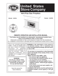
1
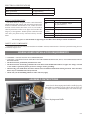
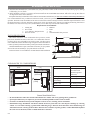
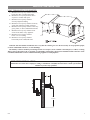
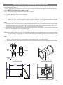
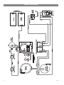
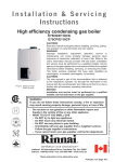
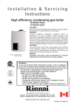
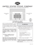
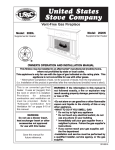
STATES ST D E OV T NI USSC E U OWNER’S OPERATION AND INSTRUCTION MANUAL COMPANY WALL MOUNTED PELLET UNIT MODEL 4840 PATENT PENDING SAFETY TESTED TO ASTM 1509-04 & ULC S-627-00 CAUTION! Read All Instructions Carefully Before Starting The Installation or Operating This Heater. Improper Installation Could Void Your Warranty! SAFETY NOTICE: If this heater is not properly installed, a house fire may result. For your safety, follow the installation instructions. Contact your local building or fire officials about obtaining a permit, restrictions and installation requirements in your area. STATES ST OV TED NI USSC E U SAVE THIS MANUAL FOR FUTURE REFERENCE THIS MANUAL WILL HELP YOU TO OBTAIN EFFICIENT, DEPENDABLE SERVICE FROM THE HEATER, AND ENABLE YOU TO ORDER REPAIR PARTS CORRECTLY. KEEP IN A SAFE PLACE FOR FUTURE REFERENCE. NOT RECOMMENDED AS PRIMARY HEAT SOURCE COMPANY UNITED STATES STOVE COMPANY 227 Industrial Park Road P.O. Box 151 South Pittsburg, TN 37380 Ussc 1 852078C SAFETY PRECAUTIONS IMPORTANT: Read this entire manual before installing and operating this product. Failure to do so may result in property damage, bodily injury, or even death. Proper installation of this heater is crucial for safe and efficient operation. Never use make-shift compromises during the installation. Before installing your heater, you must perform an initial burn in an OUTSIDE environment. Follow the Start-Up Procedure in the Operation section of this manual. This heater must be installed on an exterior wall to the outside. Contact your local building officials to obtain a permit and information on any additional installation restrictions or inspection requirements in your area. Save these instructions.. This manual has important operating and maintenance instructions that you will need at a later time. Always follow the instructions in this manual. This heater is designed and approved for premium hardwood pellet fuel only. Any other type of fuel burned in this heater will void the warranty and safety listing. Never use gasoline, gasoline-type lantern fuel, kerosene, charcoal lighter fluid, or similar flammable liquids to start or “freshen up” a fire in this heater. Keep all such liquids well away from the heater while it is in use. A working smoke detector must be installed in the same room as this product. Do not unplug the heater if you suspect a malfunction. Turn the ON/OFF SWITCH to ”OFF’ and contact your dealer. Do not operate your heater with the viewing or combustion door open. The auger will not feed pellets under these circumstances and a safety concern may arise from sparks or fumes entering the room. Never disable or bypass the safety devices in this unit. Doing so could result in damage to the unit or endanger yourself or someone else. Your heater requires periodic maintenance and cleaning (see ”MAINTENANCE ”). Failure to maintain your heater may lead to improper and/or unsafe operation. Never try to repair or replace any part of the heater unless instructions for doing so are given in this manual. All other work should be done by a trained technician. Turn the heater OFF and allow to completely cool before performing any maintenance. Disconnect the power cord before performing any maintenance! NOTE: Turning the ON/OFF Switch to ”OFF” does not disconnect all power to the electrical components of the heater. Ashes must be disposed in a metal container with a tight fitting lid. The closed container of ashes should be placed on a non-combustible surface or on the ground, well away from all combustible materials, pending final disposal. The exhaust system should be checked bi- monthly during the burning season for any build-up of flyash, soot or creosote. HOT WHILE IN OPERATION. KEEP CHILDREN CLOTHING AND FURNITURE AWAY. CONTACT MAY CAUSE SKIN BURNS. Do not touch the hot surfaces of 2 the heater. Educate all children on the dangers of a hightemperature heater. Young children should be supervised when they are in the same room as the heater. A power surge protector is required. This unit must be plugged into a 110 - 120V, 60 Hz grounded electrical outlet. Do not use an adapter plug or sever the grounding plug. Do not route the electrical cord over the heater. Do not route the cord in foot traffic areas or pinch the cord under furniture. The heater will not operate during a power outage. If a power outage does occur, check the heater for smoke spillage and open a window if any smoke spills into the room. Never block free airflow through the open vents of the unit. Keep foreign objects out of the hopper. The moving parts of this heater are propelled by high torque electric motors. Keep all body parts away from the auger while the heater is plugged into an electrical outlet. These moving parts may begin to move at any time while the heater is plugged in. Do not place clothing or other flammable items on or near this heater. WARNING—DO NOT INSTALL THIS UNIT IN A SLEEPING ROOM. CAUTION—The structural integrity of the mobile home floor, wall, and ceiling/roof must be maintained. This appliance is not intended for commercial use. DO NOT INSTALL A FLUE DAMPER IN THE EXHAUST VENTING SYSTEM OF THIS UNIT. DO NOT CONNECT THIS UNIT TO A CHIMNEY FLUE SERVING ANOTHER APPLIANCE. DO NOT USE CHEMICALS OR FLUIDS TO START THE FIRE; DO NOT BURN GARBAGE OR FLAMMABLE FLUIDS SUCH AS GASOLINE, NAPHTHA OR ENGINE OIL. DO NOT CONNECT TO OR USE IN CONJUNCTION WITH ANY AIR DISTRIBUTION DUCTWORK UNLESS SPECIFICALLY APPROVED FOR SUCH INSTALLATIONS. The chimney connector shall not pass through an attic or roof space, closet or similar concealed space, or a floor, or ceiling. Where passage through a wall, or partition of combustible construction is desired, the installation shall conform to CANICSA-B365, Installation Code for Solid-Fuel-Burning Appliances and Equipment. Ussc SPECIFICATIONS HEATING SPECIFICATIONS Heat Output1 Heating Capacity2 Fuel Burn Rate3 Burn Time (lowest setting) Hopper Capacity 16,400 BTU/hr. 500 - 1,000 sq. ft. 3/4 - 2 1/2 lbs./hr. 35 hours 28lbs BTU output will vary depending on the quality of fuel. Use PFI listed fuels for the best results. 2 Heating capacity will vary depending on floor plan layout of your home, degree of insulation, and the outside temperature. 3 Pellet size may effect the actual rate of fuel feed and burn times. Fuel feed rates may vary by as much as 20%. Use PFI listed fuel for best results. 1 DIMENSIONS Height Width Depth of Unit Depth with Mounting Wall Bracket 27” [685.7 mm] 36” [914.4 mm] 12.43” [315.77 mm] Approx. 14.27” [362.4 mm] 185 lbs Product Weight 35.87 [911] 16.92 APPROX. 1.84 [46.7] APPROX. TOP VIEW 12.43 [315.7] 36.00 [914.4] 22.50 [571.5] 4.50 [114.2] SIDE VIEW 22.25 [565.2] FRONT VIEW INTAKE/EXHAUST APPROXIMATE LOCATION DIMENSIONS Back Side Left Edge to Center Back Side Top Edge to Center Diameter of Intake\Exhaust 29.34” [745.1 mm] 10.97” [278.7 mm] 5.25” [133.35 mm] Diameter of Cut Out in Exterior Wall Refer for to Template Ussc 3 ELECTRICAL SPECIFICATIONS Electrical Rating Watts (operational) Watts (igniter running) 110-120 volt, 60Hz, 3.0Amp 175 approximately 425 approximately FUEL CONSIDERATIONS Your Pellet heater is designed to burn certified Premium Hardwood pellets that comply with Association of Pellet Fuel Industries standards. Pellets that are soft, contain excessive amounts of loose sawdust, have been, or are wet, will result in reduced performance. Failure to use proper fuel can affect the longevity of the appliance. Smaller pellets could affect feed rates. Store your pellets in a dry area and well away from the heater. Pellet Fuel Institute (PFI) Premium Standards Min. Density 40 lbs. per cubic ft. Size ¼” to 5/16” diameter, length no greater than 1½” Heat Output 8,200 BTU/lb Moisture 8% by weight or less Content Ash Content 1% by weight Salt Content 300 parts per million or less Do not use grates or other methods of supporting the fuel. Burn fuel in burnpot without modification. SAFETY AND COMPLIANCE Your Pellet heater has been safety tested and listed to ASTM E 1509-04, UM-84 and ULC S627-00, by Intertek Testing Services in Portland, Oregon, USA. MOBILE HOME INSTALLATION REQUIREMENTS WARNING! - DO NOT INSTALL IN A SLEEPING ROOM CAUTION! - THE STRUCTURAL INTEGRITY OF THE MOBILE HOME FLOOR, WALL, AND CEILING/ROOF MUST BE MAINTAINED. • The heater must be permanently attached to the wall. • The heater must be electrically grounded to the steel chassis of the mobile home with 8 GA copper wire using a serrated or star washer to penetrate paint or protective coating to ensure grounding. • When moving your mobile home, the heater must be removed while the mobile home is being relocated. After relocation, heater may be reinstalled and securely fastened. • Check with your local building officials as other codes may apply. ASSEMBLY INSTRUCTIONS Insure that the flame impingement baffle is installed properly. If the t baffle is not installed properly, push the plate up in the void at an angle, rotate it to horizontal and place it on the metal stops. Flame Impingement Baffle 4 Ussc STANDARD INSTALLATION Read this entire manual before you install and use your pellet heater. Failure to follow instructions may result in property damage, bodily injury, or even death! Before installing your heater, you must perform an initial burn in an OUTSIDE environment. Follow the Start-Up Procedure in the Operation section of this manual. Your pellet heater may be installed to code in either a conventional or mobile home (see SPECIAL MOBILE HOME REQUIREMENTS). It is recommended that only a authorized technician install your heater, preferably a National Fireplace Institute (NFI) certified specialist. This heater must be installed on an exterior wall to allow exhaust venting to meet the minimum required clearances. Once the desired location is selected, and before cutting a hole, check the outside of the structure for anything obstructing clearances to the exhaust vent. Also clear away leaves, shrubs/bushes, or trees that may be around the exhaust outlet. Required Tools for installation: 1. Venting Kit 5. Hammer 2. Power Drill 6. Knife 3. 7/32” drill bit to drill pilot holes 7. Pen 4. Wrench / Socket. 8. Noncombustible floor protector FLOOR PROTECTION This heater must have a non-combustible floor protector (ember protection) installed beneath it if the floor is of combustible material. If a floor pad is used, it should be UL listed or equal. The floor pad or non-combustible surface should be large enough to extend a minimum of 6-inches [152mm] in front and 2-inches [51mm] on each side of the heater. Canadian Installations require a minimum of 450 mm [18”] beyond the front of the unit and 200mm [8”] beyond each side of the unit A Floor Protector of 1/4 inch thick is recommended for this installation 39.87 [91012] 2 [51] 2 [51] 6 [152] Floor Protector CLEARANCES TO COMBUSTIBLES 18” [457mm] 4 J E F 8 B M M Floor Protector 6” [152mm] Combustible Floor (Allow for brace) Ceiling Back Wall 60” [1.5M] # B D L 8 B M M Left / Right Ceiling (Allow for fuel loading) Mantle / Sill Front Clearance 8 inches [203mm] Vent must meat minimum ground clearances 6 inches [152mm] 18 inches [457mm] 11 inches [279mm] 60 inches [1.5M] General Installation Notes • • • • Do not install heater where the exhaust will terminate in a window well or any opening below ground level. Special precautions may be required to prevent snow build-up within 12 inches of the air intake. Clearances around heater must provide adequate room for service, cleaning, and air circulation. Residential Garage Installation: The heater shall be located or protected so it is not subject to damage by a moving vehicle. Use care when selecting a good location within the garage. DO NOT locate the heater where the discharge air will be directed onto a nearby parked vehicle. DO NOT store containers of paint, gasoline, or other flammable liquids in the same area as the heater, inside or outside the home or structure. Ussc 5 WALL INSTALLATION • Select a wall to the exterior of the building. This wall should have the required clearance to combustibles inside and out as mentioned in this manual. Make certain that electrical wires, conduit, water or gas pipes do not pass through the area you have selected. STEP: 1 MOUNT THE WALL PLATE Note: Any material covering the wall (such as sheetrock) must not exceed 5/8” 16 mm). Option 1: Mounting on a wood-stud wall 1. Locate the studs in exterior wall. Verify the center of the stud with an edge-to-edge stud finder. Mark center point at predetermined height. 2. At the wall height you determined in the previous step, place a small nail thru center triangle hole of bracket and align the wall mount against the wall. Level bracket and verify that pilot holes are centered on studs. Use a pencil to mark the screw hole locations, and intake/ exhaust thru hole then remove the wall plate. 3. Drill pilot holes to a depth of 3” (75 mm) using a 7/32” (5.5 mm) diameter drill bit. 4. Carefully cut intake/exhaust thru hole in exterior wall thru to the outside. (SEE VENT CLEARANCES SECTION TO INSURE PROPER INSTALLATION) 5. Realign the wall mount with the pilot holes and intake/exhaust thru hole. Insert 1/4” x 2” lag bolts with washers, and tighten the lag bolts until the washers are pulled firmly against the wall mount and the wall mount is pulled firmly against the exterior wall. 5/8” [16mm] 16” [406mm] 3” [75mm] WARNING: AVOID POTENTIAL INJURIES OR PROPERTY DAMAGE! DO NOT OVERTIGHTEN THE LAG BOLTS. Option 2: Mounting on a solid concrete or concrete block wall 1. Level the wall plate and mark the hole locations. 2. At the wall height you determined in the previous step, place a small nail thru center triangle hole of bracket and align the wall mount against the wall. Level bracket and verify that pilot holes are not located in the mortar of the cinder blocks. Use a pencil to mark the pilot hole locations, and intake/exhaust thru hole then remove the wall plate. 3. Drill pilot holes to a depth of 3” (75 mm) using a 1/2 in. (12.7 mm) diameter masonry drill bit. 4. Carefully cut intake/exhaust thru hole in exterior wall thru to the outside. (SEE VENT CLEARANCES SECTION TO INSURE PROPER INSTALLATION) 5. Insert 1/4” concrete wall anchors into the pilot holes and make sure that the anchors are seated flush with the concrete surface. 6. Align the wall plate with the anchors. Place washers over the screw holes in the wall plate, insert 1/4” x 2” lag bolts through the washers, and then tighten the lag bolts until the washers are pulled firmly against the wall plate and the wall mount is pulled firmly against the exterior wall. STEP: 2 MOUNTING THE HEATING UNIT TO THE WALL PLATE Note: The Heating Unit is heavy. You will need assistance with this step. 1. After mounting Wall Plate to wall. Cut hole 2. Align intake/exhaust with hole in wall and carefully insert heating unit. Tilt top towards the wall and lower the Heating Unit onto the wall plate making sure that the hooks on the top of the left and right brackets slide over the top of the wall plate. Allow the Heating Unit to pivot parallel to the wall plate and lift to allow lower hooks to engage on the bottom of the Wall Mount. 3. Insert locking brackets into the lower slots of Heating Unit back mounting brackets. Tighten ¼-20 hex head bolts to lock Heating unit onto Wall Plate. 6 Ussc VENTING -INSTALLATION VENT TERMINATION CLEARANCES: A. Minimum 4-foot [1.2m] clearance below or beside any door or window that opens. B. Minimum 1-foot [0.3m]clearance above any door or window that opens. C. Minimum 2-foot [0.6m] clearance from any adjacent building. D. Minimum 7-foot [2.1m] clearance from any grade when adjacent to public walkways. E. Minimum 2-foot [0.6m] clearance above any grass, plants, or other combustible materials. F. Minimum 4-foot [1.2m] clearance from an forced air intake of any appliance. G. Minimum 2-foot [0.6m] clearance below eves or overhang. H. Minimum 1-foot [0.3m] clearance horizontally from combustible wall. NOTICE: This unit shall be installed in such a way that the exhaust gases are directed so they do not jeopardize people, overheat combustible structures, or enter buildings. The chimney connector shall not pass through an attic or roof space, closet or similar concealed space, or a floor, or ceiling. Where passage through a wall, or partition of combustible construction is desired, the installation shall conform to CAN/ CSA-B365, Installation Code for Solid-Fuel-Burning Appliances and Equipment. IMPROPER INSTALLATION: The manufacturer will not be held responsible for damage caused by the malfunction of a heater due to improper venting or installation. Call (800) 750-2723 and/or consult a professional installer if you have any questions. 6” (152 mm) 24” (609mm) Ussc 7 VENT INSTALLATION/ASSEMBLY PROCEDURE A source of fresh air shall be provided when required. To ensure this make sure that the intake to the concentric vent system is clear of all obstructions during use. You must use the Duravent FasNSeal Concentric Vent System designed to work with this appliance from United States Stove Company. DO NOT substitute other venting systems. The 3” x 5” horizontal square termination kit (35CVS-KUS) includes: 1. 3” x 5” stove adapter 2. Adjustable Horizontal Square Cap 35CVS-HZSQ 3. Wall Thimble 35CVS-WT Step 1) DirectVent Pro pipe and fittings are designed with special twistlock connections. To connect the venting system to the appliance flue outlet, a twist-lock Appliance Adaptor is required. The adaptor will be supplied for installation in the field. Assemble the desired combination of Pipe Sections and Elbows to the Appliance Adaptor. Notes: 1. Twist-lock procedure: Line up locking lugs on male and female ends of pipe sections. Insert the male end of pipe into the female end until the locking lugs are covered. Twist the female end clockwise an eighth of a turn to lock sections together. Three screws are required to secure the joint, ensure they do not penetrate the inner wall of the vent pipe. 2. Horizontal runs of vent pipe must be supported to prevent any downward sags. Horizontal pipe sections should be supported at least every 4-feet. Wall Straps can be used for this purpose. 3. Seal all joints with high temperature silicone. Step 2) With the appliance adaptor and pipe section attached to the appliance, slide the appliance into its correct location, and mark the wall for a hole of the appropriate size. The center line of the pipe should line up with the center of the hole. Cut and frame the hole in the exterior wall where the vent will be terminated. A Wall Thimble is required. Notes: 1. The horizontal run of venting must be level, or have a 1/4-inch rise for every 1-foot of run towards the termination. Never allow the vent to run downward. A downward slope can trap heat and become a possible fire hazard. 2. The location of the Horizontal Vent Termination on an exterior wall must meet all local and national building codes, and must not be easily blocked or obstructed. Termination clearances as shown in the VENT TERMINATION CLEARANCES section. MALE END SCREWS FEMALE END Duravent Fasnseal Concentric Vent System Twistlock Procedure Exterior Wall Thimble Adjustable Horizontal Square Cap 8 Concentric Vent Attachment Ussc UNDERSTANDING YOUR HEATER HOW YOUR HEATER WORKS Your pellet heater operates on a timer based auger fuel feed system, that is controlled by a digital circuit board. The fuel is delivered from the auger into a burn pot, which is the vessel where the combustion process takes place. Based upon the heat ranges (1-5), the heater will feed the appropriate amount of fuel to reach a set temperature range. Note that the amount of heat produced by the heater is proportional to the rate of the fuel that is burned. Your heater is equipped with an automatic ignition system that should ignite the fuel within 5-10 minutes from pressing the ON button. As pellets fall into the burn pot and ignite, outside air is drawn in to feed the fire by a combustion blower. The post combustion gases are then pulled through the heat exchanger as they are traveling out the exhaust. As the heater warms up, room air is circulated around the heat exchanger by means of a room air blower, distributing warm air into the room. Because a forced draft pressure is required for the combustion process inside your heater, it is extremely important that the exhaust system be properly maintained. And, that when operating your heater, you make sure that the viewing and combustion doors are properly closed and/or sealed. CONTROL PANEL OVERVIEW Turning the heater ON/OFF, as well as adjustments for the fuel feed rate is performed by pressing the appropriate button(s) on the control panel which is located on the front, lower left-hand corner of your heater. ON/OFF • • Pressing the “ON” button on the control panel will begin the start-up sequence for the heater. Fuel will begin to feed through the auger feed system then ignite after approx. 5 minutes. Pressing the “OFF” button on the control panel will cause the heater to enter its shut-down sequence. The fuel feed system will stop pulling fuel from the hopper and, once the fire goes out and the heater cools down, the fans will stop running. HEAT RANGE • • • Pressing the “Heat Range” arrows, up or down, will adjust the amount of fuel being delivered to the burn pot. The exhaust blower will start. Note that this appliance pulses the exhaust blower in order to achieve the proper air to fuel ratio, and to also aid in the cleaning of the burn pot. Once the heater reaches a set temperature, the room fan will come on. LIGHT (LED) INDICATORS • • • • • • Ussc Heat Range LED - displays the selected heat setting. Number “1” LED lights to display that there is power to unit even if the heater is off. Door Sw LED - lights when front viewing door is opened or if the hopper lid is raised. Press Sw LED - lights if pressure is lost inside the combustion chamber. (See “Errors”) E LED - Operational Error (See “Errors”) ON LED - Flashes in start-up mode. On solid during Run mode OFF LED - Flashes during shut down mode 9 OPERATION UNIT PREPARATION After properly installing your heater, you will need to attach the electrical cord to the right side blower housing first; then plug it into a 110-volt outlet (an outlet surge protector is highly recommended). PERFORMING AN INITIAL BURN You must perform an initial burn in this appliance before installing it in your home or garage. This process is to ensure that the appliances is functioning correctly, to cure the high temperature paint and burn off any oil that is present in the sheetmetal components of the combustion chamber. For the initial burn, only add a small amount of fuel, approximately 4-5 lbs. or about the amount to fill a 2 lb. coffee can. Operate the appliance on the 3 or 4 heat setting for approximately 30 minutes to an hour. There will probably be a small amount of smoke or fumes irradiating from the appliance during this process. Follow the Start-Up procedure below to begin your burn. START-UP PROCEDURE Never use gasoline, gasoline-type lantern fuel, kerosene, charcoal lighter fluid, or similar liquids to start or “freshen up” a fire in this heater. Keep all such liquids well away from the heater while it is in use. 1. Verify that the hopper is clean and free of foreign matter. 2. Fill the hopper with wood pellets; do not allow any part of the bag or any other foreign material into the hopper, as this may jam the auger. 3. Ensure that all pellet matter is cleared from the hopper seating surface. 4. Close the hopper lid. The unit WILL NOT feed fuel with the hopper lid open. 5. Verify that there is no pellet fuel, ash, or foreign matter in the burn-pot before starting the appliance. 6. Make sure that the viewing door and combustion door is securely closed (the safety switch will not allow the heater to feed fuel if they are left open. 7. Press the “ON” button on the control pad and set the “heat RANGE” to your desired setting. The ON light will be flashing and the light corresponding with the heat setting will be light. What will happen next.... The heater will begin to feed fuel and the exhaust (draft) blower is running. Note that the exhaust blower is pulsing. The auto-start ignitor will ignite the fuel in approximately 5-10 minutes. In the start-up mode, the “ON” LED will flash until it reaches a factory preset temperature. At that point, the “ON” LED will come on solid and the heater will begin to ramp up to your selected heat range. The Room Air Blower will not function until the heater reaches a factory preset temperature. SHUT DOWN PROCEDURE Press the “OFF” button on the control pad to put the stove in shut down mode. At this time, the red light above the OFF will blink and the “ON” light will go off. The auger will stop feeding pellets, but the distribution blower and exhaust blower will continue to operate. When the internal temperature of the unit drops below the factory preset temperature, the distribution blower and exhaust blower will cease to operate. The red light will then shut off and the unit will be completely shut down. The hotter the unit is during its operation, the longer it will take for the stove to complete the shut down cycle. If the stove stays on for more than 1 hour after pressing the “OFF” button and you are sure that the fire is out, the stove can be unplugged from the outlet. After approximately 10 seconds, the unit can be re-connected to the power source and the control board will be reset. WARNING: NEVER SHUT DOWN THIS UNIT BY UNPLUGGING IT FROM THE POWER SOURCE. 10 Ussc OPERATION DAILY OPERATION • Never place your hand near the auger while the heater is in operation. • This unit should be filled when the hopper level drops below 3-inches. • In the event of a power outage, the heater will not function. If the unit was “ON” when the power outage occurred, one of the following will take place: 1. If the heater is still warm, it will resume feeding fuel and continue to operate normally. If the fire has gone out, you will have to press the “OFF” button and then the “ON” button again to begin a new start-up sequence. 2. If the heater has cooled-off, it will reset to its “OFF” condition. At this point, you may press the “ON” button and the unit will begin a new start-up sequence. Make it a habit to empty the burn pot in these situations. NOTE: The unit will also shut down in the event of an exhaust blower failure; if this is the case, the unit will not re-start and you must contact Customer Service at (800) 750-2723. SAFETY AND CONVENIENCE FEATURES Your heater incorporates safety switches that helps ensure that everything is in proper working order before feeding fuel to the burn pot. The heater will not operate if the viewing or combustion door is left open; or if the exhaust blower fails or the exhaust system is blocked. The RTD, Resistance Temperature Device, will prevent your heater from operating at abnormally high temperatures. The heater has two over temperature limits. If the unit reaches the first limit, it will reduce fuel consumption in order to reduce temperatures. If the unit reaches the second limit, it will shut down and will need to be restarted. Your heater also includes an auto-start igniter as a standard feature. The use of other fire starter materials (wood chips, starter gel, etc.) is not necessary. By simply pressing the “ON” button on the digital control panel, your heater will begin to feed fuel and automatically start within 5 minutes. MAINTENANCE Failure to clean and maintain this unit as indicated can result in poor performance, safety hazards and void your warranty. Unplug your heater’s electrical cord prior to removing the back panel or opening the exhaust system for any inspection, cleaning, or maintenance work. Never perform any inspections, cleaning, or maintenance on a hot heater. Do not operate heater with broken glass , leakage of flue gas may result. EXHAUST SYSTEM The by products of combustion contain small particles of fly ash. Fly ash will collect in the exhaust venting system and restrict the flow of flue gases. Incomplete combustion, such as during startup, shutdown, or incorrect operation of the heater will lead to soot or creosote formation which will collect in the exhaust system and if ignited, an extremely hot fire could result. Therefore, it is important that the exhaust system be inspected and cleaned at least bi-monthly during the burning season. Contact your local municipal or provincial fire authority for information on how to handle a fire. Have a clearly understood plan to handle a fire if one should ever occur. Cleaning or monitoring the areas behind the front cleanout door should be done frequently to ensure minimum fly ash or soot/creosote build-up. INTERIOR CHAMBERS Periodically remove and clean the burn pot, flame impingement plate and the areas behind the cleanout door. In particular, it is advisable to clean out the holes in the burn pot to remove any build up that may prevent air from moving through the burn pot freely. As good practice, you should remove and clean the burn pot each time you restart the heater, weekly or as needed as this ensures that the best efficiency is achieved. If a vacuum is used to clean your heater, we suggest using a vacuum designed for ash removal. Some regular vacuum cleaner (i.e. shop vacs) may leak ash into the room. Ussc 11 MAINTENANCE ASH DISPOSAL Ashes should be placed in a metal container with a tight fitting lid. The closed container of ashes should be placed on a noncombustible floor or on the ground, well away from all combustible materials, pending final disposal. If the ashes are disposed of by burial in soil or otherwise locally dispersed, they should be retained in the closed container until all cinders have been thoroughly cooled. Do not place other waste in the same container. CHECK AND CLEAN THE HOPPER Check the hopper periodically to determine if there is any sawdust or pellets that are sticking to the hopper surface. Clean as needed. DOOR AND GLASS GASKETS Inspect the door’s and ash pan’s gaskets periodically. These may need to be removed to have frayed, broken, or compacted gaskets replaced. Keep door, glass, and ash pan seals in good condition. BLOWER MOTORS Clean the air holes on the motors of both the exhaust and distribution blowers annually. Remove the exhaust blower from the exhaust duct and clean out the internal fan blades as part of your fall start-up. PAINTED SURFACES Painted surfaces may be wiped down with a damp cloth. If scratches appear, or you wish to renew your paint, contact your Authorized pellet heater Dealer to obtain a can of suitable high-temperature paint. GLASS Cleaning - We recommend using a high quality glass cleaner. Should a build up of creosote or carbon accumulate, you may wish to use 000 steel wool and water to clean the glass. DO NOT use abrasive cleaners. DO NOT perform the cleaning while the glass is HOT. , In the event you need to replace the glass, follow these instructions. Wear leather gloves or any other gloves suitable for handling broken glass. Dispose of all broken glass properly. Use ONLY high temperature ceramic glass of the correct size and thickness. DO NOT substitute alternative materials for the glass. Contact your authorized dealer to obtain this glass. The firebox glass is replaced as follows: remove the retainers and any broken glass or gasketing from the sealing face of the door. Install a new glass gasket. Re-install the retainers to hold the glass. Be careful not to overtighten the screws for this could damage the glass. To replace the viewing door glass remove the back of the door and the insulation, then proceed as described for the firebox door glass replacement. DO NOT abuse the door glass by striking, slamming or similar trauma. Do not operate the stove with the glass removed, cracked or broken. FALL START UP Prior to starting the first fire of the heating season, check the outside area around the exhaust and air intake systems for obstructions including leaves, bushes/shrubs, and/or trees. Clean and remove any fly ash from the exhaust venting system. Clean any screens on the exhaust system and on the outside air intake pipe. Turn all of the controls on and make sure that they are working properly. This is also a good time to give the entire heater a good cleaning throughout. SPRING SHUTDOWN After the last burn in the spring, remove any remaining pellets from the hopper and the auger feed system. Scoop out the pellets and then run the auger until the hopper is empty and pellets stop flowing. Vacuum out the hopper. Thoroughly clean the burn pot, and firebox. The exhaust system should be thoroughly cleaned. If removing the unit for storage, store the heater in a dry location. YEARLY SERVICING A yearly servicing and cleaning by your Authorized pellet heater dealer is recommended. A fee may be charged for this service. 12 Ussc TROUBLE SHOOTING ERRORS Disconnect the power cord before performing any maintenance! NOTE: Switching the appliance to ”OFF” does not disconnect all power to the electrical components of the heater. Never try to repair or replace any part of the heater unless instructions for doing so are given in this manual or supplied from the factory. All other work should be done by a trained technician. PROBLEM Orange, lazy flame, excessive fuel build-up in the burn pot CAUSE: To rich air/fuel mixture • Clean out the burn pot and behind the cleanout door. • Make sure that the combustion door is closed and sealed properly. If not, adjust door catch and/or replace door gaskets. • Check that the exhaust is clear of any obstructions. Clean as needed • Check for proper seating of the burn pot. PROBLEM Fire goes out or heater shuts down. CAUSE: Burn pot burns out of fuel • Hopper is empty, refill the hopper. • Loss of draft pressure. Make sure that the combustion door is closed and sealed properly. If not, adjust door catch and/or replace door gaskets. Check that the exhaust is clear of any obstructions. Clean as needed. • Make sure the viewing door and hopper lid is closed completely. • Auger system is jammed or there is a “bridging” of the fuel in the hopper, preventing fuel from flowing into the auger feed system. PROBLEM Heater does not start a fire when the “ON” button is pushed CAUSE: Auto-Start Igniter fails to ignite the fuel in the burn pot. • Turn the heater “OFF”. Clear the unburnt fuel from the burn pot and try again. • Check the pellet quality. Replace if moist, wet, or dirty. • Loss of draft pressure. Make sure that the combustion door is closed and sealed properly. If not, adjust door catch and/or replace door gaskets. Check that the exhaust is clear of any obstructions. Clean as needed. • Check that the auto-start igniter is not blocked with ash or soot. (The igniter is located behind the burn pot on the back wall of the combustion chamber.) • The auto-start igniter gets “red hot” during start-up. If you can not visibly see the igniter glowing during start-up, then the igniter may need to be replaced or there is a problem with the electrical control system. • Check for proper alignment between the burn pot and the igniter tube. PROBLEM Heater enters shut-down mode CAUSE: Heater has reached the 2nd over temperature limit. • To much fuel in the burn pot. Restart heater after heater has cooled. • RTD sensor in the room discharge air may be faulty causing the room fan not to come on. Contact your dealer. Ussc 13 14 48 46 42 49 50 47 55 58 54 52 56 41 53 57 56 60 51 24 12 8 13 1 14 39 59 15 40 28 16 10 26 9 11 4 7 25 32 27 29 5 20 2 6 22 3 31 61 21 23 17 63 19 66 18 62 64 65 34 35 IN ORDER TO MAINTAIN WARRANTY, COMPONENTS MUST BE REPLACED USING ORIGINAL MANUFACTURERS PARTS PURCHASED THROUGH YOUR DEALER OR DIRECTLY FROM THE APPLIANCE MANUFACTURER. USE OF THIRD PARTY COMPONENTS WILL VOID THE WARRANTY. 45 44 43 36 33 30 38 PARTS DIAGRAM Ussc Part No. 69800 26195 26196 80531 892004 88180 26231 891748 80619 88118 69820 69819 26175 89586 88184 88118 83529 891169 80529 891132 83534 26202 26237 88183 69814 26204 80542 26205 26210 26200 88178 88179 891148 26217 80462 26229 69811 69808 Item 1 2 3 4 5 6 7 8 9 10 11 12 13 14 15 16 17 18 19 20 21 22 23 24 25 26 27 28 29 30 31 32 33 34 35 36 37 38 Title Burn Chamber Enclosure Assembly IGNITOR COVER FEED TUBE COVER RTD, PLATINUM MAGNET INSULATION, RIGHT SDE- CHAMBER RTD MOUNTING BRACKET BURNPOT WELDMENT IGNITOR CARTRIDGE GASKET, IGNITOR FLANGE IGNITOR TUBE Burn Chamber Door CLEAN DOOR, BURN CHAMBER AUGER NIPPLE GASKET CLEAN DOOR, BURN CHAMBER GASKET, IGNITOR FLANGE HAIRPIN HOSE, HEATER AUGER MOTOR AGITATOR BUSHING RETAINING RING AUGER RETAINING BRACKET, AUGER BUSHING GASKET - EXHAUST BLOWER DOOR SWITCH ASSEMBLY ENCLOSURE, DISTRIBUTION FAN 3" DOUBLE CENTRIFUGAL BLOWER - 125CFM ENCLOSURE PANEL, DISTRIBUTION FAN EXTENERS, ROOM FANS PANEL, MAIN CABINET TOP AND SIDE INSULATION, WRAPPED- CHAMBER INSULATION, LEFT SIDE - CHAMBER HANDLE, PLASTIC LID, HOPPER RECEPTACLE, 3 PRONG COVER, AUGER ACCESS Door Switch Assembly Wall Mount Bracket Assembly Ussc 1 2 1 1 1 1 1 1 1 1 1 Qty. 1 1 2 1 1 1 1 1 1 1 1 1 1 1 1 1 1 2 1 1 1 1 1 1 1 1 1 26187 891121 69809 26211 80545 80549 26360 892208 60 61 63 64 65 66 62 51 52 53 54 55 56 57 58 59 Part No. 80573 88182 69804 26208 26199 88181 26218 69818 892174 26216 892215 88087 (4880) 69803 26209 26214 80555 69812 89390A 26230 80550 26185 Item 39 40 41 42 43 44 45 46 47 48 49 50 Left Door Assembly FRONT DOOR, RIGHT BACK PANEL, LEFT DOOR PWA, DISPLAY BOARD ASSEMBLY, FRAME 01 RUBBER GROMMET (3/8 ID) PC BOARD COVER PLATE ASSY, KEYPAD EXHAUST PANEL, TOP, BOTTOM, AND BACK SIDE EXHAUST PANEL, RIGHT SIDE VACCUM HOSE Contol Board Assembly BRACKET, PRESSURE SWITCH/ PC BOARD MOUNTING ASSY, CONTROLLER BOARD PRESSURE SWITCH EXHAUST/INTAKE BEAUTYRING DURAVENT DIRECT VENT (35CVS-AD) Title BLOWER, EXHAUST - 70 CFM MAIN GASKET - EXHAUST BLOWER Right Door Assembly LEFT FRONT DOOR, MAIN BACK PANEL, MAIN DOOR INSULATION, LEFT FRONT DOOR DOOR SPACER WELDMENT, EXHAUST LOUVER DOOR PLUNGER FRAME, VIEWING WINDOW DOOR VIEWING GLASS GASKET, WINDOW, .125 X 1 W/PSA 1 1 1 1 1 1 1 1 1 1 1 1 1 1 1 1 1 Qty. 1 1 1 1 1 1 2 1 1 1 1 1 PARTS LIST 15 WIRING DIAGRAM 16 Ussc HOW TO ORDER REPAIR PARTS This manual will help you obtain efficient, dependable service from your Pellet heater, and enable you to order repair parts correctly. Keep this manual in a safe place for future reference. When writing, always give the full model number which is on the nameplate attached to the heater. 1. The part number 2. The part description 3. The model number: 4. The serial number:____________________ STATES ST OV TED I N USSC COMPANY Ussc E U When ordering repair parts, always give the following information as shown in this list: 4840 UNITED STATES STOVE COMPANY 227 Industrial Park Road P.O. Box 151 South Pittsburg, TN 37380 (800) 750-2723 WWW.USSTOVE.COM 17 NOTES 18 Ussc PLEASE SEAL WITH CLEAR TAPE BEFORE MAILING Warranty Registration Form Please take a moment and properly register your new stove within 10 days of purchase by completing this form. You can also complete this form by visiting us at usstove.com Owner: ____________________________________________________________________ Address:__________________________________________________________________ City:____________________________ State: __________ Zip:______________________ Email Address: ______________________________________________________________ Phone: ____________________________________________________________________ Dealer/Store:________________________________________________________________ City:____________________________ State: __________ Zip:______________________ Stove Model: ________________________________________________________________ Serial Number:______________________________________________________________ Date Purchased: ____________________________________________________________ Date Installed: ______________________________________________________________ PLEASE COMPLETE THE SURVEY BELOW: How do you currently heat your home? Electric Natural Gas Propane Heating Oil How did you hear about United States Stove Company? Internet Local Store Dealer Friends/Relatives Wood Pellet Trade Show Other: ________________________________________________________________ What were your reasons for selecting one of our products? (check all that apply) Convenience Salesperson Appearance Price Heating Bill Savings Performance Add On Quality Where is your hearth appliance installed? Living Room Family Room Den/Office Bedroom Outdoor Kitchen Bath Masonry Fireplace Sun Room Were you satisfied with the service of the dealer/store? YES NO Did you find the unit you were looking for? YES NO May we contact you regarding your dealer, your purchase or your unit? YES NO Please rate your dealer/store on the following: Product Knowledge Excellent General Attitude Excellent Overall Service Excellent Ussc Good Good Good Fair Fair Fair Poor Poor Poor 19 ______________________ PLACE STAMP HERE ______________________ ______________________ United States Stove Company 227 Industrial Park Road South Pittsburg, TN 37380 Attn: Registration Form PLEASE SEAL WITH CLEAR TAPE BEFORE MAILING 20 851997 Ussc