1
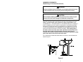
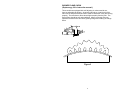
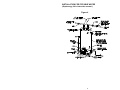
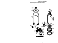
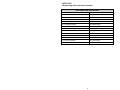
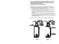
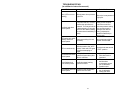
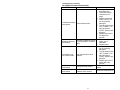
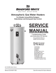
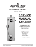
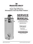
SUPPLEMENT TO INSTRUCTION MANUAL P/N 238-44219-00 (Replaces pg. 2 in instruction manual.) CONGRATULATIONS! You have just purchased one of the finest water heaters on the market today! This installation, operation and instruction manual will explain in detail the installation and maintenance of your new Flammable Vapor Ignition Resistant Gas Water Heater. We strongly recommend that you contact a plumbing professional for the installation of this water heater. We require that you carefully read this manual, as well as the enclosed warranty, and refer to it when questions arise. If you have any specific questions concerning your warranty, please consult the plumbing professional from whom your water heater was purchased. For your records we recommend that you write the model, serial number and installation date of your water heater in the maintenance section in the back of this manual. This manual should be kept with the water heater. Special Flammable Vapor Ignition Resistant System: This water heater is equipped with a Flammable Vapor Ignition Resistant System. In the event of improper usage or storage of gasoline or other flammable materials in the location where the water heater is installed, the technology will resist ignition of the flammable vapors outside the confines of the water heater. The Flammable Vapor Ignition Resistant System features: Advanced Flame Arrestor Design. Intelligent Diagnostic Control to prevent burner/pilot operation with restricted airflow. Spark Igniter Sight Window to observe operation of pilot and burner. FOR YOUR SAFETY: Activation of the Flammable Vapor Ignition Resistant System occurs when flammable vapors are drawn into the water heater and are combusted. If flammable vapors are detected: Do not try to light any appliance. Do not touch any electrical switch; Do not use any phone in your building. Leave the premises and immediately call the fire department from a neighbor’s phone. Follow the fire department’s instructions. Once the flammable vapor has been evacuated, contact your plumbing professional or the manufacturer for further instructions. Replacement of a Flammable Vapor Ignition Resistant System equipped water heater due to a flammable vapor shutdown is not covered under the terms of the limited warranty. 238-46789-00F 6/10 MINIMUM CLEARANCES (Replaces pg. 9 in instruction manual.) WARNING Failure to adhere to these installation and operating instructions may create a hazard to life and property and will nullify the warranty. CAUTION Do not solder plumbing joints directly above the flue. Solder may fall down the flue and cause damage to combustion components. This installation shall allow access to the front of the water heater and adequate clearance shall be provided for servicing and operating this water heater. The water heater may be installed on either a combustible or noncombustible floor. If the water heater is to be installed directly on carpeting, it shall be installed on top of a metal or wood panel (or equivalent) extending beyond the full width and depth of the appliance by at least three (3) inches (7.6 cm) in any direction or, if the appliance is to be installed in an alcove or closet, the entire floor shall be covered by the panel. If the rating plate or the label on the front of the water heater specifies minimum clearances less than those listed in the below table, the water heater may be installed in accordance with the minimum clearances listed on the rating plate or the label on the front of the water heater. If it is necessary to install this water heater in an alcove, use the clearances listed in Figure 1. Figure 1 2 Lighting and Shutdown Instructions (Replaces pg. 18 in instruction manual.) LEFT INNER DOOR SIGHT GLASS RIGHT INNER DOOR ELECTRODE THERMOPILE 3 PILOT BURNER THERMOSTAT ADJUSTMENT (Replaces pg. 19 in instruction manual.) status 160°F and 180°F control Figure 2 The gas control knob is set to the “OFF” position when shipped from the factory. Remember that lower temperature settings are more energy efficient. Adjust the temperature by turning the gas control knob. It is suggested that the starting point setting not exceed approximately 120°F (48.9°C) or “Hot” setting on the thermostat. DANGER Hotter water increases the risk of scald injury. Scalding may occur within five (5) seconds at a temperature setting of 140F (60C). To protect against hot water injury, install an ASSE approved mixing valve in the water system. This valve will reduce point of discharge temperature by mixing cold and hot water in branch water lines. A licensed plumbing professional or local plumbing authority should be consulted. Note: This water heater is equipped with an energy cut out device to prevent overheating. Should overheating occur or the gas supply fail to shut off, turn off the manual gas control valve to the appliance and call a qualified service technician. Note: Whenever the water heater is filled with cold water, condensate will form on the cool tank surface and drops of water will fall on the hot burner and combustion chamber surfaces producing a “sizzling” noise. Condensation is normal and does not indicate a leak. It will disappear when the tank becomes heated. 4 BURNER FLAME CHECK (Replaces pg. 20 in instruction manual.) These models are equipped with self adjusting air mixture and do not have an adjustable air shutter. At periodic intervals, a visual check of the main burner and pilot flames should be made to determine if they are burning properly. The main burner flame should light smoothly from the pilot. The burner flame should be soft and undefined. After five minutes of burner operation the burner face should be glowing orange and emitting an orange flame. Figure 3 5 INSTALLATION FOR POTABLE WATER (Replaces pg. 24 in instruction manual.) Figure 4 6 PARTS LIST DRAWING (Replaces pg. 25 in instruction manual.) 7 PARTS LIST (Replaces pg. 26 in instruction manual.) PART NAME AND DESCRIPTION 1. Draft Diverter 14a. Resistance Temperature Detector 2. Jacket Head Pan 15. Drain Valve 3. Jacket 16. Gas Valve 4. Outer Door 17. Thermal Well 5. Magnesium Anode–Hot Water Outlet 18. Wire Harness 6. Flue Baffle Assembly 19. Radiant Burner 7. Dip Tube–Cold Water Inlet 20. Orifice 8. Temperature and Pressure Relief Valve 21. Manifold Mount 9. Glass Lined Tank 21a. High Temperature Limit Switch 10. Secondary-Air Restrictor Plate 22. Gas Feedline to Burner 11. Combustion Chamber Assembly 23. Gas Feedline to Pilot 12. Jacket Base Pan 24. Spark Igniter 13. Inner Door Gasket 25. Thermocouple 14. Inner Door Assembly 26. Pilot Assembly 8 THE FOLLOWING INSTRUCTIONS ARE FOR INSTALLATION OF: GAS WATER HEATERS SUITABLE FOR WATER (POTABLE) HEATING AND SPACE HEATING (Replaces pg. 27 in instruction manual.) All piping components connected to this water heater for space heating applications must be suitable for use with potable water. In Massachusetts, space heating piping length must not exceed 50 feet. 1. Toxic chemicals, such as those used for boiler treatment, must not be introduced into potable water used for space heating. 2. This water heater must not be connected to an existing heating system or component(s) previously used with a non-potable water heating appliance. 3. When the system requires water for space heating at temperatures higher than required for other means, such as an ASSE approved mixing valve must be installed to temper the water for those uses in order to reduce the scald hazard potential. Please refer to figure 5 and figure 6 for suggested piping arrangements. Figure 5 Figure 6 9 TROUBLESHOOTING (In addition to instruction manual.) LED Status Control Status None (LED not on or flashing) Millivolt power is not present. Light Pilot One flash and three second pause. If set point knob is in "PILOT" position then pilot flame is detected. Turn set point knob to desired setting. If set point knob is at the desired setting the thermostat is satisfied (no faults). LED strobe (two quick Thermostat calling for heat flashes) and three (no faults). second pause. Set point knob has been recently turned to the "OFF" LED on continuously. position. Wait until LED goes out before attempting to relight. Weak pilot flame detected. Two flashes and three System will reset when pilot second pause. flame is sufficient. Three flashes and three second pause. Insufficient water heating. System will reset. Four flashes and three Excessive tank temperature. second pause. System must be reset. 10 Probable Cause Gas valve is not powered. Light pilot. Gas valve is powered and waiting for the set point knob to be turned to a water temperature setting. If the set point knob is already at the desired setting, temperature demand is satisfied (no call for heat). Tank temperature below setpoint of thermostat. Set point knob was turned to "OFF" position. 1. Unstable pilot. 2. Pilot tube block or restricted. 1. Thermowell sensor and chamber temperature sensor out of calibration. 2. Possible short. 1. Thermowell sensor out of calibration. 2. Faulty gas valve. Troubleshooting continued- (In addition to instruction manual.) LED Status Control Status Probable Cause 1. Damage to the thermowell wire. 2. Thermowell sensor resistance out of range. 3. Replace thermowell. 4. Verify control is not wet or physically Five flashes and three Thermostat well fault. damaged. second pause. 5. Turn set point knob to "OFF" position. Turn set point knob to "PILOT" position and light pilot. 6. Replace gas valve if five flash error persists. 1. Chamber temperature Chamber temperature sensor sensor out of Six flashes and three out of specification. Possible calibration. second pause. short. 2. Possible short. 1. Verify control is not wet or physically damaged. 2. Turn set point knob to "OFF" position. Turn Seven flashes and Gas valve electronic fault set point knob to three second pause. detected. "PILOT" position and light pilot. 3. Replace gas valve if seven flash error persists. Eight flashes and three Pilot valve stuck in open False pilot flame present. second pause. position. Ten flashes and three Insufficient combustion air Insufficient combustion air. second pause. detected. Reset system. 11 Notes 12