1
1
Focke Wulf Fw 190 A
- The late Variants –
Aircraft Expansion for Microsoft Flight Simulator X
User Manual
November 2009, Version 1.0
2
A production of
Mathias Pommerien
Fichtenhof 13
29525 Uelzen
Germany
support @classics-hangar.de
http://www.classics- hangar.de
System Requirements:
Windows XP SP 2 , Windows Vista or Windows 7,
Microsoft Flight Simulator X @ Service Pack 2, Gold or Acceleration Expansion Pack,
Dual Core Processor @ 2.4 GHz or better
512 MB DX9 Graphics Card
300 MB free disc space for the executable, 900 MB free disc space for the installation.
Copyright 2009 Classics Hangar Mathias Pommerien, Fichtenhof 13, 29525 Uelzen, unless
stated otherwise. All rights reserved. Sound module licensed to Classics Hangar by Bill
Leaming.
No re-use/re hosting/redistribution of any part of this work is permitted without prior
written permission by Mathias Pommerien. Microsoft Windows 2000, Windows, XP, Vista,
Windows 7 and Flight Simulator are either registered trademarks or trademarks of
Microsoft Corporation in the USA or other countries.
3
Table Of Content
Page
Introduction.......................................................................................................................
Features...........................................................................................................................
Installation........................................................................................................................
Texture Configuration
Exterior Textures...................................................................................................
Interior Textures, Texture Manager....................................................................
First Run, Security Warning...........................................................................................
Notes for Repainters, Paint Kit......................................................................................
Development History
Fw 190 A-5...............................................................................................................
Fw 190 A-6...............................................................................................................
Fw 190 A-7...............................................................................................................
Fw 190 A-7/R2.........................................................................................................
Fw 190 A-8...............................................................................................................
Fw 190 A-8/R2 'Sturmjäger'..................................................................................
Fw 190 A-9...............................................................................................................
Fw 190 Today, the Flugwerk Fw 190 A-8/N (not included to this package)
The Cockpit.......................................................................................................................
Operating the FS Aircraft, general notes......................................................................
Flying at Night..................................................................................................................
Cockpit Overview
Forward Panel Fw 190 A-5 to A-7.........................................................................
Left Console Fw 190 A-5, A-6................................................................................
Right Console Fw 190 A-5 to A-7.........................................................................
Details forward and rear electrical Panel Fw 190 A-5 to A-7............................
Left Console Fw 190 A-7........................................................................................
Forward Panel Fw 190 A-8, A-9............................................................................
Left and right Console Fw 190 A-8, A-9...............................................................
Details forward and rear electrical Panel Fw 190 A-8, A-9...............................
Specific Operation Procedures
Fuel Management...................................................................................................
Gear Operation........................................................................................................
Flaps Operation, Trimming....................................................................................
Radio Operation Fw 190 A-5 to A-7.......................................................................
Radio Operation Fw 190 A-8, A-9..........................................................................
Manual RPM Adjustment, Prop Feathering.........................................................
Canopy and Canopy Emergency Release............................................................
Main Flight and Engine Instruments, description inclusive unit conversion tables
and operational limits.....................................................................................................
Changing or removing Payloads, dropping bombs.....................................................
Credits...............................................................................................................................
5
5
6
4
6
7
8
8
9
10
12
13
14
16
18
18
19
19
20
20
21
21
22
23
23
24
25
26
27
28
29
31
33
33
34
39
43
Introduction
With this second instalment in the Classics Hangar Fw 190 series the virtual pilot can now
make the transition to blind flying and early radio navigation. Experience the sleek
manoeuvrability of the Fw 190 A-5, make your way over the improved A-6 and A-7 sub
variants to the versatile A-8. Deal with the weight of the heavily armed and armoured
Sturmjäger and master the 2200 horse powers of the A-9, the final version of what many
believe was one of the finest piston aircraft that ever flew the skies.
Included in this Flight Simulator X add-on package are renditions of the later production
variants of the WW II Luftwaffe’s second major fighter aircraft, the Focke Wulf Fw 190 A.
Depicted are the standard variants Fw 190 A-5 to A-9, some of these in different
configurations, as well as renditions of the Fw 190 A-7/R2 and the heavily armoured Fw
190 A-8 “Sturmjäger” sub-variants, the latter commonly known as “Rammjäger”.
Each variant has a unique 3d virtual cockpit with fully operable and working 3d
instrumentation, re-creating German period micro mechanics in a depth never before
seen in a Flight Simulation.
The flight physics for each aircraft are captured uniquely, making full use of Flight
Simulator's advanced 6DoF aerodynamic equations, including accurately modelled
coupled Moments of Inertia calculations, giving the virtual pilot a distinct sensation of
flying in air.
Features
-
10 highly detailed FSX-native exterior and interior models,
-
16 historical exterior liveries in 2048 pixel high resolution textures supporting
bloom, specular, bump mapping and self shadowing.
-
Option to use extremely detailed 4096 pixel interior textures, configurable using an
external texture manager application.
-
Unique flight physics for each sub variant, highly accurate real world physics based
flight modelling provided by AvHistory, created using AvHistory.org’s USAF
DATCOM based 1% Aerodynamics, Stability and Control aircraft development
software.
-
Custom engine damage and aircraft system modelling.
-
Drop tank and bomb payload.
-
Highly detailed and fully functional virtual 3d cockpit
5
-
Detailed and accurate set of German 3d gauges.
-
Working reflector gun sight.
-
Custom tailored engine and cockpit sounds.
Installation:
After you have downloaded the executable file to a temporary location on your Computer,
locate and double-click “classics-hangar_fw190a5_a9.exe” and follow the on-screen
prompts which will guide you through the installation process.
Texture Configuration
Exterior textures:
The exterior textures are created in a 2048 by 2048 pixel resolution to allow for a higher
detail than the default FSX textures while at the same time keeping the all over number of
textures low to maintain good performance.
Enabling FSX to make full use of these high resolution textures requires a little editing to
the FSX configuration file. After the installation is complete please proceed as follows.
Option 1: A free utility going by the name Texture Max Load Editor that can do the required
changes for you is available at http://www.frostysoftware.com/
Please note that Classics Hangar is not affiliated to Frosty Software and that we cannot
provide support for this tool!
Option 2: Editing “by hand”
XP Users:
Make sure that Windows is configured to display hidden folders.
Open an Explorer window and browse to a file called fsx.CFG.
This is usually located at
C:\Documents and Settings\User name\Application Data\Microsoft\FSX\fsx.CFG
open the file using a text editor and locate the following line:
TEXTURE_MAX_LOAD=xxx
Change the value so that it reads like
TEXTURE_MAX_LOAD=2048
Save and exit.
6
Vista and Windows 7 Users:
Make sure that Windows is configured to display hidden folders and that you have
administrator rights. Open an Explorer window and browse to a file called fsx.CFG.
This is usually located at
C:\Users\username\AppData\Roaming\Microsoft\FSX\fsx.cfg
open the file using a text editor and locate the following line:
TEXTURE_MAX_LOAD=xxx
Change the value so that it reads like
TEXTURE_MAX_LOAD=2048
Save and exit.
Interior Textures:
By default the "Fw190A - The Late Variants" comes with a high quality set of textures in
2048x2048 pixel resolution. However, while our default resolution should satisfy most
users there is an option to display the major cockpit surfaces in even crisper detail using
4096x4096 pixel resolution textures.
Please note this option should only be used if you have a fairly recent PC system that is
able to run FSX in conjunction with highly detailed third party add-ons without problems.
Note this feature does not require the FSX.cfg's TEXTURE_MAX_LOAD entry to be adjusted
to 4096. TEXTURE_MAX_LOAD=2048 will do fine.
How to use:
A short cut to the utility is located in Start Menu\Classics Hangar\Fw190A5-A9\
To enable the high detail cockpit textures just click the button "High Resolution" and close
the program.
If you experience problems with this configuration or you wish to free up some computing
resources re-run the program, click on "Default Resolution".
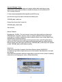
7
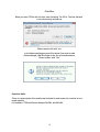
First Run:
When you start FSX for the first time after installing “Fw 190 A- The Late Variants”
a security warning will pop up:
Please answer this with “run”
In the following dialogue you will be asked if you wish to add
ClassicsHangar_XMLSound.gau to the list of trusted software.
Please answer with “Yes”.
Repainter Notes:
There is a layered paint kit in psd format included to make easier the creation of user
made repaints.
It’s located in “FSXroot\Classics Hangar\Fw190A_late\Paintkit”
8
Development
Fw 190 A-5
Changes in fighter tactics required more and more the use of external drop tanks to
increase flight duration, the now more widely use of the Fw190 as a fighter bomber
naturally led to an increased use of externally carried bombs.
In order to keep the Centre of Gravity intact when flying with external payloads the engine
was moved forward by 152 millimetres (apr. 5 inch) on the Fw 190 A-5 and all following
“Anton's”. Many think this change did a lot to the overall visual appearance of the plane.
With the A-5 blind flying and radio navigation equipment was introduced to the Fw 190
increasing the aircraft's capabilities to meet the requirements for a broader range of
mission profiles.
The pilot could now relate on an artificial horizon and a radio beacon indicator, the AFN-2,
though those changes were initially not well liked by the crews, being trained and used to
pure VFR flying. The artificial horizon was build into a housing combining a turn
coordinator ('Wendezeiger'), a slipball ('Libelle') and an artificial horizon ('künstlicher
Horizont') into a single instrument, the Wendehorizont. Three different types of the
Wendehorizont from different manufacturers can be identified in the Fw 190 A, all three
being technically identical, just differing in visual appearance.
Like the earlier variants, the A-5 could be flown with or without the outboard MGFF'M' 20
mm cannons.
A number of modifications were tested with A-5 airframes under different “U”
designations, amongst them MW-50 Methanol-Water injection, a “wet “emergency power
to increase performance for a limited period of time. Trials proofed unsuccessful so that
MW50 was never used operational in a BMW 801- equipped Fw190 serial production
aircraft.
Production of the A-5 began by November 1942, approximately 1752 left the factories until
August 1943.
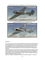
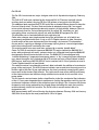
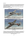
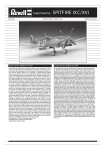
Fw190A-5 of 2./JG 11, Husum, Germany, Summer 1943.
9
Fw190A-5 of Walter Nowotny, Staffelkapitaen of 1./JG 54, Eastern Front 1943.
Fw190A-5 of Uffz. Bernhard Kunze of 1./JG 1, Netherlands, August 1943,
equipped with MGFF'M' 20 mm outboard cannons
Fw 190 A-6
The replacement of the drum-fed outboard MGFF cannons with the belt-fed Mg 151/20 E
led to the introduction of the new Fw 190 A-6 by June 1943. Some other improvements
were implemented such as increased armour around the oil cooler, however the only
visible differences were the longer MG 151/20 barrels and their under wing access
hatches which were differently shaped on each wing, empty shells now being ejected
outwards.
During the production course the main wheels were replaced with new types and a gun
camera was often seen on the left wing's leading edge. The PR 16 Loop Antenna was a
regular sight from late 1943 onwards and the pilot's headrest received two additional
support cables. The inner gear doors did no longer retract automatically when the gear
was fully extended from the A-6 onwards.
Only minor changes were applied to the cockpit to reflect the changes in armament:
10
The MGFF ammunition counter was dropped, the SZK K4 ammunition counter was
rewired for use with the four wing cannons, the nose machine guns only used an indicator
lamp from now on.
The majority of the approximately 1192 Fw 190 A-6 that left the factories until February
1944 served in the defence of the Reich, with the Fw 190 being more and more pressed into
the bomber destroyer role.
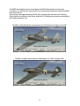
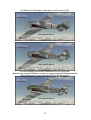
Fw190A-6 of Erich Rudorffer, Kommodore of II./JG 54 Immola, Finland, June 1944.
Fw190A-6 of Hptm. Horst Ademeit, Kommodore of I./JG 54, Summer 1944.
11
Fw 190 A-7
The weak fire-power of the 7.92mm Mg 17 – contemptuously nick-named “LuftwaffeAnklopf-Gerät” by the crews (Luftwaffe-knock-on-the-door-apparatus) was an ongoing
source of dissatisfaction. Consequently it had been replaced with the more vital 13mm Mg
131 as it became available, leading to the Fw 190 A-7 production beginning by November
1943.
The considerably larger and heavier Mg131 required changes to the upper nose area of the
aircraft: The firing channel's horizontal distance had to be increased from 200 mm to 260
mm requiring a reshape of the upper engine nacelle, the upper gun fairing now showed
some prominent bulges.
The cockpit saw a number of changes: The Revi 12 D gun sight was replaced with a Revi 16
B, some of the main flight instruments were replaced with newer types, the left console
was simplified, most noticeable the so-called 12-Lampen-Gerät (12-lamp-apparatus, gearflap indicator) was dropped. Flap indication was now provided by two small mechanical
indicators, the gear position was now indicated by a 4-Lampen-Gerät.
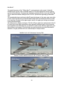
Fw190A-7 of 2./JG 1, Dortmund, January 1944.
Fw190A-7 of Ofw. Wilhelm Lorenz, 3./JG 11, Husum, February 1944.
12
Fw 190 A-7/R2
With the ever increasing allied heavy bomber raids over occupied Europe and German
homeland it became apparent that the fire-power of the Fw 190 was not sufficient enough
to bring down a 4 engined bomber. It took 20 direct hits of the 20mm ammunition on
average to kill a “Viermot”.
Combat trials were made with various armament configurations, for instance twin MG151
were installed in an external blister under each wing with the Fw 190 A-5/U12
('Kanonenboot'=gunship'), increasing the armament to 6 MG151 cannons and two Mg 17
machine guns. However trials were of limited success as the blisters decreased the Fw
190's top speed by some 60 kph (37mph).
The U12 modification was relatively short-lived and as far as can be told today, only applied
to the A-5 variant.
A more convincing solution was promised with the implementation of the Rheinmetall
Borsig 30mm MK 108 cannon. 3 direct hits from an Mk108 safely downed a four-engined
bomber.
A first prototype installation was build into the Fw 190 V51, an Fw 190 A-6.
The Mk 108 replaced the outboard Mg 151 requiring a re-designed lower access hatch with
the shell ejection slot being located inboard of the hatch plus an additional blister on top of
the wing.
The modification was available in a serial production aircraft from the Fw 190 A-7 onward
under the designation “R2”.
Today there is proof for about 701 Fw 190 A-7 being build to various equipment conditions
between November 1943 and March 1944.
Fw190A-7/R2 of 2./JG 11, Rotenburg, March 1944.
13
Fw 190 A-8
The Fw 190 A series saw two major changes when the A-8 production began by February
1944:
The FuG 16 ZE radio was replaced by the improved FuG 16 ZY and an internally stored
auxiliary tank was added, carrying 115 litres (30 gallons) of extra fuel aft of the pilot.
The additional tank required the ETC 501 rack to be re-located 200mm forward to keep the
Centre of Gravity intact. The Aux Tank could also be adopted to carry GM-1, an oxygen
mixture that improved combustion above the engine's critical altitude. However, there is
currently only proof for 11 aircraft being build to so-called “R4” conditions so “wet”
emergency power continued to play no role with the BMW 801 equipped Fw 190 A.
The pitot tube was re-located outboard to the right wing tip.
Some other changes were implemented during the production run, all of which are
erroneously associated with the A-9 only or the F-8 fighter bomber in older literature:
A solid metal roll bar was implemented into the canopy, nick-named “Furchenzieher”
(furrow puller), requiring a redesign of the canopy's plexi glass to a more bulged shape
which was instantly well received by the crews.
The metal propeller was more and more replaced by a wooden “paddle blade”.
Some Fw 190 A-8 received the improved BMW 801 TU engine, basically a BMW 801 D-2
motor with peripherals (oil cooler, exhaust stacks etc.) collected from projected BMW 801
developments that did not materialize in time. The BMW 801 TU was equipped with
“erhöhte Notleistung” (augmented emergency power), a “dry” emergency boost allowing to
over-boost the engine for a limited period of 10 minutes up to the critical altitude of about
5500 meters, delivering 2050 PS/2021 HP (not to confuse with C-3 fuel injection as used in
F and G fighter bombers at low altitude).
The cockpit received a considerable overhaul. Most noticeable the addition of a variometer
gauge to the main panel. The AFN-2 beacon indicator was moved from the main panel to a
location right of the Revi 16 gun sight whereas the clock, previously occupying this space,
was moved to the forward right console. The right console saw some rewiring with many
of the electrical fuses and switches being relocated and a switch for the aux tank's fuel
pump added.
The left console received some further simplification in that the mechanical flap indicators
of the A-7 were now dropped without replacement, limiting flap position control to just the
mechanical indicators outside of the cockpit on top of the wings. The 4-Lampen-Gerät was
dropped as well, being replaced by four simple lamps indicating the main gear position,
mounted directly into the left console. The FuG16 radio's remote controls were redesigned as well.
With approximately 6655 aircraft leaving the factories between February 1944 and January
1945 the A-8 was by far the most produced Fw 190 of all types.
14
Fw190A-8 of Kurt Buehligen, Kommodore of JG 2, summer 1944.
Fw190A-8 of Uffz. Martin Ullmann, 9./JG 5, Herdla, Norway, March 1945.
Fw190A-8 of Major Karl Kennel, Commander of II./SG 2, May 1945.
Note the upper wing Mk 108 blisters as seen on some standard A-8 indicating that this
plane had provision to carry either MG 151/20 or Mk 108 cannons.
15
Fw 190 A-8/R2 'Sturmjäger'
Much has been written about the “Rammjäger”-Staffeln that had been formed from
October 1943 onwards, facts are mixed with glorification and legends and particularly utter
nonsense putting the Sturmjäger-Staffeln on the level of a suicide commando.
The Sturmstaffeln were made up of volunteers who were self-committed to an “especially
brave action against the enemy......to down a bomber on each sortie.....if needed by
ramming.” So read the declaration the pilots signed when joining.
This of course was far from the combat reality over hostile Europe and of course not every
pilot found a good shooting position on each mission but ramming was the absolute
exception. The Sturmstaffeln were quite successful as an elite unit though.
The special character of the Sturmstaffel mission profile required an aircraft that could
take a considerable amount of damage with additional protection for the pilot.
The radial engined Fw 190 A seemed well suited for the task so the first batch of
Sturmjäger were modified from A-6 serial production fighters.
The left and right cockpit sides were fitted with 5mm steel plates, the forward and lower
cockpit sides were stuffed with extra armour, too.
The triangular side windows were replaced with 30 mm armoured glass and another
piece of 30 mm armoured glass in a wooden frame was added to the sliding canopy's
sides, nick-named “Scheuklappen” (horse blinkers), considerably hampering visibility. The
aircraft's weight increased by some 132 Kg/291 lb so the nose machine guns were often
removed.
Initially the Sturmjäger modifications didn't use any special designation but were
preferably added to the Mk 108 equipped R-2 sub variant before they eventually reached
serial production under the designation “A-8/R8” by late 1944. The A-8/R2 Sturmjäger,
respectively the A-8/R8 were often fitted with the performance-increased BMW 801 TU.
The requirements for extra armour changed over time, steel plates were added to protect
the Mk 108 cannons and it's ammunition, the Scheuklappen were no longer called for
when the A-8/R8 entered production.
Fw190A-8/R2 with Sturmjäger modifications of Hptm. Wilhelm Moritz,
Kommodore of IV. (Sturm) / JG 3, Memmingen, June 1944.
16
Fw190A-8/R2 with Sturmjäger modifications of Uffz Paul Lixfeld,
6./JG 300 'Wilde Sau', December 1944.
Note the absence of the “Scheuklappen” on this and the following aircraft.
Fw190A-8/R2 with Sturmjäger modifications of Uffz. Willy Maximowitz,
IV (Sturm) / JG 3 'Udet'.
17
Fw 190 A-9
The final reincarnation of the Fw 190 A series didn't differ visually from the late production
A-8. Only difference being the BMW 801 S power egg delivering 2000PS takeoff power at
1.65ata and 2200PS using “erhöhte Notleistung”. The 12-bladed engine cooling fan was
replaced with a 14-bladed type.
Approximately 910 Fw 190 A-9 were build between September 1944 and February 1945
when the Fw 190 A production ended.
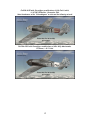
Fw190A-9 of 6./JG 301, Langensalza, April 1945.
Fw190A-9 of Wilhelm Ade, 2./JG 1, Twente, January 1945.
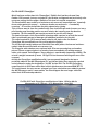
Fw 190 Today
The German aircraft restorer and manufacturer Flugwerk G.m.b.H. is currently producing
a lovingly recreated version of the Fw 190 A-8 under the designation “Fw 190 A-8/N” in
small numbers, the “N indicating “Neubau” = new construction. The first flying examples
were the Air Show Stars over Europe in 2009. For more information visit:
http://www.flugwerk.de
18
The Cockpit
This is a fairly well structured and logically arranged office. Almost everything is driven
and controlled electrically. The pilot’s workload is reduced to the absolute minimum
thanks to the so called “Kommandogerät”, a kind of early analogue computer based on
barometric conditions and throttle position, which controls all engine and propeller related
tasks such as setting spark points, mixture, prop pitch, loader stages and rpm, just by
working the throttle.
Operating the FS Aircraft
First, the aircraft can be started with CTRL+E if you choose so but you won't get very far if
you leave it at that. The aircraft systems require some attention in order to work correctly,
fuel should be burned in the correct sequence if you don't want to end your flight
prematurely with 100 gallons of unusable fuel, the altimeter's operational limits should be
taken serious and the engine deserves some special care.
There is no working 2d panel included.
The virtual 3d cockpit is fully functional and it’s visual quality should satisfy even the most
critical FS addict. All gauges and instruments are entirely modelled in 3d. The textures are
created using the latest industry standard rendering technologies, giving a depth and
sense of “being in the cockpit”. The aircraft can be entirely operated with the mouse from
within the virtual cockpit.
In the following we will discuss the technical/procedural details of operating some specific
cockpit systems in the aircraft.
Detailed start-up and flying procedures can be gathered from the in-flight check-lists and
references.
All gauges are in metric units, the labels are naturally in German language. However, to
serve an international audience, all buttons, levers, gauges and labels show an English
language tool tip when holding the mouse over them. All flight and engine gauges display
a tool tip in international units.
Farther on in the handbook is a description of the most important gauges which also
includes an “over the thump” Metric/International unit conversion so that the international
user should become accustomed to the metric system fairly fast.
Most systems are operated straight forward, however the radio, fuel usage, gear, trim and
flap operation may require a closer look and some practice to getting used to. This is
explained farther on in this document.
Most buttons and levers are operated by a single left click. Some items such as the gear
handle or the drop tank release use left click to pull and left-release to release.
Multi-position switches such as the bomb selector or the fuel tank display selector use
left and right clicks to step fore and back through the positions. Rotating items like the
compass rose can be dragged with the mouse or dialled with the mouse wheel.
A few items such as the fuses in the rear electrical panel are animated but don’t have a
specific FS function. This is to find a good balance between realism and usability. You
probably don’t want to push 20 buttons before your flight instruments work when
changing a plane in FS.
19
Some buttons and switches may not be easily in reach from within the default virtual
cockpit view. To come around this issue multiple camera views are arranged, accessible
using the “A” and “Shift + A” keys on the keyboard.
The FuG 16 Radio was only accessible from a service flap on the left fuselage side so
frequencies were pre-tuned and accessible by the pilot via some remote controls in the
left cockpit console. The pilot only had the option to fine-tune a pre-selected frequency
within a limited range. However, we have adopted the wartime cockpit remote controls so
that the virtual FS pilot can fully control and tune COM1, COM2 and NAV1 frequencies from
within the virtual cockpit, allowing for Voice Communication with the Tower and good oldfashioned VOR to VOR hopping. Since there was no visual indication for the selected
frequencies we use the FS tool tip system to gather feedback as you dial the Radios.
A detailed How-To can be found farther down in this document.
For convenience there's also the default 2d Pop-up Bendix Radio provided.
Flying at Night
There is no gauge back lighting in the Fw 190. However, dials and labels are painted with
“Leuchtpaste”, a fluorescent white paint that illuminates with a green glow in the dark.
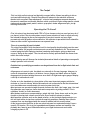
Forward Panel Fw 190 A-5, A-6, A-7 (A-7 uses some newer items)
20
Left Console Fw 190 A-5, A-6
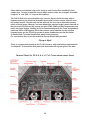
Right Console Fw 190 A-5, A-6, A-7
21
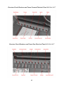
Overview Circuit Breakers and Fuses Forward Electrical Panel A-5, A-6, A-7
Overview Circuit Breakers and Fuses Rear Electrical Panel A-5, A-6, A-7
22
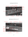
Cockpit Modifications Fw 190 A-7
Left Console A-7
Cockpit Modifications Fw 190 A-8, A-9
Main Panel A-8, A-9
23
Left Console A-8, A-9
Right Console Fw 190 A-8, A-9
24
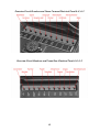
Overview Circuit Breakers and Fuses Forward Electrical Panel A-8, A-9
Overview Circuit Breakers and Fuses Rear Electrical Panel A-8, A-9
25
Specific Operation Procedures
Fuel Management
The engine always draws it's fuel from the Forward Tank, the Rear Tank feeds the
Forward Tank, Aux Tank (A-8, A-9) and Drop Tank both feed the Rear Tank.
The Fuel Lever in the lower forward panel opens the fuel valve.
The Fuel Content Display (lower Forward Panel) should be set to display Rear Tank
Content initially, Switch to Forward Tank Content when all but the Forward Fuel Tanks are
empty.
The fuel pumps (switches in right console, centre) transfer fuel among the tanks, allowing
for a proper fuel circulation:
1.) When flying with internal fuel only (Forward and Rear Tank) both the Forward Tank
Fuel Pump and the Rear Tank Fuel Pump are to be switched on. The Rear Tank
Fuel Pump is to be switched off as soon as the Rear Tank is empty to avoid that the
pump is running dry. Switch Fuel Content Display to Forward Tank.
2.) When Flying with Drop Tank all three the Forward-, Rear-, and Drop Tank Fuel
Pump are to be switched on initially. When the Drop Tank is empty, turn off the
corresponding Fuel Pump and release the empty Tank (red Lever, lower forward
panel). Continue as described in 1.). There is no indicator for Drop Tank Content.
The Drop Tank is empty as soon as the Rear Tank Fuel Content begins to drop.
3.) (A-8 and A-9) Flying with Aux Tank, proceed in the sense as described under 2.)
4.) (A-8 and A-9) Flying with a full fuel load (Forward, Rear, Drop Tank and Aux Tank)
The Aux Tank should be used first so that a somewhat unappreciative CoG shift
due to the extra fuel can be compensated. Forward-, Rear- and Aux Fuel Pumps
on initially until Aux Tank is empty (fuel warning lower forward panel, right hand).
Turn Off Aux Tank Fuel Pump, turn on Drop Tank Fuel Pump. Proceed as
described under 2.).
26
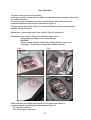
Gear Operation
The gear is driven by an electrical motor.
As the gear retracts, a pressurized air bottle is loaded which lowers the gear in the event
of an electrical failure.
The electrical gear switches are located in the left console fairly at the centre in a
combined instrument along with the flap switches (Figure 1).
The gear unlock mechanism (Figure 2) is located left hand in the lower forward panel,
labelled “Notzug Fahrwerk”.
Retract gear: remove safety cover from switch 2 (Figure 1) and press it.
Extend gear: press switch 1 (Figure 1) to activate the gear motor,
next pull the lever (Figure 2) to unlock the gear.
WARNING!
Always activate the gear motor before pulling the lever except in an
emergency. The gear can no longer be retracted otherwise.
Fig. 1
Fig. 3
Fig. 2
Fig. 4
Status indication is provided mechanically on top of the wings (Figure 3)
and electrically by a combined gear/flap indicator (Figure 4)
“Ein” Red light = Gear up
“Aus” Green light = Gear down
27
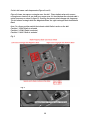
Flaps Operation
The flaps are operated electrically by push buttons in the left console.
Button 1 (Figure 1) Landing 60°
Button 2 (Figure 1) Take-off 12°
Button 3 (Figure 1) Fully retracted
Status indication is provided mechanically on top of each wing (Figure 2)
and electrically by a combined gear/flap indicator (Figure 3)
“Ein”, Red light = fully retracted
“Start” Orange light = 12° take-off position
“Aus” Green light = 60° landing position
Fig. 1
Fig.2
Fig. 3
Trimming
Aileron and rudder trim is not provided and not required. Static trim tabs can be adjusted
on the ground to level out production tolerances.
To adjust the aircraft as load changes the horizontal tail plane can be trimmed as a whole
by an electrical motor. A See-saw Button (left click-hold, right click-hold) is located in the
left console along with a trim indicator (Figure 1).
Fig. 1
28
Radio Operation (Fw 190 A-5 to A-7)
The wartime FuG 16 Radio's remote controls in the cockpit's left console are adopted to
provide some basic FS functionality from within the 3d environment. Since there were no
indicators of any sort we relate on the tool tip function within FS to gather feedback on the
switches and dial's status. Whom it is to cumbersome can use the default 2d Bendix radio
which is build into the aircraft.
A note on tool tips: There is a known bug in FSX that causes tool tips to not show up when
in DX10 preview and full screen mode. Workaround: Toggle Alt+Enter to go to windowed
mode.
The avionics main switch is located in the right consol's rear electrical panel.
First let's have a look at the switches (Figure 1):
Switch #1 Toggles COM 1 and COM 2 forth and back.
Switch #2 swaps the active Radio's standby frequency.
Switch #3 toggles whether you want to receive on both COM radios or on the active Radio
only.
Switch #4 toggles the NAV station's recognition audio signal.
Switch #5 swaps the NAV 1 Radio's standby frequency.
Fig. 1
29
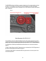
So let's dial some radio frequencies (Figure 2 and 3):
Figure 2 shows two square rectangles over the dial. These indicate where the mouse
rectangles are located. As you hold your mouse over it it should show the selected radio's
active frequency as shown in figure 3. Scrolling the mouse wheel changes the frequency.
The left mouse rectangle dials the Megahertz Band, the right rectangle dials the Kilohertz
Band.
Item 2 is a three-position switch that selects which Radio is active on the dial:
Position 1 : COM 1 Radio is selected
Position 2 : COM 2 Radio is selected
Position 3 : NAV 1 Radio is selected
Fig. 2
Fig. 3
30
The VOR OBS Heading is dialled on a mouse rectangle over the compass glass as shown
in Figure 4. The compass rose and AFN 2 direction indicator will adjust accordingly.
There are also alternative mouse rectangles over the AFN 2 beacon indicator that dial the
NAV 1 Frequency.
Fig. 4
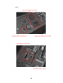
Radio Operation (Fw 190 A-8, A-9)
The installation of the new FuG 16 ZY Radio from the A-8 onwards required some of the
remote controls to be re-designed. Naturally we had to adopt the FS function buttons in a
different way, the functionality remains the same as with the A-5 to A-7 models however.
The COM Select, COM Swap and COM Receive Both Buttons are relocated as shown in
Figure 1
The NAV 1 Audio Signal and NAV 1 Swap function are relocated to the FuG 25 apparatus in
the lower left forward panel as shown in Figure 2.
The Avionics Main Switch is relocated within the right console rear electric panel to the
most forward position.
31
Fig. 1
32
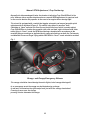
Manual RPM Adjustment, Prop Feathering
Normally the Kommandogerät takes the burden of adjusting Prop Pitch/RPM off of the
pilot. However there may be situations where a manual RPM adjustment is required such
as the need to feather the propeller in the event of an engine failure during flight.
The aircraft is equipped with a switch that toggles automatic and manual propeller pitch
adjustment forth and back (Figure 1). The switch is by default in position “Auto”.
Switching to “Hand” activates the See-Saw on the throttle lever which is used to adjust
Prop Pitch/RPM or to feather the propeller (left-click and hold, right-click and hold). Note
when flying in “Hand”- mode the RPM should always be adjusted in accordance to the
manifold pressure settings as indicated by the coloured markings on both the Tachometer
and Manifold Pressure Gauge! Flying above 2500 RPM in “Hand”- mode should be avoided!
Fig. 1
Canopy and Canopy Emergency Release
The canopy should be closed during the entire flight (risk of canopy blowing off).
In an emergency event the canopy can be blasted using a charge.
A red lever is located on the right cockpit wall just aft of the canopy hand wheel.
Pressing it once arms the charge,
pressing it twice detonates the charge.
33
Main Flight and Engine Instruments
Altimeter FL.22320
0 – 10.000 meters (32.808ft)
Meters Needle, one revolution = 1000
Meters
Kilometres Disk
Calibration Knob
Barometric Pressure in Millibar
Metric Conversion:
1.000 Meters = 1 Kilometre = 3.281 ft
3.000 Meters = 9.843 ft
6.000 Meters = 19.685 ft
Airspeed Indicator FL.22231
(A-5, A-6)
0 – 750 Kilometres per Hour (466 mph)
Metric Conversion:
100 kph = 62 mph
200 kph = 124 mph
300 kph = 186 mph
400 kph = 249 mph
500 kph = 311 mph
600 kph = 373 mph
700 kph = 435 mph
750 kph = 466 mph
Airspeed Indicator FL.22234
(A-7, A-8, A-9)
0 – 900 Kilometres per Hour (559 mph)
Metric Conversion:
100 kph = 62 mph
200 kph = 124 mph
300 kph = 186 mph
400 kph = 249 mph
500 kph = 311 mph
600 kph = 373 mph
700 kph = 435 mph
750 kph = 466 mph
34
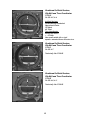
Combined Artificial Horizon,
Slip Ball and Turn Coordinator
Fl 22410
Fw 190 A-5, A-6
Artificial horizon:
Locked during Aerobatics!
Operational Limits:
110° Bank
60° Pitch
Turn Coordinator:
electrically driven
+ - 35° Max
One needle width left or right
equals a standard three-minutes-turn.
Combined Artificial Horizon,
Slip Ball and Turn Coordinator
Fl 22411
Fw 190 A-7
Technically like Fl 22410
Combined Artificial Horizon,
Slip Ball and Turn Coordinator
Fl 22415
Fw 190 A-8, A-9
Technically like Fl 22410
35
Heading Indicator FL.23334
electrically driven slave
The aircraft symbol is the rotating part.
The rose can be adjusted so that the
desired course points to the top for easier
readability. Also tunes OBS heading.
Tachometer FL.20222-2
Fw 190 A-5, A-6
500 – 3000 rpm
Markers for Max Continous, Max Climb and
Max Takeoff. Note The Manifold Pressure
Gauge should be used to set power!
Tachometer FL.20222-3
Fw 190 A-7, A-8, A-9
500 – 3600 rpm
Markers for Max Continous, Max Climb and
Max Takeoff. Note The Manifold Pressure
Gauge should be used to set power!
36
Manifold Pressure FL.20555
0.6 – 1.8 atmospheres absolute
Typical Max Continuous Power setting
1.15 – 1.2 ata = 34.36 – 35.88 inHG
Fuel/Oil Pressure
FL.20512-3
Left: Fuel Pressure 0 – 2 kg/cm²
Normal operation 1.25 – 1.75 kg/cm²
Right: Oil Pressure 0 – 15 kg/cm²
normal operation 8 – 9 kg/cm²
Oil Temperature FL.20342-2
0 - 120°C
Fuel Content Indicator FL.20723
Upper dial 0 – 300 litres (rear tank)
Lower dial 0 – 230 litres (forward tank)
Displays either rear or front tank content.
NOTE: Yellow Selector Switch FL.32331
to the right of the gauge.
37
Prop Pitch Indicator FL.18503-2
Works like a clock.
12:35 = 25° Pitch
10 minutes on the dial equal 1° of Pitch
Fuel Content Display Selector FL.32331
Toggles the Fuel Content Indicator to either
display Rear or forward tank content.
Centre = Off
Right (see picture) = Rear Tank
Left = Forward Tank
AFN-2 Radio Beacon Indicator
Ln.27002
Vertical needle indicates course deflection
Horizontal needle indicates distance to
selected VOR station.
Indicated range: 60 – 0 nautical miles
''Rich' Lever (Anreicherungszug)
Pull this once before engine start to bring the
Kommandogerät to start-up conditions.
Sets mixture to “Rich” and prop pitch to
default angle.
38
Changing or removing Payloads
The Fw 190 is by default equipped with a 300 Litres Drop Tank but can be alternatively
equipped with an SC 250 bomb or no payload at all using the FS X Payload Editor.
When removing all Payloads the fixed inner gear covers are automatically replaced with
retractable gear doors.
Proceed as follows:
-
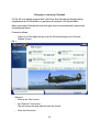
(Figure 1) In Free flight with any of the Fw 190 A selected go to the “Fuel and
Payload” screen.
Fig. 1
(Figure 2)
- Click on the “Fuel” screen
-
Set “External 1” fuel to zero.
This will remove the drop tank fuel from the aircraft.
-
Close the Fuel screen
39
Fig. 2
-
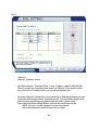
(Figure 3)
Open the “Payloads” screen.
-
Set Station Weight 1 “Drop tank Pylon” to zero (“Trigger” weight is 70kg/154.3lb).
This will remove the visual drop tank model and it’s pylon. If you leave it at that
your aircraft is now configured to carry no external payload at all.
-
Set Station Weight 2 “Bomb Pylon” to at least 49Kg or 108lb depending on the units
set up you have configured your Simulation to use. This will add the weight of the
pylon inclusive apparatuses and makes the bomb and it’s pylon visible.
If you wish add another 250Kg/550lb to simulate the actual bomb weight
NOTE: You won’t see the changes in the preview window.
The bomb will become visible as you start your flight.
40
Fig. 3
Dropping the Bomb
- Fuse the bomb using the bomb mode selector switch (Figure 4, Pos. 1).
Any position other than the default “Aus” will do fine.
A red light (Figure 4, Pos. 3) will glow once the bomb is successfully fused.
-
Release the bomb by clicking fire button 2 on the stick (Figure 4, Pos. 2)
Using the fire button will also trigger the FS event
“RELEASE_DROPPABLE_OBJECTS”
so it can be used in mission scenarios to do just that. Note Mission Creators can
access the SC250 bomb from the SimObjects\misc folder as a droppable object.
41
Fig. 4
42
Project Team:
Gofer, Project Lead, Visual Models,
Interior Textures and Programming.................. Mathias Pommerien
Exterior Textures,
Texture Manager Application............................ Alessandro Biagi
Aero Files......................................................... AvHistory/Gregory Pierson
Engine Sounds.................................................. Steve Buchanan
Beta Testing..................................................... Huub Vink, Roger Law
Special thanks to Warwick Carter, Chuck Jodry, Bill Leaming and teson1 for their
invaluable help.
43