1
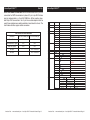
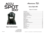
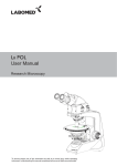
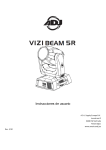
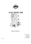
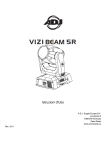
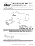
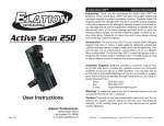
American DJ
®
Accu Spot 250 II™
Table of Contents
User Instructions
7/05
American DJ®
4295 Charter Street
Los Angeles CA. 90058
www.americandj.com
Unpacking......................................................................3
Introduction....................................................................3
Customer Support......................................................................3
Safety Precautions......................................................................4
Features.........................................................................5
RDMX..........................................................................................5
Handling Precautions..................................................................6
Discharge Lamp Warnings..........................................................6
Registration......................................................................7
Controls and Functions...............................................................8
Set-Up.............................................................................11
System Menu............................................................................14
Editing Program.........................................................................30
Operating Modes.......................................................................33
Fuse and Lamp Replacement...................................................35
DMX Traits.................................................................................37
Gobos..................................................................................38
Gobo Replacement...................................................................43
Opitional Lens...........................................................................44
Cleaning..................................................................45
Trouble Shooting.......................................................................45
Warranty.........................................................................46
Specifications....................................................................47
American DJ® - www.americandj.com - Accu Spot 250 II™ Instruction Manual Page 2
Accu Spot 250 II™
General Information
Unpacking: Thank you for purchasing the Accu Spot 250 II™ by
American DJ®. Every Accu Spot 250 II™ has been thoroughly tested
and has been shipped in perfect operating condition. Carefully check
the shipping carton for damage that may have occurred during shipping. If the carton appears to be damaged, carefully inspect your fixture for any damage and be sure all equipment necessary to operate
the unit has arrived intact. In the event damage has been found or parts
are missing, please contact our toll free customer support number for
further instructions. Please do not return this unit to your dealer without contacting customer support first.
Introduction: The Accu Spot 250 II™ is a eight channel or nine channel, moving head, intelligent DMX fixture. The fixture can operate in
three different operating modes; stand alone, sound-active, or in a
Master/Slave configuration. The Accu Spot 250 II™ comes with several built in programs and is best used in multiples of four. When used
as a stand alone unit or when used in multiples linked in a master/
slave configuration. For best results use fog or special effects smoke
to enhance the beams projections.
During the initial start-up or use of this product a light smoke or
smell may arise from the unit. This is a normal process and is
cause by the heat associated with the lamp.
Customer Support: American DJ® provides a toll free customer
support line, to provide help and to answer any question should you
encounter problems during your set up or initial operation. You may
also visit us on the web at www.americandj.com for any comments or
suggestions. Service Hours are Monday through Friday 9:00 a.m. to 5:
00 p.m. Pacific Standard Time.
Voice:
(800) 322-6337
Fax:
(323) 582-2610
E-mail:
[email protected]
To purchase parts online visit http://parts.americandj.com
Warning! To prevent or reduce the risk of electrical shock or fire, do
not expose this unit to rain or moisture.
Warning! This may cause severe eye damage. Avoid looking directly
into the light source at all times!
American DJ® - www.americandj.com - Accu Spot 250 II™ Instruction Manual Page 3
Accu Spot 250 II™
Safety Precautions
For Your Own Personal Safety, Please Read and Understand This
Manual Completely Before You Attempt To Install Or Operate
This Unit!
• To reduce the risk of electrical shock or fire, do not expose this unit
rain or moisture
• Do not spill water or other liquids into or on to your unit.
• Be sure that the local power outlet match that of the required voltage for your unit.
• Do not attempt to operate this unit if the power cord has been
frayed or broken.
• Do not attempt to remove or break off the ground prong from
the electrical cord. This prong is used to reduce the risk of electrical
shock and fire in case of an internal short.
• Disconnect from main power before making any type of connection.
• Do not remove the cover under any conditions. There are no user
serviceable parts inside.
• Never operate this unit when it’s cover is removed.
• Always be sure to mount this unit in an area that will allow proper
ventilation. Allow about 6” (15cm) between this device and a wall.
• Do not attempt to operate this unit, if it becomes damaged.
• This unit is intended for indoor use only, use of this product outdoors voids all warranties.
• Always mount this unit in safe and stable matter.
• Power-supply cords should be routed so that they are not likely to
be walked on or pinched by items placed upon or against them,
paying particular attention to cords at plugs, convenience receptacles, and the point where they exit from the appliance.
• Cleaning -The fixture should be cleaned only as recommended by
the manufacturer. See page 44 for cleaning details.
• Heat -This fixture should be situated away from heat sources such
as radiators, heat registers, stoves, or other appliances (including
amplifiers) that produce heat.
• The fixture should be serviced by qualified service personnel when:
A. Objects have fallen, or liquid has been spilled into the appliance.
B. The appliance has been exposed to rain or water.
C. The appliance does not appear to operate normally or exhibits a
marked change in performance.
American DJ® - www.americandj.com - Accu Spot 250 II™ Instruction Manual Page 4
Accu Spot 250 II™
Features
• Micro-Stepping Motors for Smooth Color and Gobo Transitions
• 2 Modes of DMX-512 Protocol Compatible (Eight DMX Channel
Mode or Nine DMX Channel Mode)
• Independent Gobo and Color Wheels
• 7 Rotating Gobos, 2 Dichoric + Spot - All Replaceable
• 9 Colors, Plus White - With Rainbow
• RDMX - Lets you set the DMX address from any DMX Controller
• 3 Operating Modes - Master/Slave; Stand Alone; Sound Active
• Internal Microphone
• ZB-MSD250 Discharge Lamp, 230v/250w
• Edit and Save Scenes into the Memory
• Manual Focus Lens
• 360˚ Pan Movement
• 265˚ Tilt Movement
• Digital Display for Address and Function Setting
Accu Spot 250 II™
RDMX
Regarding RDMX :
1. The units will be shipped preset in 16 channel increments
from the factory
2. While using RDMX, if all units are set to the same DMX
address, all units will change to the new DMX address you
selected.
EXAMPLE: You have four units, and all the units are set to the
DMX address of “1”, and you change one unit to DMX address
“17”, this will cause all the units to change to DMX address
“17”.
All four units must be on 4 different starting addresses to individually set the DMX addresses for each unit.
For more on this feature see pages 24-25.
American DJ® - www.americandj.com - Accu Spot 250 II™ Instruction Manual Page 5
Accu Spot 250 II™
Handling Precautions
Caution! There are no user serviceable parts inside this unit. Do not
attempt any repairs yourself, doing so will void your manufactures
warranty. In the unlikely event your unit may require service please
contact American DJ®.
During operation the housing may become extremely hot. Avoid
touching the unit with bare hands while in use.
American DJ® will not accept any liability for any resulting damages
caused by the non-observance of this manual or any unauthorized
modification to this unit.
Accu Spot 250 II™
Discharge Lamp Warning
This fixture is fitted with a discharge lamp which
is highly susceptible to damage if improperly
handled. Never touch the lamp with your bare fingers as the oil from your hands will shorten lamp
life. Also, never move the fixture until the lamps
have had ample time to cool. Remember, lamps
are not covered under warranty conditions.
This unit emits intense UV radiation which is harmful to the eyes and
skin. The intense luminance of the lamp can cause severe damage
to the retina. Never operate this unit without it’s covers, these covers
have been specially designed to shield against UV radiation.
Epileptic Warning: Those suffering from epilepsy should avoid looking
directly into the lamp at all times.
Avoid switching the fixture on and off repeatedly in short intervals as
this will reduce lamp life and intensity.
To achieve the intensity associated with discharge lamps, these lamps
use gas sealed in a high pressure environment to emit a brilliant output.
Due to the high pressure involved with the construction of the lamp,
the lamp may explode during prolonged extensive use. This risk is
increased with age, added care is encouraged when dealing with older
lamps. Extreme caution should be used when operating this or any
fixture fitted with a gas discharge lamp. Never open this unit while in
use.
American DJ® - www.americandj.com - Accu Spot 250 II™ Instruction Manual Page 6
Accu Spot 250 II™
General Instructions
To optimize the performance of this product, please read these operating
instructions carefully to familiarize yourself with the basic operations of
this unit. These instructions contain important safety information regarding the use and maintenance of this unit. Please keep this manual with
the unit, for future reference.
Accu Spot 250 II™
Accu Spot 250 II™
Controls and Functions
FRONT
Product Registration
The Accu Spot 250 II™ carries a one year limited warranty. Please fill
out the enclosed warranty card to validate your purchase. All returned
service items whether under warranty or not, must be freight pre-paid
and accompany a return authorization (R.A.) number. The R.A. number
must be clearly written on the outside of the return package. A brief
description of the problem as well as the R.A. number must also be
written down on a piece of paper and included in the shipping carton.
If the unit is under warranty, you must provide a copy of your proof of
purchase invoice. You may obtain a R.A. number by contacting our
customer support team on our toll free customer support number. All
packages returned to the service department not displaying a R.A.
number on the outside of the package will be returned to the shipper
at the shippers cost.
REAR
13
12
7
14
American DJ® - www.americandj.com - Accu Spot 250 II™ Instruction Manual Page 7
15
12
American DJ® - www.americandj.com - Accu Spot 250 II™ Instruction Manual Page 8
Accu Spot 250 II™
Controls and Functions
1. Lens Assembly - This high quality lens is a fully focusing. Focus
the lens by manually turning the lens in a clockwise or counter-clockwise direction until the desired effect is achieved.
2. Digital Display - This display shows the menu and operating functions that you can choose from.
3. Mode/Esc Button - This button is used to enter the main menu and
submenus. It is also used to exit.
4. Up Button - This button is used to scroll forwards when navigating
through the system menu.
5. Down Button - This button is used to scroll backwards when navigating through the system menu.
6. Enter Button - This button is used to select and confirm a function
in the system menu.
7. Carrying Handles - The includes built-in carrying handles. Be sure
to always handle the unit by the built-in handles. Never lift or carrying the unit by head or yoke. Pulling on or transporting the unit by the
moving head may severely damage the unit and will void the unit warranty.
8. XLR Output Jack - This jack is used to transmit the incoming
DMX signal to another DMX fixture, or transmit a Master/Slave signal
to the next Accu Spot 250 II™ in the chain. For best results in DMX or
Master/Slave mode terminate this jack if it is the last unit in the chain.
See “Terminator” on page 11.
9. XLR DMX Input Jack - This jack is used to receive an incoming
DMX signal or Master/Slave signal.
10. Mini/C Controller Jack - This jack is for use with the optional
Mini/C controller only. Do not attempt to connect an audio signal to
this jack, this will damage the PC board and void your manufactures
warranty!
Accu Spot 250 II™
Controls and Functions
12. Cooling Fan - This unit is equipped with three high velocity variable fans to aid in the cooling process. These fans are designed to
vary their velocity at different operating temperatures, to provide
better cooling when the unit reached higher operating temperatures
associated with long usage. Be sure to never obstruct the cooling fans
during normal usage. Also, be sure to keep the vents clean at all times.
A blocked or malfunctioning cooling system may shorten lamp life and
unit reliability.
13. Lamp Assembly and Access Plate - This plate accesses the lamp
socket assembly. The unit includes a spring mounted ZB-MSD250
230v/250w discharge lamp. Be sure to only replace with same type
lamp. After replacing a lamp be sure the lamp is centered in the reflector. See page 35 for details on installing and optimizing replacement
lamps. Never operate this unit with the lamp exposed, this lamp emits
strong UV radiation.
14. Fuse Holder - This housing stores a 8 amp (4 amp 220v) GMA protective fuse. Never defeat the fuse, the fuse is designed to protect the
electronics in the event of severe power fluctuations. Always be sure
to replace the fuse with an exact match as the one being replaced,
unless otherwise told to do so by an authorized American DJ® service
technician.
15. Power Cord Inlet - This unit is equipped with a removable I.E.C.
power cord. Be sure to only use the power cord included with the
unit, this cord is designed to match the electrical requirements of the
unit. Other cords may cause the unit to overheat or malfunction. Voltage may vary from venue to venue, when connecting this unit to a
power supply be sure to connect to a matching power outlet. Never
use this fixture if the ground prong has been removed or broken off.
The ground prong is designed to reduce the risk of fire or electrical
shock in the event the unit suffers from an internal short.
11. Microphone - This microphone receives external low frequencies
to trigger the unit in Sound-Active mode. This microphone is designed
to receive low frequency sounds only, tapping on the microphone and
high pitch sounds may not trigger the unit.
American DJ® - www.americandj.com - Accu Spot 250 II™ Instruction Manual Page 9
American DJ® - www.americandj.com - Accu Spot 250 II™ Instruction Manual Page 10
Accu Spot 250 II™
Set Up
Accu Spot 250 II™
Power Supply: Before plugging your unit in, be sure the source volt-
INPUT
OUTPUT
2
DMX +
DMX -
Figure 1
American DJ® - www.americandj.com - Accu Spot 250 II™ Instruction Manual Page 11
SOUN
POWER
1
2
DMX +
3
DMX -
3
1
DMX512 IN
3-PIN XLR
2
3
1
2
Figure 2
XLR Female Socket
XLR Male Socket
1 Ground
REMOTE
CONTROL
INPUT
SOUND
2 Cold
2 Cold
INPUT
OUTPUT
1 Ground
3 Hot
XLR Pin Configuration
Pin 1 = Ground
REMOTE
CONTROL
SOUND
INPUT
OUTPUT
INPUT
Pin 2
= Data Compliment (negative)
3 Hot
Pin 3 = Data True (positive)
Figure 3
Special Note: Line Termination. When longer runs of cable are
POWER
POWER
used, you may need to use a terminator on the last unit to avoid erratic
behavior. A terminator is a 90-120 ohm 1/4 watt resistor which is connected between pins 2 and 3 of a male XLR connector (DATA + and
DATA -). This unit is inserted in the female XLR connector of the last
unit in your daisy chain to terminate the line. Using a cable terminator
(ADJ part number Z-DMX/T) will decrease the possibilities of erratic
behavior.
COMMON
3
OUTPUT
COMMON
DMX512 OUT
3-PIN XLR
DMX+,DMX-,COMMON
1
INPUT
DMX+,DMX-,COMMON
cables. Do not use
the ground lug on the XLR connector. Do not connect the cable’s shield conductor to the ground lug or allow the shield
conductor to come in contact with the XLR’s outer casing. Grounding
the shield could cause a short circuit and erratic behavior.
POWER
Data Cable (DMX Cable) Requirements (For DMX
and Master/Slave Operation): The Accu Spot 250
II™ can be controlled via DMX-512 protocol. The
Accu Spot 250 II™ can be a eight or nine channel
DMX unit. The DMX address is set electronically
using the controls on the side panel of the unit.
DMX512 OUT
3-PIN XLR
Your unit and your DMX controller require a standard 3-pin XLR connector for data input and data
REMOTE
CONTROL
INPUT
SOUND
Notice: Be sure to follow
figures two and three when making your own
DMX512
tocol used by most lighting and controller manufactures as a form of
communication between intelligent fixtures and controllers. A DMX
controller sends DMX data instructions from the controller to the fixture. DMX data is sent as serial data that travels from fixture to fixture
via the DATA “IN” and DATA “OUT” XLR terminals located on all DMX
fixtures (most controllers only have a DATA “OUT” terminal).
REMOTE
CONTROL
INPUT
OUTPUT
POWER
DMX-512: DMX is short for Digital Multiplex. This is a universal pro-
SOUND
Set Up
INPUT
output (Figure 1). If you are making your own cables, be sure to use
standard two conductor shielded cable (This cable may be purchased
at almost all professional sound and lighting stores). Your cables
should be made with a male and female XLR connector on either end
of the cable. Also remember that DMX cable must be daisy chained
and cannot be split.
age in your area matches the required voltage for your American DJ®
Accu Spot 250 II.™ The American DJ® Accu Spot 250 II™ is available
in a 120v and 220v version. Because line voltage may vary from venue
to venue, you should be sure your unit voltage matches the wall outlet
voltage before attempting to operate you fixture. Also be sure to only
use the included I.E.C. power cable supplied with the unit, this cable
matches the voltage and current requirements of the unit.
DMX Linking: DMX is a language allowing all makes and models
of different manufactures to be linked together and operate from a
single controller, as long as all fixtures and the controller are DMX
compliant. To ensure proper DMX data transmission, when using
several DMX fixtures try to use the shortest cable path possible. The
order in which fixtures are connected in a DMX line does not influence
the DMX addressing. For example; a fixture assigned a DMX address
of 1 may be placed anywhere in a DMX line, at the beginning, at the
end, or anywhere in the middle. Therefore, the first fixture controlled
by the controller could be the last fixture in the chain. When a fixture
is assigned a DMX address of 1, the DMX controller knows to send
DATA assigned to address 1 to that unit, no matter where it is located
in the DMX chain.
DMX512
REMOTE
CONTROL
INPUT
SOUND
3
1
2
DMX512 IN
3-PIN XLR
3
1
2
Termination reduces signal errors and
avoids signal transmission problems
and interference. It is always advisable
to connect a DMX terminal, (Resistance
120 Ohm 1/4 W) between PIN 2 (DMX-)
and PIN 3 (DMX +) of the last fixture.
Figure 4
American DJ® - www.americandj.com - Accu Spot 250 II™ Instruction Manual Page 12
Termination
avoids sign
and interfere
to connect a
120 Ohm 1/4
and PIN 3 (
Accu Spot 250 II™
Set Up
Accu Spot 250 II™
System Menu
5-Pin XLR DMX Connectors. Some manufactures use 5-pin XLR
connectors for DATA transmission in place of 3-pin. 5-pin XLR fixtures
may be implemented in a 3-pin XLR DMX line. When inserting standard 5-pin XLR connectors in to a 3-pin line a cable adaptor must be
used, these adaptors are readily available at most electric stores. The
chart below details a proper cable conversion.
3-Pin XLR to 5-Pin XLR Conversion
Conductor
3-Pin XLR Female (Out)
5-Pin XLR Male (In)
Ground/Shield
Pin 1
Pin 1
Data Compliment (- signal)
Pin 2
Pin 2
Data True (+ signal)
Pin 3
Pin 3
Not Used
Pin 4 - Do Not Use
Not Used
Pin 5 - Do Not Use
1
ADDR
A001~A511
2
3
TEST
AUDI
T-01~T-XX
MSTR
ALON
Indicate the staring DMX address
A001 also is the setting for slave
Automatically test the function
Runs fixture as “master” for audio
Runs fixture as “alone” for audio
4
5
LAMP
RESE
ON/OFF
ALL
SCAN
COLR
Manually switches lamp “on” and “off”
Reset all motors and returns fixture to home
Reset only motors for pan/tilt
Reset only motors for colors
GOBO
SHTR
Reset only motors for gobo and rotation
Reset only motors for shutter and/or dimmer
6
TIME
7
8
9
RPAN
RTLT
DISP
12
SPEC
13
EDIT
LIFE
LAMP
Displays the total fixture running time
Displays a lamps running time
CLMP
Clear lamp running time
ON/OFF
ON/OFF
VALU
D ON
FLIP
LAAU
D–XX D-00 (DXXX)
ON/OFF
ON/OFF
ON/OFF
Reverses the pan movements
Reverses the tilt movements
Display the DMX512 value of each channel
Display turn off after 2mins
This function will reverse the display 180
Automatic lamp start with power
RDMX
ON/OFF
MODE
8 CH/9CH
DLOF
DLAY
SPOT
DFSE
FEED
VER
STEP
SCXX
ON/OFF
D–XX D-15
ON/OFF
ON/OFF
ON/OFF
V1.0~V9.9
S–01 ~S–48
C–01
:
C–30
TIME
CEDT
ON/OFF
RUN
American DJ® - www.americandj.com - Accu Spot 250 II™ Instruction Manual Page 13
0000~9999
0000~9999
Change DMX address via external
controller
Switch between 8channels or 9 channels
Switch lamp via DMX
Lamp on delay time
Lamp optimization
Resets all the fixture functions to default
Pan/tilt feedback (error correction) on/off
Software version
Set the amount of your program
0 1 XX(00~FFH)
:
3 0 XX(00~FFH)
T – XX(01~FFH)
ON/OFF
Program test
American DJ® - www.americandj.com - Accu Spot 250 II™ Instruction Manual Page 14
Accu Spot 250 II™
System Menu
Accu Spot 250 II™
System Menu
ADDRESS MENU -
DISPLAY MENU -
A001 - A511 - This is where you set the DMX address of the unit.
VALU (DMX-512 Value) - Display the DMX-512 value of each
channel.
TEST MENU T-01 - T-XX - Tests the functions of each channel. There are
eight channels, but only channels 1,2,3,4, and 6 can be tested.
D ON - Turns digital display off after 2 minutes.
AUDI MENU -
SPEC MENU -
ALON (Alone) - Unit runs in stand alone mode, no master/slave.
LAAU - On/Off Automatically switches on lamp when power is
applied.
MAST (Master) - Designates that unit to be master in master/
slave mode.
LAMP MENU ON/OFF - Manually switches the lamp “On” or “Off”.
RESE (RESET) MENU ALL - Resets all motors.
SCAN - Resets the pan/tilt motors.
COLR (Color) - Resets the color wheel motor.
GOBO - Resets the gobo wheel motor.
SHTR (Shutter) - Resets the shutter and dimmer motors.
TIME MENU -
FLIP - “Flips” the digital display 180º.
RDMX - On/Off With this function you are able to change the
DMX address via external controller. See pages 25-26.
MODE - 8Ch/9Ch With this function you can switch between 8
channels and 9 channels. See pages 37-39 for the 8 Channel
mode DMX traits, and 40-42 for 9 Channel mode DMX traits.
DLOF (Lamp Adjustment) - With this function you can adjust the
lamp via the control board. In this mode, the device will not
react to any control signal.
DLAY - With this function you can put the lamp on a delay time.
SPOT - This provides a spot beam for better lamp optimization.
DFSE - This will reset the unit to the default settings.
LAMP - Displays the lamp running time.
FEED - With this function you can activate or deactivate the
pan/tilt error correction. So if you units head gets knocked out
of place the unit will automatically go back to the last setting.
CLMP - Clears the lamp running time.
VER - This will display the software version
RPAN MENU -
EDIT MENU -
ON/OFF - Reverses the pan.
STEP (Step) - Steps to be used in Edit Programming. See ediit
program. See page 30.
LIFE - Displays the total fixture running time.
RTLT MENU ON/OFF - Reverses the tilt.
American DJ® - www.americandj.com - Accu Spot 250 II™ Instruction Manual Page 15
SCO1 - SC48 (Scene 01 - Scene 48) - These are the scene slots
that you write your programs into. See edit program, pages 30
American DJ® - www.americandj.com - Accu Spot 250 II™ Instruction Manual Page 16
Accu Spot 250 II™
System Menu
- 32.
Accu Spot 250 II™
System Menu
On-Board System Menu. The Accu Spot 250 II™ comes with an
TIME (Time) - Time for each scene. See pages 30 - 32.
easy to navigate system menu. This next section will detail the functions of each command in the system menu.
CEDT - Edit program using a external controller. See pages 30
- 32.
Enter Button - To access the main menu locate the ENTER button (6)
C-01 - C-30 (Channel 1 - Channel 30) - The channels of each
scene that can be edited. See pages 30 - 32.
on the front of the unit. Press this button to activate the system menu.
Tap the UP button (4) until you reach function you wish to change.
When you reach the function you wish to change tap the ENTER button.
When a function is selected the menu will begin to flash, use the UP
button to change the function. Once your changes are made tap the
ENTER button again to lock the change in the system, if the ENTER
button is not selected within eight seconds the system will automatically return to menu section. To exit without making any changes tap
the MODE/ESC button (3).
ADDR MENU -
ADDR
DMX Address Setting via control board -
1. Access the main menu.
2. Tap the UP button until “ADDR” is displayed, press ENTER.
3. “A001” will now be displayed. Press the UP or DOWN buttons
to find your desired address. Press ENTER to confirm.
4. The display will show “PASS”, and then display, your selected
address again.
5. Press the MODE/ESC button to return to the main menu.
When the display is on “A001”, you can directly press the UP
or DN buttons to change the DMX start address.
TEST MENU -
TEST - This will test the functions of each channel.
1. Access the main menu.
American DJ® - www.americandj.com - Accu Spot 250 II™ Instruction Manual Page 17
American DJ® - www.americandj.com - Accu Spot 250 II™ Instruction Manual Page 18
Accu Spot 250 II™
System Menu
Accu Spot 250 II™
2. Tap the UP button until “TEST” is displayed, press ENTER.
via the control board.
3. The display will show “T0-1”, “1” stands for the channel
number 1, if you press the UP button until “T0-3” is displayed,
the unit will test the color channel, changing the color one by
one and showing the rainbow effect with different speeds.
1. Access the main menu.
4. Press MODE/ESC to exit.
AUDI MENU -
MSTR setting the unit as the master in master/slave sound
active mode.
1. Access the main menu.
System Menu
2. Tap the UP button until “LAMP” is displayed, press ENTER.
3. The display will show “ON/OFF”. Press the UP button to
select “ON” to switch on the lamp, or “OFF” to switch off the
lamp.
4. Press ENTER to confirm.
5. Press MODE/ESC to return to the main menu.
RESE MAIN MENU -
2. Tap the UP button until “AUDI” is displayed, press ENTER.
ALL
3. Tap the UP button until “MSTR” is displayed, press ENTER.
1. Access the main menu.
4. “PASS” should display quickly.
2. Tap the UP button until “RESE” is displayed, press ENTER.
5. Press MODE/ESC to return to the main menu.
3. Tap the UP button until “ALL” is displayed, press ENTER.
ALON in this mode the unit will run in stand alone sound
4. Press ENTER to reset.
active mode.
5. Press MODE/ESC to return to the main menu.
1. Access the main menu.
SCAN
2. Tap the UP button until “AUDI” is displayed, press ENTER.
1. Access the main menu.
3. Tap the UP button until “ALON” is displayed, press ENTER.
2. Tap the UP button until “RESE” is displayed, press ENTER.
4. “PASS” should display quickly.
3. Tap the UP button until “SCAN” is displayed, press ENTER.
5. Press MODE/ESC to return to the main menu.
4. Press ENTER to reset.
LAMP MAIN MENU -
OPEN
With this function you can switch the lamp on or off
American DJ® - www.americandj.com - Accu Spot 250 II™ Instruction Manual Page 19
With this function you can reset all the motors.
With this function you can reset the pan/tilt motors.
5. Press MODE/ESC to return to the main menu.
COLR
motor.
With this function you can reset the color wheel
American DJ® - www.americandj.com - Accu Spot 250 II™ Instruction Manual Page 20
Accu Spot 250 II™
System Menu
Accu Spot 250 II™
System Menu
1. Access the main menu.
3. Tap the UP button until “LIFE” is displayed, press ENTER.
2. Tap the UP button until “RESE” is displayed, press ENTER.
4. The display shows the running time of the unit.
3. Tap the UP button until “COLR” is displayed, press ENTER.
5. Press MODE/ESC to return to the main menu.
4. Press ENTER to reset.
5. Press MODE/ESC to return to the main menu.
LAMP - With this function you can display the running time
GOBO
1. Access the main menu.
motor.
With this function you can reset the gobo wheel
1. Access the main menu.
2. Tap the UP button until “RESE” is displayed, press ENTER.
3. Tap the UP button until “GOBO” is displayed, press ENTER.
4. Press ENTER to reset.
5. Press MODE/ESC to return to the main menu.
SHTR
With this function you can reset the shutter motor.
of the lamp.
2. Tap the UP button until “TIME” is displayed, press ENTER.
3. Tap the UP button until “LAMP” is displayed, press ENTER.
4. The display shows the running time of the lamp.
5. Press MODE/ESC to return to the main menu.
CLMP - With this function you can clear the running time of
the lamp. Note Very Important: Please clear the lamp time
every time you replace the lamp.
1. Access the main menu.
1. Access the main menu.
2. Tap the UP button until “RESE” is displayed, press ENTER.
2. Tap the UP button until “TIME” is displayed, press ENTER.
3. Tap the UP button until “SHTR” is displayed, press ENTER.
3. Tap the UP button until “CLMP” is displayed.
4. Press ENTER to reset.
4. Press ENTER to clear the lamp time, or press MODE/ESC to
return to the main menu.
5. Press MODE/ESC to return to the main menu.
TINE MAIN MENU -
LIFE - With this function you can display the running time
RPAN MAIN MENU -
RPAN - The movement of the Pan will be reversed.
of the unit.
1. Access the main menu.
1. Access the main menu.
2. Tap the UP button until “RPAN” is displayed, press ENTER.
2. Tap the UP button until “TIME” is displayed, press ENTER.
3. The display will show “ON/OFF”.
American DJ® - www.americandj.com - Accu Spot 250 II™ Instruction Manual Page 21
4. Press the UP button to select “ON” to activate this function,
American DJ® - www.americandj.com - Accu Spot 250 II™ Instruction Manual Page 22
Accu Spot 250 II™
System Menu
Accu Spot 250 II™
or “OFF” to deactivate this function.
value.
5. Press ENTER to confirm.
D ON
6. Press MODE/ESC to return to the main menu.
RPAN MAIN MENU -
RTILT - The movement of the Tilt will be reversed.
1. Access the main menu.
2. Tap the UP button until “RTILT” is displayed, press ENTER.
3. Press ENTER, the display will show “ON/OFF”.
4. Press the UP button to select “ON” to activate this function,
or “OFF” to deactivate this function.
5. Press ENTER to confirm.
6. Press MODE/ESC to return to the main menu.
DISP MAIN MENU -
VALU
Display the DMX-512 value of each channel -
1. Access the main menu.
System Menu
Shuts off digital display after 2 minutes.
1. Access the main menu.
2. Tap the UP button until “DISP” is displayed, press ENTER.
3. Tap the UP button until “D ON” is displayed, press ENTER.
4. “CLDI” should now be displayed, press ENTER.
5. The display will show “ON/OFF”. Press the UP button to
select “ON” to activate this function, or “OFF” to deactivate this
function.
6. Press ENTER to confirm.
7. Press MODE/ESC to return to the main menu.
FLIP - This function will reverse the display 180º.
1. Access the main menu.
2. Tap the UP button until “DISP” is displayed.
3. Tap the UP button until “FLIP” is displayed.
4. Press ENTER, the display will show “ON/OFF”.
2. Tap the UP button until “DISP” is displayed, press ENTER.
5. Press the UP button to select “ON” to activate this function,
or “OFF” to deactivate this function.
3. Tap the UP button until “VALU” is displayed, press ENTER.
6. Press ENTER to confirm.
4. The display should show “D-00”. Press the UP button in
order to select the desired channel. If you select “D-05” the
display will only show the DMX value of the 5th channel
7. Press MODE/ESC to return to the main menu.
5. Press ENTER to confirm.
6. Press MODE/ESC to return to the main menu.
Now the display will change as per the 5th channel DMX
American DJ® - www.americandj.com - Accu Spot 250 II™ Instruction Manual Page 23
SPEC MAIN MENU -
LAAU
With this function the lamp will ignite when power
is applied. By default the unit will automatically ingnite
when power is applied. Use this function to disable that
©American
DJ® - www.americandj.com - Accu Spot 250 II™ Instruction Manual Page 24
Accu Spot 250 II™
System Menu
Accu Spot 250 II™
System Menu
feature.
address between 256 and 511 set Channel 2 to the value “8” .
1. Access the main menu.
3. Set the DMX value of Channel 3 to your desired starting address. This will take about 20 seconds before the unit
accepts the new DMX address.
2. Tap the UP button until “SPEC” is displayed, press ENTER.
3. Tap the UP button until “LAAU” is displayed, press ENTER.
4. The display will show “ON/OFF”. Press the UP button to
select “ON” to switch on the lamp, or “OFF” to switch off the
lamp.
5. Press ENTER to confirm.
6. Press MODE/ESC to return to the main menu.
RDMX
With this function you are able to change the DMX
address via any DMX controller. This function is factory set
to “ON” already.
1. Access the main menu by pressing MODE/ESC.
2. Tap the UP button until “SPEC” is displayed, press ENTER.
3. Tap the UP button until “RDNI I” is displayed, press ENTER.
4. The display will show “ON/OFF”. Press the UP button to
select “ON” to activate this function, or “OFF” to deactivate.
5. Press ENTER to confirm, and “PASS” will flash quickly.
6. Press MODE/ESC to return to the main menu.
To use this function follow the instructions:
To adjust the address of your unit you must first go to the
address that it is currently set to using your DMX Contoller.
From there you can adjust the address, using your DMX Contoller. First make sure all channels are set to the value of “0”.
1. On your DMX controller set the DMX value of Channel 1 to
the value “7”.
2. Now set the DMX value of Channel 2 to the value “7” to
adjust the starting address between 1 and 255. To adjust the
American DJ® - www.americandj.com - Accu Spot 250 II™ Instruction Manual Page 25
EXAMPLE: So, if you want the address to be 57, you must first
set the address that is currently assingned to the unit. The proceed to set Channel 1s’ value to “7”, Channel 2s’ value to “7”,
and Channel 3s’ value to “57”.
2ND EXAMPLE: Again, if you want the address to be 420, you
must first set the address that is currently assingned to the unit.
If you want the set the address to 420, set Channel 1s’ value to
“7”, Channel 2s’ value to “8”, and Channel 3s to “164”. (256 +
164 = 420)
MODE
- Choose between eight channels or nine channels.
Ninth channel is dimming.
1. Access the main menu.
2. Tap the UP button until “SPEC” is displayed, press ENTER.
3. Tap the UP button until “MODE” is displayed, press ENTER.
4. By pressing the UP button or Down button chose “8CH” or
“9CH”. When the unit is switched to nine channels the unit will
reset.
5. Press ENTER to confirm your selection.
6. Press MODE/ESC to return to the main menu.
DLOF
- With this function you can adjust the lamp via
the control board. The shutter opens and the lamp can be
adjusted. In this mode, the device will not react to any control signal.
1. Access the main menu.
American DJ® - www.americandj.com - Accu Spot 250 II™ Instruction Manual Page 26
Accu Spot 250 II™
System Menu
Accu Spot 250 II™
System Menu
2. Tap the UP button until “SPEC” is displayed, press ENTER.
6. Press ENTER to confirm.
3. Tap the UP button until “SPOT” is displayed, press ENTER.
7. Press MODE/ESC to return to the main menu.
4. The display will show “ON/OFF”.
DFSE - With this function you can restore the factory
5. Press the UP button to select “ON” to activate this function,
or “OFF” to deactivate this function.
6. Press ENTER to confirm.
7. Press MODE/ESC to return to the main menu.
DLAY
- With this function you can delay the lamp ignition.
settings of the device. All settings will be set back to the
default values. Any edited scenes will be lost. When restoring the factory settings the unit must be set to the address
that the unit was in when you started editing.
1. Access the main menu.
2. Tap the UP button until “SPEC” is displayed, press ENTER.
1. Access the main menu.
3. Tap the UP button until “DFSE” is displayed, press ENTER.
2. Tap the UP button until “SPEC” is displayed, press ENTER.
4. The display will show “ON/OFF”.
3. Tap the UP button until “DLAY” is displayed, press ENTER.
5. Press the UP button to display “ON” to activate this function,
or “OFF” to deactivate this function.
4. The display shows “D-00”. Press the UP button to select the
desired delay between “00” and “59” minutes. For example, if
you select “D-03” the lamp will ignite after 3 minutes.
5. Press ENTER to confirm.
6. Press MODE/ESC to return to the main menu.
SPOT
- With this function you can adjust the lamp via
the control board. The shutter opens and the lamp can be
adjusted. In this mode, the device will not react to any control signal.
1. Access the main menu.
2. Tap the UP button until “SPEC” is displayed, press ENTER.
3. Tap the UP button until “SPOT” is displayed, press ENTER.
4. The display will show “ON/OFF”.
5. Press the UP button to select “ON” to activate this function,
or “OFF” to deactivate this function.
American DJ® - www.americandj.com - Accu Spot 250 II™ Instruction Manual Page 27
6. Press ENTER to confirm.
7. Press MODE/ESC to return to the main menu.
When you exit this function, the unit will begin to reload
data.
FEED
- Use this function to activate/deactivate the the
pan/tilt error correction. When the head is bumped or
moved it will return to its previous postion.
1. Access the main menu.
2. Tap the UP button until “SPEC” is displayed, press ENTER.
3. Tap the UP button until “FEED” is displayed, press ENTER.
4. The display will show “ON/OFF”.
5. Press the UP button to select “ON” to activate this function,
or “OFF” to deactivate this function.
American DJ® - www.americandj.com - Accu Spot 250 II™ Instruction Manual Page 28
Accu Spot 250 II™
System Menu
6. Press ENTER to confirm.
7. Press MODE/ESC to return to the main menu.
VER - Use this function to display the Software version of
the unit.
1. Access the main menu.
2. Tap the UP button until “SPEC” is displayed, press ENTER.
3. Tap the UP button until “VER” is displayed, press ENTER.
4. The display will show “V-X.X”, “X.X” stands for the version
number, such as the display may show “V-1.0”, “V-9.9” etc.
5. Press ENTER or MODE/ESC to exit.
Accu Spot 250 II™
Editing Program
EDIT - This feature allows you to write and store a preset
show into the fixtures internal memory (EEPROM) via the control panel or via the external controller. This show can then be
recalled at anytime without a controller.
RUN - With this function you can run your pre-made program. You can set the number of steps under “STEP”, and
you can edit the individual scenes under “EDIT”.
1. Access the main menu.
2. Tap the UP button until “EDIT” is displayed, press ENTER.
3. Tap the UP button until “RUN” is displayed, press ENTER.
4. Press the UP button to display “ON” to activate this function,
or “OFF” to deactivate this function.
5. Press ENTER to confirm.
6. Press MODE/ESC to return to the main menu.
STEP - With this function you can define the number of
steps in the Run Program.
1. Access the main menu.
2. Tap the UP button until “EDIT” is displayed, press ENTER.
3. Tap the UP button until “STEP” is displayed, press ENTER.
4. The display shows “S-01”, “01” stands for the first step of
your program. You can call up to 48 scenes in “Run”. For example, if “S-05” is displayed, it means that “Run” will run the first 5
scenes you saved in “Edit”.
5. Press ENTER to save and MODE/ESC to exit.
Editing procedure 1: Using the control board only.
1. Access the main menu.
American DJ® - www.americandj.com - Accu Spot 250 II™ Instruction Manual Page 29
American DJ® - www.americandj.com - Accu Spot 250 II™ Instruction Manual Page 30
Accu Spot 250 II™
Editing Program
2. Tap the UP button until “EDIT” is displayed. Press ENTER.
3. The display will show “SC01”, this stands for the scene
number. For example, “SC01” is displayed, it means you will
be editing scene 1, press ENTER. You can change the scene
number by pressing the UP button.
4. Press ENTER, the display will show “C-1”, this stands for the
channel number. If “C-01” is displayed, you will be editing channel 1 of your selected scene, press ENTER. You can change the
scene number by pressing the UP button.
5. The display will show the DMX value for the channel that is
being edited. It will be displayed as “11XX”, it stands for Channel
11 of the editing scene, the DMX value is “XX”.
Accu Spot 250 II™
Editing Program
14. Press MODE/ESC to exit, now you have edited and saved
scenes using the control board. The number of steps can be
defined under “Step” and the scenes can be called up under
“Run”. To run the scenes see page 27.
Editing procedure 2: Using an external controller.
1. Access the main menu.
2. Tap the UP button until “EDIT” is displayed. Press ENTER.
3. The display will show “SC01”, this stands for the scene
number to be edited. For example: If “SC01” is displayed, you
will be editing scene 1.
4. Change the scene number by pressing the UP button.
6. Adjust the DMX value by pressing the UP button, until you
get the expected effect for this channel.
5. Press ENTER, the display will show “C-01”, the “1” stands for
the channel number 1.
7. Press ENTER to enter the editing of the other channels of the
scene.
6. Press the UP button until “CEDT” is displayed, press ENTER.
8. Repeat steps 5-8, until you finish setting all the DMX values
for all the channels of this scene, each scene can have 15
channels maximum.
9. Once all the channels are completed, the display will flash
“TIME”, this stands for the time needed to run this scene.
10. Press ENTER to edit the time needed, the display shows
“T-XX”, “XX” stands for the time needed to run this scene. For
example, “T-02” means scene 1 needs 6 seconds to run, “T-15”
means scene 5 needs 45 seconds to run.
11. Adjust the time needed by pressing the UP button.
7. The display will show “OFF”, press the UP button so that “ON”
is displayed, press ENTER.
8. The display shows “SC02”. You have successfully downloaded the first scene.
9. Adjust the Step-time. needed by pressing the UP button.
10. Call up the second scene in your controller now.
11. Repeat steps 3-6 until all desired scenes are downloaded.
12. Press MODE/ESC to exit. The number of steps can be
defined under “Step” and the scenes can be called up under
“Run”.
12. Press ENTER to save the settings for the scene you are
editing, the display will change to the next scene automatically.
13. Repeat steps 3-12 to edit other scenes, you can edit and
save 48 scenes maximum.
American DJ® - www.americandj.com - Accu Spot 250 II™ Instruction Manual Page 31
American DJ® - www.americandj.com - Accu Spot 250 II™ Instruction Manual Page 32
Accu Spot 250 II™
Operation
Operating Modes: The Accu Spot 250 II™ can operate in three
different modes. This next section will detail the differences in
the operating modes.
• Stand alone mode The unit will react to sound, chasing through the built-in programs.
• Master/Slave mode You can daisy chain up to 16 units together to get a synchronized
light show without the need of an external controller. The units will
react to sound chasing through the several built-in programs.
• DMX control mode This function will allow you to control each individual fixtures traits
with a standard DMX-512 controller such as the Elation ® Show
Designer.™
Universal DMX Control: This function allows you to use a universal DMX-512 controller such as the Elation® DMX Operator™
or Elation® Show Designer™ to control head movement, the color
wheel, gobo wheel, and the shutter (strobe). A DMX controller allows
you to create unique programs tailored to your individual needs.
1. The Accu Spot 250 II™ uses eight or nine DMX channels,
depending on what mode you are in. See page 36 for detailed
description of the DMX traits.
2. To control your fixture in DMX mode, follow the set-up procedures
on pages 10-14 as well as the set-up specifications that are
included with your DMX controller.
3. Use the controller’s faders to control the various DMX fixture traits.
4. This will allow you to create your own programs.
5. Follow the instruction on page 17 to set the DMX address.
6. For longer cable runs (more than a 100 feet) use a terminator on
the last fixture.
7. For help operating in DMX mode consult the manual included
with your DMX controller.
American DJ® - www.americandj.com - Accu Spot 250 II™ Instruction Manual Page 33
Accu Spot 250 II™
Operation
Stand-Alone Operation (Sound Active): This mode allows a single
unit or several units linked together, to run to the beat of the music.
1. Access the main menu.
2. Tap the UP button until “AUDI” is displayed, and Press ENTER.
3. Tap the UP button until “ALON” is displayed, and Press ENTER.
4. Press MODE/ESC to return to the main menu
5. You may invert the pan and tilt functions by in the system menu
by following the directions on pages 22-23.
Master-Slave Operation (Sound Active): This function will allow
you to link up to 16 units together and operate without a controller. The
units will be sound activated. In Master-Slave operation one unit will
act as the controlling unit and the others will react to the controlling
units programs. Any unit can act as a Master or as a Slave.
1. Using standard XLR microphone cables, daisy chain your units
together via the XLR connector on the rear of the units. Remember the Male XLR connector is the input and the Female XLR
connector is the output. The first unit in the chain (master) will use
the female XLR connector only - The last unit in the chain will use
the male XLR connector only. For longer cable runs we suggest a
terminator at the last fixture.
2. Access the main menu.
3. Tap the UP button until “AUDI” is displayed, and Press ENTER.
4. Tap the UP button until “MSTR” is displayed, and Press ENTER.
5. Press MODE/ESC to return to the main menu
6. You may invert the pan and tilt functions by in the system menu
by following the directions on pages 22-23.
American DJ® - www.americandj.com - Accu Spot 250 II™ Instruction Manual Page 34
Accu Spot 250 II™
Lamp Replacement
Accu Spot 250 II™
Fuse & Lamp Optimizing
Caution: Always replace with the exact same type lamp and fuse,
unless otherwise specified by an authorized American DJ® service
technician. Replacing with anything other than the specified part can
damage your unit and will void your manufactures warranty.
Optimizing Lamp Alignment: This procedure centers the lamp in the
reflector. Proper optimization will increase lamp life and ensure a bright
crisp output. Improper optimization may add a yellow tint to the lamp
output and reduce intensity.
Warning: If you continue to blow lamps or fuses, STOP using the
1. Be sure main power is disconnected and allow the unit to cool. If
the you have just installed a new unit you can obviously skip this
step.
2. Make a preliminary adjustment: Turn the three lamp adjustment
thumb screws completely in (clockwise). Then back them each
out (counter-clockwise) about three complete turns.
3. Turn the unit on and allow it to reset.
4. Using either a DMX controller or the control panel on the unit,
strike the lamp and focus the light on a flat surface.
6. Center the hot-spot (the brightest part of the beam) using the 3
adjustment screws. Turn one screw at a time to drag the hot-spot
diagonally across the projected image. If you cannot detect a hotspot, adjust the lamp until the light is even.
7. To reduce a hot-spot, pull the lamp in by turning all three screws
clockwise 1/4-turn at a time until the light is evenly distributed.
8. If the light is brighter around the edge than it is in the center, or if
light output is low, the lamp is too far back in the reflector. “Push”
the lamp out by turning the screws.
unit. Contact customer support for further instructions, you may have
to return the unit for servicing. Continuing to use the unit may cause
serious damage.
Lamp Replacement: Caution! Never attempt to change the lamp
while the fixture is plugged in. Always disconnect the main power
and allow the unit ample time to cool before attempting to replace the
lamp. Lamp replacement has been made simple by incorporating the
use of a flip-up front cover that is retained by thumb screws.
1. Be sure to follow the proper handling procedures that deal with
discharge lamps.
2. Remove the two small screws (A,B) on the rear of the unit
3. After removing the screws, gently slide out the socket assembly
from the rear of the unit to expose the lamp.
4. Carefully remove the old lamp and discard it in the trash.
5. Replace the lamp with an exact match and reassemble in reverse
order.
6. After replacing the lamp follow the optimization procedures on the
next page to be sure the lamp is center in the reflector
A
B
American DJ® - www.americandj.com - Accu Spot 250 II™ Instruction Manual Page 35
Optimizing Screws
Optimizing Screws
Fuse Replacement: Locate and remove the unit’s power cord. Once
the cord has been removed located the fuse holder located inside the
power socket. Insert a flat-head screw driver into the power socket
and gently pry out the fuse holder. Remove the bad fuse and replace
with a new one. The fuse holder has a built-in socket for a spare fuse
be sure not to confuse the spare fuse with active fuse.
American DJ® - www.americandj.com - Accu Spot 250 II™ Instruction Manual Page 36
Accu Spot 250 II™
8 Channel DMX Traits
Channel
Value
1
0 - 255
PAN
2
0 - 255
TILT
3
0 - 199
COLOR
0 - 19
20 - 39
40 - 59
60 - 79
80 - 99
100 - 119
120 - 139
140 - 159
160 - 179
180 - 199
200 - 255
4
Accu Spot 250 II™
Function
WHITE
RED
BLUE
GREEN
YELLOW
MAGENTA
ORANGE
PURPLE
PINK
LIGHT BLUE
RAINBOW EFFECT
1
2
3
4
5
6
7
8
Accu Spot 250 II™
Channel
SPOT
ROTATING GOBO 1 (metal)
ROTATING GOBO 2 (metal)
ROTATING GOBO 3 (dichoric)
ROTATING GOBO 4 (glass)
ROTATING GOBO 5 (metal)
ROTATING GOBO 6 (metal)
ROTATING GOBO 7 (metal)
ROTATING GOBO 1 SHAKE
ROTATING GOBO 2 SHAKE
ROTATING GOBO 3 SHAKE
ROTATING GOBO 4 SHAKE
ROTATING GOBO 5 SHAKE
ROTATING GOBO 6 SHAKE
ROTATING GOBO 7 SHAKE
American DJ® - www.americandj.com - Accu Spot 250 II™ Instruction Manual Page 37
Value
5
8 Channel DMX Traits cont.
Function
GOBO ROTATION
0-7
8 - 127
128 - 135
136 - 255
GOBO
0 - 13
14 - 27
28 - 41
42 - 55
56 - 69
70 - 83
84 - 97
98 - 115
116 - 135
136 - 155
156 - 175
176 - 195
196 - 215
216 - 235
236 - 255
Gobos
6
NO ROTATION
FORWARDS GOBO ROTATION
FAST
SLOW
NO ROTATION
BACKWARDS GOBO ROTATION
SLOW
FAST
SHUTTER/STROBE
0-3
4 - 63
64 - 95
96 - 127
128 - 159
160 - 191
192 - 223
224 - 255
SHUTTER CLOSED
DIMMER
STROBE
SLOW
FAST
SHUTTER OPEN
PULSE EFFECT
SHUTTER OPEN
RANDOM STROBE
SLOW
FAST
SHUTTER OPEN
American DJ® - www.americandj.com - Accu Spot 250 II™ Instruction Manual Page 38
Accu Spot 250 II™
Channel
7
Value
8 Channel DMX Traits cont.
Function
LAMP ON/OFF/RESET/INTERNAL PROGRAMS
0 - 19
COLOR CHANGE NORMAL
20 - 39 COLOR CHANGE TO ANY POSITION
40 - 59
LAMP ON
60 - 79
LAMP SWITCH OFF
80 - 84
ALL MOTOR RESET
85 - 87
SCANNER MOTOR RESET
88 - 90
COLOR WHEEL MOTOR RESET
91 - 93
GOBO WHEEL MOTOR RESET
94 - 96
SHUTTER/DIMMER MOTOR RESET
97 - 99
NO FUNCTION
100 - 119
INTERNAL PROGRAM 1
120 - 139
INTERNAL PROGRAM 2
140 - 159
INTERNAL PROGRAM 3
160 - 179
INTERNAL PROGRAM 4
180 - 199
INTERNAL PROGRAM 5
200 - 219
INTERNAL PROGRAM 6
220 - 239
INTERNAL PROGRAM 7
240 - 255
SOUND ACTIVE
8
SPEED OF PAN/TILT MOVEMENT
0 - 225
MAX. TO MIN. SPEED
226 - 235
BLACKOUT BY MOVEMENT
236 - 245 BLACKOUT BY WHEEL MOVEMENT
246 - 255
NO FUNCTION
American DJ® - www.americandj.com - Accu Spot 250 II™ Instruction Manual Page 39
Accu Spot 250 II™
9 Channel DMX Traits
Channel
Value
1
2
3
0 - 255
0 - 255
0 - 127
PAN
TILT
COLOR
0 - 12
13 - 25
26 - 38
39 - 51
52 - 64
65 - 77
78 - 90
91 - 103
104 - 116
117 - 127
128 - 187
WHITE
RED
BLUE
GREEN
YELLOW
MAGENTA
ORANGE
PURPLE
PINK
LIGHT BLUE
FORWARD RAINBOW EFFECT
FAST
SLOW
NO ROTATION
BACKWARD RAINBOW EFFECT
SLOW
FAST
GOBO
SPOT
ROTATING GOBO 1 (metal)
ROTATING GOBO 2 (metal)
ROTATING GOBO 3 (dichoric)
ROTATING GOBO 4 (glass)
ROTATING GOBO 5 (metal)
ROTATING GOBO 6 (metal)
ROTATING GOBO 7 (metal)
ROTATING GOBO 1 SHAKE
ROTATING GOBO 2 SHAKE
ROTATING GOBO 3 SHAKE
ROTATING GOBO 4 SHAKE
ROTATING GOBO 5 SHAKE
ROTATING GOBO 6 SHAKE
188 - 193
194 - 255
4
0-9
10 - 19
20 - 29
30 - 39
40 - 49
50 - 59
60 - 69
70 - 79
80 - 99
100 - 119
120 - 139
140 - 159
160 - 179
180 - 199
Function
American DJ® - www.americandj.com - Accu Spot 250 II™ Instruction Manual Page 40
Accu Spot 250 II™
Channel
Value
4
200 - 219
220 - 255
5
128 - 135
136 - 255
6
ROTATING GOBO 7 SHAKE
ROTATING GOBO WHEEL
SLOW
FAST
Channel
8
NO ROTATION
FORWARDS GOBO ROTATION
FAST
SLOW
NO ROTATION
BACKWARDS GOBO ROTATION
SLOW
FAST
96 - 127
128 - 159
160 - 191
192 - 223
224 - 255
0 - 255
SHUTTER CLOSED
SHUTTER OPEN
STROBE
SLOW
FAST
SHUTTER OPEN
PULSE EFFECT
SHUTTER OPEN
RANDOM STROBE
SLOW
FAST
SHUTTER OPEN
DIMMER INTENSITY
0%
100%
Value
9 Channel DMX Traits cont.
Function
LAMP ON/OFF/RESET/INTERNAL PROGRAMS
88 - 90
91 - 93
94 - 96
97 - 99
100 - 119
120 - 139
140 - 159
160 - 179
180 - 199
200 - 219
220 - 239
240 - 255
SHUTTER/STROBE
0-3
4 - 63
64 - 95
8
Function
Accu Spot 250 II™
GOBO ROTATION
0-7
8 - 127
7
9 Channel DMX Traits cont.
9
COLOR WHEEL MOTOR RESET
GOBO WHEEL MOTOR RESET
SHUTTER/DIMMER MOTOR RESET
NO FUNCTION
INTERNAL PROGRAM 1
INTERNAL PROGRAM 2
INTERNAL PROGRAM 3
INTERNAL PROGRAM 4
INTERNAL PROGRAM 5
INTERNAL PROGRAM 6
INTERNAL PROGRAM 7
SOUND ACTIVE
SPEED OF PAN/TILT MOVEMENT
0 - 225
226 - 235
236 - 245
246 - 255
MAX. TO MIN. SPEED
BLACKOUT BY MOVEMENT
BLACKOUT BY WHEEL MOVEMENT
NO FUNCTION
LAMP ON/OFF/RESET/INTERNAL PROGRAMS
0 - 19
20 - 39
40 - 59
60 - 79
80 - 84
85 - 87
COLOR CHANGE NORMAL
COLOR CHANGE TO ANY POSITION
LAMP ON
LAMP SWITCH OFF
ALL MOTOR RESET
SCANNER MOTOR RESET
American DJ® - www.americandj.com - Accu Spot 250 II™ Instruction Manual Page 41
American DJ® - www.americandj.com - Accu Spot 250 II™ Instruction Manual Page 42
Accu Spot 250 II™
Gobo Replacement
Accu Spot 250 II™
Optional Lens
This unit comes with interchangable gobos. Changing the
gobos is a easy procedure. Follow the instructions below.
Caution! Never open the unit when in use. Always disconnect
the main power before attempting to change the gobos.
This unit comes with wide angle lens. Installing the wide angle
lens is a easy procedure. Follow the instructions below.
Caution! Never open the unit when in use. Always disconnect
the main power before attempting to install the lens.
1. To change the gobo, you must remove the top half of the
moving head. The top half of the moving head does not have
the lens in front. The lens is on the bottom half of the head.
1. To install the lens, you must remove the bottom half of the
moving head. The bottom half of the moving head has
the lens in front. Basically opposite the gobo replacement
instructions.
2. Unscrew the two phillips screws in the front of the moving
head and the two in the back. Remove the top half of the
shell.
3. When you remove the top shell you will be able to access the
gobo wheel. Turn the wheel with your hand until you come
across the gobo you would like to change. Now turn the
color wheel so that the empty space appears behind the
gobo that you want to change.
4. Remove the fixation-ring with a small flat-head screwdriver.
Put your finger through the empty space in the color wheel,
and push the gobo out towards the front. When doing this
you do not need a lot of pressure. You can also use tweezers
to gently pull the gobo out, or a small flat-head screwdriver
and gently pry out the gobo.
2. Unscrew the two phillips screws in the front of the moving
head and the two in the back. Remove the bottom half of the
shell.
3. In the front of the unit you will notice two motors, one on
each side of lens. The new lens will be installed in between
these two motors. You should notice a small hole and a cradle diagnol from it. where the new lens will screw into.
4. Screw in the lens, and reassemble the unit.
This is the cradle the
lens will sit in.
This is the threaded hole
that the lens will screw
into.
5. Change the gobo, replace the fixation-ring, and reassemble
the unit.
This is what it looks like
when finally installed.
American DJ® - www.americandj.com - Accu Spot 250 II™ Instruction Manual Page 43
American DJ® - www.americandj.com - Accu Spot 250 II™ Instruction Manual Page 44
Accu Spot 250 II™
Cleaning
Accu Spot 250 II™
Warranty
Fixture Cleaning: Due to fog residue, smoke, and dust cleaning the
1-YEAR LIMITED WARRANTY
internal and external optical lenses and mirror should be carried out
periodically to optimize light output. Cleaning frequency depends on
the environment in which the fixture operates (I.e. smoke, fog residue,
dust, dew). In heavy club use we recommend cleaning on a monthly
basis. Periodic cleaning will ensure longevity, and crisp output.
1. Use normal glass cleaner and a soft cloth to wipe down the outside casing.
2. Use a brush to wipe down the cooling vents and fan grill.
3. Clean the external optics and mirror with glass cleaner and a soft
cloth every 20 days.
4. Clean the internal optics with glass cleaner and a soft cloth every
30-60 days.
5. Always be sure to dry all parts completely before plugging the unit
back in.
A. American DJ® hereby warrants, to the original purchaser, American DJ® products to be
free of manufacturing defects in material and workmanship for a period of 1 Year (365 days)
from the date of purchase. This warranty shall be valid only if the product is purchased
within the United States of America, including possessions and territories. It is the owner’s
responsibility to establish the date and place of purchase by acceptable evidence, at the
time service is sought.
Accu Spot 250 II™
Trouble Shooting
Trouble Shooting: Listed below are a few common problems that
you may encounter, with solutions.
No light output from the unit;
1. Be sure you have connected your unit into a standard 120v wall
outlet.
2. Be sure the external fuse has not blown. The fuse is located on
the bottom panel of the unit.
3. Remove the lamp holder and be sure the lamp is seated in its
socket properly. Occasionally lamps become loose during shipping be sure the lamp is push in to its socket all the way.
4. Be sure the fuse holder is completely and properly seated.
Unit does not respond to sound;
1. Low frequencies (bass) should cause the unit to react to sound.
Tapping on the microphone, quiet or high pitched sounds may
not activate the unit.
B. For warranty service, send the product only to the American DJ® factory. All shipping
charges must be pre-paid. If the requested repairs or service (including parts replacement)
are within the terms of this warranty, American DJ® will pay return shipping charges only
to a designated point within the United States. If the entire instrument is sent, it must be
shipped in its original package. No accessories should be shipped with the product. If any
accessories are shipped with the product, American DJ® shall have no liability whatsoever
for loss of or damage to any such accessories, nor for the safe return thereof.
C. This warranty is void if the serial number has been altered or removed; if the product is
modified in any manner which American DJ® concludes, after inspection, affects the reliability of the product; if the product has been repaired or serviced by anyone other than
the American DJ® factory unless prior written authorization was issued to purchaser by
American DJ®; if the product is damaged because not properly maintained as set forth in
the instruction manual.
D. This is not a service contract, and this warranty does not include maintenance, cleaning
or periodic check-up. During the period specified above, American DJ® will replace defective parts at its expense, and will absorb all expenses for warranty service and repair labor
by reason of defects in material or workmanship. The sole responsibility of American DJ®
under this warranty shall be limited to the repair of the product, or replacement thereof,
including parts, at the sole discretion of American DJ®. All products covered by this warranty were manufactured after January 1, 1990, and bear identifying marks to that effect.
E. American DJ® reserves the right to make changes in design and/or improvements upon
its products without any obligation to include these changes in any products theretofore
manufactured.
F. No warranty, whether expressed or implied, is given or made with respect to any accessory supplied with products described above. Except to the extent prohibited by applicable
law, all implied warranties made by American DJ® in connection with this product, including warranties of merchantability or fitness, are limited in duration to the warranty period
set forth above. And no warranties, whether expressed or implied, including warranties of
merchantability or fitness, shall apply to this product after said period has expired. The
consumer’s and or Dealer’s sole remedy shall be such repair or replacement as is expressly
provided above; and under no circumstances shall American DJ® be liable for any loss or
damage, direct or consequential, arising out of the use of, or inability to use, this product.
G. This warranty is the only written warranty applicable to American DJ® Products and
supersedes all prior warranties and written descriptions of warranty terms and conditions
heretofore published.
H. Lamps are not covered under this or any other warranty, either written or implied.
American DJ® - www.americandj.com - Accu Spot 250 II™ Instruction Manual Page 45
American DJ® - www.americandj.com - Accu Spot 250 II™ Instruction Manual Page 46
Accu Spot 250 II™
Model:
Voltage*:
Lamp:
Dimensions:
Colors:
Gobos:
Weight:
Fuse:
Duty Cycle:
DMX:
Sound Active:
Working Position:
Warranty:
Specifications
Accu Spot 250 II™
120v/60Hz or 230v/50Hz
ZB-MSD250/2, 230v/250w
13.5”(L) x 14”(W) x 19.5”(H)
373mm x 295mm x 451mm
9 Plus White
7 Rotating + Spot - All Replaceable
25mm Outside/ 20mm Viewable
39 Lbs. / 18 kgs.
8A (120v) / 4A (220v)
None
8 or 9 Channels
Yes
Any Safe, Secure Position
1 Year (365 days)
*Voltage is preset at the factory and is not user selectable
Please Note: Specifications and improvements in the design
of this unit and this manual are subject to change without any
prior written notice.
American DJ® - www.americandj.com - Accu Spot 250 II™ Instruction Manual Page 47
American DJ®
American DJ World Headquarters:
4295 Charter Street Los Angeles, CA 90058 USA
Tel: 323-582-2650 / Fax: 323-582-2610
Web: www.americandj.com / E-mail: [email protected]