1
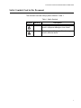
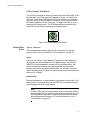
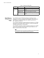
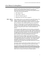
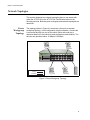
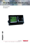
Fast Ethernet Switch AT-FS716L AT-FS724L Installation Guide 613-001151 Rev. B Copyright © 2009 Allied Telesis, Inc. All rights reserved. No part of this publication may be reproduced without prior written permission from Allied Telesis, Inc. Allied Telesis, Alliedware Plus and the Allied Telesis logo are trademarks of Allied Telesis, Incorporated. All other product names, company names, logos or other designations mentioned herein are trademarks or registered trademarks of their respective owners. Allied Telesis, Inc. reserves the right to make changes in specifications and other information contained in this document without prior written notice. The information provided herein is subject to change without notice. In no event shall Allied Telesis, Inc. be liable for any incidental, special, indirect, or consequential damages whatsoever, including but not limited to lost profits, arising out of or related to this manual or the information contained herein, even if Allied Telesis, Inc. has been advised of, known, or should have known, the possibility of such damages. Electrical Safety and Emissions Standards This product meets the following standards. U.S. Federal Communications Commission Radiated Energy Note: This equipment has been tested and found to comply with the limits for a Class A digital device pursuant to Part 15 of FCC Rules. These limits are designed to provide reasonable protection against harmful interference when the equipment is operated in a commercial environment. This equipment generates, uses, and can radiate radio frequency energy and, if not installed and used in accordance with this instruction manual, may cause harmful interference to radio communications. Operation of this equipment in a residential area is likely to cause harmful interference in which case the user will be required to correct the interference at his own expense. Note: Modifications or changes not expressly approved of by the manufacturer or the FCC, can void your right to operate this equipment. Industry Canada This Class A digital apparatus complies with Canadian ICES-003. Cet appareil numérique de la classe A est conforme à la norme NMB-003 du Canada. RFI Emissions FCC Class A, EN55022 Class A, CISPR Class A, CE Warning: In a domestic environment this product may cause radio interference in which case the user may be required to take adequate measures. EMC (Immunity) EN55024 Electrical Safety EN60950-1 (TUV), UL 60950-1 (CULUS), CSA (CULCanada), CD Mark 3 Translated Safety Statements Important: The indicates that a translation of the safety statement is available in a PDF document titled “Translated Safety Statements” (613-000990) posted on the Allied Telesis website at www.alliedtelesis.com. This document is also included with the documentation CD that is shipped with the product. 4 Contents Preface ..................................................................................................................................................................................6 Safety Symbols Used in this Document..................................................................................................................................7 Where to Find Web-based Guides .........................................................................................................................................8 Contacting Allied Telesis ........................................................................................................................................................9 Online Support ................................................................................................................................................................9 Email and Telephone Support .........................................................................................................................................9 Returning Products..........................................................................................................................................................9 For Sales or Corporate Information .................................................................................................................................9 Warranty ..........................................................................................................................................................................9 Management Software Updates ......................................................................................................................................9 Chapter 1: Product Description ........................................................................................................................................10 Overview...............................................................................................................................................................................11 Key Features ........................................................................................................................................................................12 Standards .............................................................................................................................................................................12 Hardware Feature Description..............................................................................................................................................13 ecoFriendly Power Saving Functions ............................................................................................................................13 Twisted-Pair Ports .........................................................................................................................................................14 System and Port LEDs ..................................................................................................................................................15 High Efficiency Internal Power Supply...........................................................................................................................16 A Few Ethernet Switching Basics .........................................................................................................................................17 MAC Address Table ......................................................................................................................................................17 Duplex Mode .................................................................................................................................................................18 Store and Forward.........................................................................................................................................................18 Backpressure and Flow Control ....................................................................................................................................18 Network Topologies ..............................................................................................................................................................20 Power Workgroup Topology ..........................................................................................................................................20 Cascade Topology ........................................................................................................................................................21 Chapter 2: Installation .......................................................................................................................................................22 Reviewing Safety Precautions ..............................................................................................................................................23 Selecting a Site for the Switch ..............................................................................................................................................26 Planning the Installation .......................................................................................................................................................27 Unpacking the Switch ...........................................................................................................................................................28 Installing the Switch on a Table or Desktop..........................................................................................................................29 Installing the Switch in a Rack ..............................................................................................................................................30 Wall-Mounting the Switch .....................................................................................................................................................32 Connecting the Ports and Powering On the Switch..............................................................................................................36 Chapter 3: Troubleshooting ..............................................................................................................................................38 Appendix A: Technical Specifications .............................................................................................................................39 Physical Specifications .........................................................................................................................................................39 Environmental Specifications................................................................................................................................................39 Power Specifications ............................................................................................................................................................39 Safety and Electromagnetic Emissions Certifications...........................................................................................................40 Compliance Standards .........................................................................................................................................................40 RJ-45 Twisted-Pair Port Connectors ....................................................................................................................................40 5 Preface This guide provides the hardware installation instructions for you to install the AT-FS716L or AT-FS724L Fast Ethernet switch. This preface contains the following sections: “Safety Symbols Used in this Document” on page 7 “Where to Find Web-based Guides” on page 8 “Contacting Allied Telesis” on page 9 6 AT-FS716L & AT-FS724L Fast Ethernet Switch Installation Guide Safety Symbols Used in this Document This document uses the safety symbols defined in Table 1. Table 1. Safety Symbols Symbol Meaning Description Caution Performing or omitting a specific action may result in equipment damage or loss of data. Warning Performing or omitting a specific action may result in electrical shock. 7 Preface Where to Find Web-based Guides The installation and user guides for all Allied Telesis products are available in portable document format (PDF) on our web site at www.alliedtelesis.com. You can view the documents online or download them onto a local workstation or server. 8 AT-FS716L & AT-FS724L Fast Ethernet Switch Installation Guide Contacting Allied Telesis This section provides Allied Telesis contact information for technical support as well as sales or corporate information. Online Support You can request technical support online by accessing the Allied Telesis Knowledge Base from the following web site: www.alliedtelesis.com/support. You can use the Knowledge Base to submit questions to our technical support staff and review answers to previously asked questions. Email and Telephone Support For Technical Support via email or telephone, refer to the Allied Telesis web site: www.alliedtelesis.com. Select your country from the list displayed on the website. Then select the appropriate menu tab. Returning Products Products for return or repair must first be assigned a Return Materials Authorization (RMA) number. A product sent to Allied Telesis without a RMA number will be returned to the sender at the sender’s expense. To obtain an RMA number, contact the Allied Telesis Technical Support group at our web site: www.alliedtelesis.com/support/rma. Select your country from the list displayed on the website. Then select the appropriate menu tab. For Sales or Corporate Information Warranty Management Software Updates You can contact Allied Telesis for sales or corporate information at our web site: www.alliedtelesis.com. Select your country from the list displayed on the website. Then select the appropriate menu tab. For warranty information on both the AT-FS716L & AT-FS724L Unmanaged Fast Ethernet Switches, go to www.alliedtelesis.com/ warranty for the specific terms and conditions and for warranty registration. New releases of management software for our managed products are available from either of the following Internet sites: Allied Telesis web site: www.alliedtelesis.com Allied Telesis FTP server: ftp://ftp.alliedtelesis.com If you prefer to download new software from the Allied Telesis FTP server from your workstation’s command prompt, you will need FTP client software and you must log in to the server. Enter “anonymous” for the user name and your email address for the password. 9 Chapter 1 Product Description This chapter contains the follows sections: “Overview” on page 11 “Key Features” on page 12 “Standards” on page 12 “Hardware Feature Description” on page 13 “A Few Ethernet Switching Basics” on page 17 “Network Topologies” on page 20 10 AT-FS716L & AT-FS724L Fast Ethernet Switch Installation Guide Overview The AT-FS716L and AT-FS724L Fast Ethernet Switches provide simple, energy efficient, and cost-effective solutions for switching 10 Mbps and 100 Mbps network traffic. The AT-FS716L and AT-FS724L switches feature 16 and 24 10/100Base-TX twisted-pair ports respectively. Each port has an RJ-45 connector and a maximum operating distance of 100m and is capable of Auto-Negotiating speeds of 10 or 100 Mbps at half/full-duplex operation. Both the AT-FS716L and AT-FS724L Fast Ethernet switches can be used on a desktop, mounted to a wall or in a rack and feature high efficiency, low power consumption internal power supplies. These switches are easy to install and do not require any software configuration or management. Figure 1 and 2 illustrate the front and rear panels of these switches. AT-FS724L 100 LINK 24 Port Unmanaged Fast Ethernet Switch POWER 1 3 5 7 9 11 13 15 17 19 21 23 2 4 6 8 10 12 14 16 18 20 22 24 ACT 10 LINK FDX ACT HDX COL 1 3 5 7 9 11 13 15 17 19 21 23 2 4 6 8 10 12 14 16 18 20 22 24 1540 100-240VAC~ 1541 Figure 1. AT-FS724L Front and Rear Panels AT-FS716L 100 LINK 16 Port Unmanaged Fast Ethernet Switch POWER 1 3 5 7 9 11 13 15 2 4 6 8 10 12 14 16 ACT 10 LINK FDX ACT HDX COL 1 3 5 7 9 11 13 15 2 4 6 8 10 12 14 16 1527 100-240VAC~ Figure 2. AT-FS716L Front and Rear Panels 11 Chapter 1: Product Description Key Features The AT-FS716L and AT-FS724L Fast Ethernet switches have the following key features: 16 each RJ-45 10/100Base-TX ports on the AT-FS716L Switch 24 each RJ-45 10/100Base-TX ports on the AT-FS724L Switch ecoFriendly power saving features including: – Auto-power saving mode on a per-port basis when link is down – Auto-adjusts port power output based on cable length when link is up – Low power mode LED ecoFriendly push button – Highly efficient internal Power supply Quiet, “fanless” operation Auto MDI/MDI-X on all ports Auto-Negotiation on all ports (IEEE 802.3u-compliant) Store and forward switching mode Backpressure and flow control (IEEE 802.3x-compliant) BPDU packet pass through support EAPOL packet pass through support Storage for up to 8K MAC addresses MAC address aging time of 200 to 300 seconds Non-blocking full wire speed System and port LEDs For use on a desktop, wallmount, or rackmount RoHS and China RoHS compliant Standards The AT-FS716L and AT-FS724L Fast Ethernet switches support the following standards: IEEE 802.3 – 10BASE-T standard IEEE 802.3u – 100BASE-TX standard with Auto-negotiation IEEE 802.3x – Flow Control, Symmetric and Asymmetric IEEE 802.3z - Full Duplex 12 AT-FS716L & AT-FS724L Fast Ethernet Switch Installation Guide Hardware Feature Description The hardware features of the AT-FS716L and AT-FS724L Fast Ethernet switches are described in the following sections: ecoFriendly Power Saving Functions “ecoFriendly Power Saving Functions” “Twisted-Pair Ports” on page 14 “System and Port LEDs” on page 15 “High Efficiency Internal Power Supply” on page 16 The AT-FS716L and AT-FS724L implement the following power saving features. Cable Length Power Savings This feature automatically allows the port to use the minimum amount of power required to commnicate with its end node based on the cable length. When an individual port’s link status is UP, the length of the cable connected to the port is automatically detected and the power needed out of the port is adjusted accordingly to minimize power consumption. More power will be used by a port when a longer cable is installed than for a shorter cable. Link Down Power Savings Approximately ten seconds after a port’s link status changes to DOWN, the port will enter into a link down power savings mode. While in this mode, the port will monitor the receive pair for detection of incoming signals such as link pulses and fast link pulses. Once a signal is detected, the port will “wake up” and establish the proper link while resuming normal operation. 13 Chapter 1: Product Description LED ecoFriendly Push Button The LED ecoFriendly push button is located next to the Power LED on the left-hand side of the front panel as illustrated in Figure 3. It enables the LED Low Power Mode (LPM) feature. This mode allows you to conserve power by turning off the port status LEDs when you do not required the LED status indications on the front panel. To toggle the LEDs on or off, press the ecoFriendly button. The LPM feature does not affect the the Power LED or the network operations of the switch ports. POW Figure 3. LED ecoFriendly Push Button Twisted-Pair Ports Type of Connector The twisted-pair ports feature 8-pin RJ-45 connectors. (For the port pinouts, refer to “RJ-45 Twisted-Pair Port Connectors” on page 40. Speed The ports are 10Base-T and 100Base-T compliant and are capable of 10 megabits per second (Mbps) and 100 Mbps speeds. The ports are IEEE 802.3u Auto-Negotiation compliant. With Auto-Negotiation, the switch automatically matches the highest possible common speed between each switch port and each end-node. For example, if an endnode is capable of only 10 Mbps, the switch sets the port connected to the end-node to 10 Mbps. Duplex Mode Each twisted-pair port on these switches can operate in either half- or full duplex mode. The twisted-pair ports are IEEE 802.3u-compliant and will Auto-Negotiate the duplex mode setting. Note In order for the switch to set the duplex mode for each port correctly, the end-nodes that you connect to the switch ports should also use Auto-Negotiation. Otherwise, a duplex mode mismatch can occur, affecting network performance. For further information, refer to “Duplex Mode” on page 18. 14 AT-FS716L & AT-FS724L Fast Ethernet Switch Installation Guide Maximum Distance Each twisted-pair port has a maximum operating distance of 100 m (328 feet). Type of Cabling For 10 Mbps operation, Category 3 or better 100 ohm shielded or unshielded twisted-pair cabling is required. For 100 Mbps operation, Category 5 and Enhanced Category 5 (5E) 100 ohm shielded or unshielded twisted-pair cabling is required. Auto MDI/MDI-X All of the twisted-pair ports on these switches are auto-MDI and IEEE 802.3ab-compatible. When a port's speed and duplex mode are set through Auto-Negotiation, the port uses the auto-MDI feature to automatically configure itself as MDI or MDI-X when connected to an endnode. Consequently, you can use either a straight-through or crossover twisted-pair cable when connecting any network device to a port. System and Port LEDs The system and port LEDs on the front panel of the AT-FS724L switch display the switch and its port status information. Each port has two LEDs. Table 1 describes the system and twisted-pair port LEDs on the ATFS716L and AT-FS724L Fast Ethernet switches. Table 1. System and Port LEDs LED POWER L/A State Description Green The switch is powered ON and operating normally. OFF The switch has no power. Green The port is establishing a valid link at 100 Mbps. Blinking Green The port is receiving/transmitting data at 100 Mbps. Amber The port is establishing a valid link at 10 Mbps. Blinking Amber The port is receiving/transmitting data at 10 Mbps. OFF There is no valid link on the port. 15 Chapter 1: Product Description Table 1. System and Port LEDs LED DPX High Efficiency Internal Power Supply State Description Green The port is establishing at full-duplex mode. Blinking Green Collisions are present on the port. OFF The port is establishing at half-duplex mode. The AT-FS716L and AT-FS724L Fast Ethernet Switches are both designed for low power consumption while operating. They use internal, high efficiency, universal switching power supplies operating from 100 ~ 240V AC at 50/60 Hz. The AT-FS716L switch has a maximum power consumption of 4.6 Watts when the LED ecoFriendly switch is ON and all 16 ports are loaded with 100 MB of network traffic on 100m cables. The AT-FS724L switch has a maximum power consumption of 6.7 Watts with the LED ecoFriendly switch ON and all 24 ports loaded with 100 Mbps of network traffic on 100m cables. Note This maximum power consumption information was measured when the switchs’ AC input voltage was 240 VAC @ 50 Hz. 16 AT-FS716L & AT-FS724L Fast Ethernet Switch Installation Guide A Few Ethernet Switching Basics An Ethernet switch interconnects network devices, such as workstations, printers, routers, and other Ethernet switches, so that they can communicate with each other by sending and receiving Ethernet frames. This is done with the following features: MAC Address Table “MAC Address Table” “Duplex Mode” on page 18 “Store and Forward” on page 18 “Backpressure and Flow Control” on page 18 Every hardware device on your network has a unique MAC address. This address is assigned to the device by the device’s manufacturer. For example, when you install a Network Interface Card (NIC) in a computer the NIC already has a MAC address assigned to it by its manufacturer. Both the AT-FS716L and the AT-FS724L Fast Ethernet switches can contain up to 8,000 entries on its MAC address table. Each switch uses the table to store the MAC addresses of the network end nodes connected to the ports, along with the port number on which each address was learned. A switch learns the MAC addresses of the end-nodes by examining the source address of each packet received on a port. It adds the address and port on which the packet was received to the MAC table if the address had not already been entered in the table. The result is that a table contains all the MAC addresses of the devices that are connected to the switch’s ports, and the port number where each address was learned. When the switch receives a packet, it also examines the destination address and, by referring to its MAC address table, determines the port on which the destination end-node is connected. Then it forwards the packet to the appropriate port and on to the end-node. This increases network bandwidth by limiting each frame to the appropriate port where the intended end-node is located, freeing the other switch ports for receiving and transmitting data. If the switch receives a packet with a destination address that is not in the MAC address table, it floods the packet to all the ports on the switch. If the switch receives a packet with a destination address that is on the same port on which the packet was received, it discards the packet without forwarding it on to another port. Since both the source end-node and the destination end-node for the packet are located on the same port on the switch, there is no reason for the switch to forward the packet. 17 Chapter 1: Product Description Duplex Mode Duplex mode refers to how an end-node receives and transmits data. If an end-node can receive or transmit data, but not both simultaneously, it is operating in a half-duplex mode. If an end-node can receive and transmit data simultaneously, the end-node is said to be operating in full-duplex mode. Naturally, an end-node capable of operating in full-duplex can handle data much faster than an end-node that can only operate in halfduplex mode. The twisted-pair ports on the AT-716L and AT-FS724L Fast Ethernet switches can operate in either half-or full-duplex mode. They are IEEE 802.3u-compliant and use Auto-Negotiation to set the duplex mode setting for you automatically. Note For Auto-Negotiation to operate properly on a switch, the end-nodes connected to the switch should also use Auto-Negotiation. If an endnode does not have this feature and has a fixed duplex mode of fullduplex, the result will be a duplex mode mismatch between the endnode and a switch port. A port on the switch connected to an endnode with a fixed duplex mode of full-duplex will operate at only halfduplex. This results in the end node using full-duplex and the switch port using half-duplex. This can produce network performance problems. Should you encounter this situation, you must configure the port on the end-node to use Auto-Negotiation or, if it lacks that feature, to half-duplex. Store and Forward Both switches use store and forward as the method for receiving and transmitting frames. When a Ethernet frame is received on a switch port, the switch does not retransmit the frame out the destination port until it has received the entire frame and stored the frame in a port buffer. Then it examines the frame to determine if it is a valid frame. Invalid frames, such as fragments or runts, are discarded by the switch. This insures that only valid frames are transmitted out the switch ports and that damaged frames are not propagated on your network. Backpressure and Flow Control To maintain the orderly movement of data between the end-nodes, an Ethernet switch may periodically need to signal an end-node to stop sending data. This can occur under several circumstances. For example, if two end-nodes are operating at different speeds, the switch, while transferring data between the end-nodes, might need to instruct the faster end-node to stop transmitting data allowing the slower end-node to catch up. An example of this would be when a server operating at 100 Mbps is sending data to a workstation operating at only 10 Mbps. 18 AT-FS716L & AT-FS724L Fast Ethernet Switch Installation Guide How a switch signals an end-node to stop transmitting data differs depending on the duplex mode of the end-node and switch port. A twisted-pair port operating in half-duplex mode stops an end-node from transmitting data by forcing a collision. A collision on an Ethernet network occurs when two end-nodes attempt to transmit data using the same data link at the same time. A collision causes an end-node to stop sending data, wait for a brief period of time, and then retransmit the same data. Once the switch is ready to receive data again, the switch stops forcing collisions. This is referred to as backpressure. A port operating in full-duplex mode uses PAUSE frames, as specified in the IEEE 802.3x standard, to stop the transmission of data from an endnode. Whenever the switch wants an end-node to stop transmitting data, it issues this frame. The frame instructs the end-node to cease transmission for a period of time specified within the frame. The switch continues to issue PAUSE frames until it is ready again to receive data from the endnode. This is referred to as flow control. 19 Chapter 1: Product Description Network Topologies This section illustrates two network topologies that you can create with either the AT-FS716L or the AT-FS724L Fast Ethernet switch in the following sections. Both the power workgroup and cascade topologies are described. Power Workgroup Topology The topology shown in Figure 4 is commonly referred to as a power workgroup topology. In this configuration, each workstation, or end-node is connected directly to a port on the switch. Each end-node has a dedicated data link to the switch for best performance and reliability. The devices can operate at either 10 Mbps or 100 Mbps. AT-FS716L 100 LINK 16 Port Unmanaged Fast Ethernet Switch 1 3 5 7 9 11 13 15 POWER 2 4 6 8 10 12 14 16 ACT 10 LINK FDX ACT HDX COL 1 3 5 7 9 11 13 2 4 6 8 10 12 14 15 16 1539 10 Mbps 100 Mbps Figure 4. Power Workgroup Topology 20 AT-FS716L & AT-FS724L Fast Ethernet Switch Installation Guide Cascade Topology Connecting two similar networking devices together is called “cascading.” Figure 5 illustrates this topology where Port 19 on the AT-FS724L switch is connected to Port 16 on the AT-FS716 switch. Since the ports are configured as auto MDI/MDI-X, a crossover or straight-through Category 5 or better twisted-pair cable can be used in any of the ports. AT-FS716L 100 LINK 16 Port Unmanaged Fast Ethernet Switch 1 3 5 7 9 11 13 15 POWER 2 4 6 8 10 12 14 16 AT-FS724L 1 3 5 7 9 11 13 15 17 19 21 23 2 4 6 8 10 12 14 16 18 20 22 24 10 LINK FDX ACT HDX COL 3 5 7 9 11 13 15 2 4 6 8 10 12 14 16 100 LINK 24 Port Unmanaged Fast Ethernet Switch POWER ACT 1 ACT 10 LINK FDX ACT HDX COL 1 3 5 7 9 11 13 15 17 19 21 2 4 6 8 10 12 14 16 18 20 22 23 24 1538 10 Mbps 100 Mbps Figure 5. Cascade Topology 21 Chapter 2 Installation This chapter contains the following sections: “Reviewing Safety Precautions” on page 23 “Selecting a Site for the Switch” on page 26 “Planning the Installation” on page 27 “Unpacking the Switch” on page 28 “Installing the Switch on a Table or Desktop” on page 29 “Installing the Switch in a Rack” on page 30 “Wall-Mounting the Switch” on page 32 “Connecting the Ports and Powering On the Switch” on page 36 22 AT-FS716L & AT-FS724L Fast Ethernet Switch Installation Guide Reviewing Safety Precautions Please review the following safety precautions before you begin to install the switch or any of its components. Note The indicates that a translation of the safety statement is available in a PDF document titled “Translated Safety Statements” (613-000990) posted on the Allied Telesis website at www.alliedtelesis.com. This document is also included with the CD that is shipped with the product. Warning To prevent electric shock, do not remove the cover. No userserviceable parts inside. This unit contains hazardous voltages and should only be opened by a trained and qualified technician. To avoid the possibility of electric shock, disconnect electric power to the product before connecting or disconnecting the LAN cables. E1 Warning Do not work on equipment or cables during periods of lightning activity. E2 Warning To prevent electric shock, do not remove the cover. No userserviceable parts inside. This unit contains hazardous voltages and should only be opened by a trained and qualified technician. To avoid the possibility of electric shock, disconnect electric power to the product before connecting/disconnecting the LAN cables. E3 Warning Do not work on equipment or cables during periods of lightning activity. E4 Warning Power cord is used as a disconnection device. To de-energize equipment, disconnect the power cord. E5 23 Chapter 2: Installation Warning Class I Equipment. This equipment must be earthed. The power plug must be connected to a properly wired earth ground socket outlet. An improperly wired socket outlet could place hazardous voltages on accessible metal parts. E6 Caution Pluggable Equipment: The socket outlet shall be installed near the equipment and shall be easily accessible. E7 Caution Air vents: Air vents must not be blocked and must have free access to the room ambient air for cooling. E8 Caution Operating Temperature: This product is designed for a maximum ambient temperature of 40°C. E9 Caution All Countries: Install this product in accordance with local and National Electric Codes. E10 Circuit Overloading: Consideration should be given to the connection of the equipment to the supply circuit and the effect that overloading of circuits might have on overcurrent protection and supply wiring. Appropriate consideration of equipment nameplate ratings should be used when addressing this concern. E21 Warning Mounting of the equipment in the rack should be such that a hazardous condition is not created due to uneven mechanical loading. E25 24 AT-FS716L & AT-FS724L Fast Ethernet Switch Installation Guide If installed in a closed or multi-unit rack assembly, the operating ambient temperature of the rack environment may be greater than the room ambient temperature. Therefore, consideration should be given to installing the equipment in an environment compatible with the manufacturer’s maximum rated ambient temperature (Tmra). E35 Caution Installation of the equipment in a rack should be such that the amount of air flow required for safe operation of the equipment is not compromised. E36 Warning Reliable earthing of rack-mounted equipment should be maintained. Particular attention should be given to supply connections other than direct connections to the branch circuits (e.g., use of power strips). E37 25 Chapter 2: Installation Selecting a Site for the Switch Observe the following requirements when choosing a site for the AT-FS716L or AT-FS724L Fast Ethernet Switches: If you plan to install the switch in an equipment rack, be sure that the rack is safely secured and that it will not tip over. Devices in a rack should be installed starting at the bottom, with the heavier devices near the bottom of the rack. If you are installing the switch on a table, be sure that the table is level and secure. The power outlet for the switch should be located near the unit and should be easily accessible. The site should provide for easy access to the ports on the front of the switch. This will make it easy for you to connect and disconnect cables, as well as view the switch’s LEDs. To allow proper cooling of the switch, air flow around the unit and through its vents on the side and rear should not be restricted. Do not place objects on top of the switch. Do not expose the switch to moisture or water. Ensure that the site is a dust-free environment. You should use dedicated power circuits or power conditioners to supply reliable electrical power to the network devices. 26 AT-FS716L & AT-FS724L Fast Ethernet Switch Installation Guide Planning the Installation Be sure to observe the following guidelines when planning the installation of your switch. The end-nodes connected to the twisted-pair port can be operated at either 10 Mbps or 100 Mbps and half- or full-duplex mode. The end-node connected to a port on the switch can be a network adapter card, repeater, router, hub, or another switch. Table 2 contains the cabling specifications for the twisted-pair ports. Table 2. Ttwisted-pairwisted-pair Cabling and Distances Speed Type of Cable Maximum Operating Distance 10 Mbps Category 3 or better 100-ohm shielded or unshielded twisted-pair cable 100 m (328 ft) 100 Mbps Category 5 or Category 5E (Enhanced) 100-ohm shielded or unshielded twisted-pair cable 100 m (328 ft) Note The twisted-pair ports on the switch feature Auto-MDI when operating at either 10 or 100 Mbps. Each port is individually configured as MDI or MDI-X when connected to an end-node. Consequently, you can use either a straight-through or crossover twisted-pair cable when connecting any network device to a twisted-pairport on the switch. A port operating at 10 or 100 Mbps uses two of the pairs in the twisted-pair twisted-pairwiring. 27 Chapter 2: Installation Unpacking the Switch To unpack an AT-FS716L or an AT-FS724L switch, perform the following procedure: 1. Remove all components from the shipping package. Note Store the packaging material in a safe location. You must use the original shipping material if you need to return the unit to Allied Telesyn. 2. Place the switch on a level, secure surface. 3. Ensure the following hardware components are included in your switch package. If any item is missing or damaged, contact your Allied Telesis sales representative for assistance. One AT-716L or AT-FS724L Fast Ethernet Switch Four self-adhesive rubber feet Wall mount kit 19” rack mounting kit AC power cord 28 AT-FS716L & AT-FS724L Fast Ethernet Switch Installation Guide Installing the Switch on a Table or Desktop To install the switch on a table or desktop, perform the following procedure: 1. Remove all the items from the packaging and store the packaging material in a safe place. In the event a problem occurs and you need to return the unit, please use as much of the original shipping material as possible. 2. Attach the four self-adhesive rubber feet to the bottom of the switch, as shown in Figure 6. 4 POWER 2 3 1 6 5 8 7 10 9 14 12 13 11 16 Port Unmanaged Fast Ethernet Switch AT-FS716L 16 2 4 6 8 10 12 14 16 15 1 3 5 100 LINK 7 ACT 10 LINK 9 ACT 11 FDX HDX 13 15 COL 1529 Figure 6. Attaching the Rubber Feet 3. Turn the switch over and place it on a flat and secure surface, leaving ample space around the switch for ventilation. 4. The switch is now ready for cabling and powering up. Go to “Connecting the Ports and Powering On the Switch” on page 36 to connect your switch to the network. 29 Chapter 2: Installation Installing the Switch in a Rack Perform the following procedure to install either switch in a standard 19-inch rack. Two rack mounting brackets and eight mounting screws are provided for attachment to your switch. 1. Remove any data cables and the power cord from the switch if they are attached to the switch. 2. If attached, remove the rubber feet from the bottom of the chassis with a flat bladed screw driver as shown in Figure 7. Figure 7. Removing the Rubber Feet from Chassis 3. Attach the two mounting brackets (provided) to the sides of the switch using the bracketmounting screws (provided), as shown in Figure 8. 24 Por t Unm anaged 1 POWE R 2 Fast Eth 3 4 ernet 5 AT-F S724 Switch 7 9 L 11 13 15 17 19 21 23 1 3 6 8 10 5 12 14 16 7 18 20 100 22 LINK 9 24 ACT 10 LINK 11 2 ACT 13 FDX HDX 4 15 COL 6 17 8 19 10 21 12 23 14 16 18 20 22 24 1546 Figure 8. Attaching Brackets for Rackmounting 30 AT-FS716L & AT-FS724L Fast Ethernet Switch Installation Guide Warning The chassis may be heavy and awkward to lift. Allied Telesis recommends that you get assistance when mounting the chassis in an equipment rack. 30 4. Mount the switch in the 19-inch rack using the rackmounting screws (not provided), as shown in Figure 9. 17 19 21 23 18 20 22 24 1547 Figure 9. Rackmounting the Switch 5. The switch is now ready for cabling and powering up. Go to “Connecting the Ports and Powering On the Switch” on page 36 to connect your switch to the network. 31 Chapter 2: Installation Wall-Mounting the Switch Either switch can be mounted horizontally on a wall using the wallmounting brackets that come with the unit. The wall-mounting screws and plastic anchors necessary to mount the switch on a wall are provided. To wall-mount the switch, perform the following procedure: 1. Remove any data cables and the power cord from the switch if they are attached to the switch. 2. If attached, remove the rubber feet from the bottom of the chassis with a flat bladed screw driver as shown in Figure 10. Figure 10. Removing the Rubber Feet from Chassis 3. Select a wall location for the switch. 32 AT-FS716L & AT-FS724L Fast Ethernet Switch Installation Guide 13 0. 17 m m (5 1/ 8 in ) 4. Install the two plastic anchors and two screws provided into the wall so that they are level with each other. They should spaced 130.17mm (5 1/8 in) apart for the AT-FS716L or 200mm (7 7/8 in) apart for the ATFS724L as shown in Figure 11 and Figure 12. 1553 Figure 11. Installing the Mounting Screws for AT-FS716L in the Wall 33 Chapter 2: Installation n) /8 i 77 m( m 200 1554 Figure 12. Installing the Mounting Screws for AT-FS724L in the Wall 5. Mount the chassis on the wall by sliding the chassis over the mounting screws You may mount the switch as shown in Figure 13 with the ports pointing up or you may elect to mount the switch 180 degrees from what is shown with the switch ports pointing down. 34 AT-FS716L & AT-FS724L Fast Ethernet Switch Installation Guide PO W ER 2 4 16 Po rt 6 10 3 5 Fa st Eth er ne tS w itc h 7 12 U nm an ag ed 1 8 14 16 9 13 A TFS 11 2 71 6L 15 4 1 6 3 8 0 LIN 5 K 10 10 AC T 1 7 0L IN 12 K T 9 AC 14 FD X 11 HD X 16 C O L 13 15 1533 Figure 13. Mounting the Switch on the Wall 6. The switch is now ready for cabling and powering up. Go to “Connecting the Ports and Powering On the Switch” on page 36 to connect your switch to the network. 35 Chapter 2: Installation Connecting the Ports and Powering On the Switch To connect to the ports on the switch, perform the following procedure: 1. Connect the twisted-pair data cables to the RJ-45 ports on the switch, as shown in Figure 14. 1 3 100 LIN 5 K ACT 10 L INK 7 ACT 9 FDX HD 11 X 2 CO L 13 4 15 6 8 10 12 14 16 1530 Figure 14. Connecting the Twisted-twisted-pairPair Data Cables When connecting a twisted-pair cable to a port, observe the following guidelines: An RJ-45 connector should fit snugly into the port on the switch. The tab on the connector should lock the connector into place. The ports on the switch are auto-MDI/MDI-X. You can use either a straight-through or crossover twisted-pair cable to connect any type of network device to a port on the switch. The network should not contain data loops, which can adversely affect network performance. A data loop exists when two or more network devices can communicate with each other over more than one data path. 36 AT-FS716L & AT-FS724L Fast Ethernet Switch Installation Guide 2. Apply AC power to the switch by plugging the power cord into the AC power connector on the back panel of the unit, as shown in Figure 15. 100-2 40VA C~ 1535 Figure 15. Connecting the AC Power Connector to Switch Warning Power cord is used as a disconnection device: To de-energize equipment, disconnect the power cord. 5 3. Plug the other end or the power cord into a wall outlet. 4. Verify that the POWER LED is green. If the LED is OFF, refer to “Troubleshooting” on page 38. The switch is ready for network operations. 37 Chapter 3 Troubleshooting This chapter contains information on how to troubleshoot the switch in the event that a problem occurs. Note If you are still unable to resolve the problem after following the instructions in this chapter, contact ATI Technical Support for assistance. Refer to “Contacting Allied Telesis” on page 9. Check the POWER LED on the front of the switch. If the LED is OFF, indicating that the unit is not receiving power, do the following: Ensure that the power cord is securely connected to a power outlet and that the other end of the power cord is securely connected to the back of the switch. Verify that the power outlet has power by connecting another device to it. Try connecting the unit to another power source. Try using a different power cord. Verify that the voltage from the power source is within the required levels for your region. Verify that the LNK/ACT LED for each port is ON. If a LNK/ACT LED is OFF, do the following: Verify that the ecoFriendly switch is OFF - switch is not depressed. If it is ON (depressed), the LNK/ACT LEDs will not be ON or active. Verify that the end-node connected to the port is powered ON and is operating properly. Verify that the twisted-pair cable is securely connected to the port on the switch and to the port on the end-node. Ensure that the twisted-pair cable does not exceed 100 meters (328 feet). Verify that you are using the appropriate category of twisted-pair cable: Category 3 or better for 10 Mbps operation and Category 5 and Category 5E for 100 Mbps operation. 38 Appendix A Technical Specifications Physical Specifications Dimensions: AT-FS716L AT-FS724L Weight: AT-FS716L AT-FS724L (W x D x H) 184 mm x 124 mm x 44 mm (7.24 in x 4.88 in x 1.73 in) 280 mm x 180mm x 44 mm (11.02 in x 7.08 in x 1.73 in) .800 kg (1.76 lbs) 1.592 kg (3.51 lbs) Environmental Specifications Operating Temperature: 0° C to 40° C (32° F to 104° F) Storage Temperature: -25° C to 70° C (-13° F to 158° F) Operating Humidity: 5% to 90% non-condensing Storage Humidity: 5% to 95% non-condensing Operating Altitude Range: Up to 4,000m (13,000 feet) Power Specifications Maximum Power Consumption: (AC side 240 VAC 50 Hz with 100m cables on all ports) AT-FS716L with ecoFriendly switch ON 4.6 W @100Mbps AT-FS724L with ecoFriendly switch ON 6.7 W @100Mbps AC Input Electrical Ratings: 100~240V AC Frequency: 50/60 Hz, 0.5A input 39 Appendix A: Technical Specifications Safety and Electromagnetic Emissions Certifications RFI Emissions FCC Class A, EN55022 Class A, CISPR 22 Class A Safety UL- USA, LVD (EN60950), CSA or cUL - Canada, CE Immunity EN55024 Electrical Safety UL 60950-1 (CULUS), EN60950 (TUV) Compliance Standards IEEE 802.3 – Ethernet IEEE 802.3u – Fast Ethernet IEEE 802.3x – Flow Control, Symmetric and Asymmetric IEEE 802.3z - Full Duplex RJ-45 Twisted-Pair Port Connectors This section lists the connectors and connector pinouts for the AT-FS716L and AT-FS724L Fast Ethernet Switches ports. Figure 16 illustrates the pin layout to an RJ-45 connector and port. 1 8 8 1 Figure 16. RJ-45 Connector and Port Pin Layout 40 AT-FS716L & AT-FS724L Fast Ethernet Switch Installation Guide Table 3 lists the RJ-45 pin signals when a twisted-pair port is operating in the MDI configuration. Table 3. MDI Pin Signals (10Base-T or 100Base-TX) Pin Signal 1 TX+ 2 TX- 3 RX+ 6 RX- Table 4 lists the RJ-45 port pin signals when a twisted-pair port is operating in the MDI-X configuration. Table 4. MDI-X Pin Signals (10Base-T or 100Base-TX) Pin Signal 1 RX+ 2 RX- 3 TX+ 6 TX- 41