1
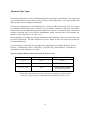
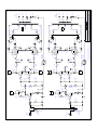
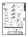
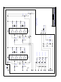
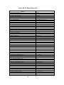
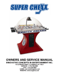
Stereo 160
Vacuum Tube Amplifier
Owner's Manual
TRIODE
POWER ON
ULTRALINEAR
POWER OFF
R
OUTPUT TUBE BIAS ADJUSTMENT
ON
LEFT CHANNEL
V3
V4
RIGHT CHANNEL
V7
STEREO 160
Vacuum Tube Power Amplifier
V8
BIAS DISPLAY
OFF
Stereo 160 Vacuum Tube Power Amplifier
Contents
Introduction ........................................................................ 3
Vacuum Tube Warm Up .................................................... 4
Rear Panel Inputs and Outputs ........................................... 4
Input Sensitivity Setting ..................................................... 5
Power On/Off Indicators and Fuses .................................... 6
Triode/Ultralinear Modes ................................................... 7
Bias Adjustments - general ................................................. 8
Output Tube Bias Adjustment Procedure ........................... 9
Burn-In Procedure for New Output Tubes ......................... 10
Tube Replacement .............................................................. 11
Alternate Tube Types ......................................................... 13
Minimizing Noise in the System ........................................ 14
Warranty ............................................................................. 15
Stereo 160 Specifications ................................................... 16
Schematics .......................................................................... 17
Stereo 160 PC Board Parts List .......................................... 20
Please read this manual thoroughly before operating your new Stereo 160.
Introduction
Congratulations on your purchase of the Dynaco Stereo 160 Amplifier. This product
was designed to provide the highest combination of quality and value available, which
is the Dynaco tradition.
The Dynaco Stereo 160 amplifier uses special power supply buffering circuitry - found
in no other brand of amplifiers in this class. We have included a separate buffer circuit
for each of the input and driver tubes in the Stereo 160, allowing each amplification
stage to function more independently, (as if each one had its own separate power
supply). This method contributes significantly to the sonic clarity of the Stereo 160.
The Stereo 160 can be operated in either Triode or Ultralinear mode.
between the two is easily done via a front panel switch.
Switching
State-of-the-art biasing circuitry allows you to easily attain precision bias settings for
each of the output tubes through front panel adjustments and indicators.
Another special feature of the Stereo 160 is its adjustable Input Sensitivity. This allows
the Stereo 160 to be connected directly to components having vastly different output
signal levels. The user can, for example, connect a CD player directly to the Stereo 160
without using a preamplifier.
You will find the Stereo 160 sounds better than the large majority of other amplifiers both solid state and vacuum tube designs - regardless of price. Your Stereo 160 was
designed and built entirely in the USA. We are proud to offer this outstanding amplifier
to discerning audiophiles the world over.
Dynaco Engineering Group
Vacuum Tube Warm-Up
Although a vacuum tube power amplifier begins to work in as little as 15 seconds after being switched on,
it is important to allow a 3 minute warm-up period before using the amplifier.
Output tubes can be slightly damaged each time they are forced into use before being warmed-up,
resulting in non-optimum sound and shorter tube life. If one listens to music during the warm-up period,
one may notice that the output volume of the amplifier changes as the tubes warm up.
We recommend that you wait at least 3 minutes after switching the amplifier on before using it. On the
Stereo 160, waiting about one minute after the four bias lamps turn from “green” to “off” is a proper
(minimum) warm-up period.
(See section entitled Bias Adjustments - general)
Rear Panel Inputs and Outputs
Inputs
There are two input jacks located on the rear panel of the amplifier - labeled Left and Right. These
connect to your preamplifier Line Outputs.
Never plug in, or disconnect, interconnect cables from other components to the
amplifier when it is turned on. To do so could cause a fuse to blow or even damage the
speakers.
Outputs
Match the impedance of your speakers to the amplifier by connecting the positive (+) speaker wire of
each channel to its corresponding 2 ohm, 4 ohm, or 8 ohm red binding post. Connect the negative (-)
speaker wire from each channel to its corresponding black binding post.
You can safely connect or disconnect speaker cables to/from the amplifier while it is turned on. It is best
at those times to turn down volume control(s) on any equipment connected to the amplifier inputs.
(Nevertheless, care should be taken to not touch bare speaker wires together if one end of the speaker
cable is connected to the amplifier.)
4
Input Sensitivity Setting
The Input Sensitivity adjustment is located on the rear panel, to the right of the input RCA jacks. This
feature allows you to select how large of an input signal will result in full power output of the amplifier.
The Input Sensitivity adjustment can be used to “match” the Stereo 160 inputs to your preamplifier
outputs. You can set it so that the preamplifier volume control can be turned all the way up before
clipping occurs in the Stereo 160. This also allows you to connect audio components, such as CD
players, directly to the Stereo 160 without using a preamplifier, if desired.
Most power amplifiers have input sensitivities in the range of 1 to 1.5 volts. If an amplifier has an input
sensitivity of 1 volt, this means that an input signal level of 1 volt will produce the full rated output power
of the amplifier.
The Input Sensitivity on the Stereo 160 can be adjusted as follows:
Set at Normal (12 o’clock) the input sensitivity is approximately 1.5V.
Set at Low (9 o’clock) the input sensitivity is approximately 5.5V.
Set at High (3 o’clock) the input sensitivity is approximately .5V.
Set fully clockwise, the input sensitivity is under .3V.
5
Power On/Off Indicators and Fuse
The Stereo 160 Power On/Off indicator is either the Ultralinear (red) lamp or the Triode (amber) lamp.
The lamp which is lit when the Power On/Off switch is turned on will depend upon the Triode/Ultralinear
switch position.
During the first minute or so after the Stereo 160 is first switched on, all four output tube bias indicator
lamps glow green. As the unit warms up, these lamps should go off, indicating the unit is ready for use.
If the bias indicator lamps remain green (or turn red) after the initial warm-up period, a low or high AC
line voltage condition may be indicated. The AC line voltage varies from country to country, city to city,
house to house, and even the time of day in many locations. It can also be affected by common
appliances such as electric heaters, microwave ovens, clothes dryers, etc. Therefore, you may need to set
the output tube bias adjustments to suit your own location. (See section entitled Bias Adjustments general.)
Fuses
AC Line Fuse (F1):
10 Amp Fast-Blow - 100 or 120VAC
5 Amp Fast-Blow - 220 or 240VAC
120
To remove the AC line fuse, use a small screwdriver to
push forward the tab near the center of the Power
Entry Module.
PUSH TAB TO RELEASE FUSE HOLDER
Output Protection (F2, F3):
1/2 Amp Fast-Blow (regardless of line voltage)
F2 (left channel) and F3 (right channel) protect the Output Transformers from damage due to a possible
shorted output tube. If either output tube in one channel shorts, the fuse for that channel will blow.
Although shorted output tubes should be considered rare, the fuse elements themselves become brittle
with age and sometimes fail under normal use. Always keep spare fuses for your Stereo 160 at hand.
Always remove the power cord when accessing the AC line fuse.
6
Triode/Ultralinear Modes
The Ultralinear mode is usually considered to be the “normal” mode of operation. The overall power
rating of the amplifier is specified for Ultralinear mode.
In Ultralinear mode, the screen grid of each output tube is connected to a tap on its associated output
transformer. When Triode mode is selected, the screen grids are (instead) connected to the plates of their
respective output tubes.
Operating the amplifier in Triode mode reduces the amplifier output power to about 1/2 of that in
Ultralinear mode. Triode mode also softens the clipping characteristics of the amplifier so it seems to
need less output power. Triode mode produces more lower-even order harmonics, whereas Ultralinear
mode produces higher-odd order harmonics.
Some people prefer Triode mode; some people prefer Ultralinear mode. The choice of which mode to use
is also often influenced by the sonic characteristics of the speakers being used.
You can listen and compare to determine which mode sounds best to you for your chosen music material
and speakers.
7
Bias Adjustments - general
The Stereo 160 incorporates integrated circuits that monitor the actual quiescent (idle) current of each
output tube. For each output tube there is a separate bias adjustment potentiometer accessible from the
front panel of the amplifier. Directly above each adjustment potentiometer is the indicator lamp for the
tube which it adjusts.
The front panel switch labeled Bias Display On/Off must be ON for bias adjustments. The Bias Display
On/Off switch (optionally) can be left on while listening to music. If it is left on there will be a “lightshow” display effect which varies with the music material.
During bias adjustments each indicator lamp shows three different conditions. When it glows green it
means that the bias is set too low for the output tube. When it glows red it means that the bias is set too
high. When the lamp is not lit (neither green nor red) it means that the bias setting is correct and is in the
range of 87 to 114 millivolts, (measured across each 2 ohm output tube current sensing resistor - R20, 21,
120, or 121). The correct bias current setting for the 6550 output tubes used with the Stereo 160 is:
50ma +/- 5ma
Before bias adjustments are made, the amplifier must be fully warmed up. As a minimum requirement,
the amplifier should be turned on for 15 minutes prior to bias adjustments. Letting it idle for a full hour
so that all components come up to full thermal equalization is also a good idea, but not usually required.
Notes: For newly installed output tubes, the first three hours is the “burn-in” period. During this time
bias settings need to be closely monitored because they go higher (by themselves) while the tubes
burn-in. If a tube is operated with its bias setting a lot higher than it should be, the tube could
actually burn out or cause other amplifier components to fail.
The output tubes in your new Stereo 160 have already been burned-in and properly biased at the
factory. Nevertheless, when you first start using your amplifier you should check the bias
settings using the Output Tube Bias Adjustment Procedure on the following page.
As mentioned earlier, AC line voltage levels can vary greatly. Even after proper output tube bias
adjustments are completed on your amplifier, temporary changes in the AC line voltage can make it seem
that the bias settings are not correct. If the AC line voltage is low, one or more of the bias indicator lamps
may continue to glow green after the initial one-minute warm-up period. Likewise, if one or more of the
bias indicator lamps glows red after the initial warm-up period, a high AC line voltage condition may be
indicated. If a low or high AC line voltage condition is only temporary, you do not need to re-adjust the
bias settings.
8
Output Tube Bias Adjustment Procedure
1) Warm up amplifier for 15 minutes (or more).
2) Turn off any equipment connected to the amplifier inputs and ensure that the Bias Display On/Off
switch is ON.
3) Using the adjustment tool provided with the amplifier, adjust each 25-turn trimmer potentiometer
to a point where its lamp does not glow. (This point should be midway between red and green.)
Counter-clockwise rotation turns the bias down, “towards green”.
Clockwise rotation turns the bias up, “towards red”.
Notes: If the lamp is glowing red it means that the bias is set too high. Do not turn the adjustment
potentiometer further clockwise as this makes the bias setting even higher.
If an output tube bias indicator lamp cannot be adjusted for both green and red, the associated
output tube is probably faulty.
Adjusting the potentiometer for one lamp can seem to affect the lamps of the other tubes as well.
This is normal. Allow each change to settle for a second or two before going on to the next
trimmer potentiometer. Repeat the adjustments as necessary.
Bias adjustments will be needed less often as the output tubes age.
Bias adjustments can be made at any time while using the amplifier - as long as the amplifier is
warmed up.
If the Bias Display On/Off switch is left on, one can easily check the bias settings at a glance.
This could be whenever the amp is not receiving input signals (such as during the blank time
between tracks on a CD or record).
9
Burn-In Procedure for New Output Tubes
Note:
This procedure applies only when you have installed new output tubes which have not yet been
burned-in. (The tubes installed on your new Stereo 160 have already been burned-in at the
factory.) Also see section entitled: Tube Replacement.
1) Turn off any equipment connected to the amplifier inputs.
2) Turn the bias adjust potentiometer for each newly installed tube fully counter-clockwise. This can
take as many as 30 turns. A faint “clicking” sound, which is not harmful, may be heard if you
continue to turn the potentiometer beyond its fully counter-clockwise position. (Use the
adjustment tool provided with the amplifier.)
3) Switch the amplifier on and allow it to warm up 5 to 10 minutes. Ensure that the Bias Display
On/Off switch is set to ON. Note that all bias indicator lamps adjusted in 2) glow green. If any
bias adjustment lamp is not glowing green, ensure that its bias adjustment potentiometer is turned
fully counter-clockwise.
Note:
If an output tube indicator lamp cannot be adjusted for both green and red, the associated output
tube is probably faulty.
4) Adjust the bias potentiometer for each newly installed tube as follows:
a) Turn the potentiometer clockwise to a point where its lamp goes off (glows neither red
nor green.)
b) Slowly turn the potentiometer counter-clockwise, again, to the point where its lamp just
begins to glow fully green again. Repeat this step for each lamp as necessary until all
four are glowing green.
5) After 10 minutes check the indicator lamps to see that they are still glowing green. For any lamp
not glowing green, slowly turn its potentiometer counter-clockwise only until it glows green
again.
6) Check every 30-45 minutes to ensure that the indicator lamps are still glowing green and adjust
them if necessary.
7) After three hours, adjust each bias potentiometer to a position where its lamp does not glow
(midway between red and green).
This completes the burn-in procedure for new output tubes. As future bias adjustments become
necessary, use the Output Tube Bias Adjustment Procedure on page 9.
10
Tube Replacement
CAUTION:
Before replacing tubes on your Stereo 160 ensure the AC power cord is un- plugged from
its AC (wall) outlet (or that the AC power cord is unplugged from the back of the unit) and
wait for three minutes to allow the high voltage power supply to discharge. Gloves may be
worn when changing tubes. Never touch live circuit elements in vacuum tube equipment
because lethal voltages are present when these are turned on.
Note: There are no user serviceable parts inside the Stereo 160 chassis. If a problem arises other than
normal periodic tube replacement, refer to your dealer or a qualified technician.
The most common type of problem in tube equipment is excessive noise caused by a worn or faulty tube.
The characteristics of this noise can vary a great deal, such as: “excessive hiss,” “sputtering,” “rustling
noises,” etc. If a noise problem occurs with your Stereo 160, 99% of the time it will be due to a faulty
tube. Vacuum tube equipment owners become familiar with tube noises and usually become less alarmed
by them as time goes on.
Microphonics (various "pinging" or "howling" sounds) is due to a tube being overly sensitive to physical
vibrations. To avoid this, do not operate vacuum tube equipment on top of vibrating surfaces (such as
loudspeakers). But, if a tube is so sensitive that just having the amplifier turned on causes the
microphonic sounds, the tube will have to be replaced. It can happen that a tube becomes microphonic
with age or that it is only microphonic before it warms up (or only after it warms up).
Because it is possible for oxidation to build up on vacuum tube pins, it is a good idea to remove and clean
them with a small (brass bristle) wire brush once a year. At this time it is also recommended to clean the
tube pins with contact cleaner. Contact cleaner leaves a thin coating on the pins which helps prevent
oxidation. The contact cleaner can either be sprayed directly onto the tube pins (don’t get any on the
glass part of the tube) or can be sprayed on a clean cloth which is then used to wipe the tube pins.
Note:
When removing a tube, grasp the tube socket with one hand and the tube with the other hand.
Move the tube (slightly) from side to side while pulling upward.
An easy way to determine if a tube in any particular position is causing undesirable
noise is to swap the suspected tube with its counterpart in the opposite channel. If
the noise jumps to the other channel, the tube you suspected is indeed faulty.
The most certain method for confirming a faulty tube is by substitution of a known
good tube.
11
Tube Replacement (cont.)
Input and Driver Tubes
The input and driver tubes in your Stereo 160 could provide 5,000 to 10,000 hours of use. They will
probably outlast the output tubes by a factor of 2:1. We recommend that the input and driver tubes be
replaced after no more than 3,000 to 4,000 hours of use to avoid the slightly "muffled" sound or slight
bass "roll-off" which can begin to occur with old tubes. This replacement interval is equivalent to about 2
1/2 years when the amplifier is used 4 hours per day (or 5 years when used 2 hours per day).
The most likely source of tube noise in the Stereo 160 is the 12AT7 input tube - V1 (left channel) or V5
(right channel).
Output Tubes
You should expect the 6550s in the Stereo 160 to provide 3,000 to 4,000 hours of use before they have to
be replaced. Some audiophiles replace them after as little as 1000 hours of use to keep the amplifier in
top form. It is not uncommon, however, for an output tube to become faulty during its normal lifetime.
The following conditions indicate possible output tube failure:
➣ An output tube will not bias properly - or refuses to hold its setting.
➣ The amplifier produces a somewhat “muffled” sound during use.
➣ The line fuse blows (other than from normal fuse fatigue).
➣ An output tube glows red during operation.
➣ Arcing is noticed inside the tube, upon close inspection.
➣ A tube filament will not light up.
Maximum performance of the Stereo 160 is achieved by using matched pairs of output tubes. The
amplifier will work without matched output tube pairs, but may not fully meet all of the performance
specifications. Matched pairs of output tubes are available from Dynaco or through your dealer.
12
Alternate Tube Types
It is true that vacuum tubes made by different manufactures can actually sound different. The amount and
type of sonic differences can be subtle or fairly obvious to a discerning listener. Also, tube reliability and
longevity often varies according to manufacturer.
Vacuum tube manufacturers are still introducing new versions of older tube designs. These new designs
are commonly labeled with partly or wholly new part numbers. Furthermore, different vacuum tube
manufacturers often use different part numbers for their own versions of “equivalent” tubes. Distributors
sometimes substitute tubes from different manufacturers and/or substitute tubes with alternate part
numbers without informing their customers first.
Some audiophiles feel strongly about which manufacturer and/or particular version of vacuum tube to use
for specific applications. The tubes installed on your new Stereo 80 have been selected to provide the
best sound and long life.
As of this writing, vacuum tubes are still produced by manufacturers in Germany (Siemens), Russia
(Sovtek), Czechoslovakia (Telsa), China (Sino), Yugoslavia (EI), and in England. Your dealer can
recommend U.S. tube distributors, if needed.
Alternate tube part numbers which can be used on the Stereo 160:
Designator
Common Part Numbers
Alternate Part Numbers
V1, V5
12AT7
ECC81
V2, V6
6DJ8
6922, ECC88, 7308
V3, V4, V7, V8
6550
6550A, 6550W, 6550WA,
KT-88, KT-90, KT-99
If tube replacement becomes necessary, Dynaco can supply you with new tubes
and/or a list of specifically recommended vacuum tubes for the Stereo 160.
13
Minimizing Noise in the System
Hum is caused by amplification of the 50 or 60 Hz AC power line signal that is transmitted via the
magnetic fields around power transformers and power cables. RF interference usually comes from
inadequate shielding of cables or components. If any of these types of noises are encountered, one or
more of the following pointers concerning proper component positioning and grounding may be of use:
➣ Ensure that each system component, especially the preamplifier, is located far enough away from the
other components so that they will not pick up hum from them, and that the AC power cables are not
in close proximity to audio cables.
➣ Ensure that all audio cables are securely pushed into their respective jacks. A faulty audio cable,
although rare, can be a source of hum if its outer shield is broken or disconnected from an RCA plug
at one end of the cable.
➣ The best system grounding scheme is to have your preamplifier well grounded to an earth ground
point and function as the system's main ground reference. Other system components are then quite
adequately grounded via their audio cables to the preamplifier’s ground. Using this grounding
scheme can be as simple as just plugging the preamplifier’s power cable into a three prong AC outlet.
However, if the AC outlet itself does not provide a really "good" ground, the preamplifier power
cable can be plugged into a three-to-two prong adapter and a wire can be run from the tab on the
adapter to the nearest cold water pipe.
➣ Another solution to AC power cable "ground loop" hum problems is to plug the AC power cables
from all of the system components into a common "socket strip" (available from most hardware
stores).
➣ If RF noise (usually an AM radio station or CB transmission) is a problem in your area, an AC power
filter can be purchased into which some or all of your system power cords can be plugged. This is
done if the RF is coming in through the building's AC wiring. However, if RF gets into the system
via your turntable, you may have to use tonearm cables with better shielding. (This is tested by
unplugging the turntable from the system and putting "shorting plugs" in the preamplifier’s phono
inputs before listening again.) RF noise is sometimes eliminated by simply moving the turntable or
other components to another location in the room.
➣
Hum from a turntable is usually traced to an adjacent power transformer or a missing or improper
ground. Check to see that the turntable motor is grounded via a wire to the preamplifier’s grounding post
- (or try removing this wire from the ground post if it is already connected there).
14
Warranty
For three years from the date of purchase (one year for tubes) Dynaco will repair, for the original owner,
any defect in materials or workmanship that occurs in normal use, without charge for parts or labor.
It is the owner's responsibility to provide transportation to the authorized Dynaco service representative
who will perform warranty service, and to present proof of purchase in the form of a dated sales slip when
requesting service.
Excluded from this warranty is damage that results from abuse, misuse, accidents, shipping, or repairs or
modification by anyone other than an authorized Dynaco service representative. This warranty is void if
the serial number has been removed or defaced. This warranty gives you specific legal rights, and you
may also have other rights - which vary from state to state.
If service is required, contact the dealer from whom you purchased the amplifier. If that is not possible,
write Dynaco, giving us:
✓ Your name and address
✓
Make and model of your amplifier
✓ The amplifier’s serial number
✓ When and where you purchased it (copy of sales slip)
✓ Description of the problem
✓ Whether you have the original carton and fillers or need new ones
DYNACO strongly recommends using only its performance checked pretested vacuum tubes. For best amplifier performance, matched pairs of
power output tubes are available. Each tube is guaranteed to perform
properly in its intended application for ONE YEAR. Orders for tubes
may be paid for by personal check or money order. Please also include
$4.00 for shipping and handling.
15
Stereo 160 Specifications
POWER OUTPUT
75W per channel into 2, 4, or 8 ohms
POWER BANDWIDTH:
75W from 14Hz to 65kHz (-3dB points)
THD
< 1% @ full power @ 1kHz<.05% @ 1W @ 1kHz, matched output tubes
FREQUENCY RESPONSE
2Hz to 50kHz (-3dB points)
INPUT SENSITIVITY
.3V for full power output(Input Sensitivity Control set to maximum)
INPUT IMPEDANCE
50k
SLEW RATE
30V/µS
SIGNAL-TO-NOISE RATIO
90db below full output
TUBE COMPLEMENT
two 12AT7, two 6DJ8, four 6550
POWER CONSUMPTION:
260 Watts
AC LINE VOLTAGE
100V, 120V, 220V, or 240V @ 50/60 Hz
DIMENSIONS
17” Wide, 7.75” High, 15” Deep
SHIPPING WEIGHT
45 lbs
WARRANTY
Three years - parts and labor. (one year on tubes)
16
P1A
50K
P1B
50K
INPUT
SENSITIVITY
RIGHT
INPUT
INPUT
SENSITIVITY
LEFT
INPUT
R IN
L IN
V5
1/2 12AT7
R105
301
V5
1/2 12AT7
2
R101
1M
301
R102 2
R1
1M
301
R2
V1
1/2 12AT7
R5
301
V1
1/2 12AT7
3
6
C
+475V
R104
49
R103
301
1
7
3
R4
49
R3
301
1
7
6
A
+475V
R8
6.8K
C1
220pF
400V
12.7K
R7
R108
6.8K
C101
220pF
400V
12.7K
R106
2K
R107
8
R6
2K
8
301
R11
C102
.47uF
400V
301
R111
R109
2M
301
R110
C2
.47uF
400V
R9
2M
301
R10
7
V6
6DJ8
2
7
V2
6DJ8
2
R14
30K
5W
6
11K
3W
8
R114
30K
5W
6
11K
3W
8
D
9
R113
3
1
R112
27K
3W
+475V
D
+475V
B
9
R13
3
1
R12
27K
3W
+475V
B
+475V
3
R121
2
5W
R120
2
5W
3
3
R21
2
5W
R20
2
5W
3
8
8
8
8
FB-8
1
4
4
1
FB-5
FB-4
1
4
4
1
Y8
Y7
Y4
Y3
TRIODE
FB-7
FB-6
TRIODE
TRIODE
FB-3
FB-2
TRIODE
3W AND 5W RESISTORS ARE METAL OXIDE
1/2W AND 1W RESISTORS METAL FILM
100pF/400v
V8
6550
5
C105B
1K
R118
P8
P7
5
330pF/400v
R119 2.0K
R117
150K
1W
R116
150K
1W
R115
1K
C105A
.22uF
630V
C104
.22uF
630V
C103
V7
6550
330pF/400v
V4
6550
5
100pF/400v
R18
1K
P4
P3
5
C5A
R19 2.0K
R17
150K
1W
R16
150K
1W
R15
1K
C5B
.22uF
630V
C4
.22uF
630V
C3
V3
6550
FB-1
REV
300, 3W
R23
300, 3W
300, 3W
R123
300, 3W
T3
T2
BLK
BRN
ORN
YEL
BLK
BRN
ORN
YEL
T3F
T3G
C
2 ohm
4 ohm
8 ohm
RIGHT
OUTPUTS
T2F
T2G
C
2 ohm
4 ohm
8 ohm
LEFT
OUTPUTS
P
3 MAR 95
PAGE
1
OF
3
DWG# 00701
STEREO 160 AUDIO SECTION
BLU/WHT
GRN/WHT
RED
GRN
BLU
BLU/WHT
+540V
ULTRALINEAR
K2-B
K2-A
R122
ULTRALINEAR
RED
GRN
BLU
GRN/WHT
+540V
ULTRALINEAR
K1-B
K1-A
R22
ULTRALINEAR
10A / 100V
10A / 120V
5A / 220V
5A / 240V
8
9
N
G
L
4
3
6
10
F1
(FAST BLOW)
POWER
ENTRY
MODULE
5
7
C252
C251 THROUGH C254
ARE .01uF, 1.4kV
C254
C253
100
R201B
OFF ON
SW1
C251
AC POWER
100
R201A
GRN
GRN
GRN
YEL
YEL
VIO
VIO
ORN
BLK
(GRN/YEL)
D8
D7
C214
47uF
160V
2
7
FWB1
V3
2
7
C228
.022uF
250V
2
7
R210
1M
1W
R209
264K
C229
100uF
35V
V4
D11
C217
56uF
400V
C216
56uF
400V
C218
.68uF
630V
4.7M
R211
V7
2
7
V8
C224
4200uF
35V
39 ohm
R220
D6
I
G O
O
Q1
C220
.047uF
630V
ZD1
12V
G
IRF 830
G D S
C225
470uF
35V
S
D
C221
.047uF
630V
4
S
D
ZD6
200V
5W
ZD5
200V
5W
5
9
5
9
V5
5
4
5
V2
V6
ZD2, 3, 5, 6, 8, 9, 11, 12 = 1N5388B
ZD1, 4, 7, 10 = 1N5242B
D1 - D11 = 2.5A, 1KV
Q1 - Q4 = IRF830
C226
470uF
35V
B
4
G
ZD4
12V
Q2
C210
.68uF
630V
+475V
V1
R214
470
R207
47K
5w
R206
47K
5w
A
4
ZD3
200V
5W
ZD2
200V
5W
C209
820uF
350V
C208
820uF
350V
+475V
R205
47K
5w
R204
47K
5w
C215
220uF
160V
R219
5.2 ohms, 3W
R213
470
7812, 7815
I
G
U2
7815
D9
C219
.68uF
630V
4.7M
R212
R208
C207
820uF
350V
3.9K, 3W
R203
47K
5w
C205
180uF
350V
BLU
C206
820uF
350V
L1 = .24h @ 600mA
RED
D5
D3
R202
47K
5w
D4
D2
C204
180uF
350V
XMR
GRN
SHIELDS
BLK/WHT
0.0V
BLK
0.0V
BRN/WHT
WHT
100V
120V
BRN
120V
T1
120 VAC X 2
(100V TAP)
50/60 Hz
RED
D1
R215
470
G
ZD7
12V
Q3
O
C
+475V
ZD9
200V
5W
ZD8
200V
5W
G
U1
7812
R216
470
G
ZD10
12V
Q4
C227
10uF
250V
C223
.047uF
630V
C213
10uF
35V
S
D
R218
264K
R217
1M, 1W
D
+475V
ZD12
200V
5W
ZD11
200V
5W
HV OUT - TO T3
HV OUT - TO T2
M2
K2
K1
M1
-85V
GND
+12V
+540V
+540V
REV
P
3 MAR 95
PAGE
2
OF
3
DWG# 00701
STEREO 160 POWER SUPPLY SECTION
K2
K1
S
D
C212
.022F
250V
C222
.047uF
630V
C211
470uF
35V
I
F3 .5A (Fast Blow)
F2 .5A (Fast Blow)
25K
CW
25K
CW
25K
CW
25K
CW
39K
R74
39K
R73
39K
R72
39K
R71
6
7
4
5
10
11
8
9
12
1/4
1/4
1/4
1/4
1
2
13
14
V8 BIAS ADJUST
V7 BIAS ADJUST
V4 BIAS ADJUST
R56
1.1K
R57
1.1K
1.1K
R58
LED2
RED
(V4 BIAS)
GREEN
1.1K
R55
LED1
RED
(V3 BIAS)
GREEN
V3 BIAS ADJUST
U3
LM339
3
D10
R75
1K
10K
R54
10K
R53
M2
(TRIODE)
P8
P7
P4
P3
C55
.1uF
160V
K2
C52
.047uF
160V
C51
.047uF
160V
+12V
LED5
AMBER
10K
R52
10K
R51
SW3
ON
K1
M1
- 85V
P8
P7
P4
P3
Y8
Y7
GND
Y4
Y3
+12V
OFF
BIAS INDICATORS
3
1
2
(ULTRALINEAR)
LED6
RED
R76
1K
C54
.047uF
160V
C53
.047F
160V
6
7
4
5
10
11
8
9
TRIODE
SW2 1
12
1/4
1/4
1/4
1/4
U4
LM339
3
2
R60
1.1K
R61
1.1K
(114mV)
(87mV)
R64
127
R63
13.3K
R66
127
R65
17.4K
REV
P
3 MAR 95
PAGE
3
OF
3
DWG# 00701
STEREO 160 BIAS ADJUST & INDICATORS
(MOUNTED TO FRONT PANEL)
BIAS ADJUST PC BOARD
1.1K
R62
LED4
RED
(V8 BIAS)
GREEN
R59
1.1K
LED3
RED
(V7 BIAS)
GREEN
ULTRALINEAR
3
1
2
13
14
Stereo 80 PC Board Parts List
Resistors
39 ohm, 1/2W, metal film
49 ohm, 1/2W, metal film
100 ohm, 1/2W, metal film
127 ohm, 1/2W, metal film
301 ohm, 1/2W, metal film
470 ohm, 1/2W, metal film
1K, 1/2W, metal film
1.1K, 1/2W, metal film
2K, 1/2W, metal film
6.8K, 1/2W, metal film
10K, 1/2W, metal film
12.7K, 1/2W, metal film
13.3K, 1/2W, metal film
17.4K, 1/2W, metal film
39K, 1/2W, metal film
264K, 1/2W, metal film
1Meg, 1/2W, metal film
2 Meg, 1/2W, metal film
4.7Meg, 1/2W, metal film
150K, 1W, metal film
1 Meg, 1W, metal film
5.2 ohm, 3W, metal oxide
300 ohm, 3W, metal oxide
3.9K, 3W, metal oxide
11K, 3W, metal oxide
27K, 3W, metal oxide
30K, 3W, metal oxide
2 ohm, 5W, metal oxide
47K, 5W, metal oxide
Dual Potentiometer - 50K audio taper
Trimmer Potentiometer - 25K
R220
R4, 104
R201A, 201B
R64, 66
R2, 3, 5, 10, 11, 102, 103, 105, 110, 111
R213, 214, 215, 216
R15, 18, 75, 76, 115, 118
R55, 56, 57, 58, 59, 60, 61, 62
R6, R19, 106, 119
R8, 108
R51, 52, 53, 54
R7, 107
R63
R65
R71, 72, 73, 74
R209, 218
R1, 101
R9, 109
R211, 212
R16, 17, 116, 117
R210, 217
R219
R22, 23, 122, 123
R208
R13, 113
R12, 112
R14, 114
R20, 21, 120, 121
R202, 203, 204, 205, 206, 207
P1
P3, 4, 7, 8
Capacitors
.01uF, 1.4kV, ceramic disk
100pF, 400V, polypropylene, 5%
220pF, 400V, polypropylene, 5%
330pF, 400V, polypropylene, 5%
.022uF, 250V, polypropylene, 10%
.047uF, 160V, polypropylene, 10%
.047uF, 630V, polypropylene, 10%
.1uF, 160V, polypropylene, 10%
.22uF, 630V, polypropylene, 10%
.47uF, 400V, polypropylene, 10%
.68uF, 630V, polypropylene, 10%
10uF, 35V, alum electrolytic
10uF, 250V, alum electrolytic
47uF, 160V, aluminum electrolytic
56uF, 400V, aluminum electrolytic
100uF, 35V, alum electrolytic
180uF, 350V, alum electrolytic
220uF, 160V, alum electrolytic
470uF, 35V, alum electrolytic
820uF, 350V, alum electrolytic
4200uF, 35V, alum electrolytic
C251, 252, 253, 254
C5B, C105B
C1, 101
C5A, 105A
C212, 228
C51, 52, 53, 54
C220, 221, 222, 223
C55
C3, 4, 103, 104
C2, 102
C210, 218, 219
C213
C227
C214
C216, 217
C229
C204, 205
C215
C211, 225, 226
C206, 207, 208, 209
C224
20
Stereo 160 PC Board Parts List (cont.)
Semiconductors
2.5A, 1KV
1N5242B (12V, 1/2W Zener)
1N 5388 (200V, 5W Zener)
3506 (35A, 600V Bridge Rectifier)
IRF 830 (N-channel FET)
7812 (TO-220) [LM78M12CT]
7815 (TO-220) [LM78M15CT]
LED (red, T-1 3/4 type)
LED, 2-color (2-term, T-1 3/4 type)
LM339 (Quad Comparator)
D1 through D11
ZD1, 4, 7, 10
ZD2, 3, 5, 6, 8, 9, 11, 12
FWB1
Q1, 2, 3, 4
U1
U2
LED5, 6
LED1, 2, 3, 4
U3, 4
Tubes
Tube, 12AT7
Tube, 6DJ8
Tube, 6550
V1, 5
V2, 6
V3, 4, 7, 8
Misc.
Tube Socket - 9-pin, PCB mount
Tube Socket - 8-pin, PCB mount
Switch, DPST, (AC Power)
Switch, SPDT, (Triode/Ultralinear)
Switch, SPST, (Bias Lamps)
Relay, 12V, DPDT
Ferrite Beads
Choke, .24 henry @ 600ma
Fuse, 10 Amp fast-blow (100 and 120VAC)
5 Amp fast-blow (220 and 240VAC)
Fuse, 1/2 Amp fast-blow
Heat Sink - Thermalloy P/N 7019B-MT
Heat Sink - Thermalloy P/N 7025B-MT
Heat Sink - for U1
Power Transformer
Output Transformer
Audio PC Board
Bias Light PC Board
Input PC Board
Dynaco
A Division of Panor Corporation
125 Cabot Court
Hauppauge, New York 11788
(516) 434-1200
(516) 434-1457 FAX
21
for V1, 2, 5, 6
for V3, 4, 7, 8
SW1
SW2
SW3
K1, 2
FB1 through FB8
L1
F1 (in power entry module)
F2, F3
HS-1 through HS6
HS7, 8
HS9
T1
T2, 3
Dynaco P/N 17-0421-P
Dynaco P/N 17-0422-P
Dynaco P/N 17-0459