Transcript
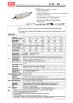
2.Front and back panel
Start
AC INLET ON/OFF SWITCH
Charge Voltage
ON
Fan
Ventilation
Hole
7.5 Temperature Compensation
Temperature sensor comes along with the charger can be connected to the unit to
allow temperature compensation of the charging voltage. If the temperature sensor
is not used, the charger still works normally.
V boost
100%
OFF
Power
8 Stage
AC INPUT
stage 1
Figure 2.1 Front Panel
Battery
Positive
LED
Indicator
8 Stage
1
3
5
7
9
State
V boost
Constant
Current
2 Stage
1 2
3 4
5 6
7 8
9 10
2
4
6
8
10
PB-600-48
57.6V
40A
21A
10.5A
+
-
WARNING : Please check
battery polarity
before connection
6.2 "8" stage charging (Selection switch to "8" stage)
Advantage of pulse stage: Use pulse current to revive aged battery.
Advantage of recond stage: Allow full charge of battery.
Advantage of Float and Maintain stage: After LED turns green, maintenance charge
is provided so the battery is always in a full state. User will have access to a full
battery whenever it is disconnected from the charger.
Figure 2.2 Back Panel
Assembly Guidelines:
1.The charger should be turned OFF prior to battery connection. Suitable wire gauge
should be chosen based on rated charging current of the PB-1000 unit. Double check
battery polarity before making the battery connection. Positive terminal of the charger
must be connected to "+" of the battery and negative terminal to "-" of the battery. Also, make
sure the positive and negative terminals of the charger are not accidentally shorted together.
2.After connecting the output cables, flick the ON/OFF (0/-) switch to the ON (-) position.
The indicator light on the switch will turn ON.
Notes on Operation:
1.Designed for charging lead acid battery.
2.Must be installed in a dry and well ventilated area. It should not be exposed to rain or snow.
3.The cables between charger and battery should be kept as short as possible to prevent
excessive line drop. Too much line drop will lead to longer charging period.
4.Please make sure charging voltage and current meets battery specification.
5.Refrain from connecting new and old batteries in series.
6.PB-1000 should be in the OFF mode before making battery connection or disconnection.
7.Three years warranty is provided under normal operating conditions. Failure resulting
from improper operation will result in cancellation of warranty.
USER'S MANUAL
PB-600-24
28.8V
Figure 6.1 2 Stage Charging Curve
Battery
PB-600
Start
Battery
Soft
Start
Battery
Pulse
Battery
Constant
Current
Battery
Constant
Voltage
Constant
Current
Constant
Voltage
..
PB-600-24
PB-600-48
BOOST CHARGE VOLTAGE
14.4V
28.8V
57.6V
FLOAT CHARGE VOLTAGE
13.8V
27.6V
RECOMMENDED BATTERY
OUTPUT CAPACITY(AMP HOURS)(Note 3)
BATTERY TYPE
OUTPUT CURRENT
VOLTAGE RANGE
FREQUENCY RANGE
PROTECTION
135 ~ 400Ah
(Note 4)
(Note 4)
70 ~ 210Ah
35 ~ 105Ah
21A
10.5A
100 ~ 240VAC
141 ~ 340VDC
50 ~ 60Hz
86%
87%
Soft
Start
POWER FACTOR (Typ.)
0.95/230VAC
0.98/115VAC at full load
6.8A/115VAC
3.4A/230VAC
INRUSH CURRENT (Typ.)
25A/115VAC
50A/230VAC
LEAKAGE CURRENT
<3.5mA / 240VAC
stage 1
stage 2
Color of
LED
stage 3
stage 4
Orange
OVER TEMPERATURE
Protection type : Shut down o/p voltage, recovers automatically after temperature goes down
REMOTE CONTROL
Open: Normal work
Short: Stop Charging
2 / 8 stage selectable
CHARGER OK
Relay contacts (RY15)
OUTPUT OK
Relay contacts (RY13)
TEMPERATURE SENSE (OPTIONAL) By NTC
WORKING TEMP.
WORKING HUMIDITY
ENVIRONMENT STORAGE TEMP., HUMIDITY
TEMP. COEFFICIENT
(Refer to output load derating curve)
20 ~ 90% RH non-condensing
-40 ~ +85
0.05%/
UL1012, TUV EN60335-1, EN60335-2-29 (except for 48V) approved
I/P-O/P:3KVAC
I/P-FG:1.5KVAC
O/P-FG:0.5KVAC
I/P-O/P, I/P-FG, O/P-FG:100M Ohms / 500VDC / 25
/ 70% RH
Compliance to EN55022 (CISPR22)
Compliance to EN61000-3-2,-3
EMS IMMUNITY
Compliance to EN61000-4-2,3,4,5,6,8,11; ENV50204, EN55024; light industry level, criteria A
135.6Khrs min.
MIL-HDBK-217F (25
)
230*158*67mm(L*W*H)
50
60
Battery capacity
Number
100AH
80AH
1~4
1~3
PB-600-48
46AH
1~2
11.Series and parallel connection of batteries
1.Batteries in series
CN100
NC
NC
Power
8 Stage
2 Stage
RY15 RY15
GND RTH
1 2
3 4
5 6
7 8
9 10
OFF
9
+
RC- RC+
When 2 batteries are connected in parallel,
voltage remains the same and the capacity
(AH)doubles. For example, 2 x 12V 100AH
batteries connected in parallel = 12V 200AH.
10
+
+
-
Battery
-
2.Batteries in parallel
Voltage can be doubled when 2 batteries
are connected in series. However, the
capacity (AH) will remain the same.
For example, 2 x 12V 100AH batteries
connected in series = 24V 100AH.
+
-
+
1. All parameters NOT specially mentioned are measured at 230VAC input, rated load and 25 of ambient temperature.
2. The power supply is considered a component which will be installed into a final equipment. The final equipment must be reconfirmed that it still meets EMC directives.
3. This is Mean Well's suggested range. Please consult your battery manufacturer for their suggestions about maximum charging
current limitation.
4. PB-600 unit can be operated within 90 ~ 264VAC of input voltage range and 47 ~63Hz of input frequency. Please check the
specification sheet for details.
-
Battery
Pin No. Function Description
Relay contact rating(max.) : 30V/1A resistive. ; "Short" when the battery
RY13
1,2
is full, "Open" when the battery is still charging
Relay contact rating(max.) : 30V/1A resistive. ; "Short" when the unit is
5,6
RY15
working properly, "Open" when the unit stop charging
Temperature sensor comes along with the charger can be connected to
7,8 GND / RTH the unit to allow temperature compensation of the charging voltage
If the temperature sensor is not used, the charger still works normally.
Turn the output on and off by electrical or dry contact between pin 10 (RC+)
9,10 RC- / RC+
and pin 9(RC-) Open : Normal work , Short : Stop charging
Battery status
-
Battery
Battery
Battery
70 (HORIZONTAL)
7.2 2 or 8 stage Charging mode Select
The charger features user selectable 2 or 8 stage charging. The charging profile is
selected by moving the slide switch on the back panel.
Switch
Charging mode
Turn right
2 stage charging
Turn left
8 stage charging
Power
8 Stage
Green
Red
Charging
Battery full
Fail
2 Damaged battery
Types of failure: 1 Battery disconnected
-
7.3 Charger OK Relay(RY15)
3 Reverse polarity
4 Incorrect battery voltage (e.g. PB-600-12 connected to 24V battery)
6.Explanation of Operation Logic (Charging stages):
8 stages charging differ from 2 stages with the addition of pulse, soft start, analysis, recond,
8 stages will allow charging to maximum capacity. User can select between 2 or 8 stages
depending on actual requirement.
6.1 "2" stage charging (Selection switch to "2" stage)
During initial charge (stage 1), charger will provide maximum current to the battery.
The built-in fan will also turn ON. As the battery starts to get full, charging current
will gradually decrease (stage 2). When charging current decrease to less than 10%
of max. LED indicator will turn Green indicating a full charge.
3
Normal work
CN100
1 RY13 RY13 2
Between pin5 and pin6
NC
ON (Short)
Battery reverse polarity
Battery with higher voltage is connected
Use battery with the
correct voltage
Input AC voltage is too low
Make sure input source
is between 90~264VAC
9
RC- RC+ 10
RY15
7.4 Output OK Relay(RY13)
1.Bank OK (RY13)
Between pin1 and pin2
Bank
LED indicator Battery exceed lifespan or damaged
does not turn
Green after a
long charging Output cables are too thin
period
Color of LED
Battery Full
ON (Short)
Green
Charging
OFF(Open)
Orange
RY13 RY13
NC
2
NC
RY15 RY15
GND RTH
9
RC- RC+ 10
RY13
5
Replace with suitable wire
gauge
WARNING : This is a class A product. In a domestic environment this product may cause
radio interference in which case the user may be required to take adequate
measures.
Against recharging non-rechargeable batteries.
CN100
1
Replace with a new battery
our distributors for repair service.
GND RTH
OFF(Open)
Ways to Eliminate
Switch to the ON position
Reconnect using correct
polarity
If you are not able to clear the failure condition, please contact Mean Well or any of
NC
RY15 RY15
Failure or the
protection function
is activating
Possible Reasons
2 Stage
+
Charger
Status
Unable to
charge the
battery
2 Stage
1 2
3 4
5 6
7 8
9 10
8 Stage
12.Failure correction notes
ON/OFF switch in the OFF position
Battery
Orange
float, and maintain stages. 2 stages provide simple and quick charging. On the other hand,
2.2Kg; 6pcs/14.2Kg/1.76CUFT
1
Model
PB-600-12
PB-600-24
6
SW
5 Activation of protection function (e.g. OTP, OVP, and Short)
HARMONIC CURRENT
PACKING
to the battery's technical specification or consult its manufacturer.
10.Suggested the number of cells
stage 8
Green
ON
SW Short
Color of LED
10 ~ 500Hz, 2G 10min./1cycle, 60min. each along X, Y, Z axes
MTBF
stage 7
Figure 6.2 8 Stage Charging Curve
5.LED Indication
)
SAFETY STANDARDS
OTHERS DIMENSION
stage 6
, 10 ~ 95% RH
(0 ~ 50
VIBRATION
WITHSTAND VOLTAGE
SAFETY & ISOLATION RESISTANCE
EMC
EMI CONDUCTION & RADIATION
(Note 2)
NOTE
-20 ~ +60
stage 5
20
40
35-105AH
battery. The only drawback is it may take longer to fully charge the battery.
SW Open
30
135-400AH
70-210AH
PB-600-48
2. If you're unsure about max allowable charging current of the battery, please refer
Between RC+(pin10)
Charger
and RC-(pin9)
20
Battery capacity
PB-600-12
PB-600-24
Charge
Current
1 RY13 RY13 2
10
2.1
3.3
5.3
10
16
25
Note:1. Using battery capacity larger than the suggested value will not lead to damage of
100
0
CROSS SECTION(mm )
14
12
10
7
6
4
Model
Maintain
7.1 Remote Control
4.Function Description of CN100
64.5 ~ 69.5V
Protection type : Shut down o/p voltage, re-power on to recover
FAST CHARGE
Float
7. Function description
40
Max. Current(A)
UL1015(600V 105 )
12
22
35
46
60
80
2
AWG
AMBIENT TEMPERATURE ( )
LEAKAGE CURRENT FROM BATTERY (Typ.) 1mA
FUNCTION
Recond
8.Wiring for battery
Select suitable wire gauge based on rated charging current. Refer to the following
table for minimum wire gauge. We highly recommend using RED wire for + connection
and BLACK wire for - connection:
Battery
Maintain
The charger can be turned ON/OFF by using the "Remote Control" function.
-20
32 ~ 35V
16 ~ 18V
Analysis
Battery
Float
Charge
Voltage
89%
AC CURRENT (Typ.)
OVER VOLTAGE
3.Derating Curves
3.1 Charging current VS Temperature
60
Open & Sealed Lead Acid
Battery
Recond
-
Battery
4
80
40A
EFFICIENCY (Typ.)
INPUT
( except for 48V )
PB-600-12
LOAD (%)
MODEL
Battery
Analysis
+
NTC
9.Suggested battery capacity
Pulse
2
1.Main Specifications
Green
PB-600-12
14.4V
1 2
3 4
5 6
7 8
9 10
The temperature
sensor can either
be attached to the
battery or placed
in its surrounding
environment.
Battery Full
Orange
Color of LED
Power
2/8 stage
selection switch
Function
Connector
stage 2
Constant Current Constant Voltage
Common
Negative
2 Stage
10%
Charge Current
7